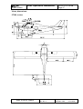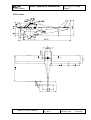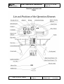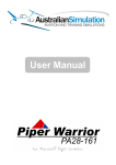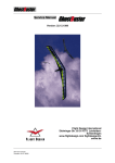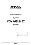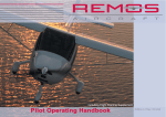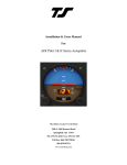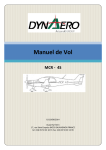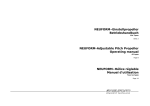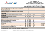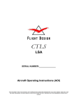
1
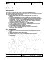
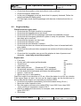
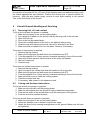
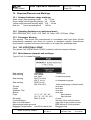
Flight Design CT-LSA Pilot Operating Handbook CT2K & CTSW LSA Sport Models SERIAL NUMBER: THIS DOCUMENT AND THE TECHNICAL DATA HEREON DISCLOSED ARE PROPRIETARY TO FLIGHT DESIGN AND SHALL NOT BE USED, RELEASED, OR DISCLOSED IN WHOLE OR IN PART WITHOUT EXPRESS WRITTEN PERMISSION FROM FLIGHT DESIGN FLIGHT DESIGN 1 Pilot Operation Handbook Aircraft Type: CT-LSA Page: 2 Table of Content Flight Design CT-LSA Pilot Operating Handbook............................................................ 1 1 Table of Content ................................................................................................... 2 2 General Information .............................................................................................. 4 3 Airplane and Systems Descriptions ...................................................................... 9 3.1 Engine ........................................................................................................... 9 3.2 Propeller ...................................................................................................... 11 3.3 Fuel and fuel capacity.................................................................................. 12 3.4 Oil ................................................................................................................ 12 3.5 Operating weights and loading (occupants, baggage, fuel, ballast) ............ 12 4 Operating Limitations.......................................................................................... 15 4.1 Stalling speeds at maximum takeoff weight (VS1 and VS0)........................ 15 4.2 Flap extended speed range (VS0 to VFE)................................................... 15 4.3 Maximum maneuvering speed (VA) ............................................................ 15 4.4 Never exceed speed (VNE) ......................................................................... 15 4.5 Crosswind and wind limitations.................................................................... 15 4.6 Service ceiling ............................................................................................. 15 4.7 Load factors................................................................................................. 15 4.8 Prohibited maneuvers.................................................................................. 16 5 Weight and Balance Information......................................................................... 21 5.1 Installed equipment list ................................................................................ 21 5.2 Center of gravity (CG) range and determination.......................................... 26 6 Performance: ...................................................................................................... 27 6.1 Takeoff and landing distances ..................................................................... 27 6.2 Rate of climb ............................................................................................... 27 6.3 Cruise speeds.............................................................................................. 27 6.4 RPM ............................................................................................................ 27 6.5 Fuel consumption ........................................................................................ 27 7 Emergency Procedures ...................................................................................... 28 8 Normal Procedures............................................................................................. 30 8.1 Preflight check ............................................................................................. 30 8.2 Engine starting............................................................................................. 31 8.3 Taxiing......................................................................................................... 32 8.4 Normal takeoff ............................................................................................. 32 8.5 Best angle of climb speed (VX) ................................................................... 33 8.6 Cruise .......................................................................................................... 33 8.7 Approach ..................................................................................................... 33 8.8 Normal landing ............................................................................................ 33 8.9 Short field takeoff and landing procedures .................................................. 34 8.10 Balked landing procedures .......................................................................... 34 8.11 Information on stalls, spins, and any other useful pilot information.............. 34 9 Aircraft Ground Handling and Servicing.............................................................. 35 9.1 Servicing fuel, oil, and coolant ..................................................................... 35 9.2 Towing and tie-down instructions ................................................................ 35 10 Required Placards and Markings .................................................................... 36 10.1 Airspeed indicator range markings .............................................................. 36 10.2 Operating limitations on instrument panel ................................................... 36 10.3 Passenger Warning ..................................................................................... 36 AU 010 01000 Rev. No.:2 Original Issue Date: 28.02.2005 Revision Date: 05.10.2005 FLIGHT DESIGN Pilot Operation Handbook Aircraft Type: CT-LSA Page: 3 10.4 “NO INTENTIONAL SPINS” ........................................................................ 36 10.5 Miscellaneous placards and markings......................................................... 36 11 Supplementary Information: ............................................................................ 37 11.1 Familiarization flight procedures .................................................................. 37 12 Revisions ........................................................................................................ 37 AU 010 01000 Rev. No.:2 Original Issue Date: 28.02.2005 Revision Date: 05.10.2005 FLIGHT DESIGN Pilot Operation Handbook Aircraft Type: CT-LSA Page: 4 In accordance with the specification F 2245 DESIGN AND PERFORMANCE OF A LIGHT SPORT AIRCRAFT each of CT-LSA airplanes includes a Pilot Operating Handbook (POH). The content and format herewith is defined by F 2245. Additional to F 2245 items are considered where necessary. All fight speeds are given in terms of calibrated airspeeds (CAS). All specifications and limitations are determined from the specification F 2245. 2 General Information Read this before your first flight! Every pilot has to understand the limitations and specifications of this light sport aircraft. The Pilot Operating Handbook must be read thoroughly. Please pay attention to the pre-flight and daily checks. Maintenance instructions for the aircraft are given in a separate Maintenance Manual. For maintenance of the Rotax ®engine, BRS emergency parachute system, if equipped, and other installed equipment refer to the original manufacturers’ manuals. Flight Design CT-LSA is being delivered in two configurations CTSW and CT2K (hereafter referred to as the CT-LSA). Both configurations are equipped with noncertified engines that meet Practice F 2339. Unless otherwise specified the data are common for both configurations. Note, where different CT2K data are given in square brackets. Flying CT-LSA must always be done with the possibility of a safe landing due to loss of the engine power. Flight Design CT-LSA is a VFR aircraft only. Because of the high cruising speed and range of the CT-LSA, flight into vastly different weather patterns and meteorological conditions can occur. The entry into bad weather with IFR conditions by VFR pilots and aircraft is extremely dangerous. As the owner or operator of an aircraft you are responsible for the safety of your passenger and yourself. Do not attempt to operate CT-LSA in any manner that would endanger the aircraft, the occupants or persons on the ground. Manufacturer: Flight Design GmbH Sielminger Str. 65 D – 70771 L.-Echterdingen Description of the aircraft: Flight Design CT-LSA is being delivered in two configurations CT2K and CTSW as shown below. CT-LSA is a three-axis control, high-wing, two seats light sport aircraft of normal scheme with a cruciform tail. The primary structures are made of carbon fiber reinforced plastic. The aircraft is equipped with an all-moving stabilator with a trim tab and tricycle landing gear with a steerable nose-wheel. AU 010 01000 Rev. No.:2 Original Issue Date: 28.02.2005 Revision Date: 05.10.2005 FLIGHT DESIGN Pilot Operation Handbook Aircraft Type: CT-LSA Page: 5 Views, dimensions: CTSW, inches AU 010 01000 Rev. No.:2 Original Issue Date: 28.02.2005 Revision Date: 05.10.2005 FLIGHT DESIGN Pilot Operation Handbook Areas, ft2 Wing Stabilator Vertical fin 107.4 17.745 12.978 Aspect ratio: Wing Stabilator 7.29 3.4 AU 010 01000 Rev. No.:2 Aircraft Type: CT-LSA Page: 6 Original Issue Date: 28.02.2005 Revision Date: 05.10.2005 FLIGHT DESIGN Pilot Operation Handbook Aircraft Type: CT-LSA Page: 7 CT2K, inches AU 010 01000 Rev. No.:2 Original Issue Date: 28.02.2005 Revision Date: 05.10.2005 FLIGHT DESIGN Pilot Operation Handbook Areas, ft2 Wing Stabilator Vertical fin 116.25 17.745 12.978 Aspect ratio: Wing Stabilator 8 3.4 AU 010 01000 Rev. No.:2 Aircraft Type: CT-LSA Page: 8 Original Issue Date: 28.02.2005 Revision Date: 05.10.2005 FLIGHT DESIGN 3 Pilot Operation Handbook Aircraft Type: CT-LSA Page: 9 Airplane and Systems Descriptions 3.1 Engine NOTE: for actual and complete information read the Rotax operation manual supplied with the aircraft. Type: 912 ......... 4-cyl. horizontally opposed, normal aspirated engine Description of design 4-stroke, 4 cylinder horizontally opposed, spark ignition engine, one central camshaft - push-rods - OHV Liquid cooled cylinder heads Ram air cooled cylinders Dry sump forced lubrication Dual breakerless capacitor discharge ignition 2 constant depression carburetors Mechanical fuel pump Prop drive via reduction gear with integrated shock absorber and overload clutch Electric starter (12V 0.6 kW) Integrated AC generator with external rectifier-regulator (12V 20A DC) Propeller gearbox reduction ratio crankshaft : propeller shaft 912 UL / A / F 2,27 : 1 2,43 : 1 (optional) 912 ULS / S 2,43 : 1 For the engine type 912 two reduction ratios are available. Depending on engine type, certification and configuration the propeller gearbox is supplied with or without an overload clutch. AU 010 01000 Rev. No.:2 Original Issue Date: 28.02.2005 Revision Date: 05.10.2005 FLIGHT DESIGN Pilot Operation Handbook Aircraft Type: CT-LSA Page: 10 Operating speeds and limits (912 UL / A / F) 1. Speed: Take-off speed ........................... 5800 1/min (5 min.) Max. continuous speed .............. 5500 1/min Idle speed ................................... ca. 1400 1/min 2. Performance (ISA): (International Standard Atmosphere) Take-off performance ................. 59,6 kW at 5800 1/min Max. continuous performance ... 58 kW at 5500 1/min 3. Acceleration: Limit of engine operation at zero gravity and in negative "g" conditions max. ............................................ 5 seconds at max. -0,5 g 4. Oil pressure: max. ............................................ 7 bar n ATTENTION: For a short period admissible at cold start. min. ............................................. 0,8 bar (12 psi) (below 3500 rpm) normal ......................................... 2,0 ÷ 5,0 bar (29 ÷ 73 psi) (above 3500 rpm) 5. Oil temperature: max. ............................................ 140° C.................. (285° F) min. ............................................. 50° C.................... (120° F) normal operating temperature ... ca. 90 ÷ 110° C ... (190÷230° F) 6. Cylinder head temperature: max. ............................................ 150OC .................. (300° F) reading at observation point of the hotter cylinder head, either no. 2 or no.3. 7. Engine start, operating temperature: max. ............................................ 50O C................... (120° F) min. ............................................. - 25O C .................. (- 13° F) 8. Fuel pressure: max. ............................................ 0,4 bar ................ (5,8 psi) min. ............................................. 0,15 bar ............... (2,2 psi) NOTE: Exceeding the max. admissible fuel pressure will override the float valve of the carburetor. The delivery pressure of an additional backing pump (e.g. electric standby pump) must not exceed 0,3 bar (4.4 psi) in order not to override the float valve. AU 010 01000 Rev. No.:2 Original Issue Date: 28.02.2005 Revision Date: 05.10.2005 FLIGHT DESIGN Pilot Operation Handbook Aircraft Type: CT-LSA Page: 11 Operating speeds and limits (912 ULS / S) 1. Speed: Take-off speed ........................... 5800 1/min (5 min.) Max. continuous speed .............. 5500 1/min Idle speed ................................... ca. 1400 1/min 2. Performance (ISA): (International Standard Atmosphere) Take-off performance ................. 73,5 kW at 5800 1/min Max. continuous performance ... 69 kW at 5500 1/min 3. Acceleration: Limit of engine operation at zero gravity and in negative "g" conditions max. ............................................ 5 seconds at max. -0,5 g 4. Oil pressure: max. ............................................ 7 bar • ATTENTION: For a short period admissible at cold start. min. ............................................. 0,8 bar (12 psi) (below 3500 rpm) normal ......................................... 2,0 ÷ 5,0 bar (29 ÷ 73 psi) (above 3500 rpm) 5. Oil temperature: max. ............................................ 130° C.................. (266° F) min. ............................................. 50° C.................... (120° F) normal operating temperature ... ca. 90 ÷ 110° C ... (190÷230° F) 6. Cylinder head temperature: max. ............................................ 135OC .................. (284° F) reading at observation point of the hotter cylinder head, either no. 2 or no.3. 7. Engine start, operating temperature: max. ............................................ 50° C................... (120° F) min. ............................................. - 25° C .................. (- 13° F) 8. Fuel pressure: max. ............................................ 0,4 bar ................ (5,8 psi) min. ............................................. 0,15 bar ............... (2,2 psi) NOTE: Exceeding the max. admissible fuel pressure will override the float valve of the carburetor. The delivery pressure of an additional backing pump (e.g. electric standby pump) must not exceed 0,3 bar (4.4 psi) in order not to override the float valve. More engine data is available in the Rotax operation manual supplied with the aircraft. 3.2 Propeller 1. Neuform TXR2-65-47-101.6 2-blade composite propeller, ground adjustable (standard). 2. Warp Drive 3-blade Tapered tip, Ground adjustable propeller with HPL-R hub (optional). 3. Neuform, carbon fiber, three-blade CR3-65-47-101.6 (optional) AU 010 01000 Rev. No.:2 Original Issue Date: 28.02.2005 Revision Date: 05.10.2005 FLIGHT DESIGN 3.3 Pilot Operation Handbook Aircraft Type: CT-LSA Page: 12 Fuel and fuel capacity Fuel specification: Premium Automotive Unleaded per ASTM D 4814, minimum AKI 89 for Rotax 912UL and minimum AKI 91 for Rotax 912ULS. For complete fuel specifications see the original Rotax Operator’s Manual. Fuel capacity: 2 wing fuel tanks 17.16gal (65l) each, 34.32gal (130l) total. 3.4 Oil For complete oil specifications see the original Rotax Operator’s Manual. Oil: Motorcycle oil of a registered brand with gear additives. If using aircraft engine oil; than only blonded one. n ATTENTION: At the selection of suitable lubricants refer to the additional information in the Service Information 18 UL 97. Oil specification — Use only oil with API classification "SF" or "SG"! — Due to the high stresses in the reduction gears, oils with gear additives such as high performance motor cycle oils are required. — Because of the incorporated friction clutch, oils with friction modifier additives are unsuitable as this could result in a slipping clutch during normal operation. — Heavy dury 4-stroke motor cycle oils meet all the requirements. These oils are normally no mineral oils but semi- or full synthetic oils. — Oils primarity for Diesel engines are due to insufficient high temperature properties and additives which favour clutch slipping, generally unsuitable. n ATTENTION: If the engine is mainly run on AVGAS more frequent oil changes will be required. See Service Information 18 UL 97. Oil capacity:................... 3 l (min. 2 l) (6.4 liq pt, min. 4.2 liq pt) Oil consumption: .......... max 0,1 l/h (0.2 liq pt/h) Oil viscosity: see Chapter 10 of the Rotax Operator’s Manual Use of multi-grade oils is recommended. 3.5 Operating weights and loading (occupants, baggage, fuel, ballast) Minimum load per seat: Maximum weight per seat: Empty weight (standard): Maximum permissible take off weight: Maximum baggage weight, for each side: 120 lb 260 lb 659.3 lb [665.9lb] 1320 lb 55 lb (54 kg) (118 kg) (299 kg) [(302kg)] (600 kg) (25 kg) Weighing Put the airplane on three scales or one scale with leveling blocks on a plane surface. Make certain the plane is leveled using a bubble level put onto the console (also called tunnel) between the seats. Mark the wheel axle positions on the ground using a plumb. AU 010 01000 Rev. No.:2 Original Issue Date: 28.02.2005 Revision Date: 05.10.2005 FLIGHT DESIGN Aircraft Type: CT-LSA Pilot Operation Handbook Page: 13 Typical loading configurations for CTSW. Full fuel tank, two passengers (most forward CG for maximum takeoff weight): mi Lb 658.3 0 455 0 205 1320 Xi kg 299 0 208 0 93 600 ft 1.02 4.17 1.71 3.58 0.98 M 0.31 1.27 0.52 1.09 0.3 xi*mi lb*ft kg*m 669.7 93 0 0 778.1 108 0 0 201.8 28 1649.6 229 Empty aeroplane Parachute system Passengers Baggage Fuel Total weight CG location 1.25 0.380 CG location, % of MAC 32.5% Full tank accommodates 34.32 US gal (130 litres) of fuel that multiplied by the fuel density of 6 lb/gal (0.72 kg/litre) weighs 205 lb (93.34 kg). Minimum fuel, two passenger and baggage (most rearward CG): mi Empty aeroplane Parachute system Passengers Baggage Fuel Total weight CG location CG location, % of MAC Lb 658.3 28.6 505.3 110 17.5 1320 Xi kg 299 13 230 50 8 600 ft 1.02 4.17 1.71 3.58 0.98 m 0.31 1.27 0.52 1.09 0.3 xi*mi lb*ft kg*m 669.7 93 119.2 17 864 120 393.8 55 17.2 2 2063.9 285 1.56 0.475 40.6% Full fuel tank and light passenger (most forward CG): mi Empty aeroplane Parachute system Passengers Baggage Fuel Total weight CG location CG location, % of MAC AU 010 01000 Lb 658.3 0 120 0 205 983 Xi kg 299 0 54 0 93 446 ft 1.02 4.17 1.71 3.58 0.98 m 0.31 1.27 0.52 1.09 0.3 xi*mi Lb*ft kg*m 669.7 93 0 0 205.2 28 0 0 201.8 28 1076.7 149 1.09 0.333 28.4% Rev. No.:2 Original Issue Date: 28.02.2005 Revision Date: 05.10.2005 FLIGHT DESIGN Aircraft Type: CT-LSA Pilot Operation Handbook Page: 14 Typical loading configurations for CT2K Full fuel tank, two passengers (most forward CG for maximum takeoff weight): mi Empty aeroplane Rescue system Passengers Baggage Fuel Total weight CG location CG location in MAC percent lb 666 0 452 0 205 1320 Xi kg 302 0 205 0 93 600 ft 1.03 4.17 1.71 3.58 0.98 m 0.314 1.27 0.52 1.09 0.3 xi*mi lb*ft kg*m 685.8 95 0.0 0 771.0 107 0.0 0 201.8 28 1658.6 229.3 1.25 0.382 32.6% Full tank accommodates 34.32 US gal (130 litres) of fuel that multiplied by the fuel density of 6 lb/gal (0.72 kg/litre) weighs 205 lb (93.34 kg). Minimum fuel, two passenger and baggage (most rearward CG): mi Empty aeroplane Rescue system Passengers Baggage Fuel Total weight CG location CG location in MAC percent lb 666 28.5 501 109 17.5 1320 Xi kg 302 13 227 50 8 600 ft 1.03 4.17 1.71 3.58 0.98 m 0.314 1.27 0.52 1.09 0.3 xi*mi lb*ft kg*m 685.8 95 119.4 17 853.7 118 394.2 55 17.4 2 2070.5 286.3 1.565 0.477 40.8% Full fuel tank and light passenger (most forward CG): mi Empty aeroplane Rescue system Passengers Baggage Fuel Total weight CG location CG location in MAC percent AU 010 01000 lb 666 0 119 0 205 990 Xi kg 302 0 54 0 93 449 ft 1.03 4.17 1.71 3.58 0.98 m 0.314 1.27 0.52 1.09 0.3 xi*mi lb*ft kg*m 685.8 95 0.0 0 203.1 28 0.0 0 201.8 28 1090.7 151 1.102 0.335 27.6% Rev. No.:2 Original Issue Date: 28.02.2005 Revision Date: 05.10.2005 FLIGHT DESIGN 4 4.1 Page: 15 Operating Limitations Stalling speeds at maximum takeoff weight (VS1 and VS0) flaps - 6º [- 12º] flaps - 0º flaps 40º 4.2 Aircraft Type: CT-LSA Pilot Operation Handbook VS1 VS1 VSO 44 kts [43 kts] 42 kts [41 kts] 39 kts [37 kts] Flap extended speed range (VS0 to VFE) Maximum speed with flaps extended: - to 0° is 100kts; - to 15° is 80kts; - to 30° is 62kts; - to 40° is 62kts. 4.3 Maximum maneuvering speed (VA) VA=98.6 kts [100.5 kts] (113 mph) [115.4 mph]) Up to the speed VA all control surfaces can be fully deflected. Maximum speed in turbulent air (VRA) VRA =120 kts (138 mph) At the speed VRA the aircraft supports a vertical gust of 50 ft/s (15.24 m/sec) without being structurally overloaded. 4.4 Never exceed speed (VNE) VNE =145 kts. (166.6 mph) Note, that the maximum operating speed for BRS1350 emergency parachute system is 178 kts. From VA to VNE only use of 1/3 of the maximum deflections of the control surfaces is allowed. 4.5 Crosswind and wind limitations Maximum direct cross wind components for take off and landing with flaps from -6º to 15 º 16-13 kts; with flaps more than 15º to 40 º 13-11 kts. Cross wind take-offs and landings demand a lot of training and skill, the higher the crosswind component, the greater your skill must be. In gusty wind or wind speed more than 21 kts (24 mph) flight operations should be stopped. 4.6 Service ceiling Maximum service ceiling is about 14,000ft (about 4,250m). 4.7 Load factors From VSO up to VNE AU 010 01000 + 4 g/ -2 g Rev. No.:2 Original Issue Date: 28.02.2005 Revision Date: 05.10.2005 FLIGHT DESIGN 4.8 Pilot Operation Handbook Aircraft Type: CT-LSA Page: 16 Prohibited maneuvers The CT-LSA is not certified for aerobatics. Steep turns beyond 60° should not be performed. Other limitations: Flights are only to be made under VFR conditions. Night flights require special optional equipment. Flights in icing conditions not allowed. Structures and Systems Description Fuselage – Wing: The fuselage of the CT-LSA is made of multiple layers of carbon fiber and aramid (Kevlar) laminated over a dense foam core creating a sandwich structure. The cabin can resist loads from all sides. This provides superior pilot and passenger crash protection and low structural weight. Wings: The cantilevered wing of the CT-LSA plugs into 4 hard points at the top of the cabin for attachment to the fuselage. The overlapping spars resist lift loads. The main spar caps are solid carbon fiber wrapped with S glass fibers over a dense Rohacell core. The wing “skin” is a carbon fiber sandwich. The ribs are molded carbon fiber and bonded into place. Wingtips: The wingtips of the CT are highly developed drooped type. They reduce stall speed, improve stability and low speed control of the CT. Fuel system: Fuel is supplied from the two wing tanks by gravity feed with a total capacity of 34 Gallon. The ignition key cannot be inserted unless the fuel valve is in the on position. Electric system: The Rotax 912 series engines have a lighting coil type alternator with a rectifierregulator converting and regulating the accessory voltage to a nominal 13.5 V – 14.2V 250W (roughly 18A). The battery for the electric starting system is 12V sealed, AGM type. The dual ignition system is a CDI (capacitive discharge). Landing gear: The landing gear of the CT is of tricycle type. The nose wheel is steerable through a direct link to the rudder pedals. The main gear legs are heavy duty machined aluminum rods. Brakes: Hydraulic disk type, actuated through a handbrake lever. Parking brake is set by simultaneous use of the brake knob and valve. Control surfaces: The movable surfaces of the CT-LSA are of aramid-foam-aramid, carbon-foam-aramid, carbon-foam-carbon sandwiches with carbon fiber spars and attachment points. AU 010 01000 Rev. No.:2 Original Issue Date: 28.02.2005 Revision Date: 05.10.2005 FLIGHT DESIGN Aircraft Type: CT-LSA Pilot Operation Handbook Page: 17 Rudder: Conventional type with balance. Activated by the foot pedals with cables. Stabilator: Al-moving type with trim tab and balance, actuated with a ball bearing push pull connected to the twin cockpit located control sticks. Ailerons: Frise type. Controlled with push pull tubes and rod bearings. The ailerons move simultaneously with the flaps together from 0º to -6º [-12º]. The ailerons also droop automatically with the flaps for reduced stalling speed. Flaps: Slotted type. Pre-selector switch activated from -6º to +40º [-12º to +40º]. The flap position is indicated on the screen of the flap position indicator on the control panel. The flaps run to the next setting selected and are protected by limit switches at the end limits (-6º to +40º) [-12º to +40º]. -6º [-12º], 0º, +15º, +30º, +40º settings are available. Do not exceed the maximum flap extended speed VFE as stated in item 4.2! Stabilator Trim System: Activated with the wheel near the throttle and choke controls. Forward – nose down, back – nose up. Aileron Trim System, if equipped: Activated with the wheel on the top of the tunnel between the pilots. Right – right bank, left – left bank. Rudder Trim System, if equipped: Activated with the wheel on the bulkhead right above the tunnel. Right – right turn, left – left turn. Optional BRS Parachute system (Also see separate BRS instruction manual): Rocket deployed emergency parachute system. Actuated through the red, “T” handle above the console (or “tunnel”) between the seats. The parachute is secured on the ground with a safety pin and tag. Remove pin for flight operations. In case of emergency pull the handle hard out to the stop. AU 010 01000 Rev. No.:2 Original Issue Date: 28.02.2005 Revision Date: 05.10.2005 FLIGHT DESIGN Pilot Operation Handbook Aircraft Type: CT-LSA Page: 18 Standard equipment with Flydat AU 010 01000 Rev. No.:2 Original Issue Date: 28.02.2005 Revision Date: 05.10.2005 FLIGHT DESIGN Pilot Operation Handbook Aircraft Type: CT-LSA Page: 19 Control Box Flap position indicator AU 010 01000 Ignition switch and starter Rev. No.:2 Original Issue Date: 28.02.2005 Revision Date: 05.10.2005 FLIGHT DESIGN Aircraft Type: CT-LSA Pilot Operation Handbook Page: 20 Flydat – Rotax for water-cooled 4-stroke engine 912 ULS Display panel Description Unit Resolution 1 ………………………RPM…………………. …………1/min…………………1 2……………………… Operation hours…………..…….hour………………….0,1 3……………………….Exhaust gas temperature AS…...ºF………………..1 or 10 4……………………….Exhaust gas temperature MS…. ºF………………..1 or 10 5……………………….Cylinder head temperature ….. ..ºF……………………1 6……………………….. x) 7……………………….Oil temperature………………… ºF……………………1 8……………………….Oil pressure ……………………...PSI ………………..0,1 x) Indicator of cylinder series, for which the exhaust gas temperature is indicated. NOTICE: Arrowhead pointer ← symbolizes left cylinder series. Arrowhead pointer → symbolizes right cylinder series. Switching of exhaust gas temperature is carried out in 6-8 sec. intervals. Rotax 912UL, 912 ULS Indicator Unit RPM / rotation speed (1/min) EGT/Exhaust gas temperature (ºF) CHT/cylinder head temperature, UL (ºF) CHT/cylinder head temperature, ULS(ºF) Oil temperature, UL (ºF) Oil temperature, ULS (ºF) Oil pressure, max Oil pressure, min Oil pressure, normal AU 010 01000 Warning limits 5800 1616 300 284 285 266 (PSI) (PSI) (PSI) Rev. No.:2 102 12 29-73 Original Issue Date: 28.02.2005 Revision Date: 05.10.2005 Pilot Operation Handbook FLIGHT DESIGN 5 5.1 Aircraft Type: CT-LSA Page: 21 At exceeding one or more warning limits they are indicated on the display blinking and the alarm lamp blinks. At exceeding one or more not-permissible values (alarm limit values) they are also indicated on the display blinking and the alarm lamp blinks with long-term blinking. Rotax Operation Manual should always be followed! Weight and Balance Information Installed equipment list A-10000 Airplane CT2K LSA SPORT version ready to fly Equipment Drooped tips(reduce induced drag and increase directional stability) 3 tones paint inside the cabin 2-components outside paint- white 2 layers Swiss or German aeronautical windows with green tone Adjustable seats (length and height) 4-points safety belts for each seat 2 luggage compartments accessible from outside & inside Fabric cover for the luggage compartments Luggage security hooks in the luggage compartment 2 lockers on the cabin floor Huge cockpit with three single instrument panels Inspection door on cowling for quick oil and water check Extra wide cabin doors with gas struts Dual controls, 3 Axis Pre-installed bridges for BRS Parachute system Plexiglas inspection window for bellcrank Manual stabilizer trim by lever Electrical flap for -12°to +40° with pre-selector switch Switch board panel with circuit breakers Combination key switch Central fuel valve 2 wing tanks for 17 gallons = 34 gallons Steerable spring damped front wheel Hydraulic disk brakes Flight Instruments Airspeed indicator in knots Three point altimeter Magnetic compass Slip & bank indicator AU 010 01000 Rev. No.:2 Original Issue Date: 28.02.2005 Revision Date: 05.10.2005 FLIGHT DESIGN Pilot Operation Handbook Aircraft Type: CT-LSA Page: 22 Engine: Rotax 912 UL2 (80 HP) ready to fly installed Airbox & Carburetor heating Tachometer Large Battery Rotax engine guarantee Propeller Neuform ground adjustable Ground adjustable Neuform propeller, with Spinner and Spinner plate, already mounted Flight and service manual A-10050 Airplane CTSW LSA SPORT version ready to fly Equipment Short wings with Drooped tips(reduce induced drag and increase directional stability) 3 tone paint inside the cabin 2-components outside paint- white 2 layers Swiss or German aeronautical windows with green tone Adjustable seats (length and height) 4-point safety belts for each seat 2 luggage compartments accessible from outside & inside Fabric cover for the luggage compartments Luggage security hooks in the luggage compartment 2 lockers on the cabin floor Huge cockpit with three single instrument panels Inspection door on cowling for quick oil and water check Extra wide cabin doors with gas struts Dual controls, 3 Axis Pre-installed bridges for BRS Parachute system Plexiglas inspection window for bellcrank Manual stabilizer trim by lever Electrical flap for -6° to +40° with pre-selector switch Switch board panel with circuit breakers Combination key switch Central fuel valve 2 wing tanks for 17 Gallons = 34 Gallons Steerable spring damped front wheel Hydraulic disk brakes Flight Instruments Airspeed indicator 3 Point altimeter Magnetic compass Slip & bank indicator AU 010 01000 Rev. No.:2 Original Issue Date: 28.02.2005 Revision Date: 05.10.2005 FLIGHT DESIGN Pilot Operation Handbook Aircraft Type: CT-LSA Page: 23 Engine: Rotax 912 UL2 (80 HP) ready to fly installed Airbox & Carburetor heating RPM meter Oil pressure Oil temperature Cylinder head water temperature measurer Large Battery Rotax engine guarantee Propeller Neuform ground adjustable Ground adjustable Neuform propeller, with Spinner and Spinner plate, already mounted Flight and service manual B-00010X Addition on price 912 ULS 100PS (n. Sec. S) Rotax 912 ULS with big Starter instead 912 UL2 C-00203X Add-On Warp Drive 3 Blade Prop. w. L/E protection C-00205 Add-On Neuform 3 Blade Prop. Black & White Z-11020X Rotax slipper clutch Protection against shock loading of engine by ground contact of propeller Z-15101X Add-on price Rotax FlyDat °F & PSI Digital engine information system instead of analog instruments: black box, 4* EGT, 1*CHT, oil temp., RPM, hours, oil pressure. Warning when maximum values are exceeded! D-12300X BRS 1350 Rescue system Mounted, belts inside structure D-12200X BRS front harness Special BRS Kevlar belts instead of standard belts Z-10010 3-Axes trim system manual Manual stabilizer-/Rudder/Aileron Wheel trim Z-10020X TruTrack Digitrak 1-Axes Autopilot not certified Aileron Z-10025X Pictoral Pilot 1-Axes Autopilot not certified Aileron & turn & bank indicator Z-10030X TruTrack DigiFlight II 2-Axes Autopilot not certified Aileron & Stabilizer Z-10040X TruTrack DigiFlight IIVS 2-Axes Autopilot not certified Aileron & Stabilizer with vertical steering Z-15451.2X Vertical speed indicator ft/min Z-15452X Add-on price three pointer Altimeter Z-10200X KX 125 NAV/COM (* VOR, Intercom 2-place, High Noise Environment Stereo, 2 PTT push bottoms, 2 Antenna's, 2 Peltor Head sets, ready mounted. TSO & FAA certified. AU 010 01000 Rev. No.:2 Original Issue Date: 28.02.2005 Revision Date: 05.10.2005 FLIGHT DESIGN Z-10300X Z-10400X Z-10650X Z-10651X Z-10700X Z-10100++ Z-10110X Z-10120X Z-10150X Z-10160X Z-10170X Z-10130X Z-10140X Z-10180X Z-10111X Z-10161 Z-10200x Z-10230 Z-10240 Z-10250 Z-13050++ Z-13050.2++ Z-13060++ Z-13060.1++ Pilot Operation Handbook Aircraft Type: CT-LSA Page: 24 KY 97 A Com (* Intercom 2-place, High Noise Environment Stereo, 2 PTT push bottoms, 2 Antenna's, 2 Peltor Head sets, ready mounted. TSO not certified! FAA certified. King KT 76 A Mode A/C Transponder mont. (* Incl. Antenna and altitude encoder ACK A 30 Skyforce IIIC enhanced Atlantic Intl (* Incl. antenna and data cable cockpit mounted Garmin 296 Preparation Cable, metal frame ELT (* Emergency transmitter (required in Austria), completely mounted – TSO & FAA certified Comfort package (not Section S) Heating system with stainless steel muffler Wheel- and landing gear fairings 12 V connector Additional MECAPLEX double fresh air windows in door windows Additional map holders in the cockpit Door locks Parking brake ACL- & Position lights (green, white, red) not certified for night flight Extra capacity heater for very low out side temperatures Photowindow Add-On price instead of ventilation window Tundra Wheels w. wheel fairings Stainless steel bolts & nuts, special surface treatment, metal parts for float attachment Amphibfloats (Czech Artworks 1300) Floats complete mounted Skis additionally to the normal landing gear Part 91 compliant Night Light Package Black leather seats (add-on-price) Seats and stick base covered with same leather Light Brown leather seats (add-on-price) Seats and stick base covered with same leather Three color design Three color decals SN 1 AU 010 01000 Rev. No.:2 Original Issue Date: 28.02.2005 Revision Date: 05.10.2005 FLIGHT DESIGN Z-13060.2++ Z-13060.3++ Z-13060.4++ Z-13061.1++ Z-13061.2++ Z-13061.3++ Z-13061.4++ Z-13068X Z-13069X Z-14000X Z-14100X Z-14200X Z-13090X Z-13090.1X Z-13090.2X Z-13090.2X Z-13090.3X Z-16000.2 Z-16000.3 Z-16000.4 Z-16100.2 Z-13070X Pilot Operation Handbook Aircraft Type: CT-LSA Page: 25 Three color decals SN 2 Three color decals SN 3 Three color decals SN 4 Three color decals SW 1 Three color decals SW 2 Three color decals SW 3 Three color decals SW 4 1 colour Special paint(only bright colours) Colors according RAL standard only Custom made decals Colors according chart Add-On Aero towing equipped Reinforcement of fuselage & fin, clutch, mirror, special cooler Add-On Reinf. of fusel. for towing (no fin & clutch) Add-On Re. Fusel. & fin for towing (no Clutch) Custom made instrument panels, Standard Custom made instrument panels, aluminum Custom made instrument panels, mahogany Custom made instrument panels, ash ice blue Custom made instrument panels, grey ASI in mph ASI in kts ASI in kts & mph Altimeter in hg N Numbers Ordering and mounting of registration number AU 010 01000 Rev. No.:2 Original Issue Date: 28.02.2005 Revision Date: 05.10.2005 FLIGHT DESIGN 5.2 Aircraft Type: CT-LSA Pilot Operation Handbook Page: 26 Center of gravity (CG) range and determination Range of center of gravity: 13.110 – 18.740 in. (333 – 476 mm) behind the leading edge of wing. Note, that while determining the center of gravity, the aircraft must be level. The center of gravity is normally located behind the leading edge of wing. Spanwise location of the datum is not important, as the wings are rectangular and un-tapered. A Weight and Balance Sheet is supplied with each plane. The example of it is shown below. Weight Weight & Balance and and Model CTSW Balance Serial-Nr 05-01-02 Sheet Motor-Nr. 4406791 Technical data according data sheet Datum: Leading Edge Leveling: Top of fuselage tunnel Item kg NWCP kg Empty weight Wing right 34,5 Wing left 34,3 Useful load Fuselage 219,3 219,3 MTOW Elevator 9,6 9,6 Rudder 2,5 2,5 Weight NWCP Wing struts (50%) incl.useful load useful load 259,8 remarks total weight 300,2 Reference from G1 from G2 gross (kg) tare (kg) net (kg) Weight G= BP a a b 300,2 kg 259,8 kg 560 kg 491,2 kg Arm (mm) 870 1450 Name ASI Altimeter Compass Variometer/VSI Tachometer Radio Oilpressure gauge Oiltemp gauge Watertemp gauge Battery Rescue system Fly.Dat Clock AI (Horizon) Transponder Turn and Bank GPS ELT Towhook Autopilot Model 6FMS443 ALT20MBF-3 Airpath SBS 8 BRS Tricycle Gear AC Producer C.g. position Winter -220 FALCON GAUGE -220 Airpath Instrument CO -220 ROTAX -210 VDO VDO VDO HAWKER -210 -210 -210 -580 1170 x S G=G1+G2 G G1 61,0 239,2 300,2 Equipment List G2 b CG empty according G2*b/G-a= empty CG limits from…280…to…320…at 285 300,2 kg AU 010 01000 Fedchun Weighed by Rev. No.:2 Kherson, Ukraine Location 27.01.2005 Date Original Issue Date: 28.02.2005 Revision Date: 05.10.2005 FLIGHT DESIGN 6 Pilot Operation Handbook Aircraft Type: CT-LSA Page: 27 Performance: The performance figures stated below are given at the sea level of the international standard atmosphere conditions. Operations at higher altitudes and temperatures will reduce takeoff and climb performance. 6.1 Takeoff and landing distances Take-off range over 50 Ft. (15 m) obstacle with MTOW=1320lb,.912 ULS engine, and Neuform TXR2-65 propeller on an asphalt runway is 762ft. Landing distance over 50ft (15m) obstacle is 967ft. Liftoff speed with 15º of flaps: 40kts (46mph) 6.2 Rate of climb For 912 ULS and Neuform TXR2-65: Best rate of climb 885 fpm (4.5 m/s) at VY 78 kts. (89 mph) at 5100 RPM at 0º flaps position 6.3 Cruise speeds For 912 ULS and Neuform TXR2-65 Maximum cruising speed at 75%: max. range ability with 1320 Lbs (600 Kg): 6.4 RPM Take-off performance: Max. continuous performance: Min RPM before take-off: Idle speed: Maximum RPM (Redline): Cruising flight RPM: 75 Percent cruise RPM: 6.5 112 kts. (129 mph) 783 nm. (900 Miles) ROTAX 912 UL 912 ULS 4500 4800 5500 4400 RPM 4700 RPM 1400-1500 RPM 5800 RPM (max. 5 min) 4200 – 5500 RPM 5200 RPM Fuel consumption Fuel consumption at take-off power: Fuel consumption at cruising power: Fuel consumption at 5500 RPM: 5.12 Gph (19 l/h) 3.44. – 5.82 Gph (13-22 l/h). 6.88 Gph (26 l/h). For more engine data, refer to the Rotax Operator’s Manual supplied with the airplane. AU 010 01000 Rev. No.:2 Original Issue Date: 28.02.2005 Revision Date: 05.10.2005 FLIGHT DESIGN 7 Pilot Operation Handbook Aircraft Type: CT-LSA Page: 28 Emergency Procedures Stalls: The loss in altitude during stalls is approximately 165ft, with a maximum pitch down of 25º. In the case of a stall-spin entered through crossed controls: Oppose a spin with opposite rudder input. Center the ailerons and elevator until the rotation stops, then level out the airplane gently. If the attempt to level out the airplane fail or leveling out is doubtful because of too low altitude the emergency parachute system (if equipped) should be actuated. Engine failure: At an altitude of less than 330 ft., no attempt to re-start the engine should be made. Below and altitude of 820 ft., no attempt to return to the runway should be made. Choose a landing spot without trees or obstacles and with sufficient length. Below an altitude of 165 ft. any turns are to be avoided because of increased loss of in altitude and/or control. Keep a minimum speed of 54 kts (62 mph) until final approach. In case of landing on a field with crops or in a forest: • Look for a flat spot in the plants, treetops or bushes. • For final approach, the flap position should be 40 degrees and airspeed should be 43 kts. (50 mph) on short final. • The final flair for landing should be carried out at a height of about 1.5 ft. over the chosen spot. • Ignition should be turned off. • The elevator control should be fully pulled back. Carburetor: In case of engine fire • shut down the engine • take out the key • close the fuel valve • full-open throttle • Slip away from the location of the smoke if possible • land as quickly as possible • perform an emergency landing • If the fire is extinguished and there is no emergency landing possibility without engine help, insert the key and try to start the engine again – if it starts, land as quickly as safely possible. • If the airplane is not under control during a fire or there is no emergency landing possibility, the optional parachute system should not be used at higher altitudes. The airplane should be flown down to 700 ft. (200 m), and then the system operated. • After landing, leave the airplane immediately. AU 010 01000 Rev. No.:2 Original Issue Date: 28.02.2005 Revision Date: 05.10.2005 FLIGHT DESIGN Pilot Operation Handbook Aircraft Type: CT-LSA Page: 29 Optional BRS Parachute system: The data and directions in the BRS 1350 LSA Parachute Manual concerning the emergency parachute system should be followed. The BRS parachute system has shown the ability to be used for low altitudes as well. In an emergency, the parachute system should be activated even if at a very low altitude. Before activating, if possible, stop the engine and tighten the pilot and passenger harnesses. The parachute system handle is located above the central console between the seats. To activate the system, the handle has to be pulled to the stop. Overturn on land: • • • Carefully unfasten the seat belts and lower yourself first, then your passenger. Be careful of any spilled fuel – there may be a fire hazard! Leave the airplane immediately. AU 010 01000 Rev. No.:2 Original Issue Date: 28.02.2005 Revision Date: 05.10.2005 FLIGHT DESIGN 8 Pilot Operation Handbook Aircraft Type: CT-LSA Page: 30 Normal Procedures Daily flight check: At the start of every new flying day the CT should be checked thoroughly. An accidental engine start is very dangerous, that is why you must always ensure that the ignition and main switch are turned off! • Make sure that the throttle and choke controls are free from friction and binding. • Check the coolant level on the Rotax overflow bottle and add more if needed. • Check the oil level and add more if needed. The oil level should be between the two markings – max/min – of the oil dipstick and should not be lower than the minimum mark in any case. Before a long-term engine operation the oil level should be in the middle of two marks at least. • Carefully examine the oil, cooling and fuel system for leaks. • In case of the any in-operative equipment, the engine should not be started before proper maintenance is performed. • Check that all visible bolts are fastened and secured. • In case of cracks or scratches on the paint finish their cause must be determined. Repair if necessary. 8.1 Preflight check • • • • • • • • • • • • • • • • Check the fuel in both tanks using the dipstick. Check that the tank vents are clear. Make sure both tank caps are closed tightly. Move the fuel valve lever to on. This exposes the starting key switch. Remove possible water from fuel system and control fuel flow by draining the fuel gascolator. Check fuel for contamination. If contaminated, drain until fuel is clear. Make certain the control stick and rudder pedals are free. Check flaps. Run the flaps to each of the settings within normal operating range of -6°[-12°] to 40° and watch for corresponding indicator readings. Specifically watch that for -6° and 40° settings the indicator must not blink. Otherwise refer to the CT-LSA Maintenance Manual. Check that the main spar bolts are secure. Check that the trim system is functioning. Check that all the hinge points are free. Check that all the wing control surfaces are secure and free. Check the stabilator attach bolts for security Check that the trim tab is bolted and the spring pin is secured. Check that the Pitot tube cover is removed. Check that the Pitot tube is clear. Check the conditions of the tires. Check the tire air pressure (28 PSI). Check that the wheel pants and fairings are secure. Check that the air intakes for the oil cooler, water radiator and cylinder air cooling are clear. AU 010 01000 Rev. No.:2 Original Issue Date: 28.02.2005 Revision Date: 05.10.2005 FLIGHT DESIGN • • • • 8.2 Pilot Operation Handbook Aircraft Type: CT-LSA Page: 31 Check that the propeller is free and without nicks or defects. Check the spinner attachment. In the case of baggage is carried, check that it is properly fastened. Follow the weight and balance loading plan! For solo flight, check that the passenger side harness is fastened and door is closed. Engine starting Checklist before engine start: • Check that the Pre-flight checklist is completed. • Check that the baggage doors are closed. • Check that the pilot and the passenger harnesses are fastened correctly. • Check that the emergency parachute system is ready for operation. Check that the safety pin is removed. • Check that the elevator trim tab is set. • Check that the altimeter is set. • Check that the wind direction is known. • Check that the doors are closed and secured (Door lever is forward and latch pins visible). • Check that the radio and other equipment are switched off before starting the airplane. • Check that the immediate area around the airplane is clear of persons and obstacles – especially around the propeller. Engine start: • Fuel valve open • Choke (with cold engine) pull backwards on • Throttle level idle position • Carburetor heat off • Main safety devices (Parachute, ELT if equipped) on • All electrical equipment , for example, radio equipment off • Pull the brake lever backwards and fasten the parking brake on • Ignition – both circuits on • Ignition key turn to start position on Crank the engine for a maximum of 10 sec. Allow the starter to cool for two minutes if the engine does not start. As soon as the engine starts, set the throttle level in such a way that the engine runs smoothly at minimum RPM. • Check the oil pressure immediately (it should increase during 10 sec.) • Move the choke forward to close • Run the engine until warm at a middle RPM, 2 min 2000 1/min, then 2500 1/min until the oil temperature rises to 124 F. • Switch on additional instruments, for example, radio, strobe light, position lights, GPS, ELT. • Set brakes. AU 010 01000 Rev. No.:2 Original Issue Date: 28.02.2005 Revision Date: 05.10.2005 FLIGHT DESIGN • • • • 8.3 • • • • • • • • • • • • • Pilot Operation Handbook Aircraft Type: CT-LSA Page: 32 Perform a “Mag” check on both of the ignition circuits at 4000 RPM; the maximum allowable drop in RPM is 300 and 120 RPM difference between the two circuits. If the airplane rolls and cannot be stopped with the brakes, the engine should be stopped immediately. The airplane tends to roll more easily on asphalt or with a tail wind, even with the engine at idle. The nose wheel is directly linked to the rudder pedals for taxiing, takeoff and all maneuvers on the ground. After practice, the airplane can be taxied in crosswinds up to 17kts (20 mph). Taxiing Before takeoff: Make certain the oil temperature is at least 124 F. Confirm again both doors are secured. Confirm the pilot and the passenger harnesses are properly fastened. Check that the controls are free and correct. Confirm the main switch and the ignition are “on” (both circuits). Choke is “closed”. Check that the alternator warning light is off. Do not take off with the red light on. Set the flaps to 0º-15º. Confirm the trim lever is set for takeoff. Check that the radio frequency and the squelch are set. Check that the runway and taxiways are clear. Check that the brakes are off. Make certain the clear takeoff distance is sufficient. 8.4 Normal takeoff • If the runway and approach to the runway are clear. Roll out to the take-off position. Confirm the nose wheel is centered. Controls are in proper position for takeoff. Apply the throttle smoothly to fully open (forward). Engine speed: 4400 – 4900 RPM Flaps: 15º (0º is fine on longer runways) If it is possible, take-off directly into the wind. The maximum direct crosswind component at take-off is 16 kts (18.5 mph) As soon as the airplane accelerates, gently pull back on control stick – keep the nose wheel slightly elevated until the airplane takes off. After take-off, release the back pressure on the stick slowly as airspeed builds to 59 kts. (68 mph). Climb to a minimum height of 600 ft. in straight ahead flight at 59 kts. (68 mph) before attempting to turn the aircraft. Do not reduce the flaps to below 0º with less than 59 kts (68 mph) airspeed. • Climb Decrease the flaps to -6º and increase the climb speed to 86kts (100 mph). • • • • • • • • • AU 010 01000 Rev. No.:2 Original Issue Date: 28.02.2005 Revision Date: 05.10.2005 FLIGHT DESIGN 8.5 Aircraft Type: CT-LSA Pilot Operation Handbook Page: 33 Best angle of climb speed (VX) Best angle of climb speed is 66 kts with flaps at 0˚. Best rate of climb speed (VY) For 912 ULS engine and Neuform TXR2-65 VY 78 kts. (89 mph) at 5100 RPM at 0º flaps position at rate of climb 885 fpm (4.5m/s) 8.6 Cruise During cruising flight, an RPM of 4200 – 5500 RPM should be used (redline is 5800 RPM). The maximum permissible speed of 145 kts (167 mph) should not be exceeded. During cruising flight, monitor your fuel consumption and total fuel on board for flight planning. Fuel consumption at cruising flight is about 4.7 gallons (18L) per hour. In case of possible carburetor icing, pull on the carburetor heat (immediately after icing clears, push it back in again). For normal cruising flight, bring the airplane to the desired cruising speed in level flight by observing the VSI or the altimeter. Adjust the throttle and trim to hold altitude. 8.7 Approach Land into the wind or the runway with the least crosswind if possible. The final approach to landing is to be carried out in level attitude. Engine power at: about 10-20 % slightly above idle to confirm that the engine still has power. Approach speed about 54 kts. (62 mph) with experience, a slightly slower approach speed can be used. Flaps from 15º to 40º In case of carburetor icing hazard pull the carburetor heating. 8.8 Normal landing At the distance of 3 ft. over the ground close the throttle and land the airplane gently. If engine cools too much in descent with the engine at idle and won’t increase RPM, pull the choke and then increase throttle. Close the choke again. When landing with crosswind, perform a crabbing approach or slip carefully. The flights over obstacles during approach to landing should be avoided. Control of the emergency transmitter ELT (if equipped): Before switching off the radio equipment, adjust frequency to the international emergency frequency 121.5 and check if the ELT is activated. AU 010 01000 Rev. No.:2 Original Issue Date: 28.02.2005 Revision Date: 05.10.2005 FLIGHT DESIGN Pilot Operation Handbook Aircraft Type: CT-LSA Page: 34 Engine stop: Under normal conditions, the engine is sufficiently cooled during the landing approach and rollout; therefore it can be stopped through ignition switching off. The radios and instruments should be switched off before stopping the engine. 8.9 • • • • • Short field takeoff and landing procedures Set the airplane fully on brakes. Set flaps on 15° position. Apply full power (maximum RPM). Release the brakes. Pull the control stick at stall speed 44kts. 8.10 Balked landing procedures • • • • • • • If the runway and approach to the runway are clear. Apply the throttle smoothly to fully open (forward). Engine speed: 4800 – 5300 RPM Pull the control stick backward smoothly as airspeed builds up to 55kts. Climb to a minimum altitude 350ft. Set the flaps to 15º position. Climb to a minimum height of 600 ft. in straight ahead flight at 59 kts. (68 mph) before attempting to turn the aircraft. Do not reduce the flaps to below 0º with less than 59 kts (68 mph) airspeed. 8.11 Information on stalls, spins, and any other useful pilot information Stalls: Refer to Operating Limitations section for stalling speeds. The stall is noted through light buffeting. At 2 kts (3 mph) above the stall speed, the rudder becomes “soft”. When flying close to stall speed, only the rudder and elevator are fully controllable. The ailerons have less effectiveness in very slow flight. The airplane loses about 165 ft. in altitude during a stall. Close to the ground, do not fly slower than a minimum speed of about 62 kts (72 mph). Spins: In the case of a stall-spin entered through crossed controls: Oppose a spin with opposite rudder input. Center the ailerons and elevator until the rotation stops, then level out the airplane gently. If the attempt to level out the airplane fail or leveling out is doubtful because of too low altitude the emergency parachute system (if equipped) should be actuated. Banked turn: Each of turns should be made with the coordinated use of the aileron and rudder. Steep turns in excess of 60 degrees are not recommended. At lower speeds in tight turns, the airplane loses altitude quickly. Banked turns with more than 30º of banking should not AU 010 01000 Rev. No.:2 Original Issue Date: 28.02.2005 Revision Date: 05.10.2005 FLIGHT DESIGN Pilot Operation Handbook Aircraft Type: CT-LSA Page: 35 be carried out less than 54 kts. (62 mph) If the airplane enters an inadvertent spin, push the rudder opposite the spin direction. Position the control stick in neutral position for recovery. After the spin rotation stops, recover to level flight carefully to not exceed Vne, or the load limits of the aircraft. 9 9.1 Aircraft Ground Handling and Servicing Servicing fuel, oil, and coolant To fill up the fuel tank one person is needed. 1. Make sure the plane is set on the parking brake. 2. Put a support or ladder on the ground near by the wing next to the fuel cap. 3. Open the fuel cap. 4. Pour in the fuel per specification. 5. Check the needed amount of the fuel by the dipstick after pouring. 6. Close the cap and make sure the fuel cap vent is directed to the front. 7. Make sure that no spilled fuel is on the plane. Remove, if necessary. To service oil one person is required. 1. Remove the top cowling. 2. Make sure the ignition and both main circuit breakers are OFF. 3. Turn the propeller 3 to 4 times counter-clockwise standing in front of the aircraft. 4. Open the oil tank cap and check the level of the oil by the dipstick. 5. Add oil if necessary. 6. Close the cap. To service the coolant one person is needed. 1. Remove the top cowling. 2. Open the cap of the coolant tank and add coolant to fill up the tank. 3. Make sure the ignition and both main circuit breakers are OFF. 4. Turn the propeller 3 to 4 times counter-clockwise standing in front of the aircraft. 5. Make sure that no air is inside the cooling system. 6. Close the coolant tank cap. 7. If necessary, add coolant to the expansion tank. 9.2 Towing and tie-down instructions To tow the aircraft one person is required. 1. Make sure the aircraft is off the parking brake. 2. Make sure the space near the aircraft is clear of obstacles and people. 3. Push the tail beam of the aircraft down to lift the nose gear off the ground. 4. Push the aircraft in needed direction. To tie the aircraft down one person is needed. 1. Make sure the plane is set on the parking brake. 2. Attach the tiedown lines to tiedown rings on the wings. 3. Attach the lines to the mooring arrangements on the ground. Make sure the lines ate tightened. AU 010 01000 Rev. No.:2 Original Issue Date: 28.02.2005 Revision Date: 05.10.2005 FLIGHT DESIGN Pilot Operation Handbook Aircraft Type: CT-LSA Page: 36 10 Required Placards and Markings 10.1 Airspeed indicator range markings White range (flap operating range) Green range (normal operating range) Yellow range (structural warning area) Red line (never exceed speed) 39 ... 62 kts 44 ... 120 kts 120 ... 145 kts 145 kts 10.2 Operating limitations on instrument panel MAX: RPM 5800, EGT 1616F, CHT 284F, Oil Temp. 266F, Oil Press. 102psi 10.3 Passenger Warning The warning “This aircraft was manufactured in accordance with Light Sport Aircraft airworthiness standards and does not conform to standard category airworthiness requirements” is placed at the top of the cabin, on the spar box, passenger side. 10.4 “NO INTENTIONAL SPINS” The placard “NO INTENTIONAL SPINS” is placed under the airspeed indicator. 10.5 Miscellaneous placards and markings Type of Fuel: 2 x beside filling cap Red marking Red marking Red marking Red marking Throttle Choke Stabilator Trim Brakes Flaps 5800 RPM max 102psi min 12psi 266ºF for ULS, 285 ºF for UL 300ºF for UL, 284 ºF for ULS -6°, 0°, 15°, 30°, 40° [-12°, 0°, 15°, 30°, 40°] SAE 15 W 40 Oil quality Circuit Breakers Main Circuit Breakers Maintenance/packing interval Baggage Compartment max 55 Lbs each side AU 010 01000 Rev. No.:2 Tachometer oil pressure gauge oil temperature gauge water temp gauge (cylinder head) lever box lever box lever box lever box flap indicator flap indicator oil tank left side of the central console right side of the central console BRS Manual & Chute placard Baggage area Original Issue Date: 28.02.2005 Revision Date: 05.10.2005 Pilot Operation Handbook FLIGHT DESIGN Aircraft Type: CT-LSA Page: 37 11 Supplementary Information: 11.1 Familiarization flight procedures For familiarization flight procedure, refer to the Flight Training Supplement. 12 Revisions The Revisions pages are updated by Flight Design each time revision is issued. They contain a list of all revisions made to the Pilot Operation Handbook since its original issue. Revision No. Original Issue 1 2 Date Released 28.02.2005 20.07.2005 05.10.2005 AU 010 01000 Affected Chapters N/A Affected Pages N/A 2 General Information 6; 8 3 Airplane and Systems Descriptions 13; 14 4 Operating Limitations 15; 17; 19 10 Required Placards and Markings 36 4.5Crosswind and wind limitations 6 Performance 15 27 8.2 Engine starting 31 8.4 Normal takeoff 32 8.5 Best angle of climb speed (VX);8.6 Cruise 10.5Miscellaneous placards and markings 33 Rev. No.:2 Approved By 36 Original Issue Date: 28.02.2005 Revision Date: 05.10.2005