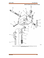
1
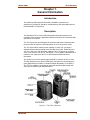
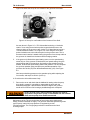
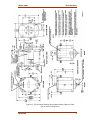
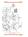
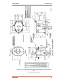
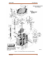
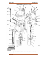
Installation and Operation Manual
TG-10 Governor
Manual 04041 (Revision J)
•
DEFINITIONS
•
•
•
•
This is the safety alert symbol. It is used to alert you to potential personal
injury hazards. Obey all safety messages that follow this symbol to avoid
possible injury or death.
DANGER—Indicates a hazardous situation which, if not avoided, will result in death
or serious injury.
WARNING—Indicates a hazardous situation which, if not avoided, could result in
death or serious injury.
CAUTION—Indicates a hazardous situation which, if not avoided, could result in
minor or moderate injury.
NOTICE—Indicates a hazard that could result in property damage only (including
damage to the control).
IMPORTANT—Designates an operating tip or maintenance suggestion.
The engine, turbine, or other type of prime mover should be equipped with an
overspeed shutdown device to protect against runaway or damage to the prime
mover with possible personal injury, loss of life, or property damage.
The overspeed shutdown device must be totally independent of the prime mover
control system. An overtemperature or overpressure shutdown device may also
be needed for safety, as appropriate.
Read this entire manual and all other publications pertaining to the work to be performed before
installing, operating, or servicing this equipment. Practice all plant and safety instructions and
precautions. Failure to follow instructions can cause personal injury and/or property damage.
This publication may have been revised or updated since this copy was produced. To verify that
you have the latest revision, be sure to check the Woodward website:
www.woodward.com/pubs/current.pdf
The revision level is shown at the bottom of the front cover after the publication number. The latest
version of most publications is available at:
www.woodward.com/publications
If your publication is not there, please contact your customer service representative to get the
latest copy.
Any unauthorized modifications to or use of this equipment outside its specified mechanical,
electrical, or other operating limits may cause personal injury and/or property damage, including
damage to the equipment. Any such unauthorized modifications: (i) constitute "misuse" and/or
"negligence" within the meaning of the product warranty thereby excluding warranty coverage
for any resulting damage, and (ii) invalidate product certifications or listings.
To prevent damage to a control system that uses an alternator or battery-charging
device, make sure the charging device is turned off before disconnecting the battery
from the system.
To prevent damage to electronic components caused by improper handling, read
and observe the precautions in Woodward manual 82715, Guide for Handling and
Protection of Electronic Controls, Printed Circuit Boards, and Modules.
Revisions—Text changes are indicated by a black line alongside the text.
Woodward Governor Company reserves the right to update any portion of this publication at any time. Information
provided by Woodward Governor Company is believed to be correct and reliable. However, no responsibility is assumed
by Woodward Governor Company unless otherwise expressly undertaken.
© Woodward 1978
All Rights Reserved
Manual 04041
TG-10 Governor
Contents
CHAPTER 1. GENERAL INFORMATION ........................................................... 1 Introduction .............................................................................................................1 Description ..............................................................................................................1 References .............................................................................................................3 CHAPTER 2. INSTALLATION.......................................................................... 4 Introduction .............................................................................................................4 Receiving ................................................................................................................4 Storage ...................................................................................................................4 Drive Shaft Rotation ...............................................................................................5 Changing Drive Shaft Rotation ...............................................................................5 Governor Mounting ...............................................................................................13 Linkage Attachments ............................................................................................14 Heat Exchanger Installation (optional) .................................................................14 Oil Supply .............................................................................................................15 When is a Heat Exchanger Necessary? ...............................................................18 CHAPTER 3. GOVERNOR OPERATION AND ADJUSTMENTS .......................... 19 Introduction ...........................................................................................................19 Initial Operation ....................................................................................................19 Speed Droop ........................................................................................................20 Droop Adjustment .................................................................................................20 CHAPTER 4. PRINCIPLES OF OPERATION ................................................... 22 Introduction ...........................................................................................................22 Description Of Operation ......................................................................................23 CHAPTER 5. TROUBLESHOOTING ............................................................... 26 Introduction ...........................................................................................................26 Visual Inspection ..................................................................................................26 Definitions .............................................................................................................26 CHAPTER 6. REPLACEMENT PARTS ........................................................... 29 Replacement Parts Information ............................................................................29 CHAPTER 7. SERVICE OPTIONS ................................................................. 38 Product Service Options .......................................................................................38 Woodward Factory Servicing Options ..................................................................39 Returning Equipment for Repair ...........................................................................40 Replacement Parts ...............................................................................................40 Engineering Services............................................................................................41 How to Contact Woodward ...................................................................................41 Technical Assistance ............................................................................................42 Woodward
i
TG-10 Governor
Manual 04041
Illustrations and Tables
Figure 1-1. The TG-10 Governor ............................................................................1 Figure 1-2. Governor Work Output .........................................................................2 Figure 2-1. Pump Housing Assembly .....................................................................5 Figure 2-2. Pump Housing Assembly .....................................................................6 Figure 2-3. Location of Pump Drive Pin .................................................................6 Figure 2-4. Pump Housing Assembly .....................................................................7 Figure 2-5. Set-up for cw Rotation of the Governor Drive Shaft ............................7 Figure 2-6. Set-up for ccw Rotation of the Governor Drive Shaft ...........................8 Figure 2-7. TG-10 Outline Drawing–Screw Speed Setting; Cast-Iron Case ..........9 Figure 2-8. TG-10 Outline Drawing–Lever Speed Setting; Cast-Iron Case .........10 Figure 2-9. TG-10 Outline Drawing–Screw Speed Setting; Die-Cast Aluminum
Case.................................................................................................11 Figure 2-10. TG-10 Outline Drawing–Lever Speed Setting; Die-Cast Aluminum
Case.................................................................................................12 Figure 2-11. Heat Exchanger Tap Locations........................................................14 Figure 2-12. Heat Exchanger Piping Schematic ..................................................15 Figure 3-1. Droop Adjusting Lever Movement......................................................21 Figure 4-1. TG-10 Schematic Diagram ................................................................22 Figure 4-2. TG-10 Schematic Diagram ................................................................25 Figure 6-1. TG-10 Parts–Cast-Iron Case; Screw Speed Setting .........................31 Figure 6-2. TG-10 Parts–Cover Assembly (Lever Speed Setting) for Use with
Cast-Iron Case TG-10 .....................................................................33 Figure 6-3. TG-10 Parts–Die-Cast Aluminum Case; Screw Speed Setting .........35 Figure 6-4. TG-10 Parts–Cover Assembly (Lever Speed Setting) for Use with
Aluminum Case TG-10 ....................................................................37 Table 2-1. Oil Chart ..............................................................................................16 Table 2-2. Viscosity Comparisons ........................................................................16 Table 5-1. TG-10 Troubleshooting .......................................................................27 ii
Woodward
Manual 04041
TG-10 Governor
Chapter 1.
General Information
Introduction
This manual provides general information, installation, operation and
adjustments, principles of operation, troubleshooting, and replaceable parts for
the Woodward TG-10 governor.
Description
The Woodward TG-10 is a mechanical-hydraulic speed droop governor for
controlling steam turbines—applications where isochronous (or constant-speed)
operation is not required.
The TG-10 governor has 32 degrees of maximum shaft travel. Recommended
travel from the no-load to the full-load position is 2/3 of full governor travel.
The TG-10 provides a maximum work capacity of 10 ft-lb (14 J) through a
serrated terminal shaft extending from both sides of the case. Stalled torque is
175 lb-in (19.8 Nxm), and rated work capacity is 60 to 70 percent of maximum
work, not to exceed 7 ft-lb (9.5 J). See Figure 1-2 for a graphic representation of
maximum work capacity for the TG-10 and related terminal shaft travel
information.
The governor is set to the speed range specified by customer at time of order.
The high-speed governor (4000 to 6000 rpm) may require a heat exchanger in
some applications (see When is a Heat Exchanger Necessary? in Chapter 2).
The TG-10 is capable of controlling at lower-than-specified speed range with
some loss of output torque and performance.
Figure 1-1. The TG-10 Governor
Woodward
1
TG-10 Governor
Manual 04041
Figure 1-2. Governor Work Output
The TG-10 governor is available in two different types of construction, a cast-iron
case or a die-cast aluminum case.
Speed droop is required for stable governor operation and is factory set, but is
internally adjustable.
Two means of speed setting are available for the TG-10. Screw speed setting
with a cover-top adjusting screw is standard. Lever speed-setting is optional and
provided by a serrated shaft assembly extending from both sides of the cover.
The TG-10 governor is identified by the type of its cover assembly,
and is commonly referred to as a TG-10 or a TG-10 Lever.
Governor drive-shaft rotation is single direction only, but rotation is changeable in
the field by an internal adjustment on the cast-iron TG-10, and by an external
adjustment on the die-cast aluminum TG-10 (see Chapter 2). Clockwise (cw) or
counterclockwise (ccw) rotation is determined when viewing from the governor
top. On some models, direction of rotation is marked by a decal on the governor
side, on other models it is stamped cw or ccw on the governor nameplate.
The internal pump is sized to operate over standard speed ranges:
1100 to 2400 rpm
2400 to 4000 rpm
4000 to 6000 rpm
Maintenance of the TG-10 is minimal due to few moving parts, weatherproof
design, and self-contained oil supply. The governor drive shaft operates a
gerotor-type oil pump. Internal oil pump pressure is regulated by a relief
valve/accumulator. On some models, a single oil sight gauge can be installed on
either side of the governor case. On other models, an oil sight gauge is installed
on each side of the governor case. Either type of installation makes oil condition
and oil-level checking simple.
2
Woodward
Manual 04041
TG-10 Governor
References
The following publications may prove useful.
Number
25071
25075
36641
50014
50015
Woodward
Title
Oils for Hydraulic Controls
Commercial Preservation Packaging for Storage of MechanicalHydraulic Controls
Governor Oil Heat Exchanger
Service Bulletin, describes the drilling of an oil relief hole in the
TG-10 pump housing not previously modified to reduce seal wear
Service Bulletin, describes the drilling and tapping of a hole in TG-10
cases not previously modified for the addition of an oil cooler
3
TG-10 Governor
Manual 04041
Chapter 2.
Installation
Introduction
Use care while handling and installing the TG-10. Be particularly careful to avoid
striking the drive shaft, terminal shafts, and speed setting shafts or adjusting
screw. Abuse can damage seals, internal parts, and factory adjustments.
Do not rest the governor on its drive shaft.
The engine, turbine, or other type of prime mover should be
equipped with an overspeed shutdown device to protect against
runaway or damage to the prime mover with possible personal injury,
loss of life, or property damage.
The overspeed shutdown device must be totally independent of the
prime mover control system. An overtemperature or overpressure
shutdown device may also be needed for safety, as appropriate.
Receiving
The TG-10 is shipped from the factory bolted to a wooden platform in the vertical
position and boxed. The oil sight gauge is factory installed on the left side of the
case, and a breather/filler cap is positioned for vertical governor mounting and
operation. On late TG-10 models, an oil sight gauge is installed on each side of
the case.
After factory testing and adjusting, the TG-10 is drained of oil, sealed, and
painted. This leaves a light film of oil covering internal parts to prevent rust.
External shafts are coated with a spray lubricant. No internal cleaning or flushing
is necessary before installation and operation or customer retesting.
Storage
The TG-10 may be stored for short periods of time as received from the factory.
For long term storage in a hostile environment (large temperature changes,
humid or corrosive atmosphere), or if the governor is installed on the turbine for
storage, fill the governor with oil and follow preservation packaging instructions in
Woodward manual 25075, Commercial Preservation Packaging for Storage of
Mechanical-Hydraulic Controls.
If the breather/filler cap has been moved for horizontal governor operation and
the governor is to be stored vertically, replace the cap with a plug before filling
the governor with oil to prevent oil from draining through the cap.
4
Woodward
Manual 04041
TG-10 Governor
Drive Shaft Rotation
Governor drive shaft rotation for Woodward governors is determined when
looking at the governor from the top.
The correct direction of rotation of the TG-10, when viewed from the
top of the governor, is stamped “cw” or “ccw” on the governor
nameplate.
Governor drive shaft rotation is single direction only. When looking at the
governor from the top, the direction of rotation must be the same as the turbine
shaft rotation when looking at the mounting pad.
If the governor oil pump is rotated in the wrong direction, oil pressure is no longer
generated. Pump parts start heating up, which can result in possible seizure of
rotating parts.
Be sure governor drive and turbine drive rotation is the same when
looking at the governor and the mounting pad from the top. Incorrect
drive rotation may cause governor damage.
Changing Drive Shaft Rotation
TG-10 with a Pump Eccentric not Machined into the Base
See Figure 2-1. Use the following procedure:
1.
See Figures 2-1, 2-2, and 2-3.
2.
Remove the governor from the turbine. Drain the oil from the governor.
3.
Place the governor on its side with the cooler tap up.
4.
Turn the key slot on the drive shaft to face up.
5.
Remove the four pump housing screws and remove the pump housing.
6.
Notice the directional arrows stamped on the pump housing. Turn the
eccentric ring so the pin hole is next to the arrow for desired shaft rotation.
Figure 2-1. Pump Housing Assembly
7.
Woodward
Insert the pin into the pin hole in the eccentric (pin must drop below flush).
5
TG-10 Governor
8.
Manual 04041
Place the inner and outer gear in the pump housing.
Figure 2-2. Pump Housing Assembly
9.
Be sure the key slot in the drive shaft is turned up and the square headed
pump drive pin is in place.
10. Install the pump housing assembly on the drive shaft and align the slot in
the inner gear with the pump drive pin.
Do not turn the drive shaft in order to engage the outer and inner
pump gears. It is possible for the pump drive pin to fall out if the
drive shaft is turned. The square head on the pump drive pin must
remain against the case bottom as shown in Figure 2-3.
Figure 2-3. Location of Pump Drive Pin
11. Fasten the pump housing to the case with four screws and torque to 300
lb-in (34 Nxm).
12. Check that the drive shaft rotates freely.
13. Place the ballhead retaining collar on the drive shaft. Leave 0.010 inch (0.25
mm) clearance between the pump housing and collar. Torque to 50 lb-in
(5.6 Nxm).
If the drive shaft does not rotate freely, loosen the four pump
housing screws, align the pump, and tighten the screws.
6
Woodward
Manual 04041
TG-10 Governor
TG-10 with a Pump Eccentric Machined into the Base
See Figure 2-4. Use the following procedure:
1.
See Figures 2-4 and 2-5.
2.
Remove the four pump housing screws.
Hold the pump housing assembly flat against the governor case
when rotating pump housing 180 degrees (see WARNING below).
Figure 2-4. Pump Housing Assembly
3.
Rotate the pump housing assembly 180°.
4.
Align the arrow on the pump housing with the reference point on the
governor case. Figure 2-5 shows the set-up for cw rotation of the governor
drive shaft.
Figure 2-5. Set-up for cw Rotation of the Governor Drive Shaft
Woodward
7
TG-10 Governor
Manual 04041
Figure 2-6 shows the set-up for ccw rotation of the governor drive shaft.
Figure 2-6. Set-up for ccw Rotation of the Governor Drive Shaft
As seen above in Figure 2-5, a TG-10 described as having a “clockwise
rotation” is set using the arrow that points counterclockwise next to the
reference point on the governor case. And a TG-10 described as having a
“counterclockwise rotation”, as in Figure 2-6, is set using the arrow that
points clockwise next to the reference point on the governor case. This is
because normal rotation is stated viewing the governor from the top and that
the governor is viewed from the bottom while changing rotation.
5.
If the governor is fitted with a speed setting screw, turn the speed setting
screw fully cw. If the governor is fitted with a lever speed setting, bring the
speed setting shaft to the maximum fuel position using serration wrench
030943, and hold the speed setting shaft in that position. This will compress
the governor speeder spring and prevent a possible separation of the
governor drive shaft (124) from the ballhead assembly (123). See Figure
6-3.
Now keep maintaining pressure on the speeder spring while replacing the
four screws, and torque to 80 lb-in (9.0 Nxm).
6. Check that the drive shaft rotates freely.
7.
Remove the cover and check that the ballhead is rotating when the pump
drive shaft is rotated. It is possible to reassemble the pump with the
ballhead disengaged. If this should be allowed to happen, the governor
would call for maximum fuel causing a possible dangerous overspeed.
Death, personal injury and/or extensive damage can result to
equipment if the governor pump is reassembled with the ballhead
shaft and the pump drive shaft disconnected.
Maintenance of the TG-l0 is minimal due to few moving parts, weatherproof
design, and self contained oil supply. The governor drive shaft operates a gerotor
type oil pump. Internal oil pump pressure is regulated by a relief
valve/accumulator. The oil sight gauge makes oil conditions and oil level
checking simple.
8
Woodward
Manual 04041
TG-10 Governor
Figure 2-7. TG-10 Outline Drawing–Screw Speed Setting; Cast-Iron Case
(Do not use for construction.)
Woodward
9
TG-10 Governor
Manual 04041
Figure 2-8. TG-10 Outline Drawing–Lever Speed Setting; Cast-Iron Case
(Do not use for construction.)
10
Woodward
Manual 04041
TG-10 Governor
Figure 2-9. TG-10 Outline Drawing–Screw Speed Setting; Die-Cast Aluminum
Case
(Do not use for construction.)
Woodward
11
TG-10 Governor
Manual 04041
Figure 2-10. TG-10 Outline Drawing–Lever Speed Setting; Die-Cast Aluminum
Case
(Do not use for construction.)
12
Woodward
Manual 04041
TG-10 Governor
Governor Mounting
This governor can be mounted either vertically or horizontally. Mounting is called
vertical or horizontal if the drive shaft is in a vertical or horizontal position when
viewing the governor installed on its mounting base.
The breather/filler cap and the drain plug are factory installed for vertical
governor operation. For horizontal operation, the cap and drain plug must be
moved to their alternate positions. This places the servo piston on the bottom,
keeping it completely immersed in oil and preventing air from being trapped in
the servo. See outline drawings, Figures 2-7, 2-8, 2-9, and 2-10, for alternate cap
and plug positions as well as governor mounting hole locations and hole sizes.
The oil sight gauge may be moved to the right side, if desirable.
For horizontal operation, the TG governor must be installed with the
oil sight gauge at the top of the governor, as shown in the outline
drawings.
Make sure there is adequate clearance for attaching the fuel control or steam
valve linkage, manual speed adjustment or speed setting lever linkage, and for
oil maintenance.
The governor requires 1/2 hp (373 W) maximum to turn the drive shaft at rated
speed. A decal on the side of the case indicates the direction of rotation when
shipped from the factory. On later TG-10 models, the correct direction of rotation
is stamped “cw” or “ccw” on the governor nameplate. (Governor drive shaft
rotation for Woodward governors is determined when looking at the governor
from the top).
Be sure turbine drive and governor drive directions of rotation are
the same. Incorrect drive rotation may cause governor damage.
Make sure the drive shaft turns freely before installing the TG-10. Mount the
governor squarely on the mounting pad, installing the correct length coupling with
a number 5 Woodruff key. Use a gasket between the governor and the engine
mounting pad. There must be no binding, side loading, or backlash in the
governor drive. Improper alignment or too tight a fit between parts can result in
excessive wear or seizure and may also cause undesirable “jiggle”, noticeable at
governor output during operation. There must be no force pushing the drive shaft
into the governor. Tighten the four governor mounting bolts equally.
Woodward
13
TG-10 Governor
Manual 04041
Linkage Attachments
Terminal Shaft
The terminal shaft extends from both sides of the case and provides 30° travel.
20° travel is recommended between no load and full load. Installed linkages must
operate smoothly, free of binding, and can be spring loaded in the shutdown
direction only to remove looseness.
Be sure to allow sufficient overtravel at each end of the terminal
shaft so the governor can create a shutdown and also give maximum
steam flow when required. Failure to provide sufficient overtravel at
minimum fuel position can prevent the governor from shutting down
the prime mover and result in possible damage to equipment and
personal injury.
Speed Setting Linkage
If the TG-10 is equipped with optional lever speed setting, linkage to the speed
setting shaft on either side must be installed. Lever speed setting requires 30°
travel for full governor speed range. An internal return spring force on the speed
setting shaft is 22 lb-in (2.5 Nxm) maximum. Speed setting linkage must also
operate smoothly, without binding or looseness.
Heat Exchanger Installation (optional)
If it is necessary to install a heat exchanger, mount it below governor oil level in
order to prevent overflow of oil through the governor breather/filler cap. Flush the
heat exchanger before installation. Make the required piping connections to the
cooler and the governor. See Figures 2-7, 2-8, 2-9, and 2-10, which illustrate tap
locations and piping connections. Notice in Figure 2-11, Heat Exchanger Tap
Locations, that there are two tap locations for the oil from cooler outlet. Which tap
location is used depends on the governor mounting position.
Figure 2-11. Heat Exchanger Tap Locations
14
Woodward
Manual 04041
TG-10 Governor
Figure 2-12. Heat Exchanger Piping Schematic
TG-10 governors assembled after October 1976 have been factory drilled and
tapped with the oil to cooler inlet so the cooler can be easily added. TG-10
governors assembled without this factory tapped hole must be drilled and tapped,
per Woodward TG-10 Service Manual 50015, before a cooler can be added. See
Figure 2-11 for the approximate location of this tapped hole.
Pipe must be sized to minimize pipe pressure losses which must not exceed 15
psi (103 kPa). Oil flow from the oil to cooler inlet tap (0.125”-27 NPTF) on a
governor operating at 6000 rpm and using a 0.188 thick gerotor pump (0.188 is
standard thickness on high-speed governors) is 1 US gal/min (3.8 L/min) at 150
psi (1034 kPa). Install a governor oil drain in the oil from cooler outlet pipe at the
lowest point in the system. See Figure 2-12.
It is recommended that a throttling device be installed so that coolant flow to the
heat exchanger can be regulated for optimum oil operating temperature.
Excessive cooling of governor oil can cause marginal operation.
Oil Supply
Remove the breather/filler cap and fill the governor with 1.75 qt (1.7 L) of oil to a
level visible on the oil sight gauge. Additional oil is required if the governor uses
an oil heat exchanger. Always check that the oil level is visible on the oil sight
gauge before starting. After the engine is started and the governor is at operating
temperature, add oil if necessary.
Use an oil depending on operating temperature for the governor (see Table 2-1).
Primary concern is for the oil properties in the governor.
Use the information given in Tables 2-1 and 2-2 as a guide in the selection of a
suitable lubricating! hydraulic oil. Oil grade selection is based on the operating
temperature range of the governor. Also, use this information to aid in
recognizing and correcting common problems associated with oil used in
products manufactured by Woodward.
Woodward
15
TG-10 Governor
Manual 04041
Table 2-1. Oil Chart
Table 2-2. Viscosity Comparisons
16
Woodward
Manual 04041
TG-10 Governor
For applications where the governor shares the oil supply with the engine, use
the oil recommended by the engine manufacturer.
Governor oil is both a lubricating oil and a hydraulic oil. It must have a viscosity
index that allows it to perform over the operating temperature range, and it must
have the proper blending of additives that cause it to remain stable and
predictable over this range.
Governor oil must be compatible with seal materials (nitrile, polyacrylic, and
fluorocarbon). Many automotive and gas engine oils, industrial lubricating oils,
and other oils of mineral or synthetic origin meet these requirements.
Woodward governors are designed to give stable operation with most oils with
the viscosity, at the operating temperature, between 50 and 3000 SUS (Saybolt
Universal Seconds). At the normal operating temperature, the viscosity should be
between 100 to 300 SUS. Poor actuator response or instability may be an
indication that the oil viscosity is outside this range.
Excessive component wear or seizure in a governor indicates the possibility of:
1.
Insufficient lubrication caused by:
a. An oil that flows slowly when it is cold, especially during start-up.
b. An oil line with restrictions caused by either obstructions within or
bends in the line (for external supply governors only).
c. No oil in the governor.
2.
Contaminated oil caused by:
a. Dirty oil containers.
b. A governor exposed to heating up and cooling down cycles, which
creates condensation of water in the oil.
3.
Oil not suitable for the operating conditions caused by:
a. Changes in ambient temperature.
b. An improper oil level which creates foamy, aerated oil.
Operating a governor continuously beyond the high limit temperature of the oil
will result in oil oxidation. This is identified by varnish or sludge deposits on the
governor parts. To reduce oil oxidation, lower the actuator operating temperature
with a heat exchanger or other means, or change to an oil more oxidationresistant at the operating temperature.
A loss of stable governor control and possible engine overspeed
may result If the viscosity exceeds the 50 to 3000 SUS range.
Specific oil viscosity recommendations are given on the Oil Chart (Table 2-1).
Select a readily available good brand of oil, either mineral or synthetic, and
continue using that same brand. Do NOT mix different classes of oils. Oil that
meets the API (American Petroleum Institute) engine service classification in
either the “S” group or the “C” group, starting with “SA” or “CA” through “SF” and
“CD” is suitable for governor service. Oils meeting performance requirements of
the following specifications are also suitable: US MIL-L-2104A, MIL-L-2104B,
MlL-L-2104C, MIL-L-46152, MIL-L-46152A, MIL-L-46152B, MIL-L-45199B.
Woodward
17
TG-10 Governor
Manual 04041
Replace the governor oil if it is contaminated, also change it if it is suspected of
contributing to governor instability. Drain the oil while it is still hot and agitated;
flush the governor with a clean solvent having some lubricity (such as fuel oil or
kerosene) before refilling with new oil. If drain time is insufficient for the solvent to
completely drain or evaporate, flush the governor with the same oil it is being
refilled with to avoid dilution and possible contamination of the new oil. To avoid
recontamination, the replacement oil should be free of dirt, water, and other
foreign material. Use clean containers to store and transfer oil.
Observe manufacturer’s instructions or restrictions regarding the
use of solvents. If no instructions are available, handle with care. Use
the cleaning solvent in a well ventilated area away from fires or
sparks.
Oil that has been carefully selected to match the operating conditions and is
compatible with governor components should give long service between oil
changes. For governors operating under ideal conditions (minimum exposure to
dust and water and within the temperature limits of the oil), oil changes can be
extended. If available, a regularly scheduled oil analysis is helpful in determining
the frequency of oil changes.
Any persistent or reoccurring oil problems should be referred to a qualified oil
specialist for solution. The recommended continuous operating temperature of
the oil is 140 to 200 °F (60 to 93 °C). The ambient temperature limits are –20 to
+200 °F (–29 to +93 °C). Measure the temperature of the governor on the outside
lower part of the case. The actual oil temperature will be slightly warmer, by
approximately 10 °F (6 °C).
When is a Heat Exchanger Necessary?
Some applications of the TG-10 may require an oil heat exchanger be used to
prevent oil breakdown and subsequent problems due to excessive oil operating
temperatures. TG-10 governors operating at low and medium speed ranges
(1100 to 2400 rpm and 2400 to 4000 rpm) do not normally require one to be
used. The high-speed governor (4000 to 6000 rpm) may require a heat
exchanger in some applications. Factors such as oil viscosity, governor speed,
heat radiation from surrounding sources, and mounting pad and ambient
temperatures affect oil conditions necessitating an oil cooler. See Woodward
manual 25071, Oils for Hydraulic Controls. Generally, whenever operating oil
exceeds its recommended viscosity/operating temperature range, or when oil
viscosity at operating temperature is below 100 SUS, an oil cooler may be
required. Late model TG-10 governors are equipped with a cooler tap.
Under laboratory test conditions, a single pass, counter-flow heat exchanger with
1 to 2 ft² (0.09 to 0.19 m²) of effective heat transfer area provides adequate
cooling for most high-speed TG-10 governor applications. If there is doubt
concerning the need for, or size of, a heat exchanger, contact Woodward.
18
Woodward
Manual 04041
TG-10 Governor
Chapter 3.
Governor Operation and Adjustments
Introduction
This chapter provides initial operating instructions and adjustment features of the
TG-10 governor.
The engine, turbine, or other type of prime mover should be
equipped with an overspeed shutdown device to protect against
runaway or damage to the prime mover with possible personal injury,
loss of life, or property damage.
The overspeed shutdown device must be totally independent of the
prime mover control system. An overtemperature or overpressure
shutdown device may also be needed for safety, as appropriate.
Initial Operation
Before initial operation of the TG-10 equipped turbine, check that all previous
installation steps are successfully accomplished.
Be prepared to make an emergency shutdown when starting the
engine, turbine, or other type of prime mover, to protect against
runaway or overspeed with possible personal injury, loss of life, or
property damage.
Normally, the only requirements for putting a new or overhauled governor into
service are to fill the governor with oil and adjust the rated speed setting. All
other adjustments are accomplished during factory testing according to the
turbine manufacturer specifications and should not require further adjustments.
Governor speed setting is factory set to give rated speed at initial start-up. If
desired, the speed setting may be decreased before start-up by the manual
speed setting screw, or by turning the high-speed stop screw cw on lever speed
setting models to give low speed at initial start-up.
Open the steam valve slowly. Check the turbine speed and adjust as necessary
to bring the turbine to rated speed. Make sure the terminal shaft linkage to the
valve is correctly adjusted to allow maximum and minimum steam flow
requirement.
Check the governor for stable operation by manually disturbing the terminal shaft
linkage or speed setting. Governor stability is satisfactory when the governor
returns to speed with only a slight over or undershoot. Instability indicates the
need for adjustment of droop.
Woodward
19
TG-10 Governor
Manual 04041
Speed Droop
Speed droop or simply droop is the simplest method of creating stability in a
governor. It is the decrease in speed taking place when the governor terminal
shaft moves from the minimum to the maximum fuel position in response to a
load increase, expressed as a percentage of rated speed.
If instead of a decrease in speed, an increase takes place, the governor is
showing a negative droop. Negative droop will cause instability in a governor.
Not enough droop can cause instability in the form of hunting, surging, or
difficulty in response to a load change. Too much droop can result in slow
governor response in picking up or dropping off a load. Droop can be calculated
with the following formula:
% Droop =
No Load Speed – Full Load Speed
Full Load Speed
x 100
Droop Adjustment
The factory-made 6% droop setting for 20° terminal shaft travel will provide
sufficient stability for most applications and will not normally need to be adjusted
before governor operation. Adjustment may be necessary if the governor has
been disassembled.
If the governor terminal shaft does not use the full 20° of available
travel from “NO LOAD” to “FULL LOAD,” droop will also be reduced
proportionately.
Adjustment of droop is indicated during governor operation by instability, or
difficulty in responding to a load change. Instability, in the form of hunting or
surging, indicates insufficient droop, and the droop adjusting lever should be
positioned to increase droop. If the TG-10 shows difficulty in accepting load, or
where the governor becomes unstable after a load change, excessive droop is
indicated. In cases where the droop setting of the governor must be changed on
the engine, use the following droop adjusting procedure:
1.
The cover assembly must be removed to gain access to the droop adjusting
lever. Use care while removing the cover not to damage the cover gasket. If
the governor is horizontally mounted, drain governor oil before removing the
cover. The cover also fastens internal parts that can fall out, especially on
horizontally mounted governors.
2.
Loosen the socket head screw which fastens the droop adjusting lever just
enough to slide the lever a very small amount, approximately 1/32” (0.8 mm)
at a time, in the direction desired to adjust droop.
Moving the droop adjusting lever away or towards the terminal shaft center
line increases or decreases droop respectively (see Figure 3-1).
3.
20
Tighten the screw, install the cover, and fill with oil to the correct level.
Woodward
Manual 04041
TG-10 Governor
Do not move the droop adjusting lever in the decrease droop
direction past the point of zero droop (the center line of the terminal
shaft), as this results in a speed Increase in response to a load
increase and a subsequent, unstable operation.
Figure 3-1. Droop Adjusting Lever Movement
4.
Observe governor operating behavior again and repeat adjustments to the
droop adjusting lever until governor operation is satisfactory. If repeated
attempts at adjustment fail to provide governor stability, other problems are
indicated. See Troubleshooting Table 5-1.
Do not operate the TG-10 without the cover assembly securely In
place.
Woodward
21
TG-10 Governor
Manual 04041
Chapter 4.
Principles of Operation
Introduction
This chapter describes the operation of the TG-10 governor. This includes an
explanation of the hydraulic system and the way oil is distributed. A description of
the ballhead assembly, pilot valve function, and the droop slider concludes this
chapter.
Internally, the TG-10 governor consists of the following basic items:
•
oil pump
•
oil accumulator
•
speeder spring
•
ballhead and pilot valve bushing assembly
•
pilot valve plunger
•
servo piston
•
droop adjustment
•
speed adjustment
•
terminal lever and shafts
A schematic diagram (Figure 4-1) shows the relationship of these various items
and provides a visual means of understanding the operation of the TG-10
governor.
Figure 4-1. TG-10 Schematic Diagram
22
Woodward
Manual 04041
TG-10 Governor
Description Of Operation
Oil Pressure And Distribution
The governor is normally driven by the turbine through a flexible coupling. The
inner gerotor of the oil pump is keyed to the governor drive shaft and pilot valve
bushing. The pump draws oil from the sump and distributes it through the oil
passages within the case. Oil is also discharged to the spring-loaded
accumulator. The accumulator maintains the 150 psi (1034 kPa) operating
pressure at rated speed. Excess pressure compresses the accumulator springs,
and oil is released to sump during steady state operation.
A change in speed and centrifugal force moves the flyweights out or in. This
moves the pilot valve plunger either upward or downward depending on whether
it is an increase or decrease in speed. Plunger movement opens the control port
and releases oil either to sump or to the underside of the servo piston. During
servo piston movement in the increase fuel direction, the accumulator
supplements the system oil supply with its stored volume of high pressure oil and
helps maintain the full work capacity of the governor.
Ballhead Operation
The ballhead assembly contains two flyweights, speeder spring, thrust bearing,
pilot valve plunger, and pilot valve bushing. As the flyweights are rotated, they
produce a centrifugal force that is opposed by the downward force of the speeder
spring. The speeder spring force can be varied by adjusting the speed setting
screw, or speed setting lever.
A thrust bearing on top of the flyweight toes permits the pilot valve bushing to
rotate around the pilot valve plunger. This reduces static friction between the
bushing and plunger.
Pilot Valve Function
When the turbine is running on-speed, the pilot valve plunger is centered,
covering the control ports of the pilot valve bushing. In this position, no oil is
discharged from, or flows to, the servo piston, and the governor terminal shaft
cannot move. A change in either the flyweight centrifugal force or the speeder
spring force (speed setting) moves the plunger from its centered position
controlling oil flow at the servo piston and moves the servo piston.
The pilot valve plunger lowers if:
1.
An additional load slows the turbine and governor speed. This decreases
the centrifugal force of the rotating flyweights which oppose the force of the
speeder spring.
2.
The turbine speed is unchanged, but speeder spring force is increased by
raising the governor speed setting with the speed setting screw or speed
setting lever.
Lowering the pilot valve plunger control land opens the control ports. High
pressure oil is released to the area below the servo piston forcing the servo
piston upwards. This rotates the governor terminal shaft in the increase steam
direction.
Woodward
23
TG-10 Governor
Manual 04041
As the servo piston rises, the speeder spring force is decreased by movement of
the terminal lever and allows the pilot valve plunger to rise. The flow of high
pressure oil to the servo piston is closed off by the control land, stopping the
upward motion of the servo piston.
The pilot valve plunger raises if:
1.
The centrifugal force of the rotating flyweights is increased by a load
decrease on the turbine. This causes an increase in turbine and governor
speed.
2.
The governor speed is lowered by reducing the speeder spring force with
the speed adjusting screw.
Raising the pilot valve plunger control land again opens the ports, but this time
control oil is released to sump from below the servo piston. High pressure oil in
the area above the servo piston cylinder forces the piston down. This rotates the
terminal shaft in the decrease steam or fuel direction. Speeder spring pressure
increases forcing the pilot valve plunger downward. Terminal shaft movement
stops as the control land covers the ports stopping the release of control oil.
Droop Adjusting Lever Function
Note that as the terminal lever rotates in the increase fuel direction, the droop
adjusting lever is lifted and decreases the speeder spring force on the flyweights.
Thus, the ballhead is allowed to re-center the pilot valve plunger at lower speeds
as fuel is increased. This characteristic is referred to as “speed droop”. Closing
the control port stops further movement of the servo piston simultaneously with
the return of engine speed to a speed determined by the new speed or spring
force.
When moving in the decrease fuel direction, the terminal lever lowers the droop
adjusting lever and increases the speeder spring force. This increase in speeder
spring force re-centers the pilot valve plunger and stops further servo piston
movement.
The amount of speed change, or droop, for a given amount of terminal shaft
rotation depends upon the positioning of the droop adjusting lever on the terminal
lever.
24
Woodward
Manual 04041
TG-10 Governor
Figure 4-2. TG-10 Schematic Diagram
Woodward
25
TG-10 Governor
Manual 04041
Chapter 5.
Troubleshooting
Introduction
Faults in governor operation are usually revealed as speed variations of the
turbine. But, it cannot be assumed that all such variations indicate a fault in the
governor. Therefore, when improper operation is evident, check all components,
adjustment settings, and the turbine for correct operation.
Use the following troubleshooting table to isolate and remedy faults in the
governed system. When requesting additional information or service help from
Woodward or an authorized service shop, it is important to include in your
correspondence the governor part number, serial number, and a complete
description of all problems or symptoms.
The engine, turbine, or other type of prime mover should be
equipped with an overspeed shutdown device to protect against
runaway or damage to the prime mover with possible personal injury,
loss of life, or property damage.
The overspeed shutdown device must be totally independent of the
prime mover control system. An overtemperature or overpressure
shutdown device may also be needed for safety, as appropriate.
Visual Inspection
Before attempting to troubleshoot the system, visually check the following items:
1.
Check linkages installed between the governor output and a steam valve
and any speed setting linkage. Common sources of trouble are binding, lost
motion, or inadequate travel.
2.
Check the oil for proper level and good condition. Dirty oil causes many
governor troubles. Oil contaminated by water, or excessive heat, breaks
down rapidly, causing foaming and corroding of internal parts.
3.
Check for correct turbine operation. Be sure the drive to the governor drive
is smooth, free of torsional vibration.
4.
Be sure the speed variations are not the result of load changes beyond the
capacity of the turbine.
Definitions
Terms used in the troubleshooting chart are defined as follows:
HUNT
A rhythmic variation of speed which can originate in the governor or in the prime
mover. See Table 5-1, Paragraph 1 for Troubleshooting Information. A hunt
usually has a frequency of less than 50 cycles per minute.
26
Woodward
Manual 04041
TG-10 Governor
SURGE
A rhythmic variation of speed occurring at periodic intervals which can also
originate in the governor or in the prime mover. See Table 5-1, Paragraph 1 for
Troubleshooting Information.
JIGGLE
A high frequency vibration of the governor terminal shaft and fuel linkage. See
Table 5-1, Paragraph 2, for Troubleshooting information. Do not confuse this with
normal controlling action of the governor. A jiggle has a frequency of more than
50 cycles per minute.
Be prepared to make an emergency shutdown when starting the
engine, turbine, or other type of prime mover, to protect against
runaway or overspeed with possible personal injury, loss of life, or
property damage.
Table 5-1. TG-10 Troubleshooting
Symptom
1.
The turbine hunts
or surges.
2.
Governor terminal
shaft jiggles.
3.
The governor
shows difficulty in
accepting load, or
is unstable as
evidenced by a
slow and unsteady
oscillation,
especially after a
load change.
4.
The turbine does
not pick up rated
full load.
Woodward
Cause
A. Low oil level.
Correction
Add oil to a level visible in the oil sight gauge.
B.
Remove and flush with light weight oil.
Dirt in governor.
C. Binding terminal shaft
linkage.
Re-align linkage as necessary. If governor was recently
disassembled, check that terminal shaft bearings do not
bind internally on the terminal lever.
D. Insufficient droop
adjustment.
A. Improper alignment of
the governor drive coupling.
Reposition droop adjusting lever to increase droop.
B. Worn flyweight pins.
A. Insufficient use of
terminal shaft travel.
Return Governor to factory for repair.
Check linkage. Recommended travel is 20° from no load to
full load.
Check and repair as necessary.
NOTE—Droop and its stabilizing effect are a function of
governor terminal shaft travel. If the governor terminal shaft
linkage is arranged so that only a small percentage of
terminal shaft travel is used from no load to full load, droop
and its stabilizing effect is reduced proportionately.
B.
Too much droop.
Re-position the droop adjusting lever for decreased droop
compensation.
C.
High steam valve gain.
Check that steam valve is not too large or oversize for the
particular application.
D.
A.
Dirt in governor oil.
Speed setting too low.
Drain, flush, and refill with fresh oil.
Increase governor speed setting.
27
TG-10 Governor
Symptom
5.
The turbine does
not pick up rated
full load.
6.
7.
The governor does
not start or control.
Governor starts,
but remains at
maximum.
28
Manual 04041
Cause
B. Incorrect terminal shaft
linkage travel.
Correction
Check linkage. Recommended travel is 20 0 from no load to
full load.
C. Governor speed range is
incorrect for the particular
application.
Check speed range of the governor.
D. Droop setting too high.
A. Wrong governor drive
rotation.
Re-position the droop adjusting lever to decrease droop.
Check turbine drive to the governor. Reverse pump parts for
different rotation if necessary.
B. Woodruff key not
properly installed or missing,
drive shaft is not engaged.
Check drive installation.
C.
A.
Return governor to factory for repair.
Reduce speed setting until governor controls, then adjust for
desired speed.
Pump drive pin is broken.
Speed setting too high.
Woodward
Manual 04041
TG-10 Governor
Chapter 6.
Replacement Parts
Replacement Parts Information
When ordering replacement parts, include the following information:
1. Governor serial number and part number shown on nameplate.
2. Manual number (this manual 04041).
3. Parts reference number in parts list and description of part or part name.
Locations of Woodward plants and Woodard authorized repair facilities are listed
on the Woodward website (www.woodward.com).
Refer to Repair Manual 56101 for correct and safe procedures when
disassembly and assembly are required.
Replacement Parts List For Figure 6-1
Ref No.
04041-1
04041-2
04041-3
04041-4
04041-5
04041-6
04041-7
04041-8
04041-9
04041-9A
04041-9B
04041-10
04041-11
04041-12
04041-13
04041-14
04041-15
04041-16
04041-17
04041-18
04041-19
04041-20
04041-21
04041-22
04041-23
04041-24
04041-25
04041-26
04041-26A
04041-27
04041-28
04041-28A
04041-29
04041-30
Woodward
Part Name ............................................................. Quantity
Drive screw .........................................................................2
Governor nameplate ...........................................................1
Breather/Filler cap ..............................................................1
Cover (for screw speed setting) ..........................................1
Cover gasket.......................................................................1
Screw, soc hd .250-20 x 1.00” ............................................3
Flatwasher, .265 x .500” .....................................................1
Droop adjusting lever ..........................................................1
Screw, soc hd sems .250 - 20 x 2.00 .................................2
Washer, .250 Internal shakeproof ......................................2
Washer, .265 x .500 x .064 thick ........................................2
Connecting link (chain link) .................................................1
Servo piston bushing ..........................................................1
Servo piston ........................................................................1
Straight pin ..........................................................................1
Preformed packing ring, 2.114 ID x .070 ............................1
Gerotor oil pump .................................................................1
Pump spacers .................................. (use none, 1, or 2, AR)
Pump housing .....................................................................1
Taper pin, #5 .......................................................................2
Oil seal ................................................................................1
Ballhead retainer collar .......................................................1
Screw, soc hd sems .312-18 x 1.00” ..................................4
Terminal shaft .....................................................................2
Oil seal ................................................................................2
Roller bearing .....................................................................2
Pipe plug, .062-27 NPTF ....................................................1
Pipe plug, .125-27 NPTF ....................................................2
Pipe plug, .250-18 NPTF ....................................................1
TG-10 case .........................................................................1
Oil baffle ..............................................................................1
Oil baffle (high speed TG-10 only)......................................1
.................................................................... Not To Be Used
Ballhead bushing assembly ................................................1
29
TG-10 Governor
Manual 04041
Ref No.
Part Name ............................................................. Quantity
04041-31
Terminal lever .................................................................... 1
04041-32
Flyweight pin ...................................................................... 2
04041-33
Flyweight ............................................................................ 2
04041-34
Ballhead cover ................................................................... 1
04041-35
Feedback lever .................................................................. 1
04041-36
Spring clip .......................................................................... 1
04041-37
Pivot block.......................................................................... 1
04041-38
Screw, hx hd ...................................................................... 8
04041-39
Preformed packing ring...................................................... 1
04041-40
Flatwasher, .515 x .875 ..................................................... 1
04041-41
Wave washer ..................................................................... 1
04041-42
Speed setting screw .......................................................... 1
04041-43
Pivot pin ............................................................................. 1
04041-44
High speed stop washer, s.s.............................................. 2
04041-45
Speeder spring screw ........................................................ 1
04041-45A Speeder spring................................................................... 1
04041-46
Pilot valve plunger ............................................................. 1
04041-47
Thrust bearing .................................................................... 1
04041-48
Retaining ring ..................................................................... 1
04041-49
Spring seat ......................................................................... 1
04041-50
Accumulator spring, small.................................................. 1
04041-51
Accumulator spring, large .................................................. 1
04041-52
Accumulator piston ............................................................ 1
04041-53
Oil sight gauge ................................................................... 1
04041-54
Pipe plug, .500-14 NPTF ................................................... 2
04041-55
Pump drive pin, square head ............................................. 1
04041-56
Preformed packing ring, 1.176 ID x .0706 ......................... 1
04041-57
Bore plug............................................................................ 1
04041-58
Retaining ring ..................................................................... 1
04041-59
Preformed packing ring, 1.424 ID x .103 ........................... 1
04041-60
Bore plug............................................................................ 1
04041-61
Retaining ring ..................................................................... 1
04041-62
Rotation decal .................................................................... 1
04041-63 to 79.............................................................................. Not used
30
Woodward
Manual 04041
TG-10 Governor
Figure 6-1. TG-10 Parts–Cast-Iron Case; Screw Speed Setting
Woodward
31
TG-10 Governor
Manual 04041
Replacement Parts List For Figure 6-2
Ref No.
Part Name ............................................................. Quantity
Reference numbers 63 through 79 are not used.
04041-80
04041-81
04041-82
04041-83
04041-84
04041-85
04041-86
04041-87
04041-88
04041-89
04041-90
04041-91
04041-92
04041-93
04041-94
32
Cover (for lever speed setting) .......................................... 1
Bushing .............................................................................. 2
Oil seal ............................................................................... 2
Speed setting shaft ............................................................ 1
Screw, soc hd sems .250-20 x 1.00” ................................. 8
Speed setting shaft lever ................................................... 1
Rollpin,s.s. .188x.750” ....................................................... 1
Spring seat ......................................................................... 1
Speed setting return spring................................................ 1
Speed setting screw assembly .......................................... 1
Straight pin, .124 x .750”.................................................... 1
Roller.................................................................................. 1
Stop lever ........................................................................... 1
Hex nut, .250-28 ................................................................ 2
Set screw, oval point .250-28 x 2.00” ................................ 2
Woodward
Manual 04041
TG-10 Governor
Figure 6-2. TG-10 Parts–Cover Assembly (Lever Speed Setting) for Use with
Cast-Iron Case TG-10
Woodward
33
TG-10 Governor
Manual 04041
Replacement Parts List For Figure 6-3
Ref No.
Part Name ............................................................. Quantity
Reference numbers 95 through 100 are not used.
04041-101
Breather - Filler cap ........................................................... 1
04041-102
Screw - .250-20 x .750..................................................... 14
04041-103
Stop washer ....................................................................... 2
04041-104
Pivot ................................................................................... 1
04041-105
Feedback lever .................................................................. 1
04041-106
Spring clip .......................................................................... 1
04041-107
Screw - .250-20 x 1.000..................................................... 7
04041-108
Droop adjusting lever ......................................................... 1
04041-109
Terminal lever .................................................................... 1
04041-110
Servo piston bushing ......................................................... 1
04041-111
Connecting link assembly .................................................. 1
04041-112
Piston ................................................................................. 1
04041-113
Baffle .................................................................................. 1
04041-114
Ballhead cover ................................................................... 1
04041-115
Speed setting nut ............................................................... 1
04041-116
Speeder screw assembly................................................... 1
04041-117
Speeder spring................................................................... 1
04041-118
Pilot valve plunger ............................................................. 1
04041-119
Bearing race....................................................................... 2
04041-120
Needle thrust bearing ........................................................ 1
04041-121
Flyweight ............................................................................ 2
04041-122
Straight pin ......................................................................... 2
04041-123
Ballhead bushing assembly ............................................... 1
04041-124
Pump drive pin ................................................................... 1
04041-125
Drive shaft .......................................................................... 1
04041-126
Pipe plug - .500 socket head ............................................. 2
04041-127
Case................................................................................... 1
04041-128
Pump housing .................................................................... 1
04041-129
Bowed retaining ring (internal) ........................................... 1
04041-130
Bowed retaining ring - .461 diameter ................................. 1
04041-131
Ball bearing ........................................................................ 1
04041-132
Retaining ring - .461 diameter ........................................... 2
04041-133
Oil seal ............................................................................... 1
04041-134
Oilite bushing ..................................................................... 1
04041-135
Preformed packing - 1.989 ID x .070 ................................. 1
04041-136
Gerotor pump ..................................................................... 1
04041-137
Accumulator piston ............................................................ 1
04041-138
Large accumulator spring .................................................. 1
04041-139
Small accumulator spring .................................................. 1
04041-140
Spring seat ......................................................................... 1
04041-141
Retaining ring - 1.526 diameter ......................................... 1
04041-142
Speed setting screw guide................................................. 1
04041-143
Loading spring ................................................................... 1
04041-144
Washer............................................................................... 1
04041-145
Speed setting screw assembly .......................................... 1
04041-146
Preformed packing - .364 ID x .070 ................................... 1
04041-147
Oil sight gauge ................................................................... 1
04041-148
Needle bearing - .625 ID.................................................... 2
04041-149
Oil seal ............................................................................... 2
04041-150
Terminal shaft .................................................................... 2
04041-151
Cover gasket ...................................................................... 1
04041-152
Cover ................................................................................. 1
04041-153
Nameplate.......................................................................... 1
04041-154
Driver screw - .2 x .188 ...................................................... 2
04041-155 through 160 ............................................................... Not Used
34
Woodward
Manual 04041
TG-10 Governor
Figure 6-3. TG-10 Parts–Die-Cast Aluminum Case; Screw Speed Setting
Woodward
35
TG-10 Governor
Manual 04041
Replacement Parts List For Figure 6-4
Ref No.
Part Name ............................................................. Quantity
Reference numbers 156 through 160 are not used.
04041-161
04041-162
04041-163
04041-164
04041-165
04041-166
04041-167
04041-168
04041-169
04041-170
04041-171
04041-172
04041-173
04041-174
04041-175
04041-176
04041-177
04041-178
04041-179
04041-180
36
Breather/Filler cap ............................................................. 1
Screw - .250-20 x 1.00....................................................... 8
Screw - .250-20 x 1.00 soc hd ........................................... 1
Washer - .250 .................................................................... 1
Stop - Max – Min ................................................................ 1
Oil seal ............................................................................... 2
Bushing .............................................................................. 2
Cover ................................................................................. 1
Lever .................................................................................. 1
Roll pin .188 dia. x .750 ..................................................... 1
Straight pin .124 x .750 ...................................................... 1
Speed setting plunger ........................................................ 1
Screw ................................................................................. 1
Speed setting spring .......................................................... 1
Speed setting screw guide post ......................................... 1
Speed setting plunger guide .............................................. 1
Roller bushing .................................................................... 1
Nut - .250-28 ...................................................................... 2
Set screw - .250-28 x 2.00 ................................................. 2
Speed setting shaft ............................................................ 1
Woodward
Manual 04041
TG-10 Governor
Figure 6-4. TG-10 Parts–Cover Assembly (Lever Speed Setting) for Use with
Aluminum Case TG-10
Woodward
37
TG-10 Governor
Manual 04041
Chapter 7.
Service Options
Product Service Options
If you are experiencing problems with the installation, or unsatisfactory
performance of a Woodward product, the following options are available:
• Consult the troubleshooting guide in the manual.
• Contact the manufacturer or packager of your system.
• Contact the Woodward Full Service Distributor serving your area.
• Contact Woodward technical assistance (see “How to Contact Woodward”
later in this chapter) and discuss your problem. In many cases, your problem
can be resolved over the phone. If not, you can select which course of action
to pursue based on the available services listed in this chapter.
OEM and Packager Support: Many Woodward controls and control devices are
installed into the equipment system and programmed by an Original Equipment
Manufacturer (OEM) or Equipment Packager at their factory. In some cases, the
programming is password-protected by the OEM or packager, and they are the best
source for product service and support. Warranty service for Woodward products
shipped with an equipment system should also be handled through the OEM or
Packager. Please review your equipment system documentation for details.
Woodward Business Partner Support: Woodward works with and supports a
global network of independent business partners whose mission is to serve the
users of Woodward controls, as described here:
•
A Full Service Distributor has the primary responsibility for sales, service,
system integration solutions, technical desk support, and aftermarket
marketing of standard Woodward products within a specific geographic area
and market segment.
•
An Authorized Independent Service Facility (AISF) provides authorized
service that includes repairs, repair parts, and warranty service on Woodward's
behalf. Service (not new unit sales) is an AISF's primary mission.
•
A Recognized Engine Retrofitter (RER) is an independent company that
does retrofits and upgrades on reciprocating gas engines and dual-fuel
conversions, and can provide the full line of Woodward systems and
components for the retrofits and overhauls, emission compliance upgrades,
long term service contracts, emergency repairs, etc.
•
A Recognized Turbine Retrofitter (RTR) is an independent company that
does both steam and gas turbine control retrofits and upgrades globally, and
can provide the full line of Woodward systems and components for the
retrofits and overhauls, long term service contracts, emergency repairs, etc.
A current list of Woodward Business Partners is available at
www.woodward.com/support.
38
Woodward
Manual 04041
TG-10 Governor
Woodward Factory Servicing Options
The following factory options for servicing Woodward products are available
through your local Full-Service Distributor or the OEM or Packager of the
equipment system, based on the standard Woodward Product and Service
Warranty (5-01-1205) that is in effect at the time the product is originally shipped
from Woodward or a service is performed:
• Replacement/Exchange (24-hour service)
• Flat Rate Repair
• Flat Rate Remanufacture
Replacement/Exchange: Replacement/Exchange is a premium program
designed for the user who is in need of immediate service. It allows you to
request and receive a like-new replacement unit in minimum time (usually within
24 hours of the request), providing a suitable unit is available at the time of the
request, thereby minimizing costly downtime. This is a flat-rate program and
includes the full standard Woodward product warranty (Woodward Product and
Service Warranty 5-01-1205).
This option allows you to call your Full-Service Distributor in the event of an
unexpected outage, or in advance of a scheduled outage, to request a
replacement control unit. If the unit is available at the time of the call, it can
usually be shipped out within 24 hours. You replace your field control unit with
the like-new replacement and return the field unit to the Full-Service Distributor.
Charges for the Replacement/Exchange service are based on a flat rate plus
shipping expenses. You are invoiced the flat rate replacement/exchange charge
plus a core charge at the time the replacement unit is shipped. If the core (field
unit) is returned within 60 days, a credit for the core charge will be issued.
Flat Rate Repair: Flat Rate Repair is available for the majority of standard
products in the field. This program offers you repair service for your products with
the advantage of knowing in advance what the cost will be. All repair work carries
the standard Woodward service warranty (Woodward Product and Service
Warranty 5-01-1205) on replaced parts and labor.
Flat Rate Remanufacture: Flat Rate Remanufacture is very similar to the Flat
Rate Repair option with the exception that the unit will be returned to you in “likenew” condition and carry with it the full standard Woodward product warranty
(Woodward Product and Service Warranty 5-01-1205). This option is applicable
to mechanical products only.
Woodward
39
TG-10 Governor
Manual 04041
Returning Equipment for Repair
If a control (or any part of an electronic control) is to be returned for repair,
please contact your Full-Service Distributor in advance to obtain Return
Authorization and shipping instructions.
When shipping the item(s), attach a tag with the following information:
•
return number;
•
name and location where the control is installed;
•
name and phone number of contact person;
•
complete Woodward part number(s) and serial number(s);
•
description of the problem;
•
instructions describing the desired type of repair.
Packing a Control
Use the following materials when returning a complete control:
•
protective caps on any connectors;
•
antistatic protective bags on all electronic modules;
•
packing materials that will not damage the surface of the unit;
•
at least 100 mm (4 inches) of tightly packed, industry-approved packing
material;
•
a packing carton with double walls;
•
a strong tape around the outside of the carton for increased strength.
To prevent damage to electronic components caused by improper
handling, read and observe the precautions in Woodward manual
82715, Guide for Handling and Protection of Electronic Controls,
Printed Circuit Boards, and Modules.
Replacement Parts
When ordering replacement parts for controls, include the following information:
•
the part number(s) (XXXX-XXXX) that is on the enclosure nameplate;
•
the unit serial number, which is also on the nameplate.
40
Woodward
Manual 04041
TG-10 Governor
Engineering Services
Woodward offers various Engineering Services for our products. For these services,
you can contact us by telephone, by email, or through the Woodward website.
• Technical Support
• Product Training
• Field Service
Technical Support is available from your equipment system supplier, your local FullService Distributor, or from many of Woodward’s worldwide locations, depending
upon the product and application. This service can assist you with technical
questions or problem solving during the normal business hours of the Woodward
location you contact. Emergency assistance is also available during non-business
hours by phoning Woodward and stating the urgency of your problem.
Product Training is available as standard classes at many of our worldwide
locations. We also offer customized classes, which can be tailored to your needs
and can be held at one of our locations or at your site. This training, conducted
by experienced personnel, will assure that you will be able to maintain system
reliability and availability.
Field Service engineering on-site support is available, depending on the product
and location, from many of our worldwide locations or from one of our FullService Distributors. The field engineers are experienced both on Woodward
products as well as on much of the non-Woodward equipment with which our
products interface.
For information on these services, please contact us via telephone, email us, or
use our website and reference www.woodward.com/support, and then
Customer Support.
How to Contact Woodward
For assistance, call one of the following Woodward facilities to obtain the address
and phone number of the facility nearest your location where you will be able to
get information and service.
Electrical Power Systems
Engine Systems
Turbine Systems
Facility --------------- Phone Number
Australia ----------- +61 (2) 9758 2322
Brazil ------------- +55 (19) 3708 4800
China ------------+86 (512) 6762 6727
Germany:
Kempen --- +49 (0) 21 52 14 51
Stuttgart ----- +49 (711) 78954-0
India --------------- +91 (129) 4097100
Japan -------------- +81 (43) 213-2191
Korea--------------- +82 (51) 636-7080
Facility --------------- Phone Number
Australia ----------- +61 (2) 9758 2322
Brazil ------------- +55 (19) 3708 4800
China ------------+86 (512) 6762 6727
Germany:
Facility --------------- Phone Number
Australia ----------- +61 (2) 9758 2322
Brazil ------------- +55 (19) 3708 4800
China ------------+86 (512) 6762 6727
Poland -------------- +48 12 618 92 00
United States----- +1 (970) 482-5811
Stuttgart ----- +49 (711) 78954-0
India --------------- +91 (129) 4097100
Japan -------------- +81 (43) 213-2191
Korea--------------- +82 (51) 636-7080
The Netherlands - +31 (23) 5661111
India --------------- +91 (129) 4097100
Japan -------------- +81 (43) 213-2191
Korea--------------- +82 (51) 636-7080
The Netherlands - +31 (23) 5661111
United States----- +1 (970) 482-5811
United States----- +1 (970) 482-5811
You can also contact the Woodward Customer Service Department or consult our
worldwide directory on Woodward’s website (www.woodward.com/support)
for the name of your nearest Woodward distributor or service facility.
For the most current product support and contact information, please refer to the
latest version of publication 51337 at www.woodward.com/publications.
Woodward
41
TG-10 Governor
Manual 04041
Technical Assistance
If you need to telephone for technical assistance, you will need to provide the following information.
Please write it down here before phoning:
General
Your Name
Site Location
Phone Number
Fax Number
Prime Mover Information
Engine/Turbine Model Number
Manufacturer
Number of Cylinders (if applicable)
Type of Fuel (gas, gaseous, steam, etc)
Rating
Application
Control/Governor Information
Please list all Woodward governors, actuators, and electronic controls in your system:
Woodward Part Number and Revision Letter
Control Description or Governor Type
Serial Number
Woodward Part Number and Revision Letter
Control Description or Governor Type
Serial Number
Woodward Part Number and Revision Letter
Control Description or Governor Type
Serial Number
If you have an electronic or programmable control, please have the adjustment setting positions or
the menu settings written down and with you at the time of the call.
42
Woodward
We appreciate your comments about the content of our publications.
Send comments to: [email protected]
Please reference publication 04041J.
PO Box 1519, Fort Collins CO 80522-1519, USA
1000 East Drake Road, Fort Collins CO 80525, USA
Phone +1 (970) 482-5811 • Fax +1 (970) 498-3058
Email and Website—www.woodward.com
Woodward has company-owned plants, subsidiaries, and branches,
as well as authorized distributors and other authorized service and sales facilities throughout the world.
Complete address / phone / fax / email information for all locations is available on our website.
2009/2/Fort Collins