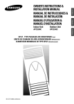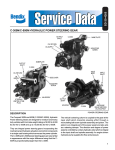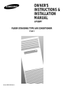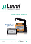
1
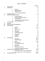
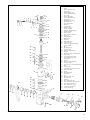
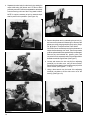
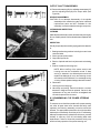
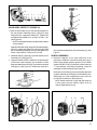
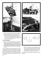
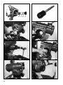
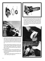
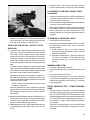
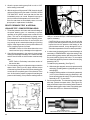
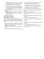
SD-30-4250 ® COMPACT 500 INTEGRAL HYDRAULIC POWER STEERING GEAR FOR FORD MOTOR CO. CARGO VEHICLES I. DESCRIPTION The Compact 500 Hydraulic Power Steering gear is designed for heavy duty vehicles with front axle weight ratings of up to 15,000 lbs. It is an integral power steering gear incorporating the mechanical and hydraulic actuation and control components in a single cast housing which serves as the power cylinder. The vehicles steering column is coupled to the gear at the input shaft which transmits steering effort through a recirculating ball screw and piston nut. The piston nut is an integral part of the power assist piston and also acts as a steering damper. The direction and degree of power assist is controlled by a rotary hydraulic valve which is integral to the input shaft and supplied by an engine driven hydraulic pump. This valve design assures light, responsive steering while maintaining a mechanical connection between the steering column and the ball screw. II. OPERATION GENERAL The C-500 integral power steering gear is composed both of mechanical steering components and hydraulic power assist components. Actual steering is accomplished mechanically. Effort applied at the vehicles steering wheel results in mechanical movement within the steering gear which causes the vehicle to change its direction of travel. The hydraulic power assist components function solely to reduce the effort required to turn the vehicles steering wheel. Loss of hydraulic power will in no way prevent the vehicle from being maneuvered mechanically, however greater effort will be required to turn the steering wheel. MECHANICAL OPERATION The turning effort exerted by the driver on the steering wheel is transmitted to the input shaft which is part of the ball screw assembly. The ball screw and piston nut function like 1 TABLE OF CONTENTS I. II. III. IV. V. VI. VII. VIII. IX. X. XI. 2 DESCRIPTION OPERATION 1. General 2. Mechanical Parts 3. Hydraulic Parts 4. Power Steering Identification TECHNICAL DATA PREVENTIVE MAINTENANCE 1. Power Steering Oil 2. Draining and Filling the System 3. Change Intervals 4. Output Shaft Sector Teeth Adjustment 5. Output Shaft Boot Seal CAUTION NOTE REMOVAL SPECIAL TOOL REQUIREMENTS DISASSEMBLY 1. General 2. Piston 3. Main housing 4. Side cover 5. Valve Body 6. Pressure Relief Valve 7. Output shaft 8. Cleaning 9. Inspection REASSEMBLY 1. Valve body 2. Spindle assembly 3. Piston 4. Main housing 5. Housing and valve body 6. Output shaft 7. Side cover 8. Housing and side cover 9. Adjustment of output shaft backlash PRESSURE, FLOW & LEAKAGE TESTS 1. Relief Pressure Test - Power Steering Pump 2. Relief Pressure Test - Power Steering Gear TROUBLESHOOTING Page No. 2 2-4 2 2 2, 3 4 4 4-5 4 4 5 5 5 5 6 6-7 9-16 9-11 11-13 13 13 14 15 16 16 16 16-23 16-17 17-18 19-20 21 21 21 22 23 23 23-25 24 24-25 25-27 LEFT TURN RIGHT TURN STEERING WHEEL BALL SCREW PISTON NUT PISTON NUT SPINDLE RECIRCULATING BALLS RECIRCULATING BALLS PITMAN ARM POWER CYLINDER PITMAN ARM FIGURE 1 - MECHANICAL OPERATION a screw and nut through the action of the chain of recirculating balls that serve as an interface. Rotation of the ball screw causes axial movement of the piston within the power cylinder. Gear teeth cut directly into the piston mesh with corresponding sector gear teeth on the output shaft and as the piston moves, the output shaft and attached pitman arm are rotated. HYDRAULIC OPERATION The driven end of the ball screw rotates on a ball bearing contained in the valve body. Hydraulic pressure enters and exits the power steering gear through lines connected to threaded ports in the valve body. A pressure relief valve contained in the valve body prevents overpressurization of the power steering gear. Hydraulic pressure in excess of the setting of the relief valve causes the valve to open a channel to the reservoir return side of the gear. The ball screw assembly is retained in the valve housing by a valve nut which forms the outermost element of the rotary control valve. The valve nut contains circular channels and radial passages which serve to direct hydraulic oil into and out of the rotary control valve. The ball screw assembly forms the rotary control and consists of three parts; the input shaft, torsion bar, and ball screw. One end of the input shaft is finely splined for connection to the steering column while the other end has a coarse spline which fits loosely with a similar spline inside the worm screw. The coarse splines form mechanical stops which limit the amount of relative rotation between the ball screw and input shaft. A torsion bar connects the input shaft to the ball screw. Six evenly distributed longitudinal grooves are machined into the outer surface of the input shaft and correspond to six grooves machined into the bore of the ball screw. Holes extend from the outside surface of the ball screw into the six grooves in the bore. These holes allow pressurized oil to enter and exit the two inner elements of the rotary control valve. The six grooves in the bore of the ball screw are connected alternately to each side of the piston through three pairs of the drilled holes. The other three holes admit pressurized oil directly to three of the six grooves in the input shaft. The other three grooves in the output shaft carry oil to the return line connection. The length of the six pairs of grooves cut into the ball screw and input shaft allows large pressure changes to be achieved with a small rotational displacement of the valve elements. The rotary control valve is an open center type which allows a continuous flow of oil (through the longitudinal grooves in the input shaft and bore of the ball screw) when held in the neutral position by the torsion bar. The large porting of the valve design allows neutral position operating pressure to remain in the 40-65 psi range which results in reduced hydraulic pump power consumption and lower oil temperatures. When steering effort is applied, the input shaft and ball screw tend to turn in unison however the spring action of the torsion 3 CIRCULAR GROOVES BY PASS VALVE OIL IN ROTARY VALVE SUPPLY OUTPUT SHAFT INPUT SHAFT VALVE NUT OIL OUT DELIVERY FROM ROTARY VALVE SPINDLE ASSEMBLY W/ ROTARY VALVE (BALL SCREW ASSEMBLY) PISTON SEAL AND GLIDE RINGS OIL PASSAGE DRAIN PLUG FIGURE 2 bar results in the input shaft rotating slightly in advance of the ball screw. The six pairs of grooves that form the rotary control valve are displaced from their neutral flow position. As steering effort increases so does the amount of displacement. Depending on the direction steered, the groove displacement of the input shaft directs hydraulic oil through BY PASS VALVE OIL INLET CONNECTING POLE the appropriate drilled passages in the ball screw to one side or the other of the piston. Hydraulic pressure acting upon the piston surface eliminates much of the pistons resistance to movement. Spring force exerted by the torsion bar causes the ball screw to rotate as piston resistance is removed. As the ball screw rotates, the relative groove INPUT SHAFT BEARING OIL OUTLET CIRCULAR GROOVES LONGITUDINAL GROOVES MECHANICAL MOVEMENT PARTS MECHANICALHYDRAULIC PARTS PARTS WITH NO MOVEMENT FIGURE 3 4 TORSION BAR BALL SCREW RETURN BY-PASS VALVE PUMP LEFT TURN STRAIGHT AHEAD RIGHT TURN FIGURE 4 - SCHEMATIC OF THE ROTARY VALVE OPERATION displacement is eliminated and the rotary valve returns to a neutral position. Moderate effort at the steering wheel produces smaller valve displacements and lower power assist, thus providing good steering feel. At increased displacements the pressure rises more rapidly giving increased power assistance and quicker response. Maximum pressure is developed after approximately 3' displacement giving a direct feel to the steering. Groove displacement is limited by the freeplay of the stop spline mesh between the input shaft and ball screw. The splines take up the steering movement while allowing the torsion bar to hold the groove displacement. The torsion bar and stop splines form two parallel means of transmitting the steering torque. When no steering torque is applied, the torsion bar returns the valve grooves to a neutral position allowing the pressurized oil to flow to the return line. Power assisted movement of the piston nut within its bore is limited by poppet valves installed in both piston faces. When the piston approaches its extreme travel in either direction, the stem of the limiting poppet valve makes contact at the end of the piston bore. As piston travel continues, the limiting poppet is unseated and some hydraulic power assist is removed as pressurized oil is diverted to the return line. As more and more power assist is removed by the action of the limiting poppet valves, steering effort increases. The piston can travel to the extreme ends of its bore, however, the maximum steering assistance available is reduced to protect the steering components in the axle. in operation. Oil displaced from one side of the piston is essentially transferred to the other side which prevents reservoir flooding and cavitation in the pressure line. The pressure relief valve is located in the valve body and limits internal hydraulic pressure to a preset maximum. The pressure relief valve can be set to various pressures, however its setting is 150 p.s.i. lower than the power steering pump relief valve setting. POWER STEERING GEAR IDENTIFICATION A nameplate is installed adjacent to one of the mounting lugs of the unit which indicates part number, serial number and build date. III. TECHNICAL DATA - Steering ratio ........................................................... 21:1 - Number of turns of the steering wheel ..................... 5.25 - Turning angle on the output shaft ....................... 90° + 2° - Output shaft torque obtained with an effective pressure of 1885 p.s.i. (132.5Kg/cm2) .......... 41,947 in.-Ibs (474 m/Kg) - Hydraulic oil ............................................... Ford part no. (Ford Esp. M2C1 38-CJ) XT-2-QDX (Dextron II) - Normal working temperature .................... 248°F(120°C) - Normal peak temperature ........................ 302°F (150°C) - Normal flow ......................... 4.2 + 2 G.P.M. (16 + 1 L/m) - Maximum working pressure 1885 + 60 psi(130+4Kg/cm2) - Maximum pressure drop in the return ducting ................. ............................................................. 60 psi (3 Kg/cm2) The bypass valve is located in the valve body and permits oil to flow from one side of the piston to the other when it is necessary to steer the vehicle without the hydraulic pump 5 IV. PREVENTIVE MAINTENANCE POWER STEERING OIL It is important that an approved oil be used to assure proper operation of the power steering unit. The vehicle manufacturers recommendations should be adhered to. Once an oil type is in use, it should never be mixed with any other type. If it should become necessary to change types of oil, the entire system must be drained following the procedure below. DRAINING AND FILLING THE SYSTEM 1. Lift the front axle sufficiently to raise the wheels clear of the ground. 2. Disconnect the return line at the valve body outlet port. The outlet port is identified by the arrow which flows out of the gear. Turn the steering wheel to the left as far as it will go. Run the engine for 10 seconds at the most until the oil is drained from the reservoir and pump. Switch off the engine and turn the steering wheel backwards and forwards from full lock to full lock until all the oil is drained out. 3. Clean the outside of the reservoir. Remove the old filter element. Oil the filter support and assemble with a new filter. 4. Fill reservoir full of oil. 5. Turn the engine over with the starter motor. (Must be done in a manner that the engine does not start.) Add oil as the level drops to avoid air being drawn into the system. RECIRCULATING BALLS ROTARY VALVE GLIDE RING (3) VALVE NUT SPINDLE (BALL SCREW) LIMITING POPPET HOUSING INPUT SHAFT PISTON VALVE STOP SEAL & GLIDE RINGS OUTPUT SHAFT SECTOR GEAR BALL BEARING PITMAN ARM NUT TORSION BAR FIGURE 5 6 NEEDLE BEARING O-RING (3) BOOT OUTPUT SHAFT 297676 297661 297674 FIGURE 6 - REQUIRED TOOLS 6. When the oil level reaches the full mark on the dipstick, start the engine and turn the steering wheel slowly from side to side until air bubbles cease to appear in the reservoir. Refill reservoir to full mark on the dipstick. 7. The oil level should be checked every 2,000 miles. The correct level is between the minimum and maximum level marks on the dipstick with the engine stopped. CHANGE INTERVALS It is recommended that the oil be changed at 40,000 mile intervals and at the time of rebuild. Beyond its function as the media for transmitting power, the oil also serves to lubricate and dissipate heat. Carefully clean, inspect, and replace if necessary all filter elements in the pump system including vents and breathers. OUTPUT SHAFT SECTOR TEETH ADJUSTMENT The gear lash between the piston teeth and sector gear should not require attention in normal service, however a provision for adjustment is provided. Adjustment requires that the steering gear be drained and the pitman arm and input shaft disconnected from the vehicle. The adjustment procedure is described at the end of the assembly section of this manual. OUTPUT SHAFT BOOT SEAL Inspect the integrity of the output shaft boot seal located between the pitman arm and housing. This component prevents contamination from entering the output shaft bearing and retains grease on the bearing and output shaft to prevent corrosion. If deterioration or leakage is detected, it should be replaced. 297675 297660 V. IMPORTANT! PLEASE READ: When working on or around the Power Steering system and components, the following precautions, should be observed: 1. Always block vehicle wheels. Stop engine when working under a vehicle. Keep hands away from pinch points. 2. Never connect or disconnect a hose or line containing pressure. Never remove a component or pipe plug unless you are certain all system pressure has been depleted. 3. Never exceed recommended pressure and always wear safety glasses. 4. Never attempt to disassemble a component until you have read and understood recommended procedures. Use only the proper tools and observe all precautions pertaining to use of those tools. 5. Use only genuine Bendix replacement parts and components. A. Only components, devices and mounting and attaching hardware specifically designed for use in hydraulic systems should be used. B. Replacement hardware, tubing, hose, fittings, etc. should be of equivalent size, type and strength as the original equipment. 6. Devices with stripped threads or damaged parts should be replaced. Repairs requiring machining should not be attempted. VI. REMOVING THE POWER STEERING GEAR 1. Mark or identify the inlet and return lines at the valve body ports. 2. Drain the system following the instructions presented under preventive maintenance. Remove both inlet and return lines. 7 3. Disconnect the steering column at the input shaft following the vehicle manufacturers instructions. 297678 Holding Fixture - Used to hold the piston and the valve assembly during disassembly and assembly. Note: Part No. 297678 includes the holding fixture and spanner wrench 297661. 4. Disconnect the pitman arm from the vehicles steering linkage using the vehicle manufacturers instructions. CAUTION: If it is necessary to remove the pitman before the steering gear can be removed from the vehicle, DO NOT USE HEAT OR POUND ON THE PITMAN ARM OR OUTPUT SHAFT as damage can result. Do not attempt repairs to these components. They must be replaced if damaged. Use a large gear puller to remove the pitman arm such as Snap-On puller #CG-283 or Ford part number T64P-3590-F. 5. Remove the steering gear from the vehicle. VII. SPECIAL TOOL REQUIREMENTS The following special tools are required to disassemble and assemble the power steering gear. 297661 Spanner Wrench - Used to remove and replace the valve nut. 297676 Seating Tool - Used to assure seating and prevent damage to the teflon glide seal rings in the valve nut during reassembly. 297674 Piloted Seal Tool - Used to seat the seal and spacer in the body of the power steering gear. 297675 Piloted Seal Tool - Used to seat the seal in the end cover. 297660 Poppet Wrench - Used to remove and install limiting valve poppets. The following special tools are available and are useful but not required for routine disassembly/assembly of the power steering gear unless replacement of the bearing races is required. 297677 Piloted Bushing Tool - Used to seat the bearing race in the main housing. 297647 Piloted Bushing Tool - Used to drive bearing race out of the main housing. Also used to drive split bearing race into valve body. VIII. DISASSEMBLY GENERAL A high level of cleanliness should be observed at all times when working on the power steering gear. Clean the exterior of all parts prior to disassembly. The following disassembly and assembly procedure is presented for reference purposes and presupposes that a major rebuild of the power steering gear is being undertaken. Several replacement parts and maintenance kits are available which do not require full disassembly. The instructions provided with these parts and kits should be followed in lieu of the instructions presented here. OUTPUT SHAFT REMOVAL 1. After removing the power steering unit from the vehicle and cleaning the outside, secure the power steering unit to the work bench for disassembly. A large vise with jaw protectors may be used. Clamp across the mounting bolt bosses. (Do not overtighten.) 2. Using a 17mm wrench, remove the drain plug from the housing and drain out all oil. (Fig. 8) 3. Loosen and remove the four bolts(1) from the valve body with a 22mm socket. (See Figures 7 & 9) 297678 297677 FIGURE 6A - NON REQUIRED TOOLS 8 297647 6 3 4 7 8 5 9 1 13 14 2 15 1. 2. 3. 4. 5. 6. 7. 8. 9. 10. 11. 12. 13. 14. 15. 16. 17. 18. 19. 20. 21. 22. 23. 24. 25. 26. 27. 28. 16 17 18 10 11 12 19 28 29 30 28 34 52 29. 30. 31. 32. 33. 34. 35. 36. 37. 53 54 29 31 32 56 32 57 31 31 38. 39. 40. 41. 32 33 29 48 22 50 56 29 49 55 47 53 46 51 46 52 45 42. 43. 44. 45. 46. 47. 48. 49. 50. 51. 52. 53. 54. 55. 56. 57. Valve Body Bolt Washer Pressure Relief Valve Plug Sealing Washer Adjusting Washer (Shim) Pressure Relief Valve Spring Spring Guide Pressure Relief Valve Pressure Relief Valve Seat Sealing Washer By-pass Ball Valve Spring By-pass Ball Valve Input Shaft Dust Seal Snap Ring Input Shaft Seal Valve Body Housing Valve Body O-Ring Valve Body Seal Ring (Nylon) Valve Body O-Ring Pitman Arm Nut Pitman Arm Nut Lock Washer Pitman Arm Output Shaft Boot Boot Retainer Snap Ring Needle Bearing Assy Output Shaft Seal Valve Body & Spindle Ball Bearing Outer Race (Split) Ball Ball Bearing Cage Valve Nut O-Ring Valve Nut Teflon Glide Ring Valve Nut Spindle Assy. (Valve & Ball Screw Assy.) Output Shaft Output Shaft Adjusting Screw Output Shaft Adjusting Screw Shim (Washer) Snap Ring Side Cover Output Shaft Seal Side Cover O-Ring Side Cover Assy. (includes Needle Bearing Assy.) Side Cover Bolt Output Shaft Adjusting Screw Lock Nut Housing Drain Plug Housing Piston Backup Ring Piston O-Ring Piston Recirculating Ball Tube Ball Tube Cover Snap Ring Piston Limiting Body Nut Piston Limiting Body and Valve Seat Piston Limiting Stem (Short) Piston Limiting Stem (Long) Limiting Body Stop Washer Limiting Valve Spring 20 21 23 35 24 25 26 36 39 2 27 44 4 42 37 38 40 43 41 FIGURE 7 9 4. Separate the valve body from the housing by rotating the output shaft using the pitman arm if it has not been previously removed. Continue to separate the valve body from the housing until one of the O-ring seals is visible. NOTE: It may be necessary to hold or rotate the input shaft to perform this operation. (See Figure 10) FIGURE 10 5. Remove the pitman arm by unbending the nut lock (21) and remove the pitman arm fastening nut. Remove the pitman arm using a large gear puller such as the SnapOn #CG-283 or Ford part number T64P-3590-F. FIGURE 8 CAUTION: Do not use heat or pound on the pitman arm or output shaft as damage can result. These components must be replaced rather than repaired if they are damaged. Remove any accumulated dirt, grease, grime, and corrosion from the exposed portion of the output shaft to facilitate removal through its seal. (See Figure 7) 6. Loosen and remove the lock nut(43) from adjusting screw(36) on the side cover, using a 24mm socket. Remove the four bolts(42) from the side cover(41) with a 22mm socket. (See Figures 7, 11 & 12) 7. Using a 9mm wrench turn the head of the adjusting screw(36) clockwise to lift the side cover out of the housing. (See Figure 13) FIGURE 9 10 FIGURE 11 41 36 2 43 42 FIGURE 14 FIGURE 12 8. Install the pitman arm and use it to center the piston and output shaft sector teeth inside cover opening. Remove the pitman arm and then remove the output shaft by tapping gently on the splined end with a nylon mallet. (See Figures 14 & 15) FIGURE 13 FIGURE 15 11 FIGURE 18 FIGURE 16 PISTON REMOVAL & DISASSEMBLY 9. While preventing rotation of the input shaft, remove the spindle, valve body and piston from the housing. (See Figure 16) Remove the two O-rings(19) from the valve body. (See Figure 17) Remove the O-ring(47) and two back-up rings(46) from the piston groove. (See Figure 18) Remove the snap ring (51) and tube cover(50) and lift out and remove both halves of the ball return tube(49) (7 balls inside). (See Figure 19) 51 49 50 29 TOOL 297678 FIGURE 17 12 46 47 FIGURE 19 45 27 25 26 24 23 FIGURE 23 FIGURE 20 Rotate the input shaft and spindle(34) counterclockwise to remove the remainder of the 26 internal balls(29) (a small magnet is a useful tool for this operation.) Separate the piston from the spindle. (See Figure 21). Holding fixture 297678 pictured is a convenience but not a necessity to disassemble and assemble the steering gear. IMPORTANT: Though being of the same size, recirculating balls, bearing balls and limiting valve balls must not be mixed or replaced with each other. 10. Mark or otherwise identify the limiting valve stems (54 & 55) with regard to which end of the piston(48) each is located. IMPORTANT: These stems must be installed in the same end of the piston from which they are removed. (See Figure 7) 11. Using the 6mm hollow hex wrench, tool #297660 (See Figure 6), installation on the valve stem(54) until the hex of the wrench engages the hex of the limiting body nut(52). 12. Using a 6mm socket to turn the hex wrench, remove the nut(52), body(53), stem(54), ball valve(29), stop washer(56), and spring(57). The ball valve(29) and stem(55) may also be removed. FIGURE 21 13. Remove the limiting body nut(52) limiting body(53) and stop washer(56) from the other end of the piston(48). HOUSING DISASSEMBLY 14. Remove the rubber boot(23) and boot retainer(24) from the main housing(45). (See Figure 22) Take out the snap ring(25) and extract bearing assy.(26) and seal(27). (See Figure 23) NOTE: Do not remove the outer bearing race if in good condition. If it is necessary to remove the outer bearing race, use tool 297647 and drive the race into the housing(45) until it is free. FIGURE 22 13 41 40 39 FIGURE 24 SIDE COVER DISASSEMBLY 15. Remove O-ring(40) and seal(39). (See Figure 24) NOTE: Do not attempt to remove the bearing. The side cover MUST BE replaced if it is determined that the bearing requires replacement. The side cover is supplied with the bearing factory installed. VALVE BODY AND SPINDLE DISASSEMBLY 16. With a drift punch unblock the safety point between valve nut(33) and valve body(16). Loosen and remove the valve nut with spanner wrench 297661 and remove the spindle assembly(34), the ball race(28), the ball cage(30), and the seventeen bearing balls. (See Figure 25) 33 28 34 30 29 17 16 TOOL 297678 FIGURE 25 14 14 16 15 16 11 12 10 9 8 7 6 5 4 3 FIGURE 26 17. Remove the inner O-ring(17) and the nylon seal ring(18) from the valve body(16). NOTE: Do not remove the inner ball race(28) from the valve body(16) if it is in good condition. 18. Then remove the dust seal(13), snap ring(14) and the seal(15) from the valve body(16). (See Figures 7 & 26) PRESSURE RELIEF BYPASS VALVE DISASSEMBLY 19. The power steering valve body(16) contains a pressure relief and safety valve. Loosen and remove the plug(3) with a 26mm wrench and the corresponding seal washer(4). FIGURE 27 CAUTION: Located in the plug are the corresponding maximum pressure adjusting shims(5). (See Figure 27 & 28) Proper reinstallation of the shims is critical to maintain correct relief pressure. Remove the spring(6), the guide(7) and the valve(8). With a wide blade screwdriver loosen and remove the valve seat(9) and its copper seal washer(10) as well as the spring(11) and the ball(12) of the bypass valve. NOTE: Be careful not to damage the I.D. of the valve body or the valve seat(9) with the screwdriver. 15 OUTPUT SHAFT DISASSEMBLY 20. Remove the snap ring(38), the adjusting screw spacer(37) and the adjusting screw(36) from output shaft. (See Figure 29) 3 4 5 6 7 8 10 11 12 9 SPINDLE DISASSEMBLY CAUTION: Do not attempt disassembly of the spindle assembly which contains the rotary valve. Individual replacement parts are NOT available for this assembly. It must be treated as a single component. CLEANING AND INSPECTION CLEANING Wash all parts individually in clean solvent and dry thoroughly. All non-metallic parts should be discarded and replaced with new. INSPECTION Visually inspect all parts carefully paying particular attention to: 1. Bearings and bearing surfaces including inner and outer races and balls. 2. Sector gear and piston teeth. 3. Output and input shaft. FIGURE 28 4. Exterior of spindle and interior of piston and recirculating balls. 5. Exterior of piston and housing bore. 36 35 37 38 NOTE: Minor scuffing of the piston exterior and housing bore can be considered normal. If deep scoring is detected, the affected parts should be replaced as leakage will occur and steering control and reaction will be affected. Do not attempt honing or boring of these parts as leakage rates will increase. 6. Pitman arm. 7. Housing and mounting lugs. 8. Valve body and porting. Parts found broken, cracked, distorted or fatigued must be replaced. Cause for the replacement of any part should be investigated and corrected to prevent reoccurrence. IX. REASSEMBLING THE POWER STEERING UNIT To ensure a correct fault-free operation of the power steering unit, after all parts have been cleaned and faulty ones replaced, the following assembly procedure should be followed. The appropriate maintenance kit or kits should be obtained prior to assembly. Should any of the 17 ball bearing balls require replacement, replace them all at once; proceed similarly in case any of the 26 recirculating balls need replacement. Failure to follow this procedure strictly may result in a faulty operation of the power steering unit. FIGURE 29 16 33 16 12 10 9 11 4 8 7 6 5 3 28 34 30 FIGURE 30 VALVE BODY (REFER TO FIGURE 30) 29 1. Place the valve body(16) in a vise and lightly tighten on the cast surface. Install the ball(12), spring(11) valve seat(9) and the copper/seal washer(10). Tighten with an appropriate screwdriver to a torque of 200 in. lbs. (See Figure 30) NOTE: A new copper washer(4) must be used to assure correct sealing. Install the relief valve rod(8), the guide(7) and the spring(6). Place the copper seal washer(4) onto the plug(3) with the corresponding adjusting shims(5) and tighten with 26 mm. torque wrench. Torque to 66-74 ft. lbs. 2. Install the seal(15), snap ring(14), and dust seal(13) into valve body(16). (See Figure 31) 3. Using tool number 297647, install the inner ball race(28) (in the event it was removed), into the bottom of valve body and install internal O-Ring(17) and the two external O-Rings(19). (See Figure 32). Install nylon seal(18) in 16 FIGURE 33 the internal threaded portion of the valve body(16). (See Figure 7) SPINDLE ASSEMBLY 4. Install the cage(30) on the input shaft end of the spindle(34). Install the outer ball race(28) and using a lithium base general purpose grease (Ford Chassis grease ESA-M1C75-B) to hold them in place insert the 17 new balls(29) comprising the bearing. Insert the assembly into the valve body. (See Figure 33) Remove from the valve nut(33), the three teflon glide seal rings(32) and the three O-Rings(31) and install new ones. When they are in their respective grooves, insert the tool 297676 to seat them. (See Figure 34) 13 14 15 16 NOTE: Make certain the O-rings and glide rings are in their proper grooves. (Refer to Figure 5) An oil channel separates each ring. FIGURE 31 16 19 28 33 17 31 32 297676 18 FIGURE 32 FIGURE 34 17 34 51 46 50 297676 29 33 49 16 47 FIGURE 35 FIGURE 36 Without removing tool 297676, insert the nut(33) into the valve body(16), screw and tighten it to a torque of 330 ft. lbs. with a spanner wrench. (See Figure 35) NOTE: Tool 297676 for the teflon glide rings will come out as the nut is screwed into the valve body. Lock the nut in the valve body by staking the edge of the valve nut into the valve body. PISTON ASSEMBLY 5. Refer to Figure 37. Install stop washer (56), limiting valve stem(54), limiting body(53), in the appropriate end of the piston(48). Apply a small amount of LOCTITE 222 on the threads of the limiting body nut(52) and install the nut in the piston. Torque the nut to 17 foot pounds using the 6mm hollow hex wrench (Tool 297660) and a 6 mm socket. From the opposite end of the piston install one of the two ball valves (29), the spring (57), ball valve (29), stop washer (56), limiting valve stem (55), limiting body (53). Apply a small amount of locktite 222 on the threads of the limiting body nut (52) and install the nut in the piston. Torque the nut 17 foot pounds using the 6mm hollow hex wrench and a 6mm socket. 18 52 55 57 56 56 52 54 48 53 29 29 53 FIGURE 37 NOTE: The limiting valve stems (54&55) must be installed in the same end of the piston as they were removed. Reference Disassembly, Step 10. When installing new stems (54&55), the shorter stem must be installed facing the valve body housing side. Install the ball screw by inserting it into the piston (48). (See Figure 36) Insert the 19 balls (29) one by one in one of the openings for the recirculating tubes located in the piston (48) while turning the spindle at the same time. Balls inserted in one opening should recirculate to the opposite opening as the ball screw is rotated. Before proceeding, make certain the balls are at an equal depth in both holes of the piston. (See Figure 38). This will assure correct installation of the return tube (49). Install the seven remaining balls(29) into the ball return tube halves(49) using lithium base general purpose grease (Ford Chassis grease ESA-M1C75-B) to retain the balls. Place the tube into piston(48), install the tube cover(50) and its snap ring(51). Check for smooth operation of the spindle assembly. (See Figure 39) NOTE: the utmost care must be taken with these steps. Incorrect assembly of this group may result in one or more balls failing inside the piston or coming out at the top of it and lodging in the bottom of the housing(45). FIGURE 39 Install the O-Ring(47) and back-up rings(46) on the piston. (See Figures 36 & 40) FIGURE 40 NOTE: Make certain to rotate the glide rings(46) so that their gaps are 180° apart and not in line with each other. HOUSING ASSEMBLY FIGURE 38 6. If the outer race of bearing(26) was removed, it must be reinstalled using tool 297677. Center the narrow bearing spacer on tool 297677 then install the bearing(26) complete with its outer race(26) on the tool. Drive the bearing and race along with the spacer into the housing from the output shaft side of the housing until the tool bottoms against the outside of the housing. (See Figures 41A, B & C) Remove the tool and check to be certain that the outer race and spacer have been driven into the housing sufficiently deep to allow installation of the snap ring(25). If the snap ring(25) cannot be installed, remove the narrow bearing spacer and using tool 297647 drive the bearing race further into the housing. Reinstall the narrow bearing spacer and install the snap ring(25), making certain it is completely seated in its groove. Using tool 297647 tap the outer race from inside the housing 19 27 26 FIGURE 41 20 25 24 23 until the bearing spacer and outer race are seated against the snap ring. Install the seal(27) on tool 297674 so that the seals lip groove rests against the large diameter of the tool. Next install the thick bearing spacer on the tool making certain the flat side of the bearing spacer rests against the seal. (See Figures 41 E, F & G) Insert the tool with the parts installed on it through the side cover opening and using a mallet drive the seal into place. Install the boot retainer(24) in the housing. Next install the small diameter of the boot(23) into the retainer, making certain it is fully seated within the groove formed by the retainer. 8. Install into the output shaft(35), the adjusting screw(36), the adjusting screw spacer(37) and the snap ring(38). Spacer(37) thickness is to be selected so that the axial play of the adjusting screw is between 0 and .0025 inch after the snap ring is installed. (See Figure 44) NOTE: After selecting the proper spacer(37) thickness, disassemble it, grease the screw head with a lithium base general purpose grease (Ford chassis grease ESA-M1C75-B), and reassemble screw, spacer, and snap ring. HOUSING & VALVE BODY ASSEMBLY 7. Insert the valve body, spindle and piston assembly into the housing making certain not to damage the O-ring seals. Install the 4 bolts(1) and washers(2) that secure the valve body to the housing and tighten to a torque of 96 ft.lbs. with a 22mm torque wrench. Turn the input shaft to center the piston teeth(48) in the side cover opening. This will facilitate the installation of the output shaft and allow the proper mesh between the sector and piston teeth. (See Figure 43) 1 PISTON OUTPUT SHAFT FIGURE 43 2 16 ADJUSTING SCREW WASHER FIGURE 42 FIGURE 44 21 41 40 39 36 35 41 FIGURE 46 Prior to inserting the output shaft into the housing, wrap a single layer of masking tape around the splines and threads to protect the housing seal. Lubricate the exterior of the tape with a lithium base grease (Ford Chassis grease ESA-M1C75-B) and insert the shaft and side cover assembly into the housing with a twisting motion. (See Figure 47) FIGURE 45 9. Install the side cover seal(39) on tool 297675 so that the seals lip groove rests against the large diameter of the tool. Insert the tool with the seal installed into the side cover and using a mallet drive the seal into place. Install the o-ring(40) in its groove on the side cover. (See Figure 45) Pack the output shaft roller bearings in the side cover and housing with a general purpose lithium base grease (Ford Chassis grease ESA-M1C75-B). Lubricate the seals in the side cover and housing using a portion of the same grease. 10. Install the side cover(41) onto the output shaft(35). Turn the adjusting screw(36) counterclockwise with a 9mm socket until finger tight, then back off an eighth of a turn. (See Figure 46) NOTE: Be sure output shaft has contacted side cover prior to backing off an eighth turn. FIGURE 47 22 14. Install the gear on the vehicle and test for flow and pressure values shown in Section III of Technical Data. X. PRESSURE, FLOW AND LEAKAGE TESTS PRELIMINARY 1. Connect Rotunda analyzer kit 14-0230 or equivalent to the power steering system as shown in Figure 49. Be sure shutoff valve is fully open. 2. Put front wheels in straight ahead position, transmission in neutral, parking brake engaged. FIGURE 48 Install the four washers(2) and the four bolts(42) that secure the side cover to the housing and torque to 96 ft.lbs. with a 22mm wrench. (See Figure 48) ADJUSTING THE PISTON - SECTOR TOOTH BACKLASH 11. The piston and output shaft gear backlash is correct when a 4 to 18 inch pound increase in torque is noted as the input shaft is rotated and the piston passes through the mid point of its total travel in the housing. The torque increase on the input shaft will occur only as the piston travels through the mid point of its travel and should disappear as the piston moves past the mid point. To obtain the above adjustment, rotate the input shaft 180° in both directions past the mid point of piston travel. (The mid point of piston travel is approximately one half the number of input shaft revolutions possible.) Each time the direction of input rotation is changed, turn the output shaft adjustment screw(36) clockwise 1/8 to 1/4 turn. Continue this procedure until the 4-18 inch pound increase in torque is noted. NOTE: A 19mm 12 point socket wrench can be used to rotate the input shaft. When the adjustment is correct, install lock nut(43) and apply a torque of 103 ft. lbs with a 24mm torque wrench while holding the adjusting screw in position with the 9mm socket. 3. Start engine and partially close the pressure line shutoff valve until 800-1000 p.s.i. is read at the pressure gauge. When temperature of power steering fluid in the reservoir reaches 120°F, fully open shutoff valve and turn engine off. SYSTEM BACK PRESSURE CHECK 1. Insure shut off valve is fully open. 2. Start engine and increase speed to 2200 r.p.m. When fluid temperature reaches 130°F (55°C), record flow rate and pressure. A. If flow is below 3.5 g.p.m. (13.2 L/min.). Check to see if correct pump is installed. If correct, continue testing to find problem. B. If pressure exceeds 80 p.s.i. (552 kPa), check lines for kinks or obstructions. If none are found and pressure remains high, continue testing to find problem. MINIMUM PUMP FLOW 1. Decrease engine speed to 600 rpm. 2. Slowly close shutoff valve to increase pressure to 1200 p.s.i. 3. Record flow rate at 130°F (55°C). 4. If flow rate is below 2.2 g.p.m. (8.3 L/min), then verify correct pump is installed. Pump may require repair or replacement especially if flow at 2200 r.p.m. was also below specification. RELIEF PRESSURE TEST - POWER STEERING PUMP 12. After all the described steps have been performed, check that the power steering unit runs smoothly throughout its entire motion and that the backlash at the center position is as prescribed in Step 11 above. 1. With the engine running at 600 r.p.m. close the shutoff valve and read the pressure gauge and note the flow rate is 0. OPEN THE SHUTOFF VALVE QUICKLY after reading the gauge pressure and note the flow rate returns to normal. If the pressure reading is below 1800 p.s.i. or above 2250 p.s.i., repair or replacement of the relief valve is necessary. 13. Install the pitman arm(22) on the output shaft and secure it using washer(21) and nut(20). Torque nut to 370-410 ft. lbs. CAUTION: The shutoff valve must not remain closed longer than FIVE SECONDS or damage to the pump may result. 23 2. Allow the power steering pump fluid to cool to 130°F before testing is resumed. 3. With the engine at full governed R.P.M. close the shutoff valve and note that the flow reads 0. QUICKLY OPEN THE SHUTOFF VALVE, and note that the flow rate immediately returns to normal. Repeat this test once but do not allow fluid temperature to exceed 200°F. AXLE STOP If the flow rate does not immediately return to normal, pump repair or replacement is indicated. RELIEF PRESSURE TEST & INTERNAL LEAKAGE TEST - POWER STEERING GEAR 1. To test the pressure relief valve and internal leakage of the power steering gear, it is necessary to prevent operation of the gears poppet valves contained in the piston. This can be accomplished by placing a steel block between the axle stop and the adjusting screw. The block should be a minimum of one inch thick and long enough to be inserted without danger of pinching fingers. Keep fingers clear of pinch points and be sure block is square to points of contact. WARNING: Failure to follow these instructions can result in serious injury or damage to the equipment. 2. Check fluid temperature in the reservoir, thermometer reading should be approximately 130° at start of the test and the shut off valve on the flow meter must be totally open. NOTE: Refer to Preliminary Instructions section of the service data. 3. Turn the steering wheel until the axle stops contact the spacer block. (See Figure 50) Apply sufficient torque to the steering wheel to assure the power steering gear control valve is completely open in the direction of the turn. At this time the pressure gauge will read the gear pressure relief setting. If the pressure reading is above THERMOMETER POWER STEERING GEAR FIGURE 50 1945 p.s.i. or below 1825 p.s.i. relief valve adjustment or repair is necessary. CAUTION: When running this test, do not hold the torque on the steering wheel for more than 5 seconds beyond the time the pressure relief setting of the gear has been reached. It may damage the unit or cause the temperature of the oil to raise beyond 200°. 4. In order to test the steering gear for internal leakage it is necessary to TEMPORARILY adjust the setting of the power steering gear pressure relief valve above that of the power steering pump relief valve. To accomplish this install the appendix pressure relief valve test plug assembly 106773. To install the plug assembly: (See Figure 7) A. With the engine stopped, remove the pressure relief valve plug (3) sealing washer (4) adjusting shims (5) and spring(6). B. Install the sealing washer on the test plug assembly (106773) then install the test plug assembly in the power steering gear valve body. Torque the test plug assembly to 66 - 73 pound feet. 5. Run the engine at idle. Turn the steering wheel until the axle stop contacts the spacer block. (See Figure 50) Apply a sufficient torque to the steering wheel to assure the power steering gear control valve is completely open in the direction of the turn. Observe the following. OIL RESERVOIR GAUGE POWER STEERING PUMP FIGURE 49 24 FLOW METER SHUTOFF VALVE PART NUMBER 106773 PRESSURE RELIEF VALVE TEST PLUG ASSEMBLY A. Gauge pressure should read the same as the power steering pump relief pressure. (See Step 1 under Relief Pressure Test - Power Steering Pump) B. With system pressure at pump relief, read the flow meter. If a flow greater than 3.5 quarts per minute is noted, internal leakage is excessive and the steering gear requires repair. 4. Visually inspect the following components for obvious damage, misadjustment and possible binding. a. steering column and universals or couplings. b. steering arms, tie rods, tie rod ends and knuckles. c. general looseness in the steering linkages. 5. Check hoses for sharp bends, kinks and proper size. 6. Repeat Test 5 turning the steering wheel in the opposite direction. The most common faults may be grouped under the following headings: IMPORTANT: Remove the pressure relief valve test plug assembly which was in Step 4, before placing the vehicle in service. 2. The power steering is still in one direction and normal in the other. 1. Power steering does not operate. XI. TROUBLESHOOTING 3. The power steering tends to turn itself when the engine is started. PRELIMINARY CHECKS 4. Excessive free play at the steering wheel. Before proceeding to the troubleshooting headings, it is strongly recommended that some preliminary checks be made and a test ride be taken to eliminate unnecessary work. 5. The power steering operates normally but is intermittently hard. 1. Check for proper and equal tire inflation on the steering axle. Note any abnormal tire wear which may be attributable to front end alignment. 2. Make certain the power steering reservoir oil level is correct. 6. Oil leaks. 7. The power steering is still when turning the steering wheel quickly. 8. The power steering does not return correctly. 9. The power steering operates but with noise, turbulence or vibration. 3. Make certain the power steering pump belt is not slipping. 25 SYMPTOM 1. Power steering does not operate. TROUBLESHOOTING CHART CAUSE A. Low oil level. B. Air in system. C. The pressure pump does not supply an adequate flow or pressure. D. Obstruction in the oil reservoir outlet or inlet. E. Communication between sides of power steering piston. F. Mechanical faults in vehicle steering members, not belonging to power steering gear. G. Low pressure in front tires. H. Relief valve opens at low pressure. I. Faulty operation of the rotary valve. 2. Power steering stiff in one direction and normal in the other. A. No pressure being applied to top or bottom side of power steering piston. B. Faulty operation of the rotary valve. C. Mechanical fault in vehicle steering members not belonging to power steering units. D. Excess leakage through piston limiting valve in one direction. REMEDY A. Check oil level. B. Check that there are no leaks, bleed and top up with oil. C. Check pump performance to specification. D. Remove lines and clean. E. Change piston seal rings. F. Overhaul and test in accordance with vehicle service manual. G. Inflate tires to correct pressure. H. Disassemble and repair. I. Replace ball screw assembly. A. Check and if necessary replace seal rings (31, 32) B. Replace ball screw assembly. C. Overhaul and check in accordance with vehicle service manual. D. Disassemble and repair. 3. Power steering tends to turn by itself when engine is running. A. Rotary valve incorrectly set. A. Replace ball screw assembly. 4. Excessive free play in steering wheel. A. Power steering housing or housing support loose. B. Excessive play between output shaft sector teeth and piston. A. Retighten mounting bolts. C. Loose or worn ball studs in steering linkage. Loose or worn intermediate steering shafts. 26 B. Adjust gear lash. If all adjustment has been used, replace piston and output shaft. C. Mechanical faults in vehicle steering members. See vehicle manual. SYMPTOM 5. Power steering operates normally but is intermittently hard. CAUSE A. Faulty operation of pressure pump. B. Low oil level. C. Dirty oil. 6. Oil leaks. A. Faulty or incorrectly installed seal rings. B. Hose or hose connections. 7. Power steering stiff when turning steering wheel quickly. A. Faulty operation of hydraulic pump. B. Restricted hose. C. Incorrect hose size. 8. Power steering does not return correctly. A. Front axle assembly. B. Lower steering gear parts deformed as a result of accident or breakdown in the rotary valve unit. C. Low tire pressure. D. Bind in intermediate shafts. 9. Power steering operates but with noise turbulence or vibration. REMEDY A. Check pump to performance specification. Overhaul by authorized workshop if required. B. Check oil level. C. Change oil. A. Clean and dry the outside of the power steering body and take the vehicle out on test to locate the leak. B. Tighten or replace. A. Check pump to performance specifications. Overhaul by authorized workshop. B. Replace incorrect or unserviceable hoses. C. Replace incorrect or unserviceable hoses. A. Lubricate front axle assembly. Check for damaged or worn parts. B. Replace the ball screw assembly. C. Inflate tires to correct pressure. D. Determine cause and correct. A. Unsuitable oil. A. Drain oil and fill up with recommended grade. B. Dirt inside the pressure pump. C. Oil reservoir filter blocked. D. Piping contacting part of the bodywork, causing vibrations (particularly the pressure feed pipe). E. Reservoir oil level low. B. Overhaul by authorized workshop. C. Replace filter. BW1450 D. Space pipe from bodywork. If not possible, insulate with a rubber spacer. E. Fill up to level and check installation. © 2002 Bendix Commercial Vehicle Systems LLC All rights reserved. 3/2002 Printed in U.S.A. 27