1
Keysight 85060C Electronic
Calibration Control Unit
Notice: Hewlett-Packard’s former Test and Measurement
business became part of Agilent Technologies in 1999, and
then Keysight Technologies in August 2014. This document is
provided as a courtesy but is no longer kept current and thus
will contain historical references to Agilent, HP or HewlettPackard. For more information, go to www.keysight.com.
Operating,
Programming and
Service Manual
Notices
© Keysight Technologies, 1997 - 2014
Warranty
No part of this manual may be reproduced in
any form or by any means (including electronic storage and retrieval or translation
into a foreign language) without prior agreement and written consent from Agilent Technologies, Inc. as governed by United States
and international copyright laws.
THE MATERIAL CONTAINED IN THIS
DOCUMENT IS PROVIDED “AS IS,” AND
IS SUBJECT TO BEING CHANGED,
WITHOUT NOTICE, IN FUTURE EDITIONS. FURTHER, TO THE MAXIMUM
EXTENT PERMITTED BY APPLICABLE
LAW, KEYSIGHT DISCLAIMS ALL WARRANTIES, EITHER EXPRESS OR IMPLIED,
WITH REGARD TO THIS MANUAL AND
ANY INFORMATION CONTAINED
HEREIN, INCLUDING BUT NOT LIMITED
TO THE IMPLIED WARRANTIES OF MERCHANTABILITY AND FITNESS FOR A
PARTICULAR PURPOSE. KEYSIGHT
SHALL NOT BE LIABLE FOR ERRORS OR
FOR INCIDENTAL OR CONSEQUENTIAL
DAMAGES IN CONNECTION WITH THE
FURNISHING, USE, OR PERFORMANCE
OF THIS DOCUMENT OR OF ANY INFORMATION CONTAINED HEREIN. SHOULD
KEYSIGHT AND THE USER HAVE A SEPARATE WRITTEN AGREEMENT WITH
WARRANTY TERMS COVERING THE
MATERIAL IN THIS DOCUMENT THAT
CONFLICT WITH THESE TERMS, THE
WARRANTY TERMS IN THE SEPARATE
AGREEMENT WILL CONTROL.
Manual Part Number
85060-90002
Ed ition
October 2014
Published by:
Keysight Technologies, Inc.
1400 Fountaingrove Pkwy.
Santa Rosa, CA 95403 USA
Technology Licenses
The hardware and/or software described in
this document are furnished under a license
and may be used or copied only in accordance with the terms of such license.
Restricted Rights Legend
U.S. Government Restricted Rights. Software
and technical data rights granted to the federal government include only those rights
customarily provided to end user customers.
Keysight provides this customary commercial
license in Software and technical data pursuant to
FAR 12.211 (Technical Data) and
12.212 (Computer Software) and, for the
Department of Defense, DFARS 252.2277015 (Technical Data - Commercial Items)
and DFARS 227.7202-3 (Rights in Commercial Computer Software or Computer Software Documentation).
Safety Notices
CAU TI O N
A CAUTION notice denotes a hazard.
It calls attention to an operating
procedure, practice, or the like that,
if not correctly performed or
adhered to, could result in damage
to the product or loss of important
data. Do not proceed beyond a
CAUTION notice until the indicated
conditions are fully understood and
met.
WA RN ING
A WARNING notice denotes a hazard. It calls attention to an operating procedure, practice, or the like
that, if not correctly performed or
adhered to, could resul t in personal
injury or death. Do not proceed
beyond a WARNING notice until the
ind icated cond itions are fully
understood and met.
HP 85060C
Electronic Calibration Control
Unit
Operating, Programming
and Service Manual
HP part number: 85060-90002
Printed in USA
November 1997
Revision 2.0
Notice
The information contained in this document is subject to change without
notice.
Hewlett-Packard makes no warranty of any kind with regard to this material,
including, but not limited to, the implied warranties of merchantability and
fitness for a particular purpose. Hewlett-Packard shall not be liable for errors
contained herein or for incidental or consequential damages in connection
with the furnishing, performance, or use of this material.
Hewlett-Packard assumes no responsibility for the use or reliability of its
software on equipment that is not furnished by Hewlett-Packard.
This document contains proprietary information which is protected by
copyright. All rights are reserved. No part of this document may be
photocopied, reproduced, or translated to another language without prior
written consent of Hewlett-Packard Company.
Restricted Rights Legend
Use, duplication, or disclosure by the U.S. Government is subject to
restrictions as set forth in subparagraph (c)(1)(ii) of the Rights in Technical
Data and Computer Software clause at DFARS 252.227-7013 for DOD
agencies, and subparagraphs (c)(1) and (c)(2) of the Commercial Computer
Software Restricted Rights clause at FAR 52.227-19 for other agencies.
Hewlett-Packard Company
Santa Rosa Systems Division
1400 Fountaingrove Parkway
Santa Rosa, CA 95403-1799, U.S.A.
© Copyright Hewlett-Packard Company 1996, 1997
iv HP 85060C Control Unit
What You’ll Find in This Manual…
HP 85060C Electronic Calibration Control Unit
•
General Information
Chapter 3
•
Operation
Chapter 4
•
Command Reference
Chapter 5
•
Troubleshooting
Chapter 6
•
Replacement Procedures
Chapter 7
•
Replaceable Parts
Chapter 1
Chapter 2
HP 85060C Control Unit v
Warranty
Certification
Hewlett-Packard Company certifies that this product met its published
specifications at the time of shipment from the factory. Hewlett-Packard
further certifies that its calibration measurements are traceable to the
United States National Institute of Standards and Technology (NIST,
formerly NBS), to the extent allowed by the Institute’s calibration facility,
and to the calibration facilities of other International Standards
Organization members.
Warranty
This Hewlett-Packard system product is warranted against defects in
materials and workmanship for a period corresponding to the individual
warranty periods of its component products. Instruments are warranted for a
period of one year. During the warranty period, Hewlett-Packard Company
will, at its option, either repair or replace products that prove to be defective.
Warranty service for products installed by HP and certain other products
designated by HP will be performed at Buyer’s facility at no charge within
HP service travel areas. Outside HP service travel areas, warranty service
will be performed at Buyer’s facility only upon HP’s prior agreement and
Buyer shall pay HP’s round trip travel expenses. In all other areas, products
must be returned to a service facility designated by HP.
For products returned to HP for warranty service, Buyer shall prepay
shipping charges to HP and HP shall pay shipping charges to return the
product to Buyer. However, Buyer shall pay all shipping charges, duties, and
taxes for products returned to HP from another country.
HP warrants that its software and firmware designated by HP for use with an
instrument will execute its programming instructions when properly
installed on that instrument. HP does not warrant that the operation of the
instrument, or software, or firmware will be uninterrupted or error free.
LIMITATION OF WARRANTY. The foregoing warranty shall not apply
to defects resulting from improper or inadequate maintenance by Buyer,
Buyer-supplied software or interfacing, unauthorized modification or
misuse, operation outside of the environmental specifications for the
product, or improper site preparation or maintenance.
NO OTHER WARRANTY IS EXPRESSED OR IMPLIED. HP
SPECIFICALLY DISCLAIMS THE IMPLIED WARRANTIES OR
MERCHANTABILITY AND FITNESS FOR A PARTICULAR PURPOSE.
EXCLUSIVE REMEDIES. THE REMEDIES PROVIDED HEREIN ARE
BUYER’S SOLE AND EXCLUSIVE REMEDIES. HP SHALL NOT BE
LIABLE FOR ANY DIRECT, INDIRECT, SPECIAL, INCIDENTAL, OR
vi HP 85060C Control Unit
CONSEQUENTIAL DAMAGES, WHETHER BASED ON CONTRACT,
TORT, OR ANY OTHER LEGAL THEORY.
Assistance
Product maintenance agreements and other customer assistance agreements
are available for Hewlett-Packard products.
For assistance, call your local Hewlett-Packard Sales and Service Office
(refer to “Support and Service”).
HP 85060C Control Unit vii
Support and Service
Any adjustment, maintenance, or repair of this product must be performed
by qualified personnel. Contact your local HP sales and service office.
US Field Operation Headquarters
European Operations Headquarters
Intercon Operations Headquarters
Hewlett-Packard Company
19320 Pruneridge Avenue
Cupertino, CA 95014
USA
(800) 752-0900
Hewlett-Packard S.A
150, route du Nant-d'Avril
1217 Meyrin 2/Geneva
Switzerland
(41 22) 780.8111
Hewlett-Packard Company
3495 Deer Creek Road
Palo Alto, CA 94304-1316
USA
(415) 857-5027
Southern California
France
Australia
Hewlett-Packard Company
1421 South Manhattan Avenue
Fullerton, CA 92631
(714) 999-6700
Hewlett-Packard France
1 avenue du Canada
Zone d'Activite de Courtaboeuf
F-91947 Les Ulis Cedex
France
(33 1) 69 82 60 60
Hewlett-Packard Australia, Ltd.
31-41 Joseph Street
Post Office Box 221
Blackburn, Victoria 3130
Australia
(61 3) 895-2895
Germany
Canada
Hewlett-Packard GmbH
Hewlett-Packard-Strasse
61352 Bad Homburg
Germany
(+49 6172) 16-0
Hewlett-Packard (Canada), Ltd.
17500 South Service Road
Trans-Canada Highway
Kirkland, Quebec H9J 2X8
Canada
(514) 697-4232
Great Britain
China
Hewlett-Packard Ltd.
Eskdale Road
Winnersh Triangle
Wokingham, Berkshire RG11 5DZ
England
(44 734) 696622
China Hewlett-Packard Co., Ltd.
38 Bei San Huan Road
Shuang Yu Shu
Hai Dian District, Beijing
China
(86 1) 256-6888
Northern California
Hewlett-Packard Company
301 E. Evelyn
Mountain View, CA 94041
(415) 694-2000
Colorado
Hewlett-Packard Company
24 Inverness Place, East
Englewood, CO 80112
(303) 649-5000
Georgia
Hewlett-Packard Company
2000 South Park Place
Atlanta, GA 30339
(404) 9554-1500
Illinois
Japan
Hewlett-Packard Company
5201 Tollview Drive
Rolling Meadows, IL 60008
(708) 342-2000
Yokogawa-Hewlett-Packard, Ltd.
1-27-15 Yabe
Sagamihara
Kanagawa 229
Japan
(81 427) 59-1311
New Jersey
Hewlett-Packard Company
West 120 Century Road
Paramus, NJ 07653
(201) 599-5000
Singapore
Hewlett-Packard Singapore (Pte.), Ltd.
Alexandra Post Office Box 87
Singapore 9115
(65) 271-9444
Texas
Hewlett-Packard Company
930 E. Campbell Road
Richardson, TX 75081
(214) 231-6101
Taiwan
Hewlett-Packard Company
8th Floor
337 Fu Hsing North Road
Taipei
Taiwan
(866 2) 712-0404
viii HP 85060C Control Unit
Safety and Regulatory Information
Review this product and related documentation to familiarize yourself with
safety markings and instructions before you operate the instrument This
product has been designed and tested in accordance with international
standards.
WARNING
The WARNING notice denotes a hazard. It calls attention to a procedure,
practice, or the like, that, if not correctly performed or adhered to, could result
in personal injury. Do not proceed beyond a WARNING notice until the
indicated conditions are fully understood and met.
CAUTION
The CAUTION notice denotes a hazard. It calls attention to an operating
procedure, practice, or the like, which, if not correctly performed or adhered
to, could result in damage to the product or loss of important data. Do not
proceed beyond a CAUTION notice until the indicated conditions are fully
understood and met.
Instrument Markings
!
When you see this symbol on your instrument, you should refer to the instrument’s
instruction manual for important information.
This symbol indicates hazardous voltages.
The laser radiation symbol is marked onproducts that have a laser output.
This symbol indicates that the instrument requires alternating current (ac) input.
The CE mark is a registered trademark of the European Community. If it is
accompanied by a year, it indicates the year the design was proven.
The CSA mark is a registered trademark of the Canadian Standards Association.
1SM1-A
This text indicates that the instrumentis an Industrial Scientific and Medical Group 1
Class A product (CISPER 11, Clause 4).
This symbol indicates that the power line switch is ON.
This symbol indicates that the power line switch is OFF or in STANDBY position.
HP 85060C Control Unit ix
Safety Earth
Ground
This is a Safety Class I product (provided with a protective earthing
terminal). An uninterruptible safety earth ground must be provided from the
main power source to the product input wiring terminals, power cord, or
supplied power cord set. Whenever it is likely that the protection has been
impaired, the product must be made inoperative and secured against any
unintended operation.
Before Applying Power
Verify that the product is configured to match the available main power
source as described in the input power configuration instructions in this
manual. If this product is to be powered by autotransformer, make sure the
common terminal is connected to the neutral (grounded) side of the ac power
supply.
x HP 85060C Control Unit
Declaration of Conformity
HP 85060C Control Unit xi
Typeface Conventions
•
Used to emphasize important information:
Use this software only with the HP xxxxxX system.
•
Used for the title of a publication:
Refer to the HP xxxxxX System-Level User’s Guide.
•
Used to indicate a variable:
Type LOAD BIN filename.
Instrument Display
•
Used to show on-screen prompts and messages that you will see on the
display of an instrument:
The HP xxxxxX will display the message CAL1 SAVED.
[Keycap]
•
Used for labeled keys on the front panel of an instrument or on a
computer keyboard:
Press [Return].
{Softkey}
•
Used for simulated keys that appear on an instrument display:
Press {Prior Menu}.
User Entry
•
Used to indicate text that you will enter using the computer keyboard;
text shown in this typeface must be typed exactly as printed:
Type LOAD PARMFILE
•
Used for examples of programming code:
Italics
#endif // ifndef NO_CLASS
Path Name
•
Used for a subdirectory name or file path:
Edit the file usr/local/bin/sample.txt
Computer Display
•
Used to show messages, prompts, and window labels that appear on a
computer monitor:
The Edit Parameters window will appear on the screen.
•
Used for menus, lists, dialog boxes, and button boxes on a computer
monitor from which you make selections using the mouse or keyboard:
Double-click EXIT to quit the program.
xii HP 85060C Control Unit
Contents
Notice . . . . . . . . . . . . . . . . . . . . . . . . . . . . . . . . . . . . . . . . . . . . . . . . . . . . . iv
What You’ll Find in This Manual… . . . . . . . . . . . . . . . . . . . . . . . . . . . . . . v
Warranty . . . . . . . . . . . . . . . . . . . . . . . . . . . . . . . . . . . . . . . . . . . . . . . . . . . vi
Certification . . . . . . . . . . . . . . . . . . . . . . . . . . . . . . . . . . . . . . . . . . . . . vi
Warranty . . . . . . . . . . . . . . . . . . . . . . . . . . . . . . . . . . . . . . . . . . . . . . . . vi
Assistance . . . . . . . . . . . . . . . . . . . . . . . . . . . . . . . . . . . . . . . . . . . . . . vii
Support and Service . . . . . . . . . . . . . . . . . . . . . . . . . . . . . . . . . . . . . . . . . viii
Safety and Regulatory Information . . . . . . . . . . . . . . . . . . . . . . . . . . . . . . . ix
Safety Earth Ground . . . . . . . . . . . . . . . . . . . . . . . . . . . . . . . . . . . . . . . x
Before Applying Power . . . . . . . . . . . . . . . . . . . . . . . . . . . . . . . . . . . . x
Declaration of Conformity . . . . . . . . . . . . . . . . . . . . . . . . . . . . . . . . . . . . . xi
Typeface Conventions . . . . . . . . . . . . . . . . . . . . . . . . . . . . . . . . . . . . . . . xii
1.
General Information
Description . . . . . . . . . . . . . . . . . . . . . . . . . . . . . . . . . . . . . . . . . . . . . 1-1
Documentation . . . . . . . . . . . . . . . . . . . . . . . . . . . . . . . . . . . . . . . . . . 1-1
Specifications . . . . . . . . . . . . . . . . . . . . . . . . . . . . . . . . . . . . . . . . . . . 1-1
Safety Considerations . . . . . . . . . . . . . . . . . . . . . . . . . . . . . . . . . . . . . 1-2
Instruments Covered by this Manual . . . . . . . . . . . . . . . . . . . . . . . . . 1-2
Options . . . . . . . . . . . . . . . . . . . . . . . . . . . . . . . . . . . . . . . . . . . . . . . . 1-2
Accessories Supplied . . . . . . . . . . . . . . . . . . . . . . . . . . . . . . . . . . . . . 1-2
Accessories Available . . . . . . . . . . . . . . . . . . . . . . . . . . . . . . . . . . . . . 1-2
Table 1-1. Electrical and Mechanical Characteristics. . . . . . . . . . . . 1-3
Table 1-2. Environmental Specifications . . . . . . . . . . . . . . . . . . . . . . 1-3
2.
Installation
Introduction . . . . . . . . . . . . . . . . . . . . . . . . . . . . . . . . . . . . . . . . . . . . . . . . 2-1
Initial Inspection . . . . . . . . . . . . . . . . . . . . . . . . . . . . . . . . . . . . . . . . . 2-1
Preparation for Use . . . . . . . . . . . . . . . . . . . . . . . . . . . . . . . . . . . . . . . . . . 2-2
Installation Checklist . . . . . . . . . . . . . . . . . . . . . . . . . . . . . . . . . . . . . 2-2
Power Requirements . . . . . . . . . . . . . . . . . . . . . . . . . . . . . . . . . . . . . . 2-2
Line Voltage and Fuse Selection . . . . . . . . . . . . . . . . . . . . . . . . . . . . 2-2
Table 2-1. Fuse Ratings . . . . . . . . . . . . . . . . . . . . . . . . . . . . . . . . . . . 2-2
Power Cables . . . . . . . . . . . . . . . . . . . . . . . . . . . . . . . . . . . . . . . . . . . 2-3
Figure 2-1. Power Cable and Line (Main) Plug Part Numbers . . . . . 2-4
HP-IB Address Selection for the Control Unit . . . . . . . . . . . . . . . . . . 2-5
HP-IB Address Selection for the Network Analyzer . . . . . . . . . . . . . 2-5
Additional Switch Settings . . . . . . . . . . . . . . . . . . . . . . . . . . . . . . . . . 2-5
Figure 2-2. Rear Panel HP-IB Address Selection DIP Switches . . . . 2-5
Interconnections . . . . . . . . . . . . . . . . . . . . . . . . . . . . . . . . . . . . . . . . . 2-5
Operating Environment . . . . . . . . . . . . . . . . . . . . . . . . . . . . . . . . . . . 2-6
Bench Operation . . . . . . . . . . . . . . . . . . . . . . . . . . . . . . . . . . . . . . . . . 2-6
HP 85060C Control Unit Contents-i
Figure 2-3. HP 85060C ECal System Bench Set-up Example . . . . .
Rack Mounting . . . . . . . . . . . . . . . . . . . . . . . . . . . . . . . . . . . . . . . . .
Storage and Shipment . . . . . . . . . . . . . . . . . . . . . . . . . . . . . . . . . . . . . . .
Environment . . . . . . . . . . . . . . . . . . . . . . . . . . . . . . . . . . . . . . . . . . .
Packaging . . . . . . . . . . . . . . . . . . . . . . . . . . . . . . . . . . . . . . . . . . . . .
3.
2-6
2-6
2-7
2-7
2-7
Operation
Introduction . . . . . . . . . . . . . . . . . . . . . . . . . . . . . . . . . . . . . . . . . . . . . . . 3-1
ESD Cautions . . . . . . . . . . . . . . . . . . . . . . . . . . . . . . . . . . . . . . . . . . 3-1
Theory of Operation . . . . . . . . . . . . . . . . . . . . . . . . . . . . . . . . . . . . . 3-1
Figure 3-1. HP 85060C ECal System Conceptual Block Diagram. . 3-2
Figure 3-2. Typical Operating Sequence. . . . . . . . . . . . . . . . . . . . . . 3-3
Operating Characteristics . . . . . . . . . . . . . . . . . . . . . . . . . . . . . . . . . . . . 3-4
Table 3-1. Operating Characteristics . . . . . . . . . . . . . . . . . . . . . . . . 3-4
Turn-on Information . . . . . . . . . . . . . . . . . . . . . . . . . . . . . . . . . . . . . 3-5
Connecting and Disconnecting Modules . . . . . . . . . . . . . . . . . . . . . . . . . 3-6
Figure 3-3. Front and Rear Panel Features. . . . . . . . . . . . . . . . . . . . 3-7
Panel Features . . . . . . . . . . . . . . . . . . . . . . . . . . . . . . . . . . . . . . . . . . . . . 3-8
Front Panel and Rear Panel Features for the Standard and Optional
Configurations . . . . . . . . . . . . . . . . . . . . . . . . . . . . . . . . . . . . . . 3-8
Table 3-2. Panel Feature Descriptions . . . . . . . . . . . . . . . . . . . . . . . 3-8
Figure 3-4. Sample Network Analyzer ECal Menus . . . . . . . . . . . . 3-10
Stand-alone (Manual) Operation . . . . . . . . . . . . . . . . . . . . . . . . . . . . . . 3-11
System Configuration for Stand-alone Operation . . . . . . . . . . . . . . 3-11
Accessing Menus . . . . . . . . . . . . . . . . . . . . . . . . . . . . . . . . . . . . . . 3-11
Types of Analyzers . . . . . . . . . . . . . . . . . . . . . . . . . . . . . . . . . . . . . 3-11
Setting Calibration Parameters . . . . . . . . . . . . . . . . . . . . . . . . . . . . 3-11
Table 3-3. Calibration Parameters . . . . . . . . . . . . . . . . . . . . . . . . . 3-12
Selecting Modules . . . . . . . . . . . . . . . . . . . . . . . . . . . . . . . . . . . . . . 3-12
Performing Calibrations . . . . . . . . . . . . . . . . . . . . . . . . . . . . . . . . . 3-13
Calibration Procedures . . . . . . . . . . . . . . . . . . . . . . . . . . . . . . . . . . . . . 3-16
To Perform an S11 1-PORT Calibration . . . . . . . . . . . . . . . . . . . . . 3-16
To Perform an S22 1-PORT Calibration . . . . . . . . . . . . . . . . . . . . . 3-17
To Perform a FULL 2-PORT Calibration . . . . . . . . . . . . . . . . . . . . 3-18
To Perform an OMIT ISOL 2-PORT Calibration . . . . . . . . . . . . . . 3-19
To Perform an ADAPTER 2-PORT Calibration . . . . . . . . . . . . . . . 3-20
Figure 3-5. Adapter Calibration Connection Diagram . . . . . . . . . 3-21
To Perform an OMIT ISOL ADP 2-PORT Calibration . . . . . . . . . 3-22
Performing the Confidence Check . . . . . . . . . . . . . . . . . . . . . . . . . 3-23
To Perform a Confidence Check . . . . . . . . . . . . . . . . . . . . . . . . . . . 3-24
Remote Operation . . . . . . . . . . . . . . . . . . . . . . . . . . . . . . . . . . . . . . . . . 3-25
System Configuration for Remote Operation . . . . . . . . . . . . . . . . . 3-25
Communicating with Host Computers . . . . . . . . . . . . . . . . . . . . . . 3-25
Sending Commands Which Require Pass Control . . . . . . . . . . . . . 3-26
Sending Commands Which Do Not Require Pass Control . . . . . . . 3-27
Setting Calibration Parameters for Remote Operation . . . . . . . . . . 3-27
Selecting Modules for Remote Operation . . . . . . . . . . . . . . . . . . . . 3-27
Contents-ii HP 85060C Control Unit
Performing Calibrations by Remote Operation . . . . . . . . . . . . . . . . 3-28
Host Initiated Manual Calibration . . . . . . . . . . . . . . . . . . . . . . . . . . 3-28
Host Directed Full Calibration . . . . . . . . . . . . . . . . . . . . . . . . . . . . . 3-29
Host Directed Adapter Calibration . . . . . . . . . . . . . . . . . . . . . . . . . . 3-29
Responding to the ECal "RUN" Key . . . . . . . . . . . . . . . . . . . . . . . . 3-30
4.
Command Reference
Command Types . . . . . . . . . . . . . . . . . . . . . . . . . . . . . . . . . . . . . . . . . . . . 4-1
SCPI Command Format . . . . . . . . . . . . . . . . . . . . . . . . . . . . . . . . . . . 4-1
Common Command Format . . . . . . . . . . . . . . . . . . . . . . . . . . . . . . . . 4-1
SCPI Command Reference . . . . . . . . . . . . . . . . . . . . . . . . . . . . . . . . . 4-2
DISPlay:MENU . . . . . . . . . . . . . . . . . . . . . . . . . . . . . . . . . . . . . . . . . . . . 4-2
ECALibration . . . . . . . . . . . . . . . . . . . . . . . . . . . . . . . . . . . . . . . . . . . . . . 4-4
SENSe: CORRection: COLLect . . . . . . . . . . . . . . . . . . . . . . . . . . . . . . . . 4-5
SYST em . . . . . . . . . . . . . . . . . . . . . . . . . . . . . . . . . . . . . . . . . . . . . . . . . . 4-9
Common Command Reference . . . . . . . . . . . . . . . . . . . . . . . . . . . . . . . . 4-10
Table 4-1. ECal Event Status Register . . . . . . . . . . . . . . . . . . . . . . . 4-10
Table 4-2. ECal Status Byte Register . . . . . . . . . . . . . . . . . . . . . . . . 4-13
Quick Reference for SCPI and IEEE-488 Commands . . . . . . . . . . . . . . 4-15
Table 4-3. SCPI Commands - Quick Reference . . . . . . . . . . . . . . . . 4-15
Table 4-4. Common Commands - Quick Reference . . . . . . . . . . . . . 4-17
5.
Troubleshooting
Introduction . . . . . . . . . . . . . . . . . . . . . . . . . . . . . . . . . . . . . . . . . . . . 5-1
Operator Errors . . . . . . . . . . . . . . . . . . . . . . . . . . . . . . . . . . . . . . . . . . 5-1
Recommended Test Equipment . . . . . . . . . . . . . . . . . . . . . . . . . . . . . 5-1
Diagnostic Software . . . . . . . . . . . . . . . . . . . . . . . . . . . . . . . . . . . . . . 5-1
Troubleshooting Sequence . . . . . . . . . . . . . . . . . . . . . . . . . . . . . . . . . 5-1
Figure 5-1. Front Panel LED Status Conditions . . . . . . . . . . . . . . . . 5-2
Table 5-1. Front Panel LED Status Conditions . . . . . . . . . . . . . . . . . 5-3
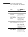
Troubleshooting Procedures . . . . . . . . . . . . . . . . . . . . . . . . . . . . . . . . . . . 5-5
For a No DC Power Condition . . . . . . . . . . . . . . . . . . . . . . . . . . . . . . 5-5
If the Control Unit Does Not Recognize the Module . . . . . . . . . . . . . 5-5
If The Calibration Results Are Unsatisfactory . . . . . . . . . . . . . . . . . . 5-5
6.
Replacement Procedures
Introduction . . . . . . . . . . . . . . . . . . . . . . . . . . . . . . . . . . . . . . . . . . . . . . . . 6-1
Equipment Needed (but not supplied) . . . . . . . . . . . . . . . . . . . . . . . . . . . 6-2
Table 6-1. Equipment Needed to Replace ECal Control Unit Major
Assemblies 6-2
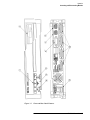
Figure 6-1. Assembly Locations . . . . . . . . . . . . . . . . . . . . . . . . . . . . . 6-3
Assembly Replacement Procedures . . . . . . . . . . . . . . . . . . . . . . . . . . . . . 6-4
Preliminary Precautions . . . . . . . . . . . . . . . . . . . . . . . . . . . . . . . . . . . 6-4
. . . . . . . . . . . . . . . . . . . . . . . . . . . . . . . . . . . . . . . . . . . . . . . . . . . . . . 6-4
To Remove The Cover . . . . . . . . . . . . . . . . . . . . . . . . . . . . . . . . . . . . 6-4
To Remove the Fan Assembly (FAN1) . . . . . . . . . . . . . . . . . . . . . . . 6-5
To Remove the IEEE 488 Adapter Board Assembly (A1) . . . . . . . . . 6-5
To Remove the Microprocessor Board Assembly (A2) . . . . . . . . . . . 6-5
HP 85060C Control Unit Contents-iii
To Remove the Control Logic Board Assembly (A3) . . . . . . . . . . . .
To Remove the 24V Power Supply Assembly (A4) . . . . . . . . . . . . .
To Remove the 5V Power Supply Assembly (A5) . . . . . . . . . . . . . .
To Remove the Display Board (A6) . . . . . . . . . . . . . . . . . . . . . . . . .
To Remove the HP-IB Switch Board (A7) . . . . . . . . . . . . . . . . . . . .
To Remove the 3.5 Inch Floppy Drive Assembly (D1) . . . . . . . . . . .
7.
6-6
6-6
6-6
6-7
6-7
6-7
Replaceable Parts
Introduction . . . . . . . . . . . . . . . . . . . . . . . . . . . . . . . . . . . . . . . . . . . . . . .
Replaceable Parts List . . . . . . . . . . . . . . . . . . . . . . . . . . . . . . . . . . . .
Ordering Information . . . . . . . . . . . . . . . . . . . . . . . . . . . . . . . . . . . .
To Order Parts...Fast . . . . . . . . . . . . . . . . . . . . . . . . . . . . . . . . . . . . .
Table 7-1. Replaceable Parts List . . . . . . . . . . . . . . . . . . . . . . . . . . .
Contents-iv HP 85060C Control Unit
7-1
7-1
7-1
7-1
7-2
1
General Information
Description
The HP 85060C Electronic Calibration (ECal) Control Unit is the controller
for electronic calibration of vector network analyzers. It performs one-port
or full two-port calibrations using the HP 8506x series of two-port electronic
calibration modules.
Using a single-connection to a variable impedance, solid-state calibration
standard (the calibration module) the HP 85060C can create either a
12-Term, two-port error model, or a 3-Term, one-port error model. The
single connection setup can be applied to connector configurations including
insertable and non-insertable. The HP 85060C is designed for use with the
following network analyzer systems::
HP 8510B
HP 8510C
HP 8719C
HP 8720C
HP 8722C
HP 8753C
HP 8753D
It houses a central processing unit with built-in firmware and controls the
entire calibration process from either the front panel of the network analyzer
or through an external system controller.
Documentation
This manual contains the information required to install, operate, program,
and service the HP 85060C Electronic Calibration Control Unit.
This manual is divided into seven major chapters:
•
•
•
•
•
•
•
CHAPTER 1 - GENERAL INFORMATION
CHAPTER 2 - INSTALLATION
CHAPTER 3 - OPERATION
CHAPTER 4 - COMMAND REFERENCE
CHAPTER 5 - TROUBLESHOOTING
CHAPTER 6 - REPLACEMENT PROCEDURES
CHAPTER 7 - REPLACEABLE PARTS
HP 85060C Control Unit 1-1
General Information
Additional copies of this manual can be ordered separately through your
nearest Hewlett-Packard office. The part number is listed on the inside of the
title page of this manual.
Specifications
Electrical and mechanical characteristics are listed in Table 1-1. These
characteristics are the standards or limits against which the instrument may
be tested.
Environmental specifications are listed in Table 1-2.
Safety Considerations
This product is a Safety Class I instrument, that is, one provided with a
protective earth terminal. The ECal Control Unit and all documentation
should be reviewed for familiarization with safety markings and instructions
before operation. Refer to the Safety Considerations page found at the
beginning of this manual for a summary of the safety information. Safety
information for installation, operation, and performance testing is found in
appropriate places throughout this manual.
Instruments Covered
by this Manual
Attached to the rear panel of this instrument is a serial number plate which
shows the instrument's model and serial numbers. The serial number is in the
form; 0000000000. The first six digits form the serial number prefix (the
first two digits are a country code, the next four are a year/week
designation). The last four digits form the suffix (a simple counting
sequence). The contents of this manual apply directly to instruments having
the serial numbers prefix(es) listed under SERIAL NUMBERS on the title
page.
Options
•
•
Option 001 provides front panel ECal module interconnections.
•
Option 910 provides an additional Operating, Programming, and Service
Manual.
•
Option 913 provides a rack mount kit which retains the Control Unit
front handles.
Accessories Supplied
Option 908 provides a rack mount kit which does not retain the Control
Unit front handles.
The accessories supplied with the ECal Control Unit are listed on the
packing slip. The line power cable is supplied in one of several
configurations, depending on the destination of the original shipment. Refer
to Power Cables in Chapter 2 of this manual.
1-2 HP 85060C Control Unit
General Information
Accessories Available
Rack Mounting Kit
Two rack mount kits are available as options (see Options above). Both rack
mounting kits contain all of the necessary hardware to allow the ECal
Control Unit to be solidly mounted into an equipment rack.
Cables
The ECal Control Unit-to-ECal Module tuner control cable is a DB-25 style,
25 pin, male-to-male, D connector. The HP part number for this and other
parts is listed in Chapter 7.
HP 85060C Control Unit 1-3
General Information
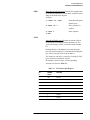
Table 1-1
Characteristics
Electrical and Mechanical
Characteristics
Performance Limits
Power Requirements:
Line Voltage
Line Frequency
90 to 250 Vac.
47 to 63 Hz
Power Dissipation:
200 VA Maximum
Safety:
Meets requirements of IEC 348
and CETM 755
Weights:
Net Weight
Shipping Weight
40 kg (18 lbs)
50 kg (22.5 lbs)
Dimensions:
100 mm (3.875 in.)
458 mm (18 in.)
569 mm (22.375 in.)
Height
Width
Length
Table 1-2
Environmental Specifications
Specification
Limits
Operating Temperaturea
Error-Corrected Temperature Range
Storage Temperature
0 to 55
b
° C (+68 τ ο +79 ° F).
± 1 ° C of measurement calibration
temperature.
− 40 τ ο 75 ° C ( −40 to + 167 ° F).
Barometric Pressure Altitude:
Operation
Storage
<4,5000 meters (15,000 feet).
<15,000 meters (50,000 feet).
Relative Humidity
Operation
Storage
Non-condensing at all times.
0 to 80% (26 ° C maximum dry bulb).
0 to 95%
EMI
Conducted susceptibility
Radiated Susceptibility
Radiated Emissions
Magnetic Emissions
CETM 765
EN 50082-1 / IEC 801-3
CISPR11
CETM 765
a. The temperature at which the calibration standards maintain performance to their specifications.
b. The allowable network analyzer ambient temperature drift during measurement calibration and during
measurements when the network analyzer correction is turned on. Also, the range over which the
1-4 HP 85060C Control Unit
2
Installation
Introduction
This chapter provides the information to install the HP 85060C Electronic
Calibration (ECal) Control Unit. Included is information pertinent to initial
inspection, power requirements, line voltage and fuse selection, power
cables, interconnection, mating connectors, operating environment, bench
operations, rack mounting, and storage and shipment. In addition, this
chapter contains the procedures for HP-IB address selection.
Initial Inspection
WARNING
To avoid hazardous electrical shock, do not turn on the instrument when there
are signs of shipping damage to any portion of the outer enclosure (covers,
panels, display).
If the shipping container or cushioning material is damaged, keep it until the
contents of the shipment are checked for completeness, and the instrument is
checked both mechanically and electrically.
Procedures for checking electrical performance are given in Chapter 3. If the
ECal Control Unit does not pass the electrical performance tests, refer to the
troubleshooting paragraphs located in Chapter 5.
Notify Hewlett-Packard if any of the following conditions exist:
•
The instrument does not pass the performance tests and, using the
troubleshooting procedures in Chapter 5, you cannot correct the
problem.
•
The instrument does not pass the performance tests and you do not wish
to troubleshoot the instrument yourself.
•
•
The shipping contents are incomplete.
There is mechanical damage or defect.
HP 85060C Control Unit 2-1
Installation
Preparation for Use
Preparation for Use
Installation Checklist
Before plugging the Control Unit into the line (Main) voltage, ensure that
the following steps are taken:
•
Check the line (Main) voltage to ensure compatibility with Control Unit
requirements (see the section on “Power Requirements”).
•
Ensure that the fuse rating is appropriate for the line voltage used. Fuse
ratings are listed in Table 2-1 on page 2-2.
•
Ensure that the power cable to be used is the required type (See the
section on “Power Cables”.
•
Plug in the power cable.
CAUTION
Before plugging this instrument into the line (Main) voltage, ensure that the
correct voltage and fuse have been selected.
Power Requirements
The Control Unit requires a power source of 90 to 250 Vac, 47 to 63 Hz
single phase. Power consumption is 200 VA maximum.
Line Voltage and Fuse
Selection
CAUTION
Before plugging this instrument into the line (Main) voltage, ensure that the
correct voltage and fuse have been selected.
Verify that the fuse is matched to the power source. See Table 2-1 for fuse
ratings. Part numbers for these and other parts are listed in Chapter 7.
Table 2-1 Fuse Ratings
LIne Voltage
Fuse Rating
115/120 VAC
4 Amperes
230/240 VAC
2 Amperes
2-2 HP 85060C Control Unit
Installation
Preparation for Use
Power Cables
WARNING
Before connecting this instrument, the protective earth terminals of this
instrument must be connected to the protective conductor of the line (Main)
power cable. The line plug shall only be inserted into a socket provided with a
protective earth circuit. The protective action must not be negated by the use
of an extension cord (power cable) without a protective conductor (grounding).
Grounding one conductor of a two conductor outlet is not sufficient
protection.
This instrument is equipped with a three wire power cable. When connected
to an appropriate ac power receptacle, this cable grounds the instrument
chassis. The type of power cable plug shipped with each instrument depends
on the country of destination. Figure 2-1 on page 2-4 Power Cable and Line
(Main) Plug Part Numbers, for the part numbers of these power cables.
Cables are available in different lengths and some with right angle plugs to
the instrument. Check with your nearest HP service center for descriptions
and part numbers for these cables.
HP 85060C Control Unit 2-3
Installation
Preparation for Use
THIS PAGE IN FOR THE POWER CABLE AND LINE PLUG PART
NUMBERS
FULL PAGE FIGURE 2-1
Figure 2-1
Power Cable and Line (Main) Plug Part Numbers
2-4 HP 85060C Control Unit
Installation
Preparation for Use
HP-IB Address
Selection for the
Control Unit
The HP-IB address for the ECal control unit is selectable from the rear panel
using the DIP switch shown in Figure 2-2. When shipped from the factory
the address of the HP 85060C is 18. HP-IB addresses from 0 to 30 can be
used.
HP-IB Address
Selection for the
Network Analyzer
The HP-IB address for the network analyzer is selectable from the rear panel
using the DIP switches shown in Figure 2-2. When shipped from the factory,
the address of the network analyzer is typically 16. Refer to your network
analyzer for the actual address. HP-IB addresses from 0 to 30 can be used.
Additional Switch
Settings
Both DIP switches contain additional switches labeled "A", "B", and 'T' or
"S". Switches "A" and "B" are for future options and should be left in the "0"
position. 'T' is a factory test switch and should be left in the "0" position. "S"
is used to specify the system controller mode; in the "1" position, the ECal
Control Unit functions as the system controller, in the "0" position, it does
not.
Figure 2-2
Interconnections
Rear Panel HP-IB Address Selection DIP Switches
The connection from the ECal Control Unit to the ECal Module is made
through Tuner Control cables. These cables are specifically designed for this
application, including EMI considerations, and are the only cables which
should be used.
HP-IB Interface Connector. The HP-IB mating connector is standard
IEEE-488. Note that the two securing screws are metric.
Operating
Environment
The operating environment for the ECal Control Unit is specified in
Table 1-2 on page 1-4 in the “Environmental Specification” section. The
operating environment for the ECal Modules is specified in the applicable
Operating and Service manual(s).
HP 85060C Control Unit 2-5
Installation
Preparation for Use
Bench Operation
The instrument has plastic feet and fold away tilt stands for convenience in
bench operation. The plastic feet are designed to ensure self aligning of
instruments when stacked. The tilt stands raise the front of the instrument for
easier viewing of the front panel.
A stacked bench setup diagram is provided as an example in Figure 2-3 on
page 2-6.
Figure 2-3 HP 85060C ECal System Bench Set-up Example
Rack Mounting
The Control Unit may be rack mounted using Hewlett-Packard sub-module
cabinets. Rack mounting information is provided with the rack mounting
kits. If the kits were not ordered with the instrument as options, they may be
ordered through the nearest Hewlett-Packard office. Refer to Options in
Chapter 1 for information regarding rack mounting kits.
2-6 HP 85060C Control Unit
Installation
Storage and Shipment
Storage and Shipment
Environment
The storage and shipment environment for the ECal Control Unit is specified
in Table 1-2 on page 1-4, Environmental Specifications. The storage and
shipment environment for the ECal Modules is specified in the applicable
Operating and Service manual(s).
Packaging
Tagging for Service.
If the instrument is being returned to Hewlett-Packard for service, please
provide the following information (attach to the instrument if possible):
•
•
•
•
•
•
•
•
•
•
•
COMPANY NAME
COMPANY ADDRESS
TECHNICAL CONTACT PERSON
TELEPHONE NUMBER and EXTENSION
MODEL NUMBER
SERIAL NUMBER
P.O. NUMBER
DATE
ACCESSORIES RETURNED WITH INSTRUMENT
TYPE OF SERVICE NEEDED (REPAIR, CALIBRATION, etc...)
FAILURE DESCRIPTION
To minimize repair time, be as specific as possible when describing the
failure. Keep the following two items in mind when describing the failure:
1. Describe what makes you think the instrument is failing. An example
might be "The network analyzer menus do not appear when I push the
RUN button on the Control Unit".
2. If the failure occurs only under certain conditions, explain how to
duplicate the failure. An example might be "The Control Unit will not
calibrate the network analyzer in the 45 MHz to 1.5 GHz range."
HP 85060C Control Unit 2-7
Installation
Storage and Shipment
Original Packaging
Containers and materials identical to those used in factory packaging are
available through Hewlett-Packard offices. Mark the container "FRAGILE"
to encourage careful handling. In any correspondence, refer to the
instrument by model number and full serial number.
Other Packaging
The following general instructions should be used for repackaging with
commercially available materials.
1. Wrap the instrument in heavy paper or ESD protective packaging. If
shipping to a Hewlett-Packard office or repair center, supply the
information mentioned above (in Tagging For Service) and attach it to
the instrument.
2. Use a strong shipping container. A double-wall carton made of 2.4 MPa
(350 psi) test material is adequate.
3. Use enough shock-absorbing material (75 to 100 mm layer; 3 to 4
inches) around all sides of the instrument to provide a firm cushion and
prevent movement in the container. Protect the front panel with an
appropriate type of cushioning material to prevent damage during
shipment.
4. Seal the shipping container securely.
5. Mark the shipping container "FRAGILE" to encourage careful handling.
2-8 HP 85060C Control Unit
3
Operation
Introduction
This chapter describes the operation and characteristics of the ECal system,
illustrates the features and functions of the standard and optional front and
rear panels of the ECal control unit and explains the setup and use of the
control unit in a system.
ESD Cautions
Always use an antistatic wrist strap when calibrating or verifying the test set
or when using the test set to measure devices. Never touch test port or ECal
module center conductors or the exposed pins of the tuner control cable.
Theory of Operation
The ECal (Electronic Calibration) system determines the systematic errors
of a vector network analyzer through a one-time connection of the ECal
module to the network analyzer port(s). The random error of connector
non-repeatability is reduced substantially through the one-time connection
when compared to the frequent connects and disconnects of the conventional
method (open / short / load).
The ECal Module is a solid state, microwave, two-port device which is
capable of establishing a plurality of reflection coefficients at each of its
ports, a low-loss transmission coefficient between its ports, and also high
isolation between its ports. This allows the module to simulate a wide variety
of conventional calibration standards. These coefficients are characterized
(pre-calibrated) for each module at the factory, and the characterization is
stored within each module. The characterization is traceable to the National
Institute of Standards and Technology (NIST).
Since the response of the ECal module is known to a high degree of accuracy
the ECal system can present one or more of these modules, use the results of
these uncorrected measurements to produce error coefficients, and provide
these error coefficients for use by the accuracy enhancement algorithms of
the network analyzer. The network analyzer can then use this data in a model
of the measurement system, measure a device, and utilize vector
mathematics to compute actual device response by removing error
contributions.
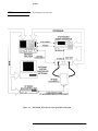
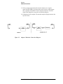
Figure 3-1 on page 3-2 shows a typical ECal system conceptual diagram.
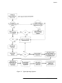
Figure 3-2 on page 3-3 shows a typical operating sequence.
HP 85060C Control Unit 3-1
Operation
NOTE
This drawing is not to scale.
Figure 3-1
HP 85060C ECal System Conceptual Block Diagram
3-2 HP 85060C Control Unit
Operation
.
Figure 3-2
l
Typical Operating Sequence
HP 85060C Control Unit 3-3
Operation
Operating Characteristics
Operating Characteristics
The operating characteristics of the ECal control unit are largely module
dependent. Table 3-1 briefly summarizes the major operating characteristics
of the ECal System, i.e.; the control unit with module(s). This table is not
intended to be an in-depth listing of all operations and ranges but gives an
idea of the instruments capabilities.
RF Input Power is +20 dBm maximum, any module, any condition.
Table 3-1
Module Part Number
Operating Characteristics
Connector Type
Frequency Range
85060-60001
7 millimeter
45 MHz to 2 GHz
85060-60002
7 millimeter
1 to 18 GHz
85062-60001
3.5 millimeter, insertable
45 MHz to 2 GHz
85062-60002
3.5 millimeter, insertable
1 to 26.5 GHz
85062-60003
3.5 millimeter, insertable male
45 MHz to 2 GHz
85062-60004
3.5 millimeter, insertable male
1 to 26.5 GHz
85062-60005
3.5 millimeter, insertable female
45 MHz to 2 GHz
85062-60006
3.5 millimeter, insertable female
1 to 26.5 GHz
85064-60001
Type N, insertable
45 MHz to 2 GHz
85064-60002
Type N, insertable
1 to 18 GHz
85064-60003
Type N, insertable male
45 MHz to 2 GHz
85064-60004
Type N, insertable male
1 to 18 GHz
85064-60005
Type N, insertable female
45 MHz to 2 GHz
85064-60006
Type N, insertable female
1 to 18 GHz
3-4 HP 85060C Control Unit
Operation
Operating Characteristics
Turn-on Information
WARNING
Before the instrument is switched on, all protective earth terminals, extension
cords, autotransformers, and devices connected to it should be connected to
protective earth grounded socket. Any interruption of the protective earth
grounding will cause a potential shock hazard that could result in personal
injury. Only fuses listed in Table 2-1 should be used. Do not use repaired fuses
or short circuited fuse holders. To do so could cause a shock or fire hazard.
Turn-on Procedure
If the control unit is already plugged in, press the line switch to ON. If the
power cable is not plugged in follow these instructions:
1. Check that the fuse rating is appropriate for the line voltage used (see
Table 2-1 on page 2-2).
2. Plug in the power cable.
3. Insure that there is no diskette in the floppy drive unless an ECal System
firmware upgrade is to performed.
4. On the front panel, press the LINE switch to ON.
When the control unit is turned on, all of the front panel LED's will come on
until the power up is complete. When power up is complete all of the LED's,
except the Line Power LED, will turn off.
If any of the LED's fail to come on, the Line Power LED fails to remain on,
or the other LED's remain on after power up, refer to the “Troubleshooting”
chapter in this manual.
HP 85060C Control Unit 3-5
Operation
Connecting and Disconnecting Modules
Connecting and Disconnecting Modules
WARNING
DO NOT connect or disconnect calibration modules while loading system
software using the floppy drive. Doing so may cause internal damage to the
control unit.
At other times, modules may be connected or disconnected during control unit
operation, although sufficient module warm-up time must be allowed before
initiation of the calibration process (see note
below).
Ensure that only HP 85060X ECal Modules are connected to the ECal control
unit module interface, and that only Tuner Control Cables provided with the
ECal Control Unit are used.
NOTE
Valid calibration can not be guaranteed without proper warm-up. Refer to
the appropriate calibration kit Operating and Service Manual.
The control unit automatically recognizes ECal modules as they are
connected. Any of the four module interconnections may be used for any
ECal module. The ECal system will recognize a module as Module A, B, C,
or D based on the module interconnection used.
Unused modules, or modules that have completed the calibration process,
may be left connected and, therefore, warmed up and ready for use. Insure
that proper care is taken with ECal modules at all times, refer to the
appropriate calibration kit Operating and Service Manual for more
information.
3-6 HP 85060C Control Unit
Operation
Connecting and Disconnecting Modules
Figure 3-3
Front and Rear Panel Features
HP 85060C Control Unit 3-7
Operation
Connecting and Disconnecting Modules
Panel Features
Front Panel and Rear
Panel Features for the
Standard and Optional
Configurations
Figure 3-3 on page 3-7 shows the ECal control unit front and rear panel
features for the standard configuration (rear panel ECal module
interconnections).
In the optional configuration (front panel ECal module connections) the
functionality of all of the features remain the same as in the standard
configuration. Only the location of the module interconnections is changed.
Refer to Figure 3-3 on page 3-7 for the following panel feature descriptions.
3-8 HP 85060C Control Unit
Operation
Connecting and Disconnecting Modules
Table 3-2
Panel Feature
HP-IB Status LED's
Panel Feature Descriptions
Descriptions
These LED's show the HP-IB interface
status as follows:
REM:
LSTN:
TALK:
SRQ:
Check HP-IB:
When illuminated this LED indicates the
interface is in the REMOTE mode.
When illuminated this LED indicates the
ECal control unit is addressed as
LISTENER.
When illuminated this LED indicates the
ECal control unit is addressed as
TALKER.
When illuminated this LED indicates the
ECal control unit is asserting a
SERVICE REQUEST.
When illuminated this LED indicates an
HP-IB (IEEE488) fault.
3.5 inch Floppy Disk Drive
Used for ECal firmware upgrades.
Floppy drive usage is not required for
operation.
Line Switch and Line LED
The line switch turns the ECal control
unit on and off. When the side of the
switch labeled 0 is depressed, the control
unit is off; 1 is on. The line LED goes on
and off with the control unit line switch.
Instrument Check LED
Continued illumination of this LED after
turn-on indicates a that the built-in
diagnostic routine has detected some
problem. Refer to Chapter 5,
Troubleshooting.
Run Switch
The RUN switch controls test set
calibration from the front panel of the
control unit. Depressing this switch
begins the calibration process. This
switch also functions as an ABORT to
stop the calibration process.
System Bus Connector
This connector is used for HP-IB
communications with the network
analyzer.
HP 85060C Control Unit 3-9
Operation
Connecting and Disconnecting Modules
Table 3-2
Panel Feature
Panel Feature Descriptions (Continued)
Descriptions
Control Unit Bus Address
Switch
This eight-pole weighted switch sets the
system bus address of the control unit.
The binary weight of each pole is
indicated on the rear panel, as are the on
and off positions. Decimal 18 is the
default setting.
Network Analyzer Bus
Address Switch
This eight-pole weighted switch sets the
system bus address of the network
analyzer. The binary weight of each pole
is indicated on the rear panel, as are the
on and off positions. Decimal 16 is the
default setting.
Line Module
This assembly houses the line cord
connector and line fuse. Pull out the
bottom of the line module cover to
replace or change the fuse.
Recommended fuse values are printed on
the rear panel.
ECal Module Interconnects
These connectors transmit the control
information to the appropriate
calibration module. The connections for
the individual modules are printed on the
rear panel (Module A,B,C,or D).
3-10 HP 85060C Control Unit
Operation
Connecting and Disconnecting Modules
Figure 3-4
Sample Network Analyzer ECal Menus
.
HP 85060C Control Unit 3-11
Operation
Connecting and Disconnecting Modules
Stand-alone (Manual) Operation
System Configuration
for Stand-alone
Operation
Accessing Menus
•
Connect the network analyzer to the ECal control unit via HP-IB cable
(when using the HP 8510, use the HP-IB connector as opposed to the
8510 Interconnect).
•
Insure ECal is set as the system controller, refer to the “Additional
Switch Settings” section in the “Installation” chapter for DIP switch
settings. Other instruments may be on the bus, but ECal must be the only
controller.
•
The ECal control unit and the network analyzer each must have unique
HP-IB addresses as defined on the ECal rear panel. Defaults are 18 for
the ECal control unit, 16 for the network analyzer.
•
DIP switch settings are only read during the boot cycle. After changing
settings, remember to cycle power to use the new settings.
All calibration menus and prompts required in the ECal process will be
displayed on the network analyzer.
•
Pressing "RUN,' on the ECal control unit initiates the calibration process
as follows:
Illuminates the ECal control unit "RUN” LED.
Accesses the ECal top level menu on the network analyzer display
using commands appropriate to the module type(s). Pressing one of
the softkeys will then access ECal sub-menus, shown in Figure 3-4
on page 3-11 The ECal menus will remain on the display until a
network analyzer action accesses a non-ECal menu, or the ECal
front panel "RUN" button is pressed.
If the ECal menus do not appear, note the condition of the ECal front panel
LED's and refer to the “Troubleshooting” chapter in this manual.
Types of Analyzers
The ECal System is designed to work with a variety of network analyzers.
Supported models are listed in the “General Information” chapter of this
manual.
Setting Calibration
Parameters
Calibration parameters define specific calibration settings or provide the user
with information on the ECal setup. Select "CALIBRATION CONFIGURE"
in the top level ECal menu to access the configuration menu (Figure 3-4 on
page 3-11.
3-12 HP 85060C Control Unit
Operation
Connecting and Disconnecting Modules
The function of each calibration parameter is as follows:
Table 3-3
Calibration Parameters
Calibration Parameter
Function
Interpolate <ON I OFF>
The Interpolate <ON I OFF> function is used to enable or disable the
frequency interpolation capability of the ECal system. With interpolation
ON (enabled), any frequencies within the span of the characterized
modules may be measured. With interpolation OFF (disabled), only
frequencies which correspond to characterization frequencies of the
modules will be allowed.
Isolation Averages
For all calibration measurements other than Isolation, calibration
measurements will be performed with the averaging value specified in the
network analyzer setup. Typically, the user will increase the number of
averages significantly if Isolation measurements are to be performed. The
Isolation Averages function is used to set the number of averages to a user
specified value (1-4096 for the HP 8510, 1-999 for the HP 87xx series).
Confidence Check
This function provides a comparison of the current ECal module
measurements vs. the factory characterization measurements. Results are
displayed using the network analyzer.
Service Functions:
Firmware Revision
This function will display the ECal system firmware revision on the
network analyzer display.
Service Functions:
Module Information
This function will display the following module information on the
network analyzer display; Model Number, Serial Number, Connector
Type, Calibration Date, Start Frequency, Stop Frequency, Number of
Frequencies, and Current Module Status.
Return
This function will return the user to the top level menu.
Selecting Modules
ECal module selection is performed by the user and should be based on
connector type and frequency range of the device-under-test. Available
modules are listed by part number and description in Table 3-1.
HP 85060C Control Unit 3-13
Operation
Connecting and Disconnecting Modules
Performing
Calibrations
The calibration type and procedure to be used depends on the type and
accuracy of measurement required for the device-under-test. The following
paragraphs provide information regarding the six available calibration types,
including the best application for each type and a brief description. For more
detailed information, refer to the appropriate network analyzer user's manual
or Hewlett-Packard application notes.
Calibrations are performed using the network analyzer configuration settings
(number of averages, etc...) with the exception of isolation calibrations
which are performed using the number of averages set in the ECal
configuration menu.
When using HP 8510 series network analyzers, calibrations cannot be
performed in the ramp sweep mode. If ramp sweep is required during
measurement of the device-under-test, calibrate in step mode and perform
measurements in ramp mode. When switching from step to ramp mode, the
message CAUTION: CORRECI ION MAY BE INVALID will be displayed.
It is the users responsibility to determine whether the change invalidates the
calibration. This can be accomplished by comparing the DUT response in
step vs. ramp mode. In general, ramp sweep is recommended only for tuning
purposes; for accurate device measurements, use step sweep.
Likewise, for HP 8720 series network analyzers, "swept" mode calibrations
are not allowed. Calibrations should be performed using sweep type
"STEPPED ON". If swept measurements are required, calibrate in step mode
(STEPPED ON) and perform measurements in swept mode (STEPPED
OITF). The network analyzer will display the message "C?" to indicate that
the sweep type was changed.
The “Performing Calibrations” section in this chapter describes the
calibration procedures in detail.
NOTE
Insertable devices are those in which the mating connectors are of the same
type, opposite gender. For example; a device where the input connector is
male, and the output connector is female. Non-lnsertable devices are those in
which the mating connectors are of the same type, and same gender. For
example; a device where both input and output connectors are
female.
For adapter calibrations using multiple (more than one) calibration modules,
all modules must be measured before adapters are measured.
3-14 HP 85060C Control Unit
Operation
Connecting and Disconnecting Modules
S11-PORT
The Sll 1-PORT calibration is best applied to high accuracy reflection
measurements of one-port devices using Port 1 of the test set.
This calibration determines the directivity, source match, and reflection
tracking error terms. These terms are then loaded into the network analyzer
to be used in vector error correction for reflection measurements.
S221-PORT
The S22 1-PORT is essentially the same calibration as the S 11 1 -PORT, but
uses Port 2 of the test set.
FULL 2-PORT
The FULL 2-PORT calibration is best applied to high accuracy magnitude
and phase measurements (including isolation) of insertable two-port devices.
This 12-term calibration provides full directivity, isolation, source match,
load match, and frequency response vector error correction for transmission
and reflection measurements. It requires measurement of all four
S-parameters and is therefore more time consuming.
OMIT ISOL 2-PORT
The OMIT ISOL 2-PORT calibration is best applied to high accuracy
magnitude and phase measurements (excluding isolation) of insertable
two-port devices.
This calibration provides all of the functionality of the FULL 2-PORT
calibration with the exception of isolation measurements, and is therefore
quicker.
ADAPTER 2-PORT
The ADAPTER 2-PORT calibration is best applied to high accuracy
magnitude and phase measurements (including isolation) of non-insertable
two-port devices. This is essentially the same calibration as the FULL
2-PORT with the exception that metrology grade adapters are used.
This 12-term calibration provides full directivity, isolation, source match,
load match, and frequency response vector error correction for transmission
and reflection measurements. It requires measurement of all four
S-parameters and is therefore more time consuming.
OMIT ISOL ADP
2-PORT
The OMIT ISOL ADP 2-PORT calibration is best applied to high accuracy
magnitude and phase measurements (excluding isolation) of non-insertable
two-port devices. This is essentially the same calibration as the OMIT ISOL
2-PORT with the exception that metrology grade adapters are used.
This calibration provides all of the functionality of the ADAPIER 2-PORT
calibration with the exception of isolation measurements, and is therefore
quicker.
HP 85060C Control Unit 3-15
Operation
Connecting and Disconnecting Modules
Optimizing Performance in the Overlapping Frequency Range
The HP 85060 series calibration kits may contain two modules, lowband and
highband, which overlap in frequency coverage. For example; the HP
85060A with Option 001 contains a lowband (0.045-2 GHz) module and a
high band (1-18 GHz) module. In the overlapping frequency range, the
module specifications may vary.
When performing measurements in the overlapping frequency range, use the
module with the best specifications over the overlapping frequency range.
Consult the HP 85060 Family Electronic Calibration System Product
Overview or the network analyzer verification software for specifications.
When performing broadband calibrations that span the overlapping
frequency range, e.g. 0.045-18 GHz, the HP 85060C control unit uses the
data from the module which was connected last during the calibration
sequence. For best performance, connect the highest performance module
last during the calibration sequence.
3-16 HP 85060C Control Unit
Operation
Calibration Procedures
Calibration Procedures
To Perform an S11
1-PORT Calibration
1. Set up the network analyzer as required (see the appropriate network
analyzer user's manual for more information).
2. Select the appropriate ECal module(s) for frequency range and
connector type (see Table 3-1 on page 3-4 for a listing).
3. Connect ECal module to the control unit to begin the warm-up. Refer to
the appropriate calibration kit Operating and Service Manual.
4. Press "RUN" on the control unit.
5. Select "S 11 1-PORT" from the top level menu of the network analyzer
(see Figure 3-4 on page 3-11 ).This will access the measurement menus.
6. Connect the module to Port 1 of the network analyzer (although module
Port A or B may be used interchangeably for single port measurements,
module Port A is preferred).
7. Press the appropriate measurement key for the module type connected.
The ECal system will now begin the calibration process, progress is
indicated on the network analyzer display. Upon calibration completion,
the module designation (Module A, B, etc...) will be underlined on the
network analyzer menu.
8. Repeat as necessary using all modules required to cover the desired
frequency band.
9. Press "SAVE CAL" on the measurement menu.
10. . Select a storage register from the network analyzer save register
menu.The HP 8510B/C will request the user to select a calset register,
this is optional on the HP 87xx series network analyzers. The ECal
control unit floppy drive can not be used for this purpose.
11. Calibration is now complete. The network analyzer display returns to the
top level menu.
HP 85060C Control Unit 3-17
Operation
Calibration Procedures
To Perform an S22
1-PORT Calibration
1. Set up the network analyzer as required (see the appropriate network
analyzer user's manual for more information).
2. Select the appropriate ECal module(s) for frequency range and
connector type (see Table 3-1 on page 3-4 for a listing).
3. Connect ECal module to the control unit to begin the warm-up. Refer to
the appropriate calibration kit Operating and Service Manual.
4. Press "RUN" on the control unit.
5. Select "S22 1-PORT" from the top level menu of the network analyzer
(see Figure 3-4 on page 3-11. This will access the measurement menus.
6. Connect the module to Port 2 of the network analyzer (although module
Port A or B may be used interchangeably for single port measurements,
module Port A is preferred).
7. Press the appropriate measurement key for the module type connected.
The ECal system will now begin the calibration process, progress is
indicated on the network analyzer display. Upon calibration completion,
the module designation (Module A, B, etc...) will be underlined on the
network analyzer menu.
8. Repeat as necessary using all modules required to cover the desired
frequency band.
9. Press "SAVE CAL" on the measurement menu.
10. Select a storage register from the network analyzer save register
menu.The HP 8510B/C will request the user to select a calset register,
this is optional on the HP 87xx series network analyzers. The ECal
control unit floppy drive can not be used for this purpose.
11. Calibration is now complete. The network analyzer display returns to the
top level menu.
3-18 HP 85060C Control Unit
Operation
Calibration Procedures
To Perform a FULL
2-PORT Calibration
1. Set up the network analyzer as required (see the appropriate network
analyzer user's manual for more information).
2. Select the appropriate ECal module(s) for frequency range and
connector type Figure 3-1 on page 3-4 for a listing).
3. Connect ECal module to the control unit to begin the warm-up. Refer to
the appropriate calibration kit Operating and Service Manual.
4. Press "RUN" on the control unit.
5. Select "FULL 2-PORT" from the top level menu of the network analyzer
(see Figure 3-4 on page 3-11). This will access the measurement menus.
6. Connect the module to the network analyzer.
7. Press the appropriate measurement key for the module type connected.
The ECal system will now begin the calibration process, progress is
indicated on the network analyzer display. Upon calibration completion,
the module designation (Module A, B, etc...) will be underlined on the
network analyzer menu.
8. Repeat as necessary using all modules required to cover the desired
frequency band.
9. Press "SAVE CAL" on the measurement menu.
10. Select a storage register from the network analyzer save register
menu.The HP 8510B/C will request the user to select a calset register,
this is optional on the HP 87xx series network analyzers. The ECal
control unit floppy drive can not be used for this purpose.
11. Calibration is now complete. The network analyzer display returns to the
top level menu.
HP 85060C Control Unit 3-19
Operation
Calibration Procedures
To Perform an OMIT
ISOL 2-PORT
Calibration
1. Set up the network analyzer as required (see the appropriate network
analyzer user's manual for more information).
2. Select the appropriate ECal module(s) for frequency range and
connector type (Table 3-1 on page 3-4 a listing).
3. Connect ECal module to the control unit to begin the warm-up. Refer to
the appropriate calibration kit Operating and Service Manual.
4. Press "RUN" on the control unit.
5. Select "OMIT ISOL 2-PORT" from the top level menu of the network
analyzer (Figure 3-4 on page 3-11). This will access the measurement
menus.
6. Connect the module to the network analyzer.
7. Press the appropriate measurement key for the module type connected.
The ECal system will now begin the calibration process, progress is
indicated on the network analyzer display. Upon calibration completion,
the module designation (Module A, B, etc...) will be underlined on the
network analyzer menu.
8. Repeat as necessary using all modules required to cover the desired
frequency band.
9. Press "SAVE CAL" on the measurement menu.
10. Select a storage register from the network analyzer save register
menu.The HP 8510B/C will request the user to select a calset register,
this is optional on the HP 87xx series network analyzers. The ECal
control unit floppy drive can not be used for this purpose.
11. Calibration is now complete. The network analyzer display returns to the
top level menu.
3-20 HP 85060C Control Unit
Operation
Calibration Procedures
To Perform an
ADAPTER 2-PORT
Calibration
1. Set up the network analyzer as required (see the appropriate network
analyzer user's manual for more information).
2. Select the appropriate ECal module(s) for frequency range and
connector type Table 3-1 on page 3-4 a listing). Also, select the
appropriate adapter(s).
3. Connect ECal module to the control unit to begin the warm-up. Refer to
the appropriate calibration kit Operating and Service Manual.
4. Press "RUN" on the control unit.
5. Select ''ADAPTER 2-PORT" from the top level menu of the network
analyzer (see Figure 3-4 on page 3-11. This will access the measurement
menus.
6. Connect the module(s) to Port 2 of the network analyzer as shown in
Figure 3-5 on page 3-22 Press the appropriate measurement key for the
module type connected. The ECal system will now begin the calibration
process, progress is indicated on the network analyzer display. Upon
calibration completion, the module designation (Module A, B, etc...)
will be underlined on the network analyzer menu.
7. Repeat as necessary using all modules required to cover the desired
frequency band.
8. Press "NEXT MENU" to continue.
9. Connect the adapter to Port 2 of the network analyzer as shown in
Figure 3-5 on page 3-22 For adapter calibrations using multiple (more
than one) calibration modules, all modules must be measured before
adapters are measured. For best accuracy, once connected to Port 2 the
adapter should remain connected until calibration is complete.
10. Connect the module between Port 1 of the network analyzer and the
adapter as shown in Figure 3-5 on page 3-22 Repeat step 7.
11. Repeat as necessary using all modules required to cover the desired
frequency band.
12. Press "SAVE CAL" on the measurement menu.
HP 85060C Control Unit 3-21
Operation
Calibration Procedures
13. Select a storage register from the network analyzer save register
menu.The HP 8510B/C will request the user to select a calset register,
this is optional on the HP 87xx series network analyzers. The ECal
control unit floppy drive can not be used for this purpose.
14. Calibration is now complete. The network analyzer display returns to the
top level menu.
Figure 3-5
Adapter Calibration Connection Diagram
3-22 HP 85060C Control Unit
Operation
Calibration Procedures
To Perform an OMIT
ISOL ADP 2-PORT
Calibration
1. Set up the network analyzer as required (see the appropriate network
analyzer user's manual for more information).
2. Select the appropriate ECal module(s) for frequency range and
connector type (refer to Table 3-1 on page 3-4 for a listing). Also, select
the appropriate adapter(s).
3. Connect ECal module to the control unit to begin the wann-up. Refer to
the appropriate calibration kit Operating and Service Manual.
4. Press "RUN" on the control unit.
5. Select "OMIT ISOL ADP 2-PORT" from the top level menu of the
network analyzer (see Figure 3-4 on page 3-11). This will access the
measurement menus.
6. Connect the module(s) to Port 2 of the network analyzer as shown in
Figure 3-5 on page 3-22.
7. Press the appropriate measurement key for the module type connected.
The ECal system will now begin the calibration process, progress is
indicated on the network analyzer display. Upon calibration completion,
the module designation (Module A, B, etc...) will be underlined on the
network analyzer menu.
8. Repeat as necessary using all modules required to cover the desired
frequency band.
9. Press "NEXT MENU" to continue.
10. Connect the adapter to Port 2 of the network analyzer as shown in
Figure 3-5 on page 3-22.
NOTE
For adapter calibrations using multiple (more than one) calibration modules,
all modules must be measured before adapters are measured. For best
accuracy, once connected to Port~2 the adapter should remain connected
until calibration is complete.
11. Connect the module between Port 1 of the network analyzer and the
adapter as shown in Figure 3-5 on page 3-22 Repeat step 7.
12. Repeat as necessary using all modules required to cover the desired
frequency band.
13. Press "SAVE CAL" on the measurement menu.
14. Select a storage register from the network analyzer save register
menu.The HP 8510B/C will request the user to select a calset register,
this is optional on HP 87xx series network analyzers. The ECal control
unit floppy drive can not be used for this purpose.
HP 85060C Control Unit 3-23
Operation
Calibration Procedures
15. Calibration is now complete. The network analyzer display returns to the
top level menu.
Performing the
Confidence Check
The CONFIDENCE CHECK function is provided as a means of checking
the accuracy of a stored (saved) calibration. Each ECal module has a special
state, the confidence state, which has been pre-measured. The pre-measured
corrected data has been stored in nonvolatile, or permanent, module
memory.
The confidence check has been designed for use after a two-port calibration.
It can, however, be used after a one-port calibration provided the unused
module port is terminated with a 50 ohm load with a minimum of 30 dB of
return loss.
When the confidence check is selected, the ECal control unit will read the
pre-measured corrected data, store it into network analyzer memory, and
then use the calibration stored in the network analyzer to make a corrected
measurement of the confidence state. These measurements are then
presented in a graphical way.
The graphical options available depend on the type of calibration being
checked. If the confidence check is used for a two-port calibration, all four
S-parameters are available. For a one-port calibration, the reflection option
S 11 or S22 will be available, depending on the calibration type.
In any case, the data may be displayed in one of two ways:
•
With the "BOTH" option, the pre-measured data and the current data are
displayed, and a visual comparison of these measurements may be
made.
•
With the "DIV" option, only a ratio of the pre-measured data to the
current data is displayed.
The confidence check will change many network analyzer parameters for
data presentation. Choosing "DONE CHECK" will complete the confidence
check and restore the network analyzer conditions—with the exception of
data in memory that were in effect before the confidence check was invoked.
3-24 HP 85060C Control Unit
Operation
Calibration Procedures
To Perform a
Confidence Check
1. Set up the network analyzer as required (see the appropriate network
analyzer user's manual for more information).
2. Select the appropriate ECal module(s) for frequency range and
connector type (see Table 3-1 on page 3-4 for a listing). Also, select the
appropriate adapter(s).
3. Connect ECal module to the control unit to begin the warm-up. Refer to
the appropriate calibration kit Operating and Service Manual.
4. Press "RUN" on the control unit.
5. Select "CALIBRATE CONFIGURE" from the top level menu of the
network analyzer (see Figure 3-4 on page 3-11). This will access the
configuration menu.
6. Select "CONFIDENCE CHECK" from the configuration menu. This
will access the confidence check module selection menu.
7. Connect the module(s) to the network analyzer as appropriate.
8. Select a module from the module selection menu. This will access the
parameter selection menu.
9. Select a parameter and / or a display option from the parameter selection
menu. This will cause a series of events which include downloading the
corrected pre-measured parameter data and measurement of the
confidence state. The data will be presented in the manner selected.
10. If another parameter or display option is desired, repeat step 9.
11. When finished, select "DONE CHECK". This will reset the network
analyzer to the conditions that were in e*ect when the confidence check
was invoked. If this is not done, noncritical scales, parameters, and
display options may be left in place.
12. Confidence check is now complete. The network analyzer display
returns to the top level menu.
HP 85060C Control Unit 3-25
Operation
Remote Operation
Remote Operation
The ECal system is capable of remote operation via the Hewlett-Packard
Interface Bus (HP-IB) and is compliant with EKE 488.2-1987, IEEE Standard Codes, Formats, Protocols, and Common Commands for use with
ANSI/IEEE Standard 488.2-1987.
Instructions pertinent to HP-IB operation cover considerations and instructions specific to remote operation including capabilities, addressing, input
and output formats, the status byte, and service requests.
System Configuration
for Remote Operation
•
Connect the host computer and network analyzer to the ECal control
unit via HP-IB cable (when using the HP 8510, use the HP-IB connector
as opposed to the 8510 Interconnect).
•
Insure ECal is not set as the system controller, see paragraph 2-3.7 for
DIP switch settings. Other instruments may be on the bus, but ECal must
be the only controller. The host computer, the ECal control unit, and the
network analyzer each must have unique HP-IB addresses as defined on
the ECal rear panel. Defaults are 18 for the ECal control unit, 16 for the
network analyzer. Refer to the “Additional Switch Settings” section in
the “Installation” chapter of this manual for DIP switch settings.
NOTE
DIP switch settings are only read during the boot cycle. After changing
settings, remember to cycle power to use the new settings.
Communicating with
Host Computers
ECal functions can be grouped into two categories, those which require
active control (specifically, ECal commands which talk to the network analyzer) and those which do not. The following seven commands require active
control:
•
•
•
•
•
•
•
DISP:MENU:NAME
SENS:CORR:COLL:ACQ
SENS:CORR:COLL: SAVE
SENS:CORR:COLL:RESU
SENS:CORR:COLL: DONE
SENS:CORR:COLL: NEXT
SENS:CORR:COLL:PRI
All other commands are handled solely by the ECal control unit, and therefore do not require active control.
3-26 HP 85060C Control Unit
Operation
Remote Operation
Sending Commands
Which Require Pass
Control
Commands listed in the “Sending Commands Which Do Not Require Pass
Control” section in this chapter require access to the network analyzer, and
therefore require that the host pass control to the ECal control unit.
The following example sends the DISP:MENU:NAME ECAL command
which tells the control unit to display the top level ECal system menu.
10
OUTPUT 718;.DISP:MENU:NAME ECAL
20
CALL Pass_control
30
END
40
SUB Pass_control
50
OUTPUT 718;”*ESR?”
60
ENTER 718;Esr
70
IF NOT BIT (Esr,1) THEN ! Ensure that ECal wants control
80
90
! Read the Event Status Register
PRINT “ECal does not want control”
ELSE
100
REMOTE 7
110
PASS CONTROL 718
120
PRINT “CONTROL PASSED TO ECAL
130
LOOP
! Pass control to ECal
140
STATUS 7,3;Stat
! Monitor Interface Status
150
EXIT IF BIT (Stat,6)! Finish when Control is returned
160 END LOOP
170 PRINT “CONTROL RETURNED FROM ECAL”
180
END IF
190
SUBEND
When this example is run, the DISP:MENU:NAME command is sent in line
10. You should then see the "CONTROL PASSED TO ECAL” message on
the host, and the top level ECal menu on the network analyzer display. You
may move through the ECal menus as desired. When finished, exit the ECal
menus (press the ECal "RUN" key or select a network analyzer menu). The
message "CONTROL RETURNED FROM ECAL~ will be displayed on the
host.
NOTE
The ECal system will pass control back to the host when it is finished with
the network. It expects to find the host at address 21 unless that address has
been changed with the *PCB command. If your host is not at address 21, you
should include an OUTPUT statement with the * PCB command before line
10 in this example.
HP 85060C Control Unit 3-27
Operation
Remote Operation
Sending Commands
Which Do Not Require
Pass Control
Most ECal commands are sent and received very simply as shown in the following example:
10
20
30
40
DIM Iden$[80]
OUTPUT 718; “ * IDN?”
ENTER 718; Iden$
END
Line 10 sends a command to the ECal control unit requesting it's identity
(identification query). Line 20 reads the string back from the ECal control
unit.
Setting Calibration
Parameters for
Remote Operation
The majority of the parameters used for calibration are configured by setting
the network analyzer as desired before initiating the calibration, but, as in the
manual measurement mode, there are several parameters which are specific
to ECal and may need to be set. They are:
•
•
Selecting Modules for
Remote Operation
EC AL:FINT
Frequency Interpolation
EC AL: IAV
Isolation Averages (see “Setting Calibration
Parameters”) for details.
ECal module selection is performed by the user and should be based on connector type and frequency range of the device-under-test. Available modules
are listed by part number and description in Table 3-1 on page 3-4.
3-28 HP 85060C Control Unit
Operation
Remote Operation
Performing
Calibrations by
Remote Operation
The calibration type and procedure to be used depends on the type and
accuracy of measurement required for the device-under-test. See the
“Performing Calibrations” section of this chapter it provides information
regarding the six available calibration types, the best application for each
type, and a brief description. For more detailed information, refer to the
appropriate network analyzer user's manual or Hewlett-Packard application
notes. In all cases, performing calibrations by Remote Operation is very
similar to performing calibrations by Stand-alone Operation.
A host application may direct a calibration in one of two fashions as follows:
1. Initiate the calibration remotely and then allow the user to use ECal
menus to measure each module.
2. The application may control each step of the calibration, prompting the
user to connect specific modules.
Host Initiated Manual
Calibration
If an application requires a calibration, but the parameters (module, frequency range, connector type) vary from day to day, it may be appropriate
for the application to initiate a calibration, and then allow the user perform
the calibration. An example of this is as follows:
10
20
30
40
50
60
OUTPUT 716;”PRES”
! Commands to set up MWA
OUTPUT 716;”STAR 2 GHZ;STOP 18 GHZ
OUTPUT 718;"DISP:MENU:NAME FULL” ! Goto FULL 1-PORT Menu
CALL Pass_control
! The application continues here
END
See the “Sending Commands Which Require Pass Control” section for the
listing of the Pass_control subprogram.
This example will set up the network analyzer as required for the measurement, and then command the ECal control unit to begin a FULL 2-PORT
calibration. The Module Selection menu will be displayed on the network
analyzer, and the user will be able to select and calibrate using appropriate
modules. When the calibration is completed, control will be returned to the
host application.
HP 85060C Control Unit 3-29
Operation
Remote Operation
Host Directed Full
Calibration
For many production applications, the same exact calibration procedures
will be used day in and day out. For these, it is appropriate to have the application prompt the user with the specific steps to follow. This sample
executes a FULL 2-PORT calibration remotely.
10
20
30
40
50
60
70
80
90
100
110
120
130
OUTPUT 716;”PRES”! Commands to set up the network analyzer
OUTPUT 716;”STAR 2 GHZ;STOP 18 GHZ”
OUTPUT 718;”SENS:CORR:COLL:METH FULL” ! Start Cal
INPUT “Connect Module A to NWA, then Press ENTER”,Dum$
OUTPUT 718;”SENS:CORR:COLL:ACQ A” ! Cal with Module A
CALL Pass_control
INPUT “Connect Module B to NWA, then Press ENTER”,Dum$
OUTPUT 718;”SENS:CORR:COLL:ACQ B”! Cal with Module B
CALL Pass_control
OUTPUT 718;”SENS:CORR:COLL:SAVE 5” ! Save in calset 5
CALL Pass_control
! The application continues here
END
See paragraph 3-8.2.1 for the listing of the Pass_control subprogram.
Host Directed Adapter
Calibration
The adapter calibration can be controlled remotely as shown in the following
example:
! Set up NWA
20 OUTPUT 716;”STAR 2 GHZ;STOP 18 GHZ”
30 OUTPUT 718;”SENS:CORR:COLL:METH FULL” ! Start Cal
40 INPUT “Connect Module A to NWA Port 2, then Press ENTER",Dum$
50 OUTPUT 718;”SENS:CORR:COLL:ACQ A” ! Cal with Module A
60 CALL Pass_control
70 INPUT “Connect Module B to NWA Port 2, then Press ENTER”,Dum$
80 OUTPUT 718;”SENS:CORR:COLL:ACQ B”! Cal with Module
90 CALL Pass_control
100 OUTPUT 718; ”SENS:CORR:COLL:NEXT” ! Go to 2nd phase
110 CALL Pass_control
120 PRINT “Connect Adapter to NWA Port 2”
130 INPUT “Connect Module A between Port 1 and Adapter, then Press
ENTER”,Dum$
140 OUTPUT 718;”SENS:CORR:COLL:ACQ A” ! Cal with Module A
150 CALL Pass_control
160 NPUT “Connect Module A between Port 1 and Adapter, then Press
ENTER”,Dum$
170 OUTPUT 718;”SENS:CORR:COLL:ACQ B” ! Cal with Module B
180 CALL Pass_control
190 OUTPUT 718;”SENS:CORR:COLL: SAVE 5”!Save in Calset 5
200 CALL Pass_control
210
! The application continues here
10 OUTPUT 716;”PRES”
3-30 HP 85060C Control Unit
Operation
Remote Operation
220 END
See the “Sending Commands Which Require Pass control” section for the
listing of the Pass_control subprogram.
HP 85060C Control Unit 3-31
Operation
Remote Operation
Responding to the
ECal "RUN" Key
For a particular application, it might be desirable to have the user calibrate
the analyzer manually. The sample in paragraph 3-8.5.1 is one possible
means of this. This example shows another method, where the user will
press the ECal control unit "RUN" button when they wish to perform a calibration. The control unit will then interrupt the application program to get
control and allow the user to perform the calibration.
10
!
Set up ECal masks, and interrupt handlers
20
OUTPUT 718; “*SRE 32”
!
Enable Interrupt on Event Status Bit
30
OUTPUT 718; “*ESE 2”
!
Enable Interrupt on Request Control
40
ON INTR 7,2 CALL Srq_handler
50
LOOP
!
The application continues here?
!
Dummy application
60
PRINT “Count is “;I
70
I=I+1
80
END LOOP
90
END
100
SUB Srq_handler
110
IF NOT BIT(SPOLL(718),5) THEN
120
PRINT “ECal is not causing Interrupt”
130
ELSE
140
OUTPUT 718;”*ESR?”
150
ENTER 718;Esr
160
IF NOT BIT (Esr,1) THEN
170
180
!
Read the Event Status Register
!
Ensure that the ECal wants Control
PRINT “ECal does not want control”
ELSE
190
PASS CONTROL 718
!
Pass control to ECal
200
PRINT “CONTROL PASSED TO ECAL”
210
LOOP
220
STATUS 7,3;Stat
!
Monitor Interface Status
230
EXIT IF BIT (Stat,6)
!
Finish when Control is returned
240
END LOOP
250
PRINT “CONTROL RETURNED FROM ECAL”
260
END IF
270
END IF
280
SUBEND
3-32 HP 85060C Control Unit
4
Command Reference
Command Types
HP-IB (Hewlett-Packard Interface Bus) commands are separated into two
types: SCPI (Standard Commands for Programmable Instruments) commands and IEEE 488.2 Common Commands.
SCPI Command
Format
The SCPI commands perform functions like setting parameters, making
measurements, and querying instrument states or retrieving data. A subsystem command structure is a hierarchical structure that usually consists of
a top level (or root) command, one or more lower level commands, and their
parameters. The following example shows part of a typical subsystem:
DISP:MENU[:NAME] <ECAL|CONF||SERV|MODI|etc...>
DISPis the root command, : MENU is the second level command, and
[:NAME] is a third level command with parameters.
In this manual the following conventions are used:
Common Command
Format
•
Bracketed commands, for example [: NAME], indicate defaults, and are
therefore optional.
•
•
Commands in angle brackets, <MODI>, are required parameters.
•
Lowercase choices, n, indicate that a value must be specified.
Commands separated by vertical lines within angle brackets,
<SERVIMODI>, indicate available choices.
The IEEE 488.2 standard defines the Common Commands that perform
functions like reset, self-test, status byte query, etc... Common commands
are four or five characters in length, always begin with an asterisk character
(*), and may include one or more parameters. The command keyword is separated from the first parameter by a space character. Some examples of common commands are shown below:
HP 85060C Control Unit 4-1
Command Reference
*CLS, *IDN?, *SRE
SCPI Command
Reference
This section describes the SCPI commands for the System Instrument. Commands are listed alphabeticallyby subsystem and also within each subsystem. Commands which require pass control in the remote operation mode
are identified as such.
DISPlay:MENU
Requires PassControl
DISP:MENU[:NAME]<ECAL|CONF|SERV|MODI|
SllC|S22C|FULL|QFUL|ADAP|QAD|CCH|CCHA|
CCHB|CCHC|CCHD>
The DISP:MENU subsystem commands provide the user
with local access to the ECal menu functions via the front
panel and CRT of the network analyzer. The available
selections follow.
:MENU ADAPter
The module select menu for ADAPTER
calibrations.*
2-PORT
:MENU CCH
The module select menu for the confidence check
:MENU CCHA
The parameter select menu for the Module A confidence
check.
:MENU CCHB
The parameter select menu for the Module B confidence
check.
:MENU CCHC
The parameter select menu for the Module C confidence
check.
:MENU CCHD
The parameter select menu for the Module D confidence
check.
:MENU CONFigure
The configuration menu.
*
See SENS:CORR:COLL:METH for more information.
4-2 HP 85060C Control Unit
Command Reference
:MENU ECALibration
The top level ECal menu.
:MENU FULL
The module select menu for FULL 2-PORT
calibrations.*
:MENU MODInformation
The module information menu.
:MENU SERVice
The service menu.
MENU S11C
MENU S22C
The module select menu for S11 1-PORT calibrations.*
The module select menu for S22 1-PORT calibrations.*
MENU QADapter
The module select menu for OMIT ISOL ADP 2-PORT
calibrations.*
MENU QFUL
The module select menu for OMIT ISOL 2-PORT
calibrations.*
HP 85060C Control Unit 4-3
Command Reference
ECALibration
ECALibration
ECAL
The ECAL subsystem commands access the functions
and variables used to perform the electronic calibration.
ECAL:FINTinterpolate
ECAL:FINT <ON|OFF|?>
The ECAL:FINT subsystem command is used to enable or
disable the frequency interpolation capability of the ECal
system.
:FINT ON
With interpolation enabled (ON), any frequencies within
the span of the characterized module may be measured.
:FINT OFF
With interpolation disabled (OFF), only those
frequencies which correspond to the actual
characterization frequencies of the ECal module will be
allowed.
:FINT?
Returns a 1 if frequency interpolation is enabled, returns
a 0 if frequency interpolation is disabled.
ECAL:IAVerages
ECAL:IAV <numeric_value|?>
The ECAL:IAV command allows the ECal system to
override, for isolation calibrations, the averaging value
specified in the network analyzer setup.
For all other calibrations, measurements are performed
using the averaging value specified in the network
analyzer setup. However, isolation calibrations typically
require significantly increased averaging.
This command will set the averaging value used for
isolation measurements to the specified numeric value. If
the numeric value is not included, the user will be
prompted to enter the desired averaging value using the
active entry capability of the network analyzer (softkeys).
:IAV?
ECAL:IAV?
The ECAL:IAV? command returns the averaging value
specified in the network analyzer setup.
4-4 HP 85060C Control Unit
Command Reference
SENSe: CORRection: COLLect
SENSe: CORRection: COLLect
SENS:CORR:COLL
The SENS:CORR:COLL subsystem commands are used by
the host computer to initiate, measure, and bring closure
to calibrations.
: ACQuire
SENS:CORR:COLL:ACQ <module_name>
Requires Pass Control
This command is used to initiate the measurement of a
specific ECal module (module A, B, C, or D) after a
calibration or confidence check has begun using
SENS:CORR:COLL:METH.
: DONE
SENS:CORR:COLL: DONE
Requires Pass Control
This command is used to indicate completion of the
confidence check, set the module to its idle state, and
restore the network analyzer display,
:METHod
SENS:CORR:COLL:METH <method_name>
The SENS:CORR:COLL:METH subsystem commands
initiate a calibration of the specified type. Use this
command to initiate a calibration from the host computer
only if the host will also be specifying the modules to be
measured (SENS:CORR:COLL:ACQ), and executing the
save (SENS:CORR:COLL: SAVE).
Use the DISP:MENU:NAME command to have the host
initiate the calibration. The the user will be prompted to
select modules using the active entry capability of the
network analyzer (softkeys).
HP 85060C Control Unit 4-5
Command Reference
SENSe: CORRection: COLLect
:METH ADAPter
This command is used to initiate the ADAPTER 2-PORT
calibration. This is a two-step process for performing
non-insertable calibrations using an insertable ECal
module with an adapter. The first step uses the ECal
module connected directly to Port 2 of the network
analyzer to establish the S22 reference plane. The second
step of the process uses the ECal module connected to
Port 1 of the network analyzer, and an appropriate
adapter connected between the ECal module and Port 2
of the network analyzer.
:METH CCH
This command is used to perform a confidence check of
the network analyzer calibration.
:METH FULL
This command is used to initiate the FULL 2-PORT
calibration of the network analyzer including the
isolation terms. After selecting this function, all of the
necessary modules must be connected and measured
before saving the calibration coefficients to the network
analyzer's calibration registers.
:METH QADapter
This command is used to initiate the OMIT ISOL ADP
2PORT calibration of the network analyzer. This
calibration is the same as the ADAPTER 2-PORT
calibration with the exception that isolation
measurements are omitted.
:METH QFUL
This command is used to initiate the OMIT ISOL
2-PORT calibration of the network analyzer. This
calibration is the same as the FULL 2-PORT calibration
with the exception that isolation measurements are
omitted.
:METH S11C
This command is used to initiate the S11 1-PORT
calibration using Port 1 of the network analyzer. After
selecting this function, all of the necessary modules must
be connected and measured before saving the calibration
coefficients to the network analyzer's calibration
registers.
4-6 HP 85060C Control Unit
Command Reference
SENSe: CORRection: COLLect
:METH S22C
This command is used to initiate the S22 1-PORT
calibration using Port 2 of the network analyzer. After
selecting this function, all of the necessary modules must
be connected and measured before saving the calibration
coefficients to the network analyzer's calibration
registers.
:NEXt
SENS:CORR:COLL:NEX
Requires Pass Control
This command is used to progress from Phase 1 to Phase
2 of the adapter calibration. All Phase 1 measurements
must be completed or errors will be generated.
:PARameter
SENS:CORR:COLL: PAR <Sll|S21|S12|S22>
This command is used to determine which parameter is
displayed when the SENS:CORR:CORR:ACQ command is
executed.
:PRIor
SENS:CORR:COLL:PRI
Requires Pass Control
This command is used to return from Phase 2 to Phase 1
of the adapter calibration. Any completed Phase 1
measurements will be lost.
:RESume
SENS:CORR:COLL:RES
Requires Pass Control
This command is used to resume a calibration already in
process.
:SAVE
SENS:CORR:COLL: SAVE [calset number]
Requires Pass Control
This command is used to end the calibration process after
all required modules have been measured, and then load
the error coefficients into the network analyzer.
If a calset number is included in the command, the
calibration is saved in that register. Otherwise, the user is
prompted via the standard network analyzer menus.
HP 85060C Control Unit 4-7
Command Reference
SENSe: CORRection: COLLect
:VIEW
SENS:CORR:COLL: VIEW <BOTH|DIV>
Requires Pass Control
This command is used to set the display mode when the
SENS:CORR:CORR:ACQ command is executed.
:VIEW BOTH
Displays DATA & MEMORY.
:VIEW DIV
Displays DATA divided by MEMORY.
4-8 HP 85060C Control Unit
Command Reference
SYST em
SYST em
Subsystem Syntax
SYST
The SYST subsystem commands access certain standard
SCPI commands not related to instrument performance.
:ERRor?
SYST:ERR?
Returns the error number and message associated with
the latest actions of the ECal system. The errors will be
contained in a two element FIFO (First In, First Out)
queue. If more than 2 errors occur between readings by
the host, the most recent errors will be lost, and the
second entry will be replaced with the QUEUE OVERFLOW
message.
See Table 4-1 for a listing of error messages.
:PRESet
SYST:PRES
Presets the ECal system to its power-up state. Equivalent
to the *RST command.
:VERSion?
Returns the SCPI version to which the instrument
complies. The returned value is 1994.0.
HP 85060C Control Unit 4-9
Command Reference
Common Command Reference
Common Command Reference
This section describes the EEE-488.2 Common Commands that can be used
to program instruments in the mainframe. For additional information on any
Common Commands, refer to the IEEE Standard 488.21987.
*CLS
Clear Status. This command clears the status byte register
(STB) and the event status register (ESR) for the
instrument.
*ESE [n]
Set Event Status Enable Mask. Enables specific bits to be
summarized in the ESB bit of the status byte. See *ESR?
for more details.
*ESE?
Read Event Status Enable Mask. Places the current value
of the event status enable register in the output queue.
*ESR?
Read Event Status Register. Bit numbers, decimal values,
and corresponding functions are shown in Table 4-1.
Table 4-1
ECal Event Status Register
BIT
#
DECIMAL
VALUE
FUNCTION
7
128
Power ON
6
63
User Request (not used)
5
32
Command Error
4
16
Execution Error
3
8
Device Error
2
4
Query Error
1
2
Request Control
0
1
Operation Complete
4-10 HP 85060C Control Unit
Command Reference
Common Command Reference
* IDN?
Identification Ouery. Returns a string containing the
current revision of the ECal firmware in the following
format:
Hewlett Packard, 8 5 0 6 0C, O, xx . YY
The revision varies with the revision of the firmware
installed in the system. This is the only indication of
which version of firmware is in use. The major number
(XX) indicates whether there have been functional
changes made in the firmware. The minor number (YY)
indicates only that bug fixes and minor changes have
been made.
Example: Get the ID fields from the system and print
them;
10 DIM A$ [50]
Dimension string for ID
fields
20 OUTPUT 718; "*IDN?"
Sends identification
query
30 ENTER 718;A&
Places ID fields in string
40 PRINT A&
Print ID fields
50 END
*OPC
Operation Complete. This command prompts ECal to
generate the operation complete message in the Event
Status Register (ESR) when all pending operations are
complete.
*OPC?
Operation Complete Ouery. Since ECal processes all
commands sequentially, this command will always place
an ASCII 1 in the ECal output buffer when all pending
operations are complete.
*PCB [n]
Set the Passbook Address. Sets the address of the host
computer. In the non-system controller mode, the ECal
Control Unit will return active control to the address
specified by this command. The default value is 21.
HP 85060C Control Unit 4-11
Command Reference
Common Command Reference
*RST
Reset Command. Resets an instrument to a known state
(the power-on state) as follows:
•
•
•
•
Aborts all pending operations.
Disables the *OPC and *OPC? modes.
Resets the Frequency Interpolation to "ON".
Resets Isolation Averages to the default values.
*RST (does not effect):
•
•
•
•
•
The state of the HP-IB interface.
The HP-IB address.
The output queue.
The Status Request register.
Calibration data.
*SRE [n]
Service Request Enable. When a service request occurs,
it sets a corresponding bit in the Status Byte Register.
This happens whether or not the event has been enabled
(unmasked) by *SRE. The *SRE command allows you to
identify which of these events will assert an HP-IB
service request (SRQ).
When an event is enabled by *SRE and that event occurs,
it sets a bit in the status byte register and issues an SRQ
to the computer (sets the HP-IB SRQ line true). You
enable an event by specifying its decimal weight for [n].
To enable more than one event, specify the sum of the
decimal weights.
Example:
OUTPUT 718;”*SRE 9”
Enables bits 0 & 3.
Respective weights are
1+8=9
4-12 HP 85060C Control Unit
Command Reference
Common Command Reference
*SRE?
Status Register Enable Ouery. Returns the weighted sum
of all enabled (unmasked) events (those enabled to assert
SRQ) in the Status Byte Register.
Example:
Sends Status Register
10 OUTPUT 718;”*SRE?"
Enable Query
Places response in
20 ENTER 718; A
variable
Prints response
30 PRINT A
40 END
*STB?
Status Byte Enable Query. Returns the current value of
the status byte including the master summary bit. The
serial poll response is this byte which includes the RSV
bit.
Reading this byte with STB? does not clear the status
byte, the master summary bit, or the RSV bit. Reading this
byte with a serial poll clears only the RSV bit.
The status byte can only be cleared by clearing all of the
bytes which are summarized within it.
Bit numbers, decimal values, and corresponding
functions are shown in Table 4-2.
Table 4-2
ECal Status Byte Register
BIT
#
DECIMAL
VALUE
FUNCTION
7
128
not used
6
64
RSV bit - Master Summary bit (MSS)
5
32
Event Status Summary (ESB)
4
16
Message Available (MAV)
3
8
not used
2
4
Error Queue
1
2
not used
0
1
not used
HP 85060C Control Unit 4-13
Command Reference
Common Command Reference
*TST?
Self Test. Returns a O indicating that no internal failures
have occurred.
*WAI
Wait to Continue. This command prevents the execution
of any further commands until pending operations are
complete.
Since ECal processes commands sequentially, this
command has no effect on ECal operation. It is processed
for compliance with EKE - 88.2 standards.
4-14 HP 85060C Control Unit
Command Reference
Quick Reference for SCPI and IEEE-488 Commands
Quick Reference for SCPI and IEEE-488
Commands
The following tables summarize SCPI and IEEE 488.2 Common Commands
for the HP 85060C ECal Control Unit.
Table 4-3
SCPI Commands - Quick Reference
Command
Description
DISP:MENU [:NAME]
Display the specified [NAME]ECal menu
on the network analyzer.
ECAL:IAV <numeric_value|?>
Sets amount or returns value of
averages for use in isolation
measurements.
ECAL:FINT <ON|OFF|?>
Enable or disable frequency
interpolation, or show current
frequency interpolation status.
SENS:CORR:COLL:ACQ <A|B|C|D>
Initiate the measurement of a
specific ECal module
SENS:CORR:COLL:DONE
Used to indicate confidence
check completion, set the
module to its idle state, and
restore the network analyzer
display.
SENS:CORR:COLL:METH <method_name>
Performs the appropriate
(specified) calibration.
SENS:CORR:COLL:METH ADAP
Performs an ADAPTER
2-PORT calibration.
SENS:CORR:COLL:METH CCH
Performs a CONfIDENCE
CHECK of the NWA
calibration.
SENS:CORR:COLL:METH FULL
Performs a FULL 2-PORT
calibration including the
isolation terms.
SENS:CORR:COLL:METH QAD
Performs an OMIT ISOL ADP
2-PORT calibration
HP 85060C Control Unit 4-15
Command Reference
Quick Reference for SCPI and IEEE-488 Commands
Table 4-3
SCPI Commands - Quick Reference
SENS:CORR:COLL:METH QFUL
Performs an OMIT ISOL
2-PORT calibration.
SENS:CORR:COLL:METH S11C
Performs an S11 1-PORT
calibration using NWA Port 1
SENS:CORR:COLL:METH S22C
Performs an S22 1-PORT
calibration using NWA Port 2.
SENS:CORR:COLL:MEX
Progress from calibration Phase
1 to Phase 2
SENS:CORR:COLL:PAR
Used to determine which
parameter is displayed when the
SENS:CORR:COLL:ACQ
command is executed.
SENS:CORR:COLL:PRI
Return to calibration Phase I
from Phase 2.
SENS:CORR:COLL:RES
Resume a calibration already in
process
SENS:CORR:COLL:SAVE [calset number]
End the calibration process, load
the error coefficients into the
network analyzer.
SENS:CORR:COLL:VIEW <BOTH|DIV>
Used to set the display mode
when the
SENS:CORR:COLL:ACQ
command is executed.
SYST:ERR?
Return the latest error number
and message.
SYST:VERS?
Return the ECal firmware
revision. Equivalent to the
IDN command.
SYST:PRES
4-16 HP 85060C Control Unit
*
Preset the ECal system to its
power-up state. Equivalent to the
*RST command.
Command Reference
Quick Reference for SCPI and IEEE-488 Commands
Table 4-4
Common Commands - Quick Reference
Command
Description
*CLS
Clear Status. Sets the ECal Control Unit status
byte to 0.
*ESE
Set Event Status Enable mask.
*ESE?
Read Event Status Enable mask.
*IDN?
Read Event Status Enable register.
*OPC
Identification Query. Returns the ECal
firmware revision. Equivalent to the
SYST:VERS? command.
*OPC?
Operation Complete
*PCB [n]
Operation Complete Query.
*RST
Presets the ECal system to its power-up state.
Equivalent to the SYST:PRES command.
*SRE [n]
Service Request Enable. Masks selected bits
of the status byte.
*SRE?
Status Register Enable Query. Returns the
current value of the Serial Poll Mask.
*STB?
Status Byte Enable Query.
*TST?
Self Test.
*WAI
Wait to Continue.
HP 85060C Control Unit 4-17
Command Reference
Quick Reference for SCPI and IEEE-488 Commands
4-18 HP 85060C Control Unit
5
Troubleshooting
Introduction
Instrument problems usually fall into three general categories: operator
errors, turn-on errors, and run-time errors. The troubleshooting strategy is
different for each category.
Operator Errors
Apparent failures often result from operator errors. Refer to Chapter 3,
Operation, for proper operation information.
Turn-on Errors and Run-Time Errors:
An error signified by continued illumination of the Instrument Check LED at
turn-on or during otherwise normal operation, with or without illumination
of other front panel LED's, indicates that the built-in diagnostic routine has
detected some problem. Turn the instrument off, then on again. If the error
repeats, see the “Troubleshooting Sequence” section in this chapter.
information there can be used to isolate a setup error, operator error, or
failure of one of the major assemblies in the instrument. Additionally,
problems may occur that are not indicated by front panel LED status. See the
“Troubleshooting Procedures” section in this chapter.
Recommended Test
Equipment
n addition to the equipment listed in Table 6-1 on page 6-2, a voltmeter may
be required for troubleshooting.
Diagnostic Software
A factory test diagnostic program is built into firmware. Instructions for use
are included where applicable in the troubleshooting procedures below.
Troubleshooting
Sequence
Prior to troubleshooting, please insure that normal ECal
operation—described in the “Operation” chapter—is fully understood.
Figure 3-2 on page 3-3 shows the typical operating sequence and should be
particularly helpful in determining whether a failure condition exists.
Troubleshooting should begin with a comparison of the front panel LED
status against the conditions shown in Figure 5-1 on page 5-2. The
descriptions should offer corrective action or lead you to the appropriate
troubleshooting procedure(s).
If there is a problem which is not indicated by front panel LED status, see
the “Troubleshooting Procedures” section in this chapter..
HP 85060C Control Unit 5-1
Troubleshooting
Figure 5-1
Front Panel LED Status Conditions
5-2 HP 85060C Control Unit
Troubleshooting
NOTE
Prior to troubleshooting, please insure that normal ECal
operation—described in the “Operation” chapter—is fully understood.
Table 5-1
Front Panel LED Status Conditions
Condition
#
Indications
1
All LED’s off
Indicates a No DC Power condition.
Refer to the “For a No DC Power
condition” section.
2
LINE and INSTRUMENT
CHECK LED illuminated.
Indicates that the built-in diagnostic
routine has detected some problem.
Check connections and restart.
3
LINE and CHECK HP-IB
LED illuminated.
Indicates an HP-IB fault, Check
connections and restart. If the
problem continues, suspect the HP-IB
board.
4
LINE, INSTRUMENT
CHECK, and SRQ LED
illuminated
Indicates that the factory test switch is
on, and the ECal control unit is not the
system controller. This is not an
allowable condition for normal use.
Check and reset HP-IB address
settings (refer to the “Installation”
chapter for HP-IB address selection).
5
LINE, INSTRUMENT
CHECK, and CHECK HP-IB
LED illuminated.
During the boot sequence (turn-on),
this is not an error condition; it
indicates that the control unit has
passed its self-test and is loading
firmware. A continuation of this
condition after turn-on indicates that
ECal firmware could not initialize the
HP-IB hardware. Check connections
and restart. If the problem continues,
suspect the HP-IB board.
6
LINE, INSTRUMENT
CHECK, and REM LED
illuminated.
Indicates that the firmware cannot be
loaded from flash memory. Suspect a
firmware problem or failed flash
memory (microprocessor board).
Restart suing the ECal system floppy
disk provided with the control unit.
HP 85060C Control Unit 5-3
Troubleshooting
Table 5-1
Front Panel LED Status Conditions
Condition
#
Indications
7
LINE, INSTRUMENT
CHECK, and LSTN LED
illuminated.
Indicates that an attempt to execute
the program from floppy disk has
failed. Suspect an incorrect floppy
disk format or a bad floppy disk.
8
LINE, INSTRUMENT
CHECK, and TALK LED
illuminated.
Indicates that an attempt to copy the
program from floppy disk to flash
memory has failed. Suspect an
incorrect floppy disk format, a bad
floppy disk, or failed flash memory
(microprocessor board).
9
LINE and RUN LED
illuminated.
Indicates that ECal is controlling the
network analyzer. This is not an error
condition.
10
LINE LED illuminated, and
RUN LED flashing.
Indicates that ECal is requesting
control from the network analyzer.
This is not an error condition. Control
must be passed from the host or ECal
must be set to function as the
non-system controller. Refer to the
“Operation” chapter for more
information.
11
LINE LED illuminated, and
CHECK HP-IB flashing.
Indicates that the network analyzer is
not responding to the control unit.
Check HP-IB cables and verify that
the control unit and network analyzer
address selections are correct. Refer
to the “Installation and Operation”
chapters for more information.
12
All LED's remain illuminated.
Either the CPU has not booted
properly, or the control logic printed
circuit board cannot control the
display printed circuit board.
5-4 HP 85060C Control Unit
Troubleshooting
Troubleshooting Procedures
Troubleshooting Procedures
WARNING
These servicing instructions are for use by qualified personnel only. To avoid
arm g electrical shock, do not perform any servicing unless you are qualified
to do so.
For a No DC Power
Condition
1. Check AC line voltage and the rear panel fuse, and listen for the sound
of the rear panel cooling fan.
2. Remove the cover (see the “Assembly Replacement Procedures” section
of the “Replacement Procedures” chapter) and visually inspect the
control unit for obvious damage.
3. Check the power supply fuses. A blown fuse is often indicative of an
underlying problem, replacement of the power supply board is
recommended.
4. Check the DC Output of each power supply.
5. If there is no DC output, the appropriate power supply should be
replaced. If the DC output is correct, suspect either the control logic
board or the display board.
6. Substitute the display board with a known good board. If the problem is
resolved, replace the display board. If the problem is not resolved,
replace the control logic board.
If the Control Unit
Does Not Recognize
the Module
1. Visually inspect tuner control cable(s), control unit, and module
connectors for cleanliness, bent or missing pins, etc...
2. Clean and verify module RF connectors (see appropriate operating and
service manual).
3. Retry the calibration using a different ECal module interconnect.
Satisfactory performance might indicate a control logic board failure.
4. Retry the calibration using a different tuner control cable or module.
If The Calibration
Results Are
Unsatisfactory
1. Clean and verify module RF connectors (see appropriate operating and
service manual).
2. Retry the calibration using a different ECal module interconnect.
3. Retry the calibration using a different tuner control cable or module.
4. Perform a manual calibration to verify the network analyzer.
HP 85060C Control Unit 5-5
Troubleshooting
Troubleshooting Procedures
5-6 HP 85060C Control Unit
6
Replacement Procedures
Introduction
WARNING
These servicing instructions are for use by qualified personnel only. To avoid
electrical shock, do not perform any servicing unless you are qualified to do
so.
Procedures are provided for disassembly and reassembly of the following
items:
•
•
•
•
•
•
•
•
•
•
Cover
Fan Assembly (reference designator FAN1)
IEEE 488 Adapter Board Assembly (A1)
Microprocessor Board Assembly (A2)
Control Logic Board Assembly (A3)
24V Power Supply Assembly (A4)
5V Power Supply Assembly (A5)
Display Board (A6)
HP-IB Switch Board (A7)
3.5 Inch Floppy Drive Assembly (D1)
Figure 6-1 on page 6-3 shows the location of these assemblies within the
HP 85060C ECal Control Unit for reference. Part numbers for these and
other parts are listed in the "Replaceable Parts” chapter in this manual."
WARNING
Capacitors inside the instrument may still be charged even if the instrument
has been disconnected from its source of supply.
HP 85060C Control Unit 6-1
Replacement Procedures
Equipment Needed (but not supplied)
Equipment Needed (but not supplied)
Table 6-1 lists all the equipment required for assembly replacement. Any
equipment that satisfies the requirements in the table may be substituted.
Table 6-1
Equipment Needed to Replace ECal Control Unit Major Assemblies
Tool
Used For
HP Part Number
anti-static mat
All Components
9300-0797
wrist strap
All Components
9300-1257
Torx screwdriver (T15)
All Components
8710-1816
Phillips screwdriver (#4 & #6)
All Components
any supplier
Torque screwdriver
All Components
any supplier
6-2 HP 85060C Control Unit
Replacement Procedures
Equipment Needed (but not supplied)
Figure 6-1
Assembly Locations
HP 85060C Control Unit 6-3
Replacement Procedures
Equipment Needed (but not supplied)
Assembly Replacement Procedures
Preliminary
Precautions
CAUTION
The assemblies handled in these procedures are very sensitive to damage by
static electricity. They may or may not continue to function if subjected to an
electrostatic discharge. Their reliability will, however, be impaired.
1. To prevent electrostatic discharge damage, ground the work area and
yourself.
2. Turn the control unit off.
3. Disconnect the power cord.
4. Exercise caution when handling ribbon cable connections.
5. To install a part, reverse the appropriate procedure.
To Remove The Cover
WARNING
The opening of covers or removal of parts is likely to expose dangerous
voltages. Disconnect the instrument from all voltage sources while it is being
opened.
1. Set power to OFF, and remove the power cable.
2. Remove the two top rear endcaps from the mainframe (one Torx T-15
screw each).
3. Disengage the cover screw from the top rear center of the mainframe.
4. Slide the cover towards the rear and remove.
5. Reverse order to reinstall the cover.
6-4 HP 85060C Control Unit
Replacement Procedures
Equipment Needed (but not supplied)
To Remove the Fan
Assembly (FAN1)
1. Remove the cover (see the “To Remove Cover” section in this chapter).
2. Disconnect the DC harness.
3. Remove the two #4 Phillips head screws holding the fan bracket to the
mainframe, then the Fan Assembly.
4. Remove the four #4 Phillips head screws holding the fan bracket to the
fan.
5. Reverse order to reinstall the Fan Assembly (install so that the air flow is
in the direction illustrated). Torque all #4 screws to 7 inch-pounds.
To Remove the IEEE
488 Adapter Board
Assembly (A1)
1. Remove the cover (see the “To Remove Cover” section in this chapter).
2. Disconnect the HP-IB cable assembly and the backplane cable assembly.
3. Remove the two #4 Phillips head screws, then lift the Adapter Board
Assembly vertically.
4. Reverse order to reinstall the Printed Circuit Assembly. Torque all #4
To Remove the
Microprocessor Board
Assembly (A2)
1. Remove the cover and the IEEE 488 Adapter Board
1. Remove the cover and the IEEE 488 Adapter Board Assembly (see the
“To Remove Cover” and “To Remove the IEEE 488 Adapter Board
Assembly (A1)” sections in this chapter).
2. Disconnect the disk drive cable assembly and the DC harness.
3. Remove the six #6 Phillips head screws, then the Microprocessor Board
Assembly.
4. Reverse order to reinstall the Microprocessor Board Assembly. Torque
all #4 screws to 7 inch-pounds, all #6 screws to 11 inch-pounds.
HP 85060C Control Unit 6-5
Replacement Procedures
Equipment Needed (but not supplied)
To Remove the Control
Logic Board Assembly
(A3)
1. Remove the cover and the IEEE 488 Adapter Board Assembly (see the
“To Remove Cover” and “To Remove the IEEE 488 Adapter Board
Assembly (A1)” sections in this chapter).
2. On the microprocessor board, remove the disk drive cable assembly and
the DC harness. Then remove the three #6 Phillips head screws from the
side of the microprocessor board opposite the hinge and swing the
microprocessor board up to access the control logic board.
3. On the control logic board, remove the following:
Four module cable assemblies.
HP-IB switch cable assembly.
Display cable assembly.
DC harness.
Backplane cable assembly.
4. Remove the eight #6 Phillips head screws, then the Microprocessor
Board Assembly.
5. Reverse order to reinstall the Microprocessor Board Assembly. Torque
all #4 screws to inch-pounds, all #6 screws to 11 inch-pounds.
To Remove the 24V
Power Supply
Assembly (A4)
1. Remove the cover (see “To Remove the Cover” section in this chapter).
WARNING
(Whenever you remove the cove r) the AC line voltage is present on this printed
circuit assembly. Ensure that the power cable is disconnected for a minimum
of one minute before proceeding to allow capacitors to discharge.
2. Disconnect the DC harness and the AC harness.
3. Remove the four #6 Phillips head screws and the 24V Power Supply
Assembly.
4. Reverse order to reinstall the 24V Power Supply Assembly. Torque all
#6 screws to 11 inch-pounds.
6-6 HP 85060C Control Unit
Replacement Procedures
Equipment Needed (but not supplied)
To Remove the 5V
Power Supply
Assembly (A5)
1. 1. Remove the cover (see “To Remove the Cover” section in this
chapter).
Disconnect the DC harness (four connectors) and the AC harness.
Remove the four #6 Phillips head screws and the SV Power Supply
Assembly.
Reverse order to reinstall the SV Power Supply Assembly. Torque all #6
screws to 11 inch-pounds.
To Remove the Display
Board (A6)
1. Remove the cover “To Remove the Cover” section in this chapter)..
2. Disconnect the ribbon cable assembly.
3. Remove the five #4 Phillips head screws and the Display Board.
4. Reverse order to reinstall the Display Board. Torque all #4 screws to 7
inch-pounds.
To Remove the HP-IB
Switch Board (A7)
1. Remove the cover “To Remove the Cover” section in this chapter).
2. Disconnect the ribbon cable assembly.
3. Remove the four #4 Phillips head screws and the HP-IB Switch Board.
4. Reverse order to reinstall the HP-IB Switch Board. Torque all #4 screws
to 7 inch-pounds.
To Remove the 3.5
Inch Floppy Drive
Assembly (D1)
1. Remove the cover “To Remove the Cover” section in this chapter).
2. Disconnect the DC harness and the disk drive cable assembly from the
rear of the floppy drive assembly.
3. Remove the four #4 Phillips head screws holding the floppy drive
assembly bracket to the mainframe.
4. Slide the floppy drive assembly towards the rear of the mainframe before
lifting out vertically.
5. Remove the six #4 Phillips head screws holding the floppy drive bracket
to the floppy drive.
6. Reverse order to reinstall the Floppy Drive Assembly. Follow these steps
to insure floppy drive alignment with the mainframe faceplate:
Install the bracket loosely to the floppy drive.
Slide the assembly into place within the mainframe.
Align the front of the floppy drive assembly with the mainframe
faceplate. Tighten the four rear #4 Phillips head screws which hold
HP 85060C Control Unit 6-7
Replacement Procedures
Equipment Needed (but not supplied)
the floppy drive in the bracket. Torque all #4 screws to
7 inch-pounds.
Because the two front #4 Phillips head screws which hold the floppy
drive in the bracket are inaccessible, remove the assembly again to
tighten the two front screws. Again, torque all #4 screws to 7
inch-pounds.
Continue with the reverse order from above. Torque all #6 screws to
11 inch pounds.
6-8 HP 85060C Control Unit
7
Replaceable Parts
Introduction
This section contains information to order replaceable parts for the
HP 85060C ECal Control Unit. The replaceable parts include major
subassemblies, but not parts of subassemblies.
Replaceable Parts List
Ordering Information
Figure 6-1 on page 6-3 should be used to assist in locating and identifying
all replaceable parts. Table 7-1, “Replaceable Parts List,” on page 7-2
provides the following information:
Reference Designator (from Table 6-1 on page 6-2).
Part description.
Part quantity. There may or may not be more of the same part
located elsewhere in the instrument.
Hewlett-Packard part number.
To order a part listed in the replaceable parts list, quote the Hewlett-Packard
part number, indicate the quantity required, and address the order to the
nearest Hewlett-Packard office.
To order a part that is not listed in the replaceable parts list, include the
instrument model number, complete instrument serial number, the
description and function of the part, and the number of parts required.
Address the order to the nearest Hewlett-Packard office.
To Order Parts...Fast
Call (8OO) 227-8164
Monday through Friday, 6 am to 5 pm (Pacific Standard Time)
The parts replacement specialists have direct on-line access to replacement
parts inventory corresponding to the replaceable parts listed in this manual.
Four day delivery is standard, but one-day delivery is available at extra cost...
After hours and holidays, call (415) 968-2347.
HP 85060C Control Unit 7-1
Replaceable Parts
This fast service applies to the United States only. Outside the United States,
contact your nearest HP office.
Table 7-1
Replaceable Parts List
HP Part
Number
Description (Reference Designator
Qty Per Unit
85060-60011
Microprocessor Board Assembly [A2]
1
85060-60012
IEEE488 Adapter Board Assembly [A1]
1
85060-60014
5V Power Supply Assembly [A5]
1
85060-60015
24V Power Supply Assembly [A4]
1
85060-60019
Control Logic Board Assembly [A3]
1
85060-60021
Fuse, AC Line Voltage (4 AMP) [F1]
1
85060-60022
Tuner Control Cable [CABLE1]
4
85060-60023
Base Plate
1
85060-60024
Base Plate Hinge
1
85060-60025
Rear Plate
1
85060-60026
Rear Plate - Option 00
1
85060-60027
AC Receptacle - Filter
1
85060-60028
Bracket - Floppy Drive
1
85060-60029
Bracket - Fan
1
85060-60030
Finger Guard
1
85060-60031
Display Printed Circuit Board [A6]
1
85060-60032
HP-IB Switch Printed Circuit Board [A7]
1
85060-60033
AC Harness
1
85060-60034
DC Harness
1
85060-60035
Module Cable Assembly
4
85060-60036
Module Cable Assembly - Option 001
2
85060-60037
Disk Drive Cable Assembly
1
85060-60038
HP-IB Switch Cable Assembly
1
85060-60039
HP-IB Cable Assembly (Internal)
1
85060-60040
Display Cable Assembly
1
85060-60041
Backplane Cable Assembly
1
85060-60042
Front Panel Lexan
1
85060-60043
Front Panel Lexan - Option 001
1
7-2 HP 85060C Control Unit
Replaceable Parts
Table 7-1
Replaceable Parts List (Continued)
HP Part
Number
Description (Reference Designator
Qty Per Unit
85060-60044
HP 85060C Operating System Disk
1
85060-60045
EPROM Software
1
85060-60046
Fuse (2 AMP)
2
0950-2075
3.5 Inch Floppy Drive Assembly [D1]
1
3160-0497
Fan Assembly [FAN1]
1
8120-1348
AC Line Cord
1
8120-3445
HP-IB Cable Assembly (External)
1
5062-3735
Cover, Top
1
HP 85060C Control Unit 7-3
Replaceable Parts
7-4 HP 85060C Control Unit
Index
A
accessing menus, 3-11
accessories
available, 1-2
cables, 1-2
rack mounting kit, 1-2
supplied, 1-2
additional switch settings, 2-5
assembly replacement
procedures
preliminary precautions, 6-4
removing the 24V power supply, 6-6
removing the 3.5 inch floppy drive (D1), 6-7
removing the 488 adapter board, 6-5
removing the 5V power supply, 6-6
removing the control logic borad, 6-6
removing the cover, 6-4
removing the display board, 6-7
removing the fam assembly (FAN1), 6-5
removing the HP-IB switch board, 6-7
removing the microprocessor board, 6-5
B
bench operation, 2-6
C
calibration
host directed
adapter, 3-29
full, 3-29
host initiated (manual), 3-28
procedure
performing a ADAPTER 2-PORT, 3-14, 3-20
performing a confidence check, 3-23
performing a FULL 2-PORT, 3-14, 3-18
performing a OMIT ISOL 2-PORT, 3-14, 3-19
performing a OMIT ISOL ADP 2-PORT, 3-14, 3-22
performing a S11 1-PORT, 3-16
performing a S22 1-PORT, 3-14, 3-17
setting parameters, 3-11
setting parameters for remote operation, 3-27
Sll 1-PORT, 3-13
command reference, 4-1
command types, 4-1
common command format, 4-1
common command reference, 4-10
common commands, 4-10
* IDN?, 4-11
*CLS, 4-10
*ESE?, 4-10
*ESR?, 4-10
*OPC, 4-11
*OPC?, 4-11
*RST, 4-12
*RST (does not effect), 4-12
*SRE?, 4-13
*STB?, 4-13
*TST?, 4-14
*WAI, 4-14
confidence check
description, 3-23
performing, 3-24
control unit does not recognize the module, 5-5
CORR
COLL, 4-5
E
ECal, 3-9
ECALibration, 4-4
electrical and mechanical characteristics, 1-3
electrical and mechanical characteristics table, 1-3
environmental specifications, 1-3
equipment needed (but not supplied), 6-2
ERR
PRES, 4-9
errors
operator, 5-1
F
figures
adapter calibration connection diagram, 3-21
assembly locations, 6-3
ECal system bench set-up example, 2-6
ECal system conceptual block diagram, 3-2
front and rear panel features, 3-7
front panel LED status conditions, 5-2
power cable and line (main) plug part numbers, 2-4
rear ranel HP-IB address selection DIP switches, 2-5
sample network analyzer ECal menus, 3-10
typical operating sequence, 3-3
G
general information
description, 1-1
HP 85060C Index-1
H
optimizing performance in overlapping frequency range, 3-15
options, 1-2
descriptions, 1-2
ordering information, 7-1
host directed
adapter calibration, 3-29
full calibration, 3-29
host initiaged manual calibration, 3-28
HP-IB
addresses
control unit, 2-5
network analyzer, 2-5
mating connectors, 2-5
P
M
packaging
original, 2-8
other, 2-8
tagging for service, 2-7
panel feature descriptions
3.5 inch floppy disk drive, 3-8
control unit bus address switch, 3-9
HP-IB status LED's, 3-8
instrument check LED, 3-9
line module, 3-9
line switch and line LED, 3-8
network analyzer bus address switch, 3-9
system bus connector, 3-9
panel features
front
optional, 3-8
standard, 3-8
rear
optional, 3-8
standard, 3-8
performing calibrations, 3-13
power cables, 2-3
power requirements, 2-2
preparation for use, 2-2
PRES
VERS, 4-9
mating connectors, 2-5
modules
connecting and disconnecting, 3-6
Q
I
installation, 2-1
checklist, 2-2
initial inspection, 2-1
interconnections, 2-5
introduction, 2-1
line voltage and fuse selection, 2-2
mating connectors, 2-5
operating environment, 2-6
power requirements, 2-2
instruments covered by this manual, 1-2
interconnections, 2-5
L
line voltage and fuse selection, 2-2
quick reference
commands
IEEE-488, 4-15
SCPI, 4-15
N
common commands
*ESE, 4-10
*PCB, 4-11
*SRE, 4-12
no DC power, 5-5
R
rack mounging, 2-6
remote operation, 3-25
communication with host computers, 3-25
procedure
performing calibrations, 3-28
selecting modules, 3-27
sending commands which do not require pass control, 3-27
sending commands which require pass control, 3-26
setting calibration parameters, 3-27
system configuration, 3-25
system configureation, 3-25
remote operationl
sending commands which do not require pass control, 3-27
remote operations
O
operating environment, 2-6
operation
characteristics, 3-4
ESD cautions, 3-1
introduction, 3-1
stand-alone
accessing menus, 3-11
system configuration, 3-11
stand-alone (manual), 3-11
operator errors, 5-1
Index-2 HP 85060C
responding to the ECal "RUN" key, 3-30
removing the 24V power supply assembly, 6-6
removing the 24V power supply assembly (A4), 6-6
removing the 3.5 inch floppy drive assembly (D1), 6-7
removing the control logic board (A3), 6-6
removing the cover, 6-4
removing the display board (A6), 6-7
removing the fan assembly (FAN1), 6-5
removing the HP-IB switch board (A7), 6-7
removing the IEEE 488 adapter board assembly (A1), 6-5
removing the microprocessor board assembly (A2), 6-5
replaceable parts, 7-1
introduction, 7-1
list, 7-1
ordering information, 7-1
ordering parts...fast, 7-1
replacement procedures, 6-1
introduction, 6-1
responding to the ECal "RUN" key, 3-30
Run, 3-9
run-time errors, 5-1
S
safety
safety considerations, 1-2
safety considerations, 1-2
SCPI
command
format, 4-1
reference, 4-2
SCPI command format, 4-1
SCPI command reference, 4-2
selecting modules, 3-12
selecting modules for remote operation, 3-27
SENS, 4-5
CORR, 4-5
stand-alone
system configuration, 3-11
stand-alone operation
accessing menus, 3-11
optimizing performance in the overlapping frequency
range, 3-15
selecting modules, 3-12
storage and shipment, 2-7
environment, 2-7
packaging, 2-7
original, 2-8
other, 2-8
tagging for service, 2-7
SYST
ERR, 4-9
SYST em, 4-9
ECal event status register, 4-10
ECal status byte register, 4-13
environmental specifications, 1-3
equipment needed to replace control unit major assemblies, 6-2
front panel LED status conditions, 5-3
fuse rating, 2-2
operating characteristics, 3-4
panel feature descriptions, 3-8
replaceable parts list, 7-2
SCPI commands -quick reference, 4-15
tagging for service., 2-7
theory of operation, 3-1
troubleshooting, 5-1
diagnostic software, 5-1
procedure
control unit does not recognize the module, 5-5
no DC power condition, 5-5
when calibration results are unsatisfactory, 5-5
recommended test equipment, 5-1
sequence, 5-1
troubleshooting procedures, 5-5
trounleshooting
introduction, 5-1
turn-on
errors, 5-1
information, 3-5
procedure, 3-5
run-time errors, 5-1
T
tables
calibration parameters, 3-12
HP 85060C Index-3
Index-4 HP 85060C