1
RAPID InfinityPro
®
™
Control System for 4000-Series
Industrial Air Handler
User, Operation &
Troubleshooting Manual
Installer
WARNING
Improper installation, adjustment, alteration, service
or maintenance can result in death, injury or
property damage. Read the Installation, Operation
and Service Manual thoroughly before installing or
servicing this equipment.
Installation must be done by an electrician qualified
in the installation and service of control systems
for heating equipment.
Please take the time to read and understand
these instructions prior to any installation.
Installer must give a copy of this manual to the owner.
Owner
Keep this manual in a safe place in order to provide
your service technician with necessary information.
Rapid Engineering LLC
1100 Seven Mile Road NW
Comstock Park, MI 49321
Telephone: +1.616.784.0500
Fax: +1.616.784.1910
Toll Free: 800.536.3461
Service Telephone: +1.616.784.6800
Service Fax: +1.616.785.0375
Service Toll Free: 800.968.0500
© 2015 Rapid Engineering LLC
www.rapidengineering.com
P/N RP140005NA Rev A 03/15
TABLE OF CONTENTS
SECTION 1: Introduction.........................................................................................................................1
1.1 Safety ............................................................................................................................................1
1.2 What is a RAPID® InfinityPro™ Controller? ..................................................................................1
1.3 Electrical Requirements ................................................................................................................2
1.4 Communication .............................................................................................................................2
SECTION 2: Sequence of Operation ......................................................................................................3
2.1 Air Handler Model Configurations .................................................................................................3
2.2 Select Operating Modes ...............................................................................................................3
2.3 Outdoor Air Control .......................................................................................................................4
2.4 Flush Mode ...................................................................................................................................4
2.5 Heating Control Type Occupied Period .........................................................................................4
2.6 Heating Mode Unoccupied Setback .............................................................................................5
2.7 Heating Types ...............................................................................................................................5
2.8 Cooling Types ...............................................................................................................................6
2.9 Options .........................................................................................................................................7
SECTION 3: User Instructions ................................................................................................................8
3.1 Overview.......................................................................................................................................8
3.2 Keypad Screen Brightness Adjustment.........................................................................................8
3.3 Standby Screen .......................................................................................................................... 10
3.4 Home Screen.............................................................................................................................. 11
3.5 Mode Screen .............................................................................................................................. 12
3.6 Setting Screen ............................................................................................................................ 13
3.7 Time Clock.................................................................................................................................. 15
3.8 Status Screen .............................................................................................................................21
3.9 Alarm ..........................................................................................................................................23
3.10 Calibration.................................................................................................................................24
3.11 Manual Overrides ......................................................................................................................25
3.12 Configuration.............................................................................................................................26
3.13 Model Flow Charts....................................................................................................................29
SECTION 4: Wiring.................................................................................................................................35
SECTION 5: Web Control Software Front-End Communication.........................................................38
5.1 General Information ....................................................................................................................38
5.2 System Requirements.................................................................................................................38
5.3 Graphics .....................................................................................................................................38
5.4 Setting Up Communication .........................................................................................................39
5.5 Installing Web Control Software..................................................................................................39
5.6 Software Installation Complete (Run) .........................................................................................40
5.7 Establishing a Connection ..........................................................................................................40
SECTION 6: User Integration Points ....................................................................................................46
6.1 User Integration Points ...............................................................................................................46
SECTION 7: Troubleshooting................................................................................................................50
7.1 Initial Checks ...............................................................................................................................50
7.2 General Troubleshooting .............................................................................................................51
7.3 Alarm Description ........................................................................................................................51
SECTION 8: The RAPID® InfinityPro™ Warranty...................................................................................61
© 2015 Rapid Engineering LLC
All rights reserved. No part of this work covered by the copyrights herein may be reproduced
or copied in any form or by any means - graphic, electronic, or mechanical, including
photocopying, recording, taping or information storage and retrieval systems - without the
written permission of Rapid Engineering LLC.
Printed in U.S.A.
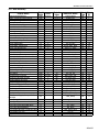
TABLE OF FIGURES
Figure 1: Basic Screen Overview...............................................................................................................9
Figure 2: Standby Screen ........................................................................................................................ 10
Figure 3: Home Screen ............................................................................................................................ 11
Figure 4: Mode Screen............................................................................................................................. 12
Figure 5: Setting Screen .......................................................................................................................... 14
Figure 6: Time Clock Screen.................................................................................................................... 15
Figure 7: Daily Schedule Screen.............................................................................................................. 16
Figure 8: Holiday Schedule Screen.......................................................................................................... 17
Figure 9: Override Schedule Screen ........................................................................................................ 18
Figure 10: 24 Hours a Day 7 Days a Week (24/7) Screen........................................................................ 19
Figure 11: Clock Set Screen.....................................................................................................................20
Figure 12: Status Screen..........................................................................................................................22
Figure 13: Alarm Screen ..........................................................................................................................23
Figure 14: Calibration Screen...................................................................................................................24
Figure 15: Manual Overrides - Technician Use Only................................................................................25
Figure 16: Configuration - Technician Use Only.......................................................................................27
Figure 17: Keypad Screen........................................................................................................................28
Figure 18: MUA/FR with Forced Supply Air Heating ................................................................................29
Figure 19: MUA/FR with Room Air Temperature Control..........................................................................30
Figure 20: MUA/FR with Outdoor Air Room Temperature Control............................................................31
Figure 21: AM/VAV with Forced Supply Air Heating.................................................................................32
Figure 22: AM/VAV with Room Air Temperature Control ..........................................................................33
Figure 23: AM/VAV with Outdoor Air Room Temperature Control ............................................................34
Figure 24: Basic Wiring Diagram Part One ..............................................................................................35
Figure 25: Basic Wiring Diagram Part Two...............................................................................................36
Figure 26: Basic Wiring Diagram Part Three............................................................................................37
Figure 27: RAPID® InfinityPro™ Networking Software .............................................................................38
Figure 28: Control Board..........................................................................................................................39
Figure 29: Getting to Know the Interface..................................................................................................41
Figure 30: Configure ................................................................................................................................41
Figure 31: Download ................................................................................................................................42
Figure 32: Air Handler Network Tree........................................................................................................42
Figure 33: Sensor / Network Cable for InfinityPro ....................................................................................43
Figure 34: Cabling and Network Specifics for Use with One Handler ......................................................44
Figure 35: Cabling and Network Specifics for Use with Multiple Air Handlers .........................................45
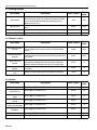
LIST OF TABLES
Table 1: Mode Commands.......................................................................................................................12
Table 2: Setting Commands ....................................................................................................................13
Table 3: Schedules ..................................................................................................................................15
Table 4: Schedule Example .....................................................................................................................16
Table 5: Status Conditions.......................................................................................................................21
Table 6: Alarm Description.......................................................................................................................23
Table 7: Calibration Adjustments .............................................................................................................24
Table 8: Configuration Status ..................................................................................................................26
Table 9: Desktop Computer Requirements..............................................................................................38
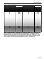
Table 10: Thermistor Performance ..........................................................................................................59
There are references in this manual to various trademarks. All trademarks mentioned herein, whether registered or not, are the property of their respective owners. Rapid Engineering LLC is not sponsored by or affiliated with any of the trademark or registered trademark owners, and makes no representations about them,
their owners, their products or services.
SECTION 1: INTRODUCTION
SECTION 1: INTRODUCTION
This manual is to be used in conjunction with the RAPID® 4000-Series Industrial Air Handler Installation,
Operation and Service Manual (P/N RP140000NA).
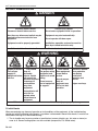
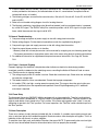
1.1 Safety
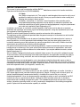
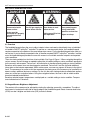
Your Safety is Important to Us! This symbol is used throughout the manual to notify you of
possible fire, electrical or burn hazards. Please pay special attention when reading and
following the warnings in these sections.
Installation, service and, at a minimum, annual inspection of the controller and its
associated heating/cooling equipment must be done by an electrician qualified in the
installation and service of control systems for heating equipment, using only replacement
parts sold and supplied by Rapid Engineering LLC.
Installation, service and, at a minimum, annual inspection of the heater must be done by a contractor
qualified in the installation and service of gas-fired heating equipment, using only replacement parts sold
and supplied by Rapid Engineering LLC.
Read this manual carefully before installation, operation and service of this equipment.
The appliance must be applied and operated under the general concepts of reasonable use and installed
using best building practices.
This appliance is not intended for use by persons (including children) with reduced physical, sensory or
mental capabilities, or lack of experience and knowledge unless they have been given supervision or
instruction concerning use of the appliance by a person responsible for their safety. Children should be
supervised to ensure that they do not play with the appliance.
For optimum heater performance and safe heating conditions, inspect and maintain heater before every
heating season as necessary. Also, know and maintain heater clearances to combustibles, see heater
Installation, Operation and Service Manual for further details. If you require additional manuals, contact
Rapid Engineering LLC.
This air handler is designed for heating non-residential indoor spaces. Do not install in residential spaces.
These instructions, the layout drawing, local codes and ordinances and applicable standards that apply to
gas piping, electrical wiring, ventilation, etc must be thoroughly understood before proceeding with the
installation.
Gas-fired appliances are not designed for use in atmospheres containing flammable vapors or dust or
atmospheres containing chlorinated or halogenated hydrocarbons. Recirculated room air my be hazardous if
containing flammable solids, liquids and gases.; explosive materials; and/or substances which may become
toxic when exposed to heat (i.e. refrigerants, aerosols, etc.)
1.2 What is a RAPID® InfinityPro™ Controller?
The RAPID® InfinityPro™ is a control system for use with a RAPID® 4000-Series air handler. It includes a
DDC (direct digital control) controller containing 8 outputs (5 digital, 3 analog) and 6 universal inputs. An
optional handheld keypad (remote control device) is available to be used on site as a start-up/
troubleshooting device. It may also be permanently mounted to a column or wall, and cabled to the DDC
controller for use as a remote control device. If desired, the DDC controller allows the air handler to
communicate with a building management system. The handheld keypad allows the end user to adjust
settings, schedules, operating modes, as well as receive data independent of the building management
system. Optional off-site communication capability is available.
1 of 61
RAPID® INFINITYPRO™ USER, OPERATION AND SERVICE MANUAL
1.3 Electrical Requirements
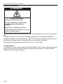
DANGER
Electrical Shock Hazard
Disconnect electric before service.
More than one disconnect switch may be
required to disconnect electric from
equipment.
Equipment must be properly grounded.
Failure to follow these instructions can result
in death or electrical shock.
Failure to comply with the installation instructions will invalidate the limited warranty set out on Page 61, Section 8.
The RAPID® InfinityPro™ must be installed and electrically grounded in accordance with the following:
United States: Refer to National Electrical Code®, NFPA 70 - latest revision. Wiring must conform to the most
current National Electrical Code®, local ordinances and any special diagrams furnished.
Canada: Refer to Canadian Electrical Code, CSA C22.1 Part 1 - latest revision.
1.4 Communication
The InfinityPro™ has built-in protocol support for BACnet®, Modbus and N2. Lonworks open communication
protocol is also available as an option. Front-end air handling system software is available from Rapid
Engineering LLC. See Page 38, Section 5.
2 of 61
SECTION 2: SEQUENCE OF OPERATION
SECTION 2: SEQUENCE OF OPERATION
DANGER
Electrical Shock Hazard
Disconnect electric before service.
More than one disconnect switch may be
required to disconnect electric from
equipment.
Equipment must be properly grounded.
WARNING
Carbon Monoxide Hazard
Do not recirculate air from the heated space
over burner.
Air supply to burner must be from outside.
Failure to follow these instructions can result
in death or injury.
Failure to follow these instructions can result
in death or electrical shock.
2.1 Air Handler Model Configurations
Based on the air handler application, the air handler may be configured in any of the four models described
in the upcoming sections.
2.1.1 Air Management (AM)
The air handler provides a variable outside air / return air ratio within the range of 100% outdoor air / 0%
return air to 20% outdoor air / 80% return air during the heating seasons, and up to 100% return air during
the cooling season. The unit controls the amount of outdoor air delivered into the building by modulating outdoor air and return air dampers. Supply air volume is fixed.
2.1.2 Variable Air Volume (VAV)
The air handler provides 100% outdoor air with a variable supply air volume from 20% - 100% with use of
bypass section. This air handler has no return air capabilities. The unit controls the amount of outdoor air
delivered into the building by modulating dampers.
2.1.3 Make-Up Air (MUA)
The air handler provides a fixed supply air volume of 100% outdoor air to a building. This air handler has no
return air capabilities. An optional variable frequency drive is available to modulate the total air volume when
desired.
2.1.4 Fixed Recirculation (FR)
The air handler provides a fixed 20% outdoor air and 80% return air to a building. Supply air volume is fixed
in both heating and cooling seasons.
2.2 Select Operating Modes
Each air handler is capable of operating in one of three different modes: Off, On or Auto mode can be
selected. Flush mode is also available but forced via building sensor, such as carbon dioxide or carbon monoxide. Setting commands (See Page 13, Table 2) or status conditions (See Page 21, Table 5) can be viewed
via front-end software available from Rapid Engineering LLC or handheld keypad (if connected). See Page
38, Section 5 for additional information on Rapid Engineering LLC provided front-end software.
3 of 61
RAPID® INFINITYPRO™ USER, OPERATION AND SERVICE MANUAL
2.2.1 Off
In this mode of operation, the fan and burner are off and all outdoor air dampers are closed. The air handler
continues to report status conditions and other settings based on operating conditions.
2.2.2 On
In this mode of operation, the Time Clock / Schedule is not in use. The fan runs continuously, the available
heating and cooling functions respond to maintain their occupied settings.
2.2.3 Auto
In this mode of operation, the air handler is controlled by the Time Clock. During occupied periods, the fan
runs continuously. Heating and cooling functions respond as needed to maintain their respective settings.
During unoccupied periods, the fan and heat will both cycle on and off as needed to maintain the unoccupied
setback temperature setting. Any available cooling functions are not active during unoccupied time periods.
2.3 Outdoor Air Control
Reference RAPID® 4000-Series Industrial Air Handler Installation, Operation and Service Manual
(RP140000NA) Installer Responsibility section for building pressure damper relief information.
• Installer is responsible to provide building pressure relief/damper fans to prevent over pressurization of a
building, if needed.
2.3.1 Manual Percent Outdoor Air
This is applicable only to Air Management and Variable Air Volume model configuration. Whenever the fan is
operating, the mixing dampers are fixed at the Manual Air setting.
2.3.2 Auto Room Pressure
This is applicable only to Air Management and Variable Air Volume model configuration. A pressure transducer compares the pressure inside the building to the pressure outside the building or can be used to compare pressure from a particular room to an adjacent room. Whenever the fan is operating, the dampers are
automatically positioned to maintain the Auto Room Pressure setting, except during the following conditions:
1. Economizer is active. (See Page 6, Section 2.8.1)
2. Evaporative Cooling is operating. (See Page 6, Section 2.8.2)
3. Flush mode is activated. (See Page 4, Section 2.4)
2.4 Flush Mode
Flush mode provides 100% outdoor air to the building space. It is applicable to many model configuration
styles: Air Management, Variable Air Volume and Make-Up Air. Even if the air handler is in the unoccupied
period or Off mode, the fan will start when Flush mode is triggered. The temperature controls respond as
needed to maintain the heating and cooling set points. This forced fresh air condition overrides both Manual
Percent Outdoor Air (See Page 4, Section 2.3.1) and Auto Room Pressure (See Page 4, Section 2.3.2)
damper operations.
2.5 Heating Control Type Occupied Period
During an occupied period, the fan runs continuously and heat is provided. There are three different types of
heating controls available: Room Air Temperature Control, Force Supply Air Heating and Outdoor Air Room
Control. When changing a temperature heating type control, careful consideration should be taken.
4 of 61
SECTION 2: SEQUENCE OF OPERATION
2.5.1 Room Air Temperature Control
• The heating setting is activated if the room temperature falls below the Occupied Heating setting. The
heat is dynamically modulated to maintain the supply air temperature between the minimum and maximum supply air temperature settings as needed to maintain the Occupied Heating setting.
• If the room temperature continues to increase reaching the Heat Off Setting, the heat is deactivated. The
heat will remain off until the room temperature drops below Occupied Heating setting.
2.5.2 Forced Supply Air Heating
• If the room temperature drops below the Occupied Heating Setting, the heat will start and modulate as
needed to maintain the Forced Supply Air Heating setting.
• If the room temperature continues to increase reaching the Heat Off Setting, the heat is deactivated. The
heat will remain off until the room temperature drops below the Occupied Heating setting.
2.5.3 Outdoor Air Room Control
• If the outdoor air temperature drops below the Outdoor Air Heat On setting, the heating function is activated.
• When the heat is on, the supply air temperature is controlled as detailed on Page 5, Section 2.5.1 - Room
Temperature Control.
• The heat will shut off when the outdoor air temperature is above the Heat Off If Outdoor Air Above setting.
2.5.4 Heating Function Notes
• The heat is disabled if the outdoor air temperature is greater than the Heat Off If Outdoor Air Above setting for all of the temperature controls listed above. The factory default setting is 95 °F. This function is
available in all three heating types as described on Page 5, Section 2.5.1 through Page 5, Section 2.5.3.
• If the heat fails and the supply air temperature drops below the Fan Off If Supply Air Temp Below setting,
the fan will shut off and generate an alarm (See Page 23, Section 3.9).
• The fan and heat operation are disabled in the unoccupied period.
2.6 Heating Mode Unoccupied Setback
During an unoccupied setback period, the fan and heat will only run when the room temperature falls below
the Unoccupied Setback Temp setting. Cooling is disabled during unoccupied periods.
2.6.1 Room Air Temperature Control & Forced Supply Air Heating
If the room temperature falls below the Unoccupied Setback Temp setting, the fan and heat will start. The
heat will remain on until the room temperature reaches the Heat Off Setting.
2.6.2 Outdoor Air Room Control
When this function is selected, the fan and heat operation are disabled in the unoccupied period.
2.7 Heating Types
2.7.1 Direct Fired Gas Burner
The burner is controlled by an analog output from the RAPID® InfinityPro™ controller and will operate as
described in Heating Mode occupied period on Page 4, Section 2.5 through Page 5, Section 2.6.
5 of 61
RAPID® INFINITYPRO™ USER, OPERATION AND SERVICE MANUAL
2.7.2 Electric, Hot Water or Steam Coils
Heat output modulation of the coils is performed via an analog output from the RAPID® InfinityPro™ controller. Upon a call for heat, fan operation is delayed for 60 seconds to allow for coil warm up. When in the heating mode, the controller will modulate the heating coil as described on Page 4, Section 2.5 through Page 5,
Section 2.6. For electric, hot water or steam as a heat source, configure the controller as per Page 26, Section 3.12.
2.8 Cooling Types
RAPID® InfinityPro™ controller provides a single output for cooling control. The cooling output activates an
evaporative cooling module or mechanical cooling coil (initiation only). For multiple stages of mechanical
cooling, consult the factory.
2.8.1 Economizer (AM & VAV Models)
The Economizer is a selectable feature and must be selected ON with the settings screen (See Page 13,
Section 3.6) in order to function. Outdoor air for cooling is used when the outdoor air temperature is below a
user-specified value for the Economizer Setting. Whenever the outdoor air temperature is above the Economizer Setting, the air handler will operate with the amount of outdoor air determined by the Outdoor Air Control setting.
When selected, the Economizer functions as if there is no call for heat. A condition in which there is no call
for heat is if the outdoor air temperature falls below the Economizer Setting and the room air temperature is
above the Cooling Setting. If all of these conditions are met, the Economizer control brings in up to 100% outdoor air to maintain the Cooling Setting. When the room air temperature falls below the Cooling setting, the
air handler will resume damper modulation determined by the Outdoor Air Control setting.
While bringing in additional outdoor air for cooling, the room pressure may rise above the Room Pressure
Setting. To minimize the potential for an excessively high building pressure, relief dampers can be installed.
During Economizer operation, if the supply air temperature falls below the Supply Air Min Temp setting, the
dampers will modulate to maintain the Supply Air Min Temp setting.
2.8.2 Evaporative Cooling
Evaporative Cooling overrides the Economizer control. The dampers are forced to 100% outside air on AM &
VAV models when the room temperature rises above the Cooling Setting. A digital output from the controller
will enable the Evaporative Cooler. When the Cooling Setting is satisfied, the air handler will resume damper
modulation based on the previously selected Auto Room Pressure or Manual Percent Outside Air setting.
While bringing in additional outdoor air during evaporative cooling operation, the room pressure may rise
above the Auto Room Pressure setting. To minimize the potential for an excessively high building pressure,
relief dampers can be installed in the space.
2.8.3 Mechanical Cooling
The 20% burner supply air damper on Air Management and Variable Air Volume models is closed at all times
during the cooling operation with the exception of Evaporative Cooling. Mechanical Cooling is available in
both Auto Room Pressure and Manual Percent Outside Air setting.
2.8.4 Time Clock
The air handler can be controlled by more than one schedule, but not at the same time. The schedule source
must be selected by the operator. Selecting the schedule source is accomplished via the configuration
screen (See Page 26, Section 3.12) using the handheld keypad, a building management (automation) system or WebCTRL software. See Page 8, Section 3 for more information on keypad screens and Page 15,
Table 3 for schedule options.
6 of 61
SECTION 2: SEQUENCE OF OPERATION
2.9 Options
2.9.1 Energy Alert Control (AM &VAV Models)
This control function is only active during occupied periods and when the air hander is in the Auto Room
Pressure setting. When activated, this control function monitors the room pressure. If for any reason the room
pressure remains 0.01" w.c. below the Auto Room Pressure setting for ten consecutive minutes, the energy
alert control reverts back to the Unoccupied Setback Temp setting. The dampers are then forced to the minimum outside air position (20% outdoor air / 80% return air). This condition will be maintained for 20 minutes
or until the room under pressure condition has been corrected. Once either of these events occur, the Occupied Heating setting is restored and modulation of the dampers is returned to Auto Room Pressure control.
NOTE: Each time the energy alert control reverts to the Unoccupied Setback Temp, an alarm is activated to
alert low building pressure.
2.9.2 Make Up Air Units with Variable Frequency Drive
When a variable frequency drive is installed on a make-up air unit, the fan modulates between the minimum
and maximum air delivery capacity of the air handler vs. the Auto Room Pressure setting to control building
pressure. Auto Room Pressure setting can be adjusted within the setting screen (See Page 13, Section 3.6)
with the handheld keypad or by using head end software (See Page 38, Section 5). Burner air velocity is
controlled by a profile damper. A pressure transducer compares static building pressure to the static pressure outdoors, or to the pressure in another part of the building.
2.9.3 Forced Occupied
When the air handler is equipped with a room sensor (RS Plus or RS Pro), the unit can be forced to occupied
mode by pushing the "manual on" button located on the face of the room sensor. Each time this button is
pushed, it adds 30 minutes to occupied period, up to a total of four hours. Holding the "manual on" button in
for three seconds cancels the Forced Occupied period.
7 of 61
RAPID® INFINITYPRO™ USER, OPERATION AND SERVICE MANUAL
SECTION 3: USER INSTRUCTIONS
WARNING
DANGER
Electrical Shock Hazard
Disconnect electric
before service.
Explosion Hazard
Turn off gas supply to
heater before service.
Heater must be
connected to a properly
grounded electrical
source.
Burn Hazard
Allow heater to cool
before service.
Cut/Pinch Hazard
Wear protective gear
during installation,
operation and service.
Tubing may still be hot
Edges are sharp.
after operation.
Failure to follow these instructions can result in death, electric shock, injury or property damage.
3.1 Overview
The handheld keypad allows the user to adjust setpoint values and receive data directly from an individual
air handler's RAPID® InfinityPro™ controller. To operate as a remote control device, the handheld keypad
requires connection to the bottom of the room temperature sensor. For the handheld keypad to be used as a
service tool, it can be directly connected to the air handler mounted RAPID® InfinityPro™ controller. In either
case, the handheld keypad provides the user with access to all available controller setpoints and reported
status conditions.
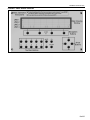
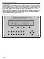
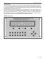
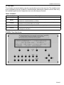
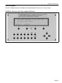
The main viewing window has four lines of text available. See Page 9, Figure 1. When navigating through the
various screens, text will change as needed to reflect the air handler settings or status conditions appropriate
for the currently active screen. Text on line 1 will indicate the air handler operating setting or status condition.
Based on active screen, items can be changed or monitored. Text on line 2 and line 3 provide additional
information on the features represented. Within active screen, an arrow may appear all the way to the right of
line 3. The presence of an arrow on this line represents the viewing area of the screen may be scrolled up or
down to access additional features or settings. On line 4 in the main viewing window, bracketed text appears
above any of the four navigation buttons. Using the navigation buttons, the user is able to switch screens
based on selected bracketed text.
Based on selected screen, temperatures are displayed as a variable setting or status condition. Temperatures indicated are in Fahrenheit.
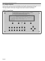
3.2 Keypad Screen Brightness Adjustment
The contrast of the screen can be adjusted by rotating the adjusting screw with a screwdriver. The adjustment screw is located on the left side of the top edge of the handheld keypad. Rotate it counter clock-wise
(CCW) to make it brighter and clock-wise (CW) to make it dimmer.
8 of 61
SECTION 3: USER INSTRUCTIONS
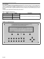
FIGURE 1: Basic Screen Overview
9 of 61
RAPID® INFINITYPRO™ USER, OPERATION AND SERVICE MANUAL
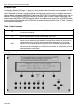
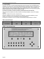
3.3 Standby Screen
When the handheld keypad is connected to the DDC Controller, the first screen to appear will be the Standby
Screen. See Page 10, Figure 2. User will be able to easily identify room temperature and fan status based on
information shown in main viewing window on line 3. For convenience, date and time are also shown on line
2. Within standby screen parameters, information is fixed (room temperature and fan status). In order to
implement changes, push any key and follow directions based on subsequent screens.
If inactivity takes place for one minute, this screen will be displayed. This is the factory default setting. User
can change inactivity time duration in the Configuration Screen. A special button sequence is required to
access the Configuration Screen. See Page 26, Section 3.12.
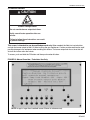
FIGURE 2: Standby Screen
10 of 61
SECTION 3: USER INSTRUCTIONS
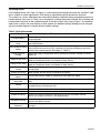
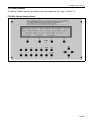
3.4 Home Screen
On the Home Screen (See Page 11, Figure 3) the user can easily identify heat/cool settings, room temperature, fan status and mode of operation. Within screen parameters, information is fixed (room temperature, fan
status and mode of operation). In order to implement changes, advance to appropriate primary screen based
on desired changes. See Page 29, Section 3.13.
From the Home Screen, the user can navigate to each subsequent primary screen (Mode, Settings, Status
and Alarm). The navigation buttons under the bracketed corresponding text, once selected, advance user to
the next screen. Screen advances are [➝ Mode], [➝ Settings], [➝ Status], or [➝ Alarm]. For Mode information, See Page 12, Section 3.5. For Setting information, See Page 13, Section 3.6. For Status information, See Page 21, Section 3.8. For Alarm information, See Page 23, Section 3.9.
FIGURE 3: Home Screen
11 of 61
RAPID® INFINITYPRO™ USER, OPERATION AND SERVICE MANUAL
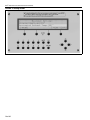
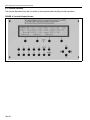
3.5 Mode Screen
On the Mode Screen (See Page 12, Figure 4), the air handler mode of operation can be selected. ON, OFF
and AUTO are the three modes available. On line 3, bracketed text represents mode of operation selected
and is adjustable by the user. In order to change operating mode, use arrow keys to navigate around main
viewing window and enclose ON/OFF/AUTO text. Once ON/OFF/AUTO is properly bracketed, press enter on
keypad. The text [OK][CANCEL][DECR] and [INCR] will then appear in line 4. Using a combination of the
arrow buttons and [INCR] or [DECR] navigation buttons, the mode can be altered. Use the [CANCEL] button
to terminate the command and use the [OK] button to accept the command. See Page 12, Table 1 for operation modes with descriptions.
Table 1: Mode Commands
Mode of Operation
Description
OFF
The fan and heat will not run unless overridden by flush or forced occupied command. The
air handler is turned off.
ON
The fan runs continuously, the available heating and cooling functions respond to maintain
their occupied settings. The time clock/schedule is not in use.
AUTO
The fan will run continuously in the occupied period and turns off in the unoccupied period
unless the room temperature falls below the unoccupied heat setting. The heat cycles on
and off based on the heat setting. During scheduled occupied periods, the air handler
operates in the occupied sequence of operation. During scheduled unoccupied periods,
the air handler operates in the unoccupied sequence of operation. The air handler operates based on the scheduling that is entered into the controller, or as directed by the handheld keypad, web control or BAS.
FIGURE 4: Mode Screen
12 of 61
SECTION 3: USER INSTRUCTIONS
3.6 Setting Screen
On the Setting Screen (See Page 14, Figure 5), various heating and cooling commands are available in addition to outdoor air control adjustments. Each setting is adjustable based on desired user operation.
This screen has a show / hide feature that automatically displays applicable setting commands based on air
handler features. See Page 13, Table 2 for a complete list of setting commands available. Not all settings will
be displayed at one time on the handheld keypad. At the end of line 3 (See Page 9, Figure 1 for reference),
when arrow is visible, use arrow buttons to scroll up/down for additional settings. Settings can be changed
with the handheld keypad via number buttons to define settings.
Table 2: Setting Commands
Setting
Description of Temperature and Outdoor Air Settings
Occupied Heating
This setting is used to specify the desired room temperature that is maintained during
occupied periods.
Unoccupied Setback
Temp
This setting is used to specify the desired room temperature that is maintained during
unoccupied periods.
Heat Off Above Heating
Setting
Forced Supply Air
Heating
This setting is added to the Occupied and Unoccupied heat setting to define the temperature at which the heat turns off. This is referred to as the Heat Off Setting on the Status
screen of the handheld keypad. (See Page 21, Table 5).
Defines the supply air temperature when the temperature controls selected are Forced
Supply Air.
Supply Air Min Temp
Defines the supply air minimum temperature when temperature controls selected are
Room Air Temperature Control and Outdoor Air Room Control.
Supply Air Max Temp
Defines the supply air maximum temperature when the temperature controls selected are
Room Air Temperature Control and Outdoor Air Room Control.
Supply Air Max Temp
Locked
This setting is displayed when the unit is configured with a 30 °F plus heat setting lock. It is
not adjustable.
Outdoor Air Heat On
When enabled, the heat will turn on based on this setting.
Heat Off If Outdoor Air
Above
The heat will shut off if outdoor air temperature raises above this setting.
Fan Off If Supply Air
Temp Below
The fan will shut down if supply air temperature falls below this setting for more than 5 minutes.
Cooling
The setting that starts the cooling sequence, if available. The cooling set point cannot be
set below Heating Off Setting plus one.
Economizer
Enables or disables the Economizer by turning it ON or OFF.
Economizer Setting
Defines the maximum outdoor temperature allowed for Economizer cooling.
Outdoor Air Control
Pressure: the dampers modulate automatically to maintain Auto Room Pressure.
Manual: the dampers are fixed at a user defined setting.
Auto Room Pressure
Defines the setting when Pressure is selected. The dampers modulate automatically to
maintain Auto Room Pressure.
Manual Percent
Outdoor Air
Defines the setting when Manual is selected. The dampers remain fixed until the setting is
changed.
13 of 61
RAPID® INFINITYPRO™ USER, OPERATION AND SERVICE MANUAL
FIGURE 5: Setting Screen
14 of 61
SECTION 3: USER INSTRUCTIONS
3.7 Time Clock
The air handler can be controlled by more than one schedule, but not at the same time. The schedule source
must be selected by the user; the default is handheld keypad. Selecting the schedule source is done using
the handheld keypad from the Configuration menu or by the 3rd party front end.
Table 3: Schedules
Schedule Options
Daily
Description
Typical daily schedule defined by normal occupied period.
Holiday
The Holiday schedule forces the air handler to the unoccupied mode overriding the daily
schedule for all periods defined as a Holiday.
Override
The Override schedule forces the air handler to the occupied mode overriding all other
schedules for the periods defined as Override.
24/7
Clockset
Forces the air handler to occupied mode 24 hours a day, 7 days a week.
Use this feature to update the time and date of the air handler controller to which the handheld keypad is connected.
FIGURE 6: Time Clock Screen
15 of 61
RAPID® INFINITYPRO™ USER, OPERATION AND SERVICE MANUAL
3.7.1 Daily Schedule
Using the arrow buttons, move the brackets between the start and stop times. Press the ENTER button to
change the start and stop times. The text [OK] [CANCEL] [DECR] and [INCR] will appear at the bottom of the
screen. Change the values to the desired settings. Next, using the arrow buttons, move the brackets and
select the days you want the air handler to operate. Press the ENTER button and use the [DECR] & [INCR]
to hide or show the days. Press the [OK] to accept the change.
To activate the schedule, it must be turned on by selecting YES next to the word Use.
There are three daily schedules, two holiday schedules, two override schedules, and one 24/7 schedule
available.
Operation is limited to 24-hour clock, astronomical time.
Each day's schedule may not be set to stop later than 23:59 PM. If you want the schedule to run past
midnight, two schedules must be established to cover the occupied period.
An example of a schedule to run from 7:00 AM to 2:00 AM Monday through Saturday is as follows:
Table 4: Schedule Example
Example
Start
Stop
Days
Daily Schedule 1
07:00
23:59
-MTWTF-
Daily Schedule 2
00:00
02:00
--TWTFS
FIGURE 7: Daily Schedule Screen
16 of 61
SECTION 3: USER INSTRUCTIONS
3.7.2 Holiday Schedule
The holiday schedule forces the air handler to the unoccupied mode. See Page 5, Section 2.6.
FIGURE 8: Holiday Schedule Screen
17 of 61
RAPID® INFINITYPRO™ USER, OPERATION AND SERVICE MANUAL
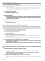
3.7.3 Override Schedule
The Override Schedule forces the air handler to the occupied mode overriding all other schedules.
FIGURE 9: Override Schedule Screen
18 of 61
SECTION 3: USER INSTRUCTIONS
3.7.4 24/7 Schedule
The 24/7 schedule forces the air handler into occupied mode 24 hours a day, 7 days a week.
FIGURE 10: 24 Hours a Day 7 Days a Week (24/7) Screen
19 of 61
RAPID® INFINITYPRO™ USER, OPERATION AND SERVICE MANUAL
3.7.5 Clock Set
To change the time and date, use the arrow buttons to move the brackets over the desired time or date. Push
the ENTER button then use the [DECR] or [INCR] buttons at the bottom of the display to make the change.
Push the ENTER or [OK] button to accept the change.
Pushing the DST button will enable the operator to shift the controller to daylight savings time.
FIGURE 11: Clock Set Screen
20 of 61
SECTION 3: USER INSTRUCTIONS
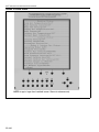
3.8 Status Screen
On the Status Screen (See Page 22, Figure 12), users are able to view all current conditions with heating,
cooling and outdoor air status. Within screen parameters, results displayed are fixed. In order to change air
handler status, advance to appropriate setting screen based on desired changes.
This screen has a show / hide feature that automatically displays applicable status conditions. See Page 21,
Table 5 for a complete list of status conditions available. Depending on the model and features of the air handler, not all status conditions will be displayed at one time on the handheld keypad. At the end of line 3, when
arrow is visible, use arrow buttons to scroll up/down for additional status options.
Table 5: Status Conditions
Status
Room Air Temperature
Heat Setting Current
Heat Off Setting
Supply Air Temperature
Heat Status
Outdoor Air Temperature
Percent Heat Output
Description
Displays current room temperature
Displays current heat setting for either occupied or unoccupied period determined by time clock
Displays current heat off setting for either occupied or unoccupied period
Displays current supply air temperature
Displays if the heat is ON or OFF
Displays current outdoor air temperature
Displays the current output percent to the heat source
Cooling Setting
Displays the current cooling setting
Cooling Output
Displays if the cooling output is ON or OFF
Economizer Active
Displays if the economizer is active by YES or NO
Operating Mode
Displays the current mode of operation: ON, OFF, AUTO or FLUSH
Occupied Period
Displays YES if occupied and NO if unoccupied
Outdoor Air Control
Room Pressure
Displays current outdoor air control: Pressure or Manual
Displays current room pressure
Room Pressure Setting
Displays current setting for room pressure
Percent Outdoor Air
Displays the current percent of outdoor air
Percent Outdoor Air Setting
Percent Output to VFD
Displays the current manual outdoor air setting
Displays current output to variable frequency drive
Schedule Source
Displays the schedule source: Handheld keypad, BAS or WebCTRL
Air Handler Type
Displays the air handler type: MUA, VAV, AM, FR
21 of 61
RAPID® INFINITYPRO™ USER, OPERATION AND SERVICE MANUAL
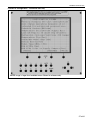
FIGURE 12: Status Screen
NOTE: Image is larger than handheld screen. Shown for reference only.
22 of 61
SECTION 3: USER INSTRUCTIONS
3.9 Alarm
When an alarm is triggered, the red alarm light will illuminate on the handheld keypad. To clear the alarm
light, the fault must be corrected. The alarm screen stores the last 100 alarms. Alarms are time stamped and
stored in RTN. RTN or "Return to Normal" is part of the alarm screen and can be viewed if scrolled down. If
alarm is reset, it is not stored in RTN. (To reset alarm see information below)
Alarms run newest to oldest within alarm screen. Real time run info is available in the status screen. See
Page 21, Section 3.8.
To reset the alarm light, push and hold the FN button then push MUTE.
Table 6: Alarm Description
Description of Alarm
Reference
Fan Contactor Not On
See Page 52, Section 7.3.1
Fan Contactor On When Should Be Off
See Page 52, Section 7.3.2
Damper for Heat Air Not Open.
See Page 52, Section 7.3.3
Damper for Heat Air Not Closed
See Page 53, Section 7.3.4
Burner Lockout or Safety SW Not Made
See Page 53, Section 7.3.5
Low Supply Air Temp Shutdown
See Page 56, Section 7.3.6
Dirty Filters
See Page 57, Section 7.3.7
Low Building Pressure
See Page 58, Section 7.3.8
FIGURE 13: Alarm Screen
23 of 61
RAPID® INFINITYPRO™ USER, OPERATION AND SERVICE MANUAL
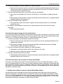
3.10 Calibration
This screen should be used by qualified personal only. The Calibration Screen is used to calibrate input
sensors, if needed. Move the brackets around the number for the sensor to be calibrated, press ENTER, and
then use the arrow buttons or [DECR] and [INCR] to increase or decrease. Press ENTER or [OK] to save the
changes.
To access, push and hold the FN button then push number 7.
Table 7: Calibration Adjustments
Text
Status
Build Press Offset
00.0
Room Temp Offset
00.0
OA Temp Offset
00.0
DA Temp Offset
00.0
NOTE: OA=Outside Air; DA=Discharge Air
FIGURE 14: Calibration Screen
24 of 61
Description
Increase or decrease the offset to change the actual reading
SECTION 3: USER INSTRUCTIONS
3.11 Manual Overrides
CAUTION
Product Damage Hazard
Do not override burner output lock timer.
Verify normal heater operation after one
minute.
Failure to follow these instructions can result
in product damage.
This screen is intended for use by qualified personal only. When needed, the field start up technician
can lock the burner output to 100% in order to set up the gas fired burner. Caution must be exercised to avoid
possible damage to the equipment when enabling this feature. The burner output lock has a timer that will
shut off this feature after one minute.
To access, push and hold the FN button and then push number 8 button.
FIGURE 15: Manual Overrides - Technician Use Only
NOTE: Image is larger than handheld screen. Shown for reference only.
25 of 61
RAPID® INFINITYPRO™ USER, OPERATION AND SERVICE MANUAL
3.12 Configuration
This screen (See Page 27, Figure 16) is used to configure the air handler for specific options. The controls
are pre-configured from the factory prior to shipping. The default schedule source is handheld keypad. If the
time clock is controlled by a BAS (See Page 46, Section 6) or Webctrl software (See Page 38, Section 5) it
may need to change in the field.
To access, push and hold the FN button and then push number 9.
Table 8: Configuration Status
Text
Status
Description
Schedule Source
Handheld keypad /
BAS / WebCTRL
Selects the schedule source: Handheld keypad, BAS (building
automation system) or WebCtrl can be used for factory provided
software.
Temperature Ctrl
Room Temp Ctrl
OA Rm Temp Ctrl
Forced Supply Air
See Page 4, Section 2.5.
Lock DA Temp to 30 above
Htg SP
On / Off
Locks the supply air maximum temp to 30 °F above the heating
setting
Mech Cooling
No / Yes
Select Yes if the unit has mechanical cooling. The 20% burner
supply air damper will close when in the cooling mode
Evaporative Clg
No / Yes
Select Yes if unit equipped with evaporative cooling
Coil Heat Source
No / Yes
Select Yes if the heat source is steam, hot water or electric
Energy Alert
No / Yes
Select Yes to enable feature, See Page 7, Section 2.9.1.
Model Type
AM/VAV or MUA/FR
Defines the model of the air handler and the features available
MUA W/VFD
No / Yes
Select Yes if the air handler is an MUA with a factory installed
variable frequency drive.
MUA W/No Inlet or Supply
Damper
No / Yes
Select Yes if the air handler is an MUA with no inlet or supply air
damper
26 of 61
SECTION 3: USER INSTRUCTIONS
FIGURE 16: Configuration - Technician Use Only
NOTE: Image is larger than handheld screen. Shown for reference only.
27 of 61
RAPID® INFINITYPRO™ USER, OPERATION AND SERVICE MANUAL
3.12.1 Keypad Configuration
From this screen, inactivity timeout can be adjusted. Increasing the inactivity timeout will delay the amount of
time before the screen reverts back to the Standby Screen when the handheld keypad sits idle.
The range available is 1-255 minutes. Changes can be made via number or arrow buttons.
FIGURE 17: Keypad Screen
28 of 61
SECTION 3: USER INSTRUCTIONS
Screens
Primary
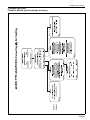
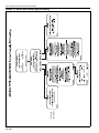
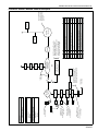
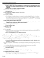
3.13 Model Flow Charts
FIGURE 18: MUA/FR with Forced Supply Air Heating
29 of 61
RAPID® INFINITYPRO™ USER, OPERATION AND SERVICE MANUAL
30 of 61
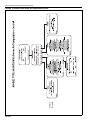
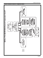
Screens
Primary
FIGURE 19: MUA/FR with Room Air Temperature Control
SECTION 3: USER INSTRUCTIONS
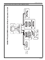
Screens
Primary
FIGURE 20: MUA/FR with Outdoor Air Room Temperature Control
31 of 61
RAPID® INFINITYPRO™ USER, OPERATION AND SERVICE MANUAL
32 of 61
Screens
Primary
FIGURE 21: AM/VAV with Forced Supply Air Heating
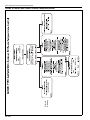
SECTION 3: USER INSTRUCTIONS
Screens
Primary
FIGURE 22: AM/VAV with Room Air Temperature Control
33 of 61
RAPID® INFINITYPRO™ USER, OPERATION AND SERVICE MANUAL
34 of 61
Screens
Primary
FIGURE 23: AM/VAV with Outdoor Air Room Temperature Control
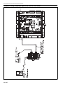
SECTION 4: WIRING
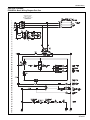
SECTION 4: WIRING
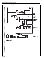
FIGURE 24: Basic Wiring Diagram Part One
FEEDER PROTECTION
SIZING BY OTHERS.
REF: N.E.C. TABLE 430–152
POWER SUPPLY
208/230/460/575 VOLT
102
101
84
2
1
21
22
8
9
24
10
19
14
5
18
15
16
30
31
32
33
34
18
2
35 of 61
RAPID® INFINITYPRO™ USER, OPERATION AND SERVICE MANUAL
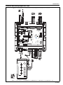
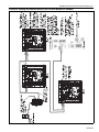
FIGURE 25: Basic Wiring Diagram Part Two
18
34
40
35
41
43
44
45
46
49
63
61
20
1
64
65
66
36 of 61
2
108
88FO
E143900
TYPE: 002206
R
Open Energy
Management Equipment
3
8
7
6
9
4
0
5
MUTE
24 Vac, 50-60 Hz
8.4VA, 0.35A
12Vdc, 0.2A, 2.4W
ENTER
FN
Rnet +
Gnd
G/BK
2
Rnet -
WHT
Rnet -
BLU
CR
Gnd
Gnd
IN-5
IN-6
83
84
85
86
LED
IN-4
82
Gnd
IN-3
Gnd
IN-2
On
On
On
Off
On
R
BACnet
MS/TP
Off
On
Off
TYPE: 002102
N2
Modbus
Open Energy
Management Equipment
88FO
E143900
Off
38.4 K
76.8 K
To Reduce The Risk of Fire
or Electric Shock, Do Not
Interconnect the Outputs of
Different Class 2 Circuits.
CAUTION:
Inputs 5 & 6
Therm, dry, or LStat
Class 2
24Vac, 50-60 Hz
20VA, 0.83A
Use Copper
Conductors Only
Inputs 3 & 4
Therm or dry
Off
9600
19.2 K
Off
BACnet
Power for D.O.s
Outputs
24V Max,
1A Max
Off
On
®
BUS
DO-1
DO-2
DO-3
DO-4
DO-5
AO: 0-10 Vdc
5mA Max
AO-1
Gnd
AO-2
Gnd
Off
Gnd
Gnd
IN-8
IN-7
+3V
Gnd
1
2
3
On
4
Pot.
Only
IN-1
BACnet
over ARC156
EIA-485
IN-2
IN-1
Error
Run
65
Inputs 1 & 2
0-5V, therm, or dry
Access
Local
Gnd
Rnet+
Rnet-
+12V
Sense
2032
+
24V ac
Hot
Power
Gnd
Rnet
LStat
IN-5
LStat
Format
Short pins
66
9
0
1
-
Batt
Tx
Rx
AO-3
Rnet -
Rnet +
Gnd
3 2
7 8
Rnet
+12V
+12V
Rnet +
WHT
RED
Gnd
G/BK
6
5
4
3 2
9
0
1
Shield
SHD
7 8
Net -
net-
6
5
4
Net +
net+
BT485
Comm
Tens
Ones
ALARM
+12V
RED
BLU
1
109
24VAC
90
24
10
9
8
61
63
22
21
93
82
92
81
91
24
21
SECTION 4: WIRING
FIGURE 26: Basic Wiring Diagram Part Three
37 of 61
RAPID® INFINITYPRO™ USER, OPERATION AND SERVICE MANUAL
SECTION 5: WEB CONTROL SOFTWARE FRONT-END COMMUNICATION
5.1 General Information
Rapid Engineering LLC supplied optional networking software is available to allow the user to visually connect with and operate each air handler for proper operation and troubleshooting.
5.2 System Requirements
Web Control desktop computers should have at least a dual core processor, 1.5 GB RAM and a
communication link of 10 Mbps or higher. It will work on slower computer with slower links, but results may
vary. For desktop browser requirements, see Page 38, Table 9. For tablet requirements, consult factory.
Table 9: Desktop Computer Requirements
Computer with this operating system
Windows®
Web Browser
Google™ Chrome™ v23.0 or later
Internet Explorer® v8, v9, v10, or v11 Desktop
Mozilla® Firefox® v21.0 or later
Linux®
Google™ Chrome™ v23.0 or later
Mozilla® Firefox® v21.0 or later
Mac® OS X® (Apple® Mac only)
Safari® v6 or later
Google™ Chrome™ v23.0 or later
Mozilla® Firefox® v21.0 or later
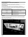
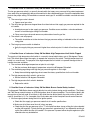
5.3 Graphics
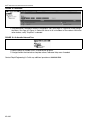
Visual graphic screens help the user to change parameters with ease. An example of the main graphics
screen is shown on Page 38, Figure 27 below. See Page 43, Figure 33 for sensor / network cabling and
Page 45, Figure 35 for networking specifics.
FIGURE 27: RAPID® InfinityPro™ Networking Software
38 of 61
SECTION 5: WEB CONTROL SOFTWARE FRONT-END COMMUNICATION
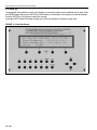
5.4 Setting Up Communication
a. Install the specified network cable to each air handler and router in the network. Connect the
router and computer as shown in drawings on Page 43, Figure 33 through Page 45, Figure 35.
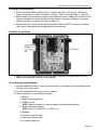
b. Set the address on the controllers using the rotary address switches. Address can be set from 1-99
and must be different for each controller on each network. Cycle power if address is changed
while the controller is powered. See Page 39, Figure 28.
c. Set the baud rate to 76.8 and communication protocol to BACnet MS/TP using the dip switches.
Cycle power if dip switches are changed during normal operation.
FIGURE 28: Control Board
d. Ensure router is powered with power supply provided. The router was downloaded with the IP
address provided by the customer prior to shipping.
5.5 Installing Web Control Software
a. Load CD labeled "Data Base / License" and copy license on to desktop. Once completed, remove
CD from driver and set aside.
b. Load CD labeled WebCTRL and start to run software.
c. Follow instructions on screen during installation
I. Welcome
II. Accept License Agreement
III. Product License
NOTE: Browse for license as saved on desktop and select appropriate file.
IV. Select Destination Directory
NOTE: Default: C://WebCTRL_for_OEMs_6.0
V. WebApps
VI. Network Diagnostic Utility
VII. Select Start Menu Folder
VIII. Installation Summary
39 of 61
RAPID® INFINITYPRO™ USER, OPERATION AND SERVICE MANUAL
5.6 Software Installation Complete (Run)
a. Once the software is loaded, a folder is created on the hard drive named "WebCTRL for OEMs."
Within this folder, locate the "webroot" folder.
b. Re-insert the CD labeled "Data Base / License" and copy the database (job specific labeled) into
the "webroot" folder.
c. Go to the START menu on the PC and view all programs. Select and open program "WebCTRL
OEM Server" to initialize server. After the server has initialized, it will disappear into an icon on the
tool bar. This is normal.
d. Open Internet Explorer and type in the address bar the IP address for the local host, 127.0.0.1
NOTE: Running Internet Explorer 10.0 or higher, you must use compatibility mode. You must also
disable pop up blockers in Internet Explorer for WebCTRL to function properly.
e. Log into WebCTRL.
User Name
Password
Privileges
Operator
1100
Full
User
7831
Basic/Read Only
The operator names and passwords listed above have been created by Rapid Engineering LLC.
The 'operator' has full privileges with complete access to the software. This includes the ability to
change passwords and create new users. The 'user' has basic privileges that includes read only
capabilities. Users are able to view information, but not change anything.
NOTE: Use caution when changing user names and passwords. Once changed, Rapid
Engineering LLC is unable to reset the password to factory default. Additionally, lost or forgotten
passwords (other than unchanged factory default) are unable to be retrieved.
5.7 Establishing a Connection
a. Once logged in, a connection will need to be established with the air handler(s).
See Page 41, Figure 29 to help navigate around the screen.
40 of 61
SECTION 5: WEB CONTROL SOFTWARE FRONT-END COMMUNICATION
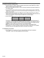
FIGURE 29: Getting to Know the Interface
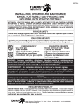
b. To establish a connection, click on the "System Configuration Tree" located on the top of the
Navigation Menu.
c. Within System Configuration Tree, select "Connections." Select "Configure" Tab and at the top of
the screen. Select "BACnet/IP Connection." Once highlighted green, click the "Start" button to
begin. See Page 41, Figure 30.
FIGURE 30: Configure
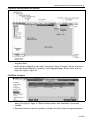
d. Switch to "Network Tree" (See Page 41, Figure 29) in the Navigation Menu to download air handler(s). See Page 42, Figure 31. Within the action buttons, click "Downloads" if not already
selected.
e. Expand the network to reveal air handler(s) available. Click "Start" button to begin downloading.
41 of 61
RAPID® INFINITYPRO™ USER, OPERATION AND SERVICE MANUAL
FIGURE 31: Download
f. Once download is complete, switch to "Geographic Tree" (See Page 41, Figure 29) in the Navigation Menu. See Page 42, Figure 32. Select the site to list all air handlers on the network. Within the
action buttons, verify "Graphics" is selected.
FIGURE 32: Air Handler Network Tree
g. Select specific air handler (AHU) to receive/view graphics.
h. Navigate within the interface to complete actions, reference Help menu if needed.
Contact Rapid Engineering LLC with any additional questions at 800.968.0500.
42 of 61
KEYPAD
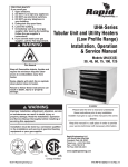
The maximum cable
length between router
and last air handler is
2,000 ft, Item 7
Maximum length
of room sensor
or Keypad cable
is 500 feet Item 8
KEYPAD can be
plugged into the
bottom of the room
sensor Item 6
Item 5
Power supply
for router Item 2
Router Network Information:
·
IP Address:
·
Subnet Mask:
·
Gateway:
PC Network Information:
·
IP Address:
·
Subnet Mask:
·
Gateway:
Customer:
·
Sales Order Number:
·
Number of Air Handlers:
Item 4
Room
Sensor
Item4
Room
Sensor
Item 4
Room
Sensor
Item 4
Room
Sensor
Repeater
RAPID
AIR # 4
RAPID
AIR # 3
RAPID
AIR # 2
RAPID
AIR # 1
BAS Router
MS/TP_IP
Item 1
Customer's
PC 1
RAPID
AIR # 5
Stand alone PC running
WebCTRL Software
Local access only
OR
Customer's server
running WebCTRL
software Internet
access available
Use repeater to extend network
beyond 2,000 ft or when more
then 32 units or to create a "T" in
the network cable Item 9 and 10
Cable to last
air handler
Repeater
Customer's
Ethernet
Customer's
PC 2
Customer's
PC 3
Customer's
PC 4
{
Public
Internet
REPEATER B&B 4850PDR DIN RAIL MOUNT
9
10
22985
POWER SUPPLY B&B MDR-20-24 DIN RAIL MOUNT
KEYPAD / SENSOR CABLE 18/4 WEST PENN 3244
8
N/A
NETWORK CABLE BELDEN 2 WIRE WITH SHIELD 3105A
KEYPAD CABLE WITH R-NET CONNECTOR
INSTALLER
INSTALLER
INSTALLER
INSTALLER
RAPID
RAPID
RAPID
KEYPAD
RAPID
ROOM SENSOR WITH R-NET CONNECTION
RAPID
RAPID
SUPPLIER
Access to WebCTRL
through the public
Internet is set up by
the customers's IT
personnel
DIN RAIL FOR ROUTER
POWER SUPPLY WASU24-450 WALL TRASFORMER
BAS ROUTER BACnet/IP TO MS/TP
22984
7
N/A
5
00246
6
4
12100
22965
3
2
1
ITEM MFG.PART NUMBER & DESCRIPTION
08619.1
22877
10249
RAPID #
Note: If stand alone PC is used the
default IP for the router will be
192.168.92.68 the PC IP address will
need to be set to match with the
exception of the last set of digits.
Firewall
Any PC in
World
Any PC in
World
SECTION 5: WEB CONTROL SOFTWARE FRONT-END COMMUNICATION
FIGURE 33: Sensor / Network Cable for InfinityPro
43 of 61
RAPID® INFINITYPRO™ USER, OPERATION AND SERVICE MANUAL
FIGURE 34: Cabling and Network Specifics for Use with One Handler
44 of 61
SECTION 5: WEB CONTROL SOFTWARE FRONT-END COMMUNICATION
FIGURE 35: Cabling and Network Specifics for Use with Multiple Air Handlers
45 of 61
RAPID® INFINITYPRO™ USER, OPERATION AND SERVICE MANUAL
SECTION 6: USER INTEGRATION POINTS
6.1 User Integration Points
6.1.1 Operating Types
NOTE: Default values are represented in bold.
Point Type/ID
Read/
Write
AV:7
R/W
MSV:2
R/W
1 = Handheld Keypad
2 = Building Management (Automation) System
3 = WebCTRL
AV:5
R/W
This point is used by the controls integrator to put the air
handler into
the occupied period when the schedule source is via the
building management system.
0 = Unoccupied
1 = Occupied
BV:1
R/W
MSV:1
R/W
Point Type/ID
Read/
Write
Point Name
Description
Select Operating Mode
0 = Off
1 = On
2 = Auto
Select Damper Control
1 = Manual - manually set the damper position
2 = Pressure - dampers modulate to maintain Auto Room
Pressure
Select Schedule Source
Select Occ/Unocc Peri
od On/Off
Select Economizer Type
Use this point to enable the economizer control
1 = No Economizer
2 = Economizer
6.1.2 Operating Status
Point Name
Description
AV:17
R
Status Damper Control
Report the status of the current operation: On, Off, Auto or
Flush.
Reports the status of the dampers: Auto or Manual
AV:14
R
Status Schedule Cntrl
Source
Reports the status of the Schedule Source: Handheld keypad, Building Management (BAS) System or WebCTRL
AV:19
R
Status Occ / Unoccupied
Reports current status of operation: Occupied or Unoccupied
BV:2
R
Reports status of Economizer: On or Off
BV:3
R
Status Operating Mode
Status Economizer On/
Off
46 of 61
SECTION 6: USER INTEGRATION POINTS
6.1.3 Heat Settings
Point Name
Stpt Occupied Htg
Stpt Unoccupied Htg
Stpt Heat Off range
2-20 degrees
Stpt Min Supply Air
Temp
Stpt Max Supply Air
Temp
Stpt Forced Supply Air
Temp
Stpt OA Heat Disable
Stpt OA Heat Enable
Stpt Low Temp
Shutdown
Status Burn Output
Status Active Heating
Set Point
Status Fan On
Description
During the occupied period, burner starts based on desired
room temperature when heating control type selected is
Room Air Temperature Control or Forced Supply Air Heating. Default value is 70 °F.
During the unoccupied period, the fan and burner will start
if the room temperature drops below this setting and the
temperature select type is Room Air Temperature Control
or Forced Supply Air Heating. Default value is 55 °F.
During the occupied and unoccupied period, the heat shuts
off when the room temperature reaches the Heat Off Setting when operating in the Room Air Temperature Control
and Forced Supply Air Heating. The Heat Off Setting is
defined by entered value which is then added to Heat Setting Current. Default value is 3 °F.
Limits the minimum supply air temperature to this setting
when the heat is on. Applies to Room Air Temperature Control and Outdoor Air Room Control. Default value is 60 °F.
Limits the maximum supply air temperature to this setting
when the heat is on. Applies to Room Air Temperature Control and Outdoor Air Room Control. Default value is 95 °F.
Applies when the Forced Supply Air Heating is selected.
The heat modulates to control the supply air at this setting
regardless of the room temperature. Default value is 70 °F.
Applies to all heating types. When the outside air temperature reaches this set point, the burner will shut off regardless of room temperature. Default value is 95 °F.
Applies when the Outdoor Air Room Control is selected.
The burner will turn on when the outside air temperature
falls below this set point. Default value is 50 °F.
If in the heating mode and the supply air temperature is
below this set point for more than 5 minutes, the operating
mode is switched to Off. Default value is 40 °F.
Value is 0% to 100%. Output from the controller to the modulating heat source.
The Heat Setting Current is determined by the time clock
and occupied / unoccupied heat settings.
Reports the status of fan: On or Off
Point Type/ID
Read/
Write
AV:2
R/W
AV:1
R/W
AV:26
R/W
AV:30
R/W
AV:29
R/W
AV:25
R/W
AV:32
R/W
AV:31
R/W
AV:27
R/W
AV:13
R
AV:11
R
BV:7
R
Reports the status of the heat source: On or Off. Heat
Source options (Direct-Fired Burner, Electric, Steam or Hot
Water)
Reports the setpoint at which the heat source turns off
BV:8
R
AV:12
R
Reports current outside air temperature
AV:8
R
Status DA Temp
Reports current discharge air temperature
AV:20
R
Status Room
Temperature
Reports current temperature in the building
AV:22
R
Reports current percentage output to variable frequency
drive based on unit operation
AV:18
R
Status Heat On_Off
Status Heat Off Stpt
Status OA Temperature
Status Output to VFD
47 of 61
RAPID® INFINITYPRO™ USER, OPERATION AND SERVICE MANUAL
6.1.4 Cooling Settings
Point Type/ID
Read/
Write
Stpt Cooling
When the room temperature reaches the Cooling setting,
the first stage of cooling is enabled. The Cooling set point
cannot be set below the Heating Off Setting plus one.
Default value is 74 °F.
AV:4
R/W
Stpt OA Limit
Defines the setting for Economizer cooling. Default Valve is
65 °F.
AV:24
R/W
Reports current cooling setpoint
AV:10
R
Reports current condition of cooling: On or Off
BV:4
R
Point Name
Status Cooling Stpt
Status Cooling Stage
Description
6.1.5 Damper Control
Point Name
Description
Point Type/ID
Read/
Write
Stpt Manual Damper
Position
When in the Manual Percent Outdoor Air setting, the dampers will bring in the amount of outside air defined by this
setting.
AV:28
R/W
Stpt Building Static
Pressure
When in the Auto Room Pressure setting, the dampers will
modulate open and closed to control the room pressure to
this setting.
AV:23
R/W
Status Total OA
Percent
For AM and VAV models with inlet dampers. Reports mixing damper position plus the burner supply air damper
position to give you the total outside air in a percentage.
AV:21
R
Status Manual Damper
Position
Reports current setpoint (percentage) for manual outside
air setting
AV:15
R
Reports current building pressure (differential pressure)
AV:9
R
Point Type/ID
Read/
Write
Status Building Pressure
6.1.6 Alarms
Point Name
Description
Fan Contactor Not On
See Page 52, Section 7.3.1
BV:9
R
Fan Contactor On When
Should Be Off
See Page 52, Section 7.3.2
BV:10
R
Damper for Heat Air Not
Open
See Page 52, Section 7.3.3
BV:11
R
Damper for Heat Air Not
Closed
See Page 53, Section 7.3.4
BV:12
R
Burner Lockout or
Safety SW Not Made
See Page 53, Section 7.3.5
BV:13
R
Low Supply Air Temp
Shutdown
See Page 56, Section 7.3.6
BV:14
R
Dirty Filters
See Page 57, Section 7.3.7
BV:15
R
Low Building Pressure
See Page 58, Section 7.3.8
BV:16
R
48 of 61
SECTION 6: USER INTEGRATION POINTS
6.1.7 Auto Discovery
Display Name
Select Schedule Source
Select Occ/Unocc Period On/Off
Select Operating Mode
Select Damper Control
Select Economizer Type
Status Schedule Cntrl Source
Status Occ / Unoccupied
Status Operating Mode
Status Fan On
Status Output to VFD
Status Active Heating Setpt
Status Heat Off Stpt
Status DA Temp
Status Cooling Stpt
Status Room Temperature
Status OA Temperature
Status Heat On_Off
Status Heat Output
Status Damper Control
Status Manual Damper Position SP
Status Total OA Percent
Status Building Pressure
Status Economizer On/Off
Status Cooling Stage
Stpt Occupied Htg
Stpt Unoccupied Htg
Stpt Heat Off range 2 - 20 degrees
Stpt Cooling
Stpt Bldg Static Pressure
Stpt Manual Damper Position
Stpt Max Supply Air Temp
Stpt Min Supply Air Temp
Stpt Forced Supply Air Temp
Stpt OA Heat Disable
Stpt OA Heat Enable
Stpt Low Temp Shutdown
Stpt OA Limit
Alarm Burner Supply Damper LS Did
Not Make
Alarm Energy Alert
Alarm Fan Contactor Hand Mode
Alarm Filters Dirty
Alarm Gas Valve LS Did Not Make
Alarm Low Temp Shutdown
Alarm Supply Damper LS Did Not Open
Alarm Supply Fan Fail
Keypad Schedule Enable
Read/
Write
R/W
R/W
R/W
R/W
R/W
R
R
R
R
R
R
R
R
R
R
R
R
R
R
R
R
R
R
R
R/W
R/W
R/W
R/W
R/W
R/W
R/W
R/W
R/W
R/W
R/W
R/W
R/W
Units
no units
Default
Value
Object Object
Type
ID
sched_source
enable_bas
op_mode_select
set_damp_ctrl
econ_type
status_sch_Cntr_Source
occ_status
status_op_mode
status_fan_on
vfd_spd
eff_htg_stpt
status_heat_off_sp
status_da_temp
eff_clg_stpt
status_room_temp
status_oa_temp
heat_enable
status_burn_output
status_damp_ctrl
status_man_damp_sp
status_oa_total
eff_bldg_pres
status_econ_active
status_clg_stg
occ_htg_stp
unocc_htg_stp
burn_off-delta
occ_clg_stp
bldg_press_stpt
fxd_dmpr_pos
max_dat_stpt
min_dat_stpt
DA_Temp_Sp
oa_heat_disable
oa_heat_en_sp
Low_Temp_Shutdown
OA_Econ_Limit_Stpt
AV
BV
AV
MSV
MSV
AV
BV
AV
BV
AV
AV
AV
AV
AV
AV
AV
BV
AV
AV
AV
AV
AV
BV
BV
AV
AV
AV
AV
AV
AV
AV
AV
AV
AV
AV
AV
AV
5
1
7
2
1
19
2
17
7
18
11
12
20
10
22
8
8
13
14
15
21
9
3
4
2
1
26
4
23
28
29
30
25
32
31
27
24
R
heat_damp
BV
9
R
R
R
R
R
R
R
R/W
low_pressure
fan_forced
filters_dirty
gas_valve
low_temp
heat_damp_force
fan_fail
enable_keypad
BV
BV
BV
BV
BV
BV
BV
BV
10
11
12
13
14
15
16
17
no units
1
Inactive (0)
0
1
1
Reference Name
no units
no units
%
°F
no units
°F
°F
no units
°F
%
no units
%
%
in H2O
°F
°F
°F
°F
in H2O
%
°F
°F
°F
°F
°F
°F
°F
70
55
3
74
0.01
50
95
60
70
95
50
40
65
Inactive (0)
49 of 61
RAPID® INFINITYPRO™ USER, OPERATION AND SERVICE MANUAL
SECTION 7: TROUBLESHOOTING
DANGER
Electrical Shock Hazard
Severe Injury Hazard
Disconnect electric before service.
Do not enter equipment while in operation.
More than one disconnect switch may be
required to disconnect electric from
equipment.
Equipment may start automatically.
Equipment must be properly grounded.
Installation, operation and service must be
done by a trained technician only.
Do not operate with door open.
Failure to follow these instructions can result in death, electrical shock or injury.
WARNING
Explosion Hazard
Fire Hazard
Turn off gas
supply to
equipment before
service.
Keep all
flammable
objects, liquids
and vapors the
minimum required
clearances to
combustibles
away from
equipment.
Falling Hazard
Burn Hazard
Use proper safety Allow equipment
to cool before
equipment and
practices to avoid service.
falling.
Internal components of
Do not use any
part of equipment equipment may
still be hot after
as support.
operation.
Cut/Pinch Hazard
Wear protective
gear during
installation,
operation and
service.
Edges are sharp.
Some objects will
catch fire or
explode when
placed close to
equipment.
Failure to follow these instructions can result in death, injury or property damage.
7.1 Initial Checks
When encountering any abnormal operation or fault conditions of the equipment, all the troubleshooting
should start with the following initial checks. If a problem is discovered in these initial checks, it must be corrected before moving on in the troubleshooting.
1. The air handler may have any number of possible heat sources (electric, gas, hot water or steam) or
none at all. Several cooling options are also available (evaporative, DX, chilled water).
50 of 61
SECTION 7: TROUBLESHOOTING
2. If the air handler does not include a feature as described in this Troubleshooting Guide, disregard information provided for that feature. (As indicated above in item #1, some features are optional and not
included with every air handler.)
3. The following voltages are used for the control circuitry: 120 volts AC, 24 volts AC, 5 volts DC, 0-20 VDC
and 0-10 VDC.
4. Refer to the air handler wiring diagram for aid in locating the error.
5. The Maxitrol modulating / regulating valve (direct-fired models) and its associated circuitry is powered
by a 0-20 VDC signal. The RAPID® InfinityPro™ controller provides a 0-10 VDC signal to a signal conditioner, which then converts the signal to 0-20 VDC.
7.2 General Troubleshooting
1. Compare voltage and phase of power supply on site with rating plate information.
2. Review wiring diagram. Do the electrical connections match the supplied wiring diagram?
3. Compare the gas type and supply pressure on site with rating plate information.
4. Check for proper blower rotation on air handler.
• Blowers paired with a three phase motor can be reversed by swapping any two incoming power legs.
For blowers powered by a single phase motor, refer to the motor rating plate for reversing instructions.
5. For additional information on supplemental temperature sensor information, See Page 58, Section
7.3.9.
7.2.1 Fuses / Overloads Tripping
Frequent tripping of the electrical safety devices often indicate an electrical or duct design problem.
Investigate carefully to determine the underlying cause, consulting the National Electrical Code as necessary. Possible causes for tripping include:
1. The voltage supply to the air handler is too low. Check the transformer taps. Check wire size and length
for excessive voltage drop.
2. The feeder breaker or fuses are undersized. Correct the improper component.
3. Air handler CFM is too high, causing excessive current draw. This occurs when the actual static pressure is significantly less than expected and specified. Consult Rapid Engineering LLC if additional
assistance is required.
7.2.2 Flame Relay
The Honeywell flame relay RM7897C 1000 is equipped with an interrupted pilot. The pilot is extinguished
after the main flame is established. A "Test/Run" switch is provided on these relays. The relay remains in the
original mode before it was placed in the "Test" position. If the flame relay appears to be "stuck", it may be
attempting to operate in the "Test" position. For normal operation, the "Test/Run" switch should always be in
the "Run" position.
7.3 Alarm Description
There are a number of safety features included with the air handler. If a problem occurs during normal operation, a red alarm light on the handheld keypad will illuminate and an alarm description will appear. This is an
indication to the user there is an alarm condition.
To reset the alarm light, push and hold the FN button, then press MUTE. To permanently clear an alarm light,
the fault must be corrected. Based on information below, fault can properly be corrected.
51 of 61
RAPID® INFINITYPRO™ USER, OPERATION AND SERVICE MANUAL
7.3.1 Alarm Description: Fan Contactor Not On
This alarm occurs if input number 5 on the controller fails to activate while the fan is commanded to start and
the unit is in the occupied period.
a. Reset the overloads. If the overloads continue to trip, check motor running amperage against
motor name plate full load amperage. If greater than full load rating, determine cause of over
amperage. (e.g., low service voltage, excessive voltage drop.)
4. The auxiliary contact is defective.
a. Replace the fan contactor (built in)
5. Check for loose wiring between terminals
6. Defective contactor (M1).
a. Check for voltage (120 volts) at the contactor coil. If there is voltage and the contactor does not pull
in, the energizing coil is defective. If the contactor pulls in but does not start the fan, the contacts
are defective. Replace the contactor.
7. An interlock (smoke detector or access door limit switch) is open and power to the control circuit has
been interrupted.
a. Check appropriate interlock.
7.3.2 Alarm Description: Fan Contactor On When It Should Be Off
This alarm occurs when input 5 at the controller is on when it should be off. It indicates the supply fan contactor has been activated before the fan has been commanded on or after the fan has been commanded off.
Since this contactor should not be powered when the fan is not commanded to be on, an alarm is reported.
1. The auxiliary contact to the starter is jumped and/or shorted.
a. Remove jumper or replace auxiliary contact on starter.
2. The M1 motor contactor has failed closed.
a. Replace the contactor.
3. The fan motor initiate relay is wired incorrectly or defective.
a. Verify the wiring is connected to the relay coil and contacts as is illustrated on the wiring diagram.
Rewire relay if necessary.
b. If the normally open contacts on the relay have failed closed, replace the fan motor initiate relay.
4. The fan relay on output relay is wired incorrectly or has failed closed.
a. Verify the wiring is connected to the relay coil and contacts as is illustrated in air handler wiring diagram. Rewire relay if necessary.
b. If the normally open contacts on the relay have failed closed, replace the fan relay on output relay.
7.3.3 Alarm Description: Damper for Heat Air Not Open
This alarm occurs when the end switch in the heat air damper fails to close on input number 4 at the controller.
1. A mechanical problem is preventing the damper from opening.
a. Check for and remove any obstructions (ice formations) that may be preventing the damper from
opening when powered.
b. Disconnect the linkage and manually operate the damper to determine the cause of binding.
Clean, lubricate, adjust, and repair as necessary.
2. The wiring for the heat air damper or the limit switch is loose or defective.
a. Trace the voltage from the output relay to the motor and back to the input relay and repair the problem.
52 of 61
SECTION 7: TROUBLESHOOTING
3. The heat air damper limit switch is defective or needs adjustment.
a. Observe the limit switch response to successively energizing and de-energizing the damper motor.
Adjust the limit switch for appropriate response to operation of the motor. If the switch is unable to
be adjusted properly, replace the motor.
4. The heat air damper output relay or limit switch input relay are defective.
a. Verify wiring is connected to the relay coil and contacts as is illustrated in air handler wiring diagram.
b. Check proper contact operation as damper should open and close when relay is energized and deenergized. Replace relay if necessary.
5. The heat air damper motor is defective.
a. If the motor fails to open when power is applied, (and the damper operation is not restricted)
replace the motor.
6. An interlock (smoke detector or access door) is open and power to the control circuit has been
interrupted.
a. Check appropriate interlock.
7.3.4 Alarm Description: Damper for Heat Air Not Closed
This alarm occurs when input number 4 on the controller remains open and the heat air inlet damper should
be closed. The damper for the heat inlet air fails to close when the fan is shut off. The damper remains open
when fan is off. The heat air damper actuator is a power open spring return actuator.
1. A mechanical problem is preventing the damper from closing.
a. Check for and remove any obstructions (ice formations) that may be preventing the damper from
opening when powered.
b. Disconnect the linkage and manually operate the damper to determine the cause of binding.
Clean, lubricate, adjust, and repair as necessary.
2. The heat air damper limit switch is defective or needs adjustment.
a. The damper is closed but the limit switch in the actuator is still made.
b. Adjust the switch or replace the actuator as needed.
3. The heat air damper output relay has failed
a. Check proper contact operation as damper should open and close when relay is energized and deenergized. Replace relay if necessary.
7.3.5 Alarm Description: Burner Lockout Or Safety SW Not Made
This alarm occurs when input number 6 on the controller drops out or is not made when there is a call for
heat. Prior to generating this alarm, the normal start-up sequence includes a time delay of 120 seconds from
the time the heat start relay, output 3, is energized. There are a number of safety devices wired in series with
each other, if any of them open during a call for heat, the burner is de-energized and this alarm is generated.
See below for possible causes.
1. Possible Cause of Burner Lockout or Safety SW Not Made: Airflow
An airflow switch on the air handler measures the pressure drop across the burner to ensure proper air
velocity for combustion. The switch is pre-set to open if the airflow is low and the pressure drops fall below
0.2" w.c.. The switch additionally includes a pre-set to open if the airflow is too high and the pressure drop
across the burner exceeds 1.35" w.c.. The target standard operating pressure drop is 0.9" w.c.. This can be
measured by connecting a monometer to airflow switch pitot tubes.
53 of 61
RAPID® INFINITYPRO™ USER, OPERATION AND SERVICE MANUAL
1. Belts are loose, sheaves are worn.
a. Tighten or replace belts per Rapid Engineering LLC specifications and belt manufacturer's recommendations. NOTE: Never replace only one belt in a set, as belts will elongate. Replace entire set
if necessary.
b. Check for worn drive sheaves and replace as needed.
2. Filters are dirty, preventing adequate airflow.
a. Replace the filters.
3. Airflow switch tubing is plugged, preventing it from closing.
a. Clear the tubing.
4. Fan rotation is reversed.
a. Turn off disconnect switch and reverse two power wires, preferably at the line side of the disconnect. (High importance for pony motor drives or two speed motors) The wires on the load side of
the disconnect may be reversed for single speed, single motor air handlers NOTE: The wide edge
of the fan blades should be the leading edge.
5. Airflow switch is defective and has failed to close.
a. Measure the pressure drop across the burner and compare it to the set point of the airflow switch
to determine if the switch is bad. Replace switch if necessary.
6. Supply or discharge damper is not open.
a. Check linkage and repair.
7. Access door is open.
a. Close the door.
8. Fan is overloaded.
a. Verify and compare the actual external static installed (ductwork) to design external static (ESP) to
make sure the fan is not overloaded.
b. Consult Rapid Engineering LLC for additional information.
2. Possible Cause of Burner Lockout or Safety SW Not Made: High Gas Pressure Switch
The high gas pressure switch is a normally closed switch that opens on a pressure rise to protect the equipment from over firing. The factory set point is 1.5" w.c above the high fire gas pressure set point. FM manifolds are manual reset type, XL and ANSI manifolds are automatic reset type.
1. The burner high fire gas pressure is set to high.
a. Compare the actual high fire gas pressure to the rating plate on the air handler. Adjust the actual
gas pressure as needed.
2. The utility gas pressure exceeded 5psig, overpowering the modulating / regulating valve's pressure regulator.
a. Install an additional pressure regulator to reduce the incoming pressure to below 5psig.
3. The modulating / regulating valve's pressure regulator has failed.
a. Replace the regulator.
4. The high gas pressure switch is set too low.
a. Adjust the gas pressure switch setting to 1.5" w.c above the high fire setting.
5. The high gas pressure switch is defective.
a. Measure gas pressure at switch. Determine if gas pressure is actually lower than the high gas
pressure switch set point. Replace the switch if necessary.
54 of 61
SECTION 7: TROUBLESHOOTING
3. Possible Cause of Lockout or Safety SW Not Made: Low Gas Pressure Switch
The low gas pressure switch is a normally closed switch that opens on a pressure fall to protect equipment
from under firing and potentially deliver unburned fuel to the conditioned space. Consult the equipment data
plate for the proper setting. FM manifolds are manual reset type, XL and ANSI manifolds are automatic reset
type.
1. The manual gas valve is closed.
a. Open manual gas valve
2. The utility inlet gas pressure dropped lower than the minimum inlet supply gas pressure required for the
air handler.
a. Investigate causes for low supply gas pressure. Possible causes could be a valve closed downstream or insufficient pipe sizing to air handler.
b. Close manual gas valve and remove any obstructions found in gas line.
3. The switch is not set properly.
a. The switch should be set to the minimum inlet gas pressure setting as indicated on the air handler
rating plate.
4. The low gas pressure switch is defective
a. Verify the supply inlet gas pressure is higher than switch set point. If switch will not close, replace
it.
4. Possible Cause of Lockout or Safety SW Not Made: High Temperature Limit Switch Tripped
The supply air high temperature limit switch is a normally closed switch factory set at 150 degrees Fahrenheit. The switch opens when the supply air exceeds the set point of the switch. The high temperature limit
switch is a manual reset. The purpose of the high temperature limit switch is to prevent damage to the air
handler fan motor and drive.
1. The maximum discharge temperature set point is set to high.
a. Set the maximum discharge air temperature set point to 95 degrees Fahrenheit.
2. The modulating regulating valve high fire gas pressure regulator is set to high.
a. Setup the modulating regulating valve to meet the factory specifications for the air handler.
3. The high temperature limit switch is set too low.
a. Set the switch for 150 degrees Fahrenheit.
4. The high temperature limit switch is defective.
a. Replace the switch.
5. Possible Cause of Lockout or Safety SW Not Made: Burner Control Safety Lockout
The Honeywell 7800-Series burner control defaults into safety lockout during certain conditions. The Honeywell 7897 burner control features an LED blink pattern when in lockout condition. The fast blinks identify the
tens portion of the fault code (3 fast blinks is 30) while the slow blinks identify the units portion of the fault
code (2 slow blinks is 2). For a complete list of fault codes refer to the Honeywell burner control literature.
1. No flame signal present during the trial for ignition period.
a. Check that the supply gas pressure meets that air handler specifications.
b. Make sure all of the manual shut off valves are open.
c. Check the pilot line gas pressure at the "T" in the pilot line down stream of the pilot valve solenoid
and the pilot regulator. Typical pilot line gas pressure is approximately 2" w.c differential resulting in
a pilot flame about the size of a baseball. If no pressure is present either the pilot regulator or pilot
solenoid valve may be defective.
55 of 61
RAPID® INFINITYPRO™ USER, OPERATION AND SERVICE MANUAL
d. Check the igniter, clean or replace if needed.
e. Remove and clean the lens of the UV scanner with a soft cloth.
f. Check the UV scanner by holding a flame in front of the UV scanner lens. Look for the flame LED
light on the burner control to come on. If it does not come on, the UV scanner has most likely
failed.
g. Check the ignition transformer; make sure the wiring to the igniter is good and not grounded out.
2. The flame signal is lost during the main flame establishing period or during the run period.
a. Make sure the burner orifices are clean. See RAPID® 4000-Series Industrial Air Handler Installation, Operation and Service Manual (RP140000NA) Maintenance Section and drill burner orifices
out with the correct size drill bit.
b. Remove and clean the lens of the UV scanner with a soft cloth.
c. Check the burner low fire setting. The flame length at a minimum firing rate must be long enough
for the UV scanner to see the flame.
d. Make sure the primary and block gas valves are opening during the main flame establishing
period.Optimum low-fire flame length setting is 1" - 2". Ensure that there is a continuous ribbon of
flame with no gaps. Gaps are most likely to occur at "T" intersections on the burner.
7.3.6 Alarm Description: Low Supply Air Temp Shutdown
This alarm occurs when the supply air temperature drops below the Fan Off If Supply Air Temp Below setting
for more than 5 minutes and there is a call for heat.
1. Heat system failure.
a. The control module detects problems with other areas of operation, it will not allow the burner to
light. This, in turn, may allow the supply air to fall below the low temperature set point for 5 minutes.
b. Check the Alarms log to see if another code has preceded it by 5 minutes and follow that alarm
code's explanation of possible trouble.
2. The burner requires maintenance.
a. See RAPID® 4000-Series Industrial Air Handler Installation, Operation and Service Manual
(RP140000NA) Maintenance Section and drill burner orifices out with the correct size drill bit.
b. Check burner gas pressure and compare it to the unit rating tag, adjust if needed.
3. The manual gas valve is closed or there is a blockage in the gas line.
a. Open the valve or open the dirt leg cap and remove any blockage.
4. The discharge sensor, its cable or its connection to the control module is off or defective.
a. Verify proper discharge sensor operation and cable connections and repair as necessary.
5. The connection from the control module to the modulating valve is defective or off.
a. Repair the connector or cable as necessary.
6. Low limit set point is set too high. (Factory default is 40 degrees Fahrenheit.)
a. Adjust the low limit set point to an appropriate value.
7. The modulating gas valve does not open to allow high fire. The valve should modulate progressively
more open as the voltage from the controller rises above 5 volts DC, and continue opening until the voltage exceeds 15-19 volts DC.
a. Repair or replace the valve and adjust high and low-fire flames as needed.
8. Ignition did not occur.
56 of 61
SECTION 7: TROUBLESHOOTING
a. The igniter (spark plug) is defective, fouled or shorting against the burner end plate. Check that it is
properly installed, has a clean (no carbon) gap of about 3/32" (2.5mm) and no cracks in the
ceramic. Clean the electrode with a wire brush if necessary.
b. The ignition transformer is not receiving power or putting out the proper (6000V) voltage. Determine the cause and repair.
c. If spark is present in the test above, air may be present in the gas line. Purging of air in a new line
may be required. An LP system may need purging if the tank ran out of gas before refilling.
9. The flame verification signal (ultraviolet light) is not present. Possible causes include:
a. Dirty UV scanner. Clean the scanner with a soft cloth.
b. Plugged UV scanner sight tube. Remove the obstructions.
c. UV scanner not secured firmly to the sight tube. Screw the scanner on firmly, but only finger tight.
d. Defective UV scanner. Replace the scanner.
e. Loose or defective UV scanner wiring. Determine the location of the problem and repair.
f. A defective flame relay or UV amplifier. Replace the defective component.
10.Pilot manual valve is closed.
a. Open valve.
11. Pilot solenoid valve is defective.
a. Replace solenoid
12.Low pilot flame.
a. Increase pilot gas pressure by adjusting pilot regulator. The outlet pressure at the pilot regulator
should be about 2" w.c, resulting in a pilot flame about the size of a baseball.
13.The airflow switch setting is too low, causing frequent flame relay power cycling.
a. Set the switch properly per the Service Technician Manual.
14.Wires on flame relay terminals are disconnected or loose
a. Remove the relay from its base and check.
15.Ignition wire is broken or grounded against unit.
a. Repair the wire or isolate from ground.
16.The primary, block or vent valve actuator is defective.
a. Replace the faulty actuator.
NOTE: Honeywell 7800 flame relays are designed to allow remote resetting. The burner is
reset every time the air handler is turned off and then returned to the On or Auto mode.
7.3.7 Alarm Description: Dirty Filters
1. The filters are dirty or the belts are loose.
a. Change the filters
b. Check the fan belts replace or tighten per the maintenance manual.
2. Motor or fan sheaves are worn
a. Replace the worn sheaves with new. Confirm replacement sheaves are the correct size consult
factory if necessary.
3. The clogged filter switch has failed.
a. Verify the pressure drop across the filters and compare it to the set point of the clogged filter switch
to determine if the switch is working correctly.
57 of 61
RAPID® INFINITYPRO™ USER, OPERATION AND SERVICE MANUAL
7.3.8 Alarm Description: Low Building Pressure
This alarm occurs when there is a call for heat and the air handler is operating in the Occupied Heating setting with Auto Room Pressure heating type. The air handler has been unable to maintain a positive building
pressure within .01" w.c. of the pressure set point for 10 consecutive minutes. As a result, the program has
placed the outside air dampers in the minimum outside air position and the air handler in the Unoccupied
Setback Temp setting. This setting will be maintained until the situation causing the lack of building pressure
has been corrected or after a maximum of 20 minutes. Once either of these conditions has occurred, the program will then return the air handler to the Occupied Heating setting with Auto Room Pressure heating type.
The cycle will restart again in 10 minutes if the situation that caused the building pressure drop has not been
corrected. This alarm occurs only if the heating control type has been configured for the Low Building Pressure option. This alarm is a report of the Low Building Pressure condition, there is no problem with the software or hardware.
1. Determine why the building pressure is less then set point.
a. Most common cause is open over head garage doors
b. Close the doors
7.3.9 Supplemental Temperature Sensor Information
The thermistor temperature sensors change resistance to the Control Module proportionally to the temperature, with 10,000 ohms representing 77 °F. Each 1 °F drop in temperature causes an approximately 250 ohm
increase. The simplest way to check their performance is by using the temperature / resistance chart on
Page 59, Table 10. The display may indicate that a temperature sensor is "seeing" a very cold temperature
that is much colder than the actual temperature.
1. The sensor wiring is damaged or connected improperly.
a. Inspect all cabling for the sensor and repair as necessary.
b. Inspect all terminations and plug connections; make sure that they are making good electrical contact.
2. The sensor is defective.
a. Replace the sensor.
For burner equipped direct-fired air handlers which circulate room air, if the room or discharge air temperature sensors are defective, the RAPID® InfinityPro™ logic for temperature rise control will allow the burner to
light, but it will remain at low fire. Replace the defective sensor in order to restore proper operation.
58 of 61
SECTION 7: TROUBLESHOOTING
Table 10: Thermistor Performance
Temperature
Fahrenheit
0
5
10
15
20
25
30
35
40
45
50
55
60
65
70
75
80
85
90
95
100
105
110
115
120
125
Ohms
85,350
72,910
62,480
53,640
46,230
39,910
34,560
30,000
26,100
22,760
19,900
17,440
15,310
13,480
11,880
10,500
9,298
8,250
7,331
6,532
5,826
5,209
4,663
4,182
3,757
3,381
Temperature
Celsius
-17.5
-15.0
-12.5
-10.0
-7.5
-5.0
-2.5
0.0
2.5
5.0
7.5
10.0
12.5
15.0
17.5
20.0
22.5
25.0
27.5
30.0
32.5
35.0
37.5
40.0
42.5
45.0
Ohms
84,106
72,910
62,523
55,408
48,453
42,438
37,235
32,736
28,830
25,432
22,474
19,900
17,686
15,736
14,029
12,520
11,190
10,019
8,984
8,066
7,251
6,532
5,897
5,332
4,827
4,374
NOTE: This table is applicable for the standard RAPID® temperature sensor, which is a thermistor. The
purpose of this table is to assist a service technician in diagnosing sensor related problems. Without
precision temperature measurement and a clear understanding of the accuracy specifications for these
sensors, it will be impossible to exactly duplicate the table data. Normal service test equipment, however,
used in conjunction with the table should indicate whether the sensor is operating properly.
59 of 61
RAPID® INFINITYPRO™ USER, OPERATION AND SERVICE MANUAL
60 of 61
SECTION 8: THE RAPID® INFINITYPRO™ WARRANTY
SECTION 8: THE RAPID® INFINITYPRO™
WARRANTY
RAPID ENGINEERING LLC WILL PAY FOR:
Within 24 months from date of purchase by buyer or 27
months from date of shipment by Rapid Engineering LLC
(whichever occurs first), replacement parts will be provided
free of charge for any part of the product which fails due to
a manufacturing or material defect.
Rapid Engineering LLC will require the part in question to
be returned to the factory. Rapid Engineering LLC will, at
its sole discretion, repair or replace after determining the
nature of the defect and disposition of part in question.
RAPID® Replacement Parts are warranted for the later of
12 months from date of shipment from Roberts-Gordon
LLC or the remaining RAPID® InfinityPro™ warranty.
RAPID ENGINEERING LLC WILL NOT PAY FOR:
Service trips, service calls and labor charges.
Shipment of replacement parts.
Claims where the total price of the goods have not
been paid.
Damage due to:
• Improper installation, operation or maintenance.
• Misuse, abuse, neglect, or modification of the
RAPID® InfinityPro™ in any way.
• Use of the RAPID® InfinityPro™ for other than its
intended purpose.
• Incorrect gas or electrical supply, accident, fire,
floods, acts of God, war, terrorism, or other casualty.
• Improper service, use of replacement parts or
accessories not specified by Rapid Engineering LLC.
• Failure to install or maintain the
RAPID® InfinityPro™ as directed in the User,
Operation and Troubleshooting Manual.
• Relocation of the RAPID® InfinityPro™ after initial
installation
• Use of the RAPID® InfinityPro™ in a corrosive
atmosphere containing contaminants.
• Use of the RAPID® InfinityPro™ in the vicinity of a
combustible or explosive material.
• Any defect in the RAPID® InfinityPro™ arising from a
drawing, design, or specification supplied by or on
behalf of the consumer.
• Damage incurred during shipment. Claim must be
filed with carrier.
WARRANTY IS VOID IF:
The RAPID® InfinityPro™ is not installed by an contractor
READ YOUR USER, OPERATION AND
TROUBLESHOOTING MANUAL.
If you have questions about your equipment, contact your
installing professional. Should you need Replacement
Parts or have additional questions, call or write:
Rapid Engineering LLC
1100 Seven Mile Road NW
Comstock Park, MI 49321
Telephone: +1.616.784.0500
Fax: +1.616.784.1910
Toll Free: 800.536.3461
www.rapidengineering.com
Rapid Engineering LLC's liability, and your exclusive
remedy, under this warranty or any implied warranty
(including the implied warranties of merchantability
and fitness for a particular purpose) is limited to
providing replacement parts during the term of this
warranty. Some jurisdictions do not allow limitations on
how long an implied warranty lasts, so this limitation may
not apply to you. There are no rights, warranties or
conditions, expressed or implied, statutory or otherwise,
other than those contained in this warranty.
Rapid Engineering LLC shall in no event be
responsible for incidental or consequential damages
or incur liability for damages in excess of the amount
paid by you for the RAPID® InfinityPro™. Some
jurisdictions do not allow the exclusion or limitation of
incidental or consequential damages, so this limitation or
exclusion may not apply to you. This warranty gives you
specific legal rights, and you may also have other rights
which vary from jurisdiction to jurisdiction.
Rapid Engineering LLC shall not be responsible for failure
to perform under the terms of this warranty if caused by
circumstances out of its control, including but not limited to
war, fire, flood, strike, government or court orders, acts of
God, terrorism, unavailability of supplies, parts or power.
No person is authorized to assume for Roberts-Gordon
LLC any other warranty, obligation or liability.
LIMITATIONS ON AUTHORITY OF
REPRESENTATIVES:
No representative of Rapid Engineering LLC, other than
an Executive Officer, has authority to change or extend
these provisions. Changes or extensions shall be binding
only if confirmed in writing by Rapid Engineering LLC's
duly authorized Executive Officer.
qualified in the installation and service of gas fired heating
equipment.
You cannot prove original purchase date and required
annual maintenance history.
The data plate and/or serial number are removed,
defaced, modified or altered in any way.
The ownership of the RAPID® InfinityPro™ is moved or
transferred. This warranty is non-transferable.
Rapid Engineering LLC is not permitted to inspect the
damaged equipment and/or component parts.
61 of 61