1
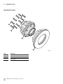
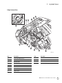
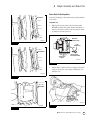
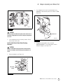
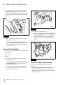
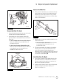
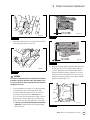
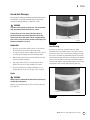
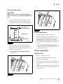
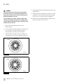
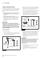
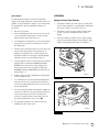
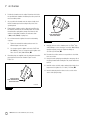
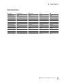
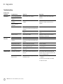
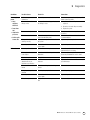
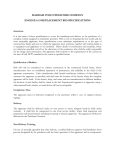
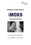
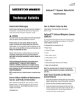
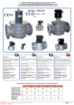
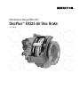
Maintenance Manual MM-0467
DiscPlus™ EX225 Air Disc Brake
Revised 06-06
Service Notes
About This Manual
ArvinMeritor’s Customer Service Center
This manual provides installation and maintenance procedures for
the DiscPlus™ EX225 air disc brake.
Call ArvinMeritor’s Customer Service Center at 800-535-5560.
Before You Begin
The DriveTrain Plus™ by ArvinMeritor Technical Electronic Library
DVD contains product and service information for most Meritor and
Meritor WABCO products. Specify TP-9853.
1.
Read and understand all instructions and procedures before
you begin to service components.
2.
Read and observe all Warning and Caution hazard alert
messages in this publication. They provide information that can
help prevent serious personal injury, damage to components,
or both.
3.
Follow your company’s maintenance and service, installation,
and diagnostics guidelines.
4.
Use special tools when required to help avoid serious personal
injury and damage to components.
Technical Electronic Library DVD
How to Obtain Tools and Supplies Specified
in This Manual
Call ArvinMeritor’s Commercial Vehicle Aftermarket at
888-725-9355 to obtain Meritor tools and supplies.
Hazard Alert Messages and Torque Symbols
WARNING
A Warning alerts you to an instruction or procedure that you
must follow exactly to avoid serious personal injury and
damage to components.
CAUTION
A Caution alerts you to an instruction or procedure that you
must follow exactly to avoid damage to components.
@ This symbol alerts you to tighten fasteners to a specified torque
value.
How to Obtain Additional Maintenance and
Service Information
On the Web
Visit Literature on Demand at meritorhvs.com to access product,
service, aftermarket, and warranty literature for ArvinMeritor’s truck,
trailer and specialty vehicle components.
Information contained in this publication was in effect at the time the publication was
approved for printing and is subject to change without notice or liability. Meritor Heavy
Vehicle Systems, LLC, reserves the right to revise the information presented or to
discontinue the production of parts described at any time.
Meritor Maintenance Manual MM-0467 (Revised 06-06)
Contents
1
Asbestos and Non-Asbestos Fibers
Section 1: Exploded Views
2
3
4
DiscPlus™ EX225 Air Disc Brake
Hub and Rotor Assembly
Caliper Sectional View
Adjuster Sectional View
5
Section 2: Introduction
6
Description
Operation
Automatic Adjustment
Operation Without Adjustment
Operation with Adjustment
Manual Adjustment and Deadjustment During a Pad
Change
pg. i
7
Section 3: Roadside Inspection
Intervals
Procedures
Inspection Procedure
Caliper Adjustment
Lining Wear
Rotor
Air Chamber
8
9
11
12
13
14
15
16
18
19
20
22
Section 4: Caliper Assembly and Brake Pad
Inspection
Caliper
Brake Deadjustment Procedure
Brake Adjustment Inspection
Brake Pad Removal and Inspection
Check Slide Pin Bushing Wear
Brake Pad Installation
Set the Initial Brake Pad-to-Rotor Running Clearance
Section 5: Caliper Components
Replacement
Introduction
Remove the Caliper Assembly
Install the Caliper Assembly
Replace the Adjuster Cover
Replace the Piston Boots
Remove the Caliper Bridge
Remove the Caliper Housing Assembly
Remove the Slide Pin Boots
Replace the Slide Pins
Install the Slide Pin Boots
Install the Caliper Housing Assembly
Install the Caliper Bridge
pg. 23
24
25
27
28
29
31
Section 6: Rotor
Inspection
Cracks
Heat Checking
Light Heat Checking
Heavy Heat Checking
Deep Grooves or Scores
Blue Marks or Bands
Measure the Rotor Thickness
Measure the Rotor Runout
Removal and Installation
Replace the Rotor
Section 7: Air Chamber
Introduction
Inspection
Cage the Spring Brake Chamber
Installation
Spring or Service Brake Chamber
Section 8: Specifications
Torque Specifications
32
Section 9: Diagnostics
Troubleshooting
Asbestos and Non-Asbestos Fibers
Figure 0.1
ASBESTOS FIBERS WARNING
NON-ASBESTOS FIBERS WARNING
The following procedures for servicing brakes are recommended to reduce exposure to
asbestos fiber dust, a cancer and lung disease hazard. Material Safety Data Sheets are
available from ArvinMeritor.
The following procedures for servicing brakes are recommended to reduce exposure to
non-asbestos fiber dust, a cancer and lung disease hazard. Material Safety Data
Sheets are available from ArvinMeritor.
Hazard Summary
Hazard Summary
Because some brake linings contain asbestos, workers who service brakes must understand the
potential hazards of asbestos and precautions for reducing risks. Exposure to airborne asbestos
dust can cause serious and possibly fatal diseases, including asbestosis (a chronic lung disease)
and cancer, principally lung cancer and mesothelioma (a cancer of the lining of the chest or
abdominal cavities). Some studies show that the risk of lung cancer among persons who smoke
and who are exposed to asbestos is much greater than the risk for non-smokers. Symptoms of
these diseases may not become apparent for 15, 20 or more years after the first exposure to
asbestos.
Most recently manufactured brake linings do not contain asbestos fibers. These brake linings may
contain one or more of a variety of ingredients, including glass fibers, mineral wool, aramid fibers,
ceramic fibers and silica that can present health risks if inhaled. Scientists disagree on the extent
of the risks from exposure to these substances. Nonetheless, exposure to silica dust can cause
silicosis, a non-cancerous lung disease. Silicosis gradually reduces lung capacity and efficiency
and can result in serious breathing difficulty. Some scientists believe other types of non-asbestos
fibers, when inhaled, can cause similar diseases of the lung. In addition, silica dust and ceramic
fiber dust are known to the State of California to cause lung cancer. U.S. and international
agencies have also determined that dust from mineral wool, ceramic fibers and silica are potential
causes of cancer.
Accordingly, workers must use caution to avoid creating and breathing dust when servicing
brakes. Specific recommended work practices for reducing exposure to asbestos dust follow.
Consult your employer for more details.
Recommended Work Practices
1. Separate Work Areas. Whenever feasible, service brakes in a separate area away from other
operations to reduce risks to unprotected persons. OSHA has set a maximum allowable level of
exposure for asbestos of 0.1 f/cc as an 8-hour time-weighted average and 1.0 f/cc averaged over
a 30-minute period. Scientists disagree, however, to what extent adherence to the maximum
allowable exposure levels will eliminate the risk of disease that can result from inhaling asbestos
dust. OSHA requires that the following sign be posted at the entrance to areas where exposures
exceed either of the maximum allowable levels:
DANGER: ASBESTOS
CANCER AND LUNG DISEASE HAZARD
AUTHORIZED PERSONNEL ONLY
RESPIRATORS AND PROTECTIVE CLOTHING
ARE REQUIRED IN THIS AREA.
2. Respiratory Protection. Wear a respirator equipped with a high-efficiency (HEPA) filter
approved by NIOSH or MSHA for use with asbestos at all times when servicing brakes, beginning
with the removal of the wheels.
3. Procedures for Servicing Brakes.
a.
Enclose the brake assembly within a negative pressure enclosure. The enclosure should be
equipped with a HEPA vacuum and worker arm sleeves. With the enclosure in place, use the
HEPA vacuum to loosen and vacuum residue from the brake parts.
b. As an alternative procedure, use a catch basin with water and a biodegradable, nonphosphate, water-based detergent to wash the brake drum or rotor and other brake parts.
The solution should be applied with low pressure to prevent dust from becoming airborne.
Allow the solution to flow between the brake drum and the brake support or the brake rotor
and caliper. The wheel hub and brake assembly components should be thoroughly wetted to
suppress dust before the brake shoes or brake pads are removed. Wipe the brake parts
clean with a cloth.
c. If an enclosed vacuum system or brake washing equipment is not available, employers may
adopt their own written procedures for servicing brakes, provided that the exposure levels
associated with the employer’s procedures do not exceed the levels associated with the
enclosed vacuum system or brake washing equipment. Consult OSHA regulations for more
details.
d. Wear a respirator equipped with a HEPA filter approved by NIOSH or MSHA for use with
asbestos when grinding or machining brake linings. In addition, do such work in an area with
a local exhaust ventilation system equipped with a HEPA filter.
e. NEVER use compressed air by itself, dry brushing, or a vacuum not equipped with a HEPA
filter when cleaning brake parts or assemblies. NEVER use carcinogenic solvents,
flammable solvents, or solvents that can damage brake components as wetting agents.
4. Cleaning Work Areas. Clean work areas with a vacuum equipped with a HEPA filter or by wet
wiping. NEVER use compressed air or dry sweeping to clean work areas. When you empty
vacuum cleaners and handle used rags, wear a respirator equipped with a HEPA filter approved
by NIOSH or MSHA for use with asbestos. When you replace a HEPA filter, wet the filter with a fine
mist of water and dispose of the used filter with care.
5. Worker Clean-Up. After servicing brakes, wash your hands before you eat, drink or smoke.
Shower after work. Do not wear work clothes home. Use a vacuum equipped with a HEPA filter to
vacuum work clothes after they are worn. Launder them separately. Do not shake or use
compressed air to remove dust from work clothes.
6. Waste Disposal. Dispose of discarded linings, used rags, cloths and HEPA filters with care,
such as in sealed plastic bags. Consult applicable EPA, state and local regulations on waste
disposal.
Regulatory Guidance
References to OSHA, NIOSH, MSHA, and EPA, which are regulatory agencies in the United States,
are made to provide further guidance to employers and workers employed within the United
States. Employers and workers employed outside of the United States should consult the
regulations that apply to them for further guidance.
Accordingly, workers must use caution to avoid creating and breathing dust when servicing
brakes. Specific recommended work practices for reducing exposure to
non-asbestos dust follow. Consult your employer for more details.
Recommended Work Practices
1. Separate Work Areas. Whenever feasible, service brakes in a separate area away from other
operations to reduce risks to unprotected persons.
2. Respiratory Protection. OSHA has set a maximum allowable level of exposure for silica of 0.1
mg/m3 as an 8-hour time-weighted average. Some manufacturers of non-asbestos brake linings
recommend that exposures to other ingredients found in non-asbestos brake linings be kept
below 1.0 f/cc as an 8-hour time-weighted average. Scientists disagree, however, to what extent
adherence to these maximum allowable exposure levels will eliminate the risk of disease that can
result from inhaling non-asbestos dust.
Therefore, wear respiratory protection at all times during brake servicing, beginning with the
removal of the wheels. Wear a respirator equipped with a high-efficiency (HEPA) filter
approved by NIOSH or MSHA, if the exposure levels may exceed OSHA or manufacturers’
recommended maximum levels. Even when exposures are expected to be within the maximum
allowable levels, wearing such a respirator at all times during brake servicing will help minimize
exposure.
3. Procedures for Servicing Brakes.
a.
Enclose the brake assembly within a negative pressure enclosure. The enclosure should be
equipped with a HEPA vacuum and worker arm sleeves. With the enclosure in place, use the
HEPA vacuum to loosen and vacuum residue from the brake parts.
b. As an alternative procedure, use a catch basin with water and a biodegradable, nonphosphate, water-based detergent to wash the brake drum or rotor and other brake parts.
The solution should be applied with low pressure to prevent dust from becoming airborne.
Allow the solution to flow between the brake drum and the brake support or the brake rotor
and caliper. The wheel hub and brake assembly components should be thoroughly wetted to
suppress dust before the brake shoes or brake pads are removed. Wipe the brake parts
clean with a cloth.
c. If an enclosed vacuum system or brake washing equipment is not available, carefully clean
the brake parts in the open air. Wet the parts with a solution applied with a pump-spray
bottle that creates a fine mist. Use a solution containing water, and, if available, a
biodegradable, non-phosphate, water-based detergent. The wheel hub and brake assembly
components should be thoroughly wetted to suppress dust before the brake shoes or brake
pads are removed. Wipe the brake parts clean with a cloth.
d. Wear a respirator equipped with a HEPA filter approved by NIOSH or MSHA when grinding or
machining brake linings. In addition, do such work in an area with a local exhaust ventilation
system equipped with a HEPA filter.
e. NEVER use compressed air by itself, dry brushing, or a vacuum not equipped with a HEPA
filter when cleaning brake parts or assemblies. NEVER use carcinogenic solvents,
flammable solvents, or solvents that can damage brake components as wetting agents.
4. Cleaning Work Areas. Clean work areas with a vacuum equipped with a HEPA filter or by wet
wiping. NEVER use compressed air or dry sweeping to clean work areas. When you empty
vacuum cleaners and handle used rags, wear a respirator equipped with a HEPA filter approved
by NIOSH or MSHA, to minimize exposure. When you replace a HEPA filter, wet the filter with a
fine mist of water and dispose of the used filter with care.
5. Worker Clean-Up. After servicing brakes, wash your hands before you eat, drink or smoke.
Shower after work. Do not wear work clothes home. Use a vacuum equipped with a HEPA filter to
vacuum work clothes after they are worn. Launder them separately. Do not shake or use
compressed air to remove dust from work clothes.
6. Waste Disposal. Dispose of discarded linings, used rags, cloths and HEPA filters with care,
such as in sealed plastic bags. Consult applicable EPA, state and local regulations on waste
disposal.
Regulatory Guidance
References to OSHA, NIOSH, MSHA, and EPA, which are regulatory agencies in the United States,
are made to provide further guidance to employers and workers employed within the United
States. Employers and workers employed outside of the United States should consult the
regulations that apply to them for further guidance.
Meritor Maintenance Manual MM-0467 (Revised 06-06)
i
1 Exploded Views
DiscPlus™ EX225 Air Disc Brake
1 Exploded Views
Figure 1.1
1
2
5
3
4
10
9
6
7
8
11
16
17
15
12
13
14
24
18
19
22
20
23
21
4005030a
Item
Description
Item
Description
1
Air Chamber
13
Long Slide Pin
2
Slide Pin Cap (2)
14
Piston Boot (2)
3
Short Slide Pin Bolt
15
Air Chamber Washer (2)
4
Short Slide Pin
16
Air Chamber Nut (2)
5
Bridge Bolt (4)
17
Visual Wear Indicator
6
Caliper Housing Assembly
18
Bridge
7
Slide Pin Boot (2)
19
Carrier Bolt — EX225L (4), EX225H (5-6)
8
Visual Wear Indicator Spring
20
Washer — EX225L (4), EX225H (5-6)
9
Pad Retainer
21
Torque Plate
10
Pad Retainer Bolt
22
Carrier
11
Adjuster Cover
23
Brake Pad (2)
12
Long Slide Pin Bolt
24
Pad Spring (2)
Meritor Maintenance Manual MM-0467 (Revised 06-06)
1
1 Exploded Views
Hub and Rotor Assembly
Figure 1.2
1
2
3
4
4005031a
Item
Description
1
Hub-to-Rotor Bolt
2
Washer
3
Hub Assembly
4
Rotor
2
Meritor Maintenance Manual MM-0467 (Revised 06-06)
1 Exploded Views
Caliper Sectional View
Figure 1.3
6
5
4
3
2
1
7
8
9
10
11
12
13
4005032a
Item
Description
Item
Description
1
Short Slide Pin Oval Bushing
10
Roller
2
Housing Seal
11
Tappet
3
Operating Shaft
12
Adjuster Stem
4
Return Spring
13
Long Slide Pin Bushing
5
Piston
6
Piston Head
7
Chamber Piston
8
Adjuster Shaft
9
Half Bearing
Meritor Maintenance Manual MM-0467 (Revised 06-06)
3
1 Exploded Views
Adjuster Sectional View
Figure 1.4
9
1
2
10
3
11
4
5
6
7
12
8
13
4005033a
Item
Description
Item
Description
1
Clutch Pack
10
Piston
2
Outer Drive Sleeve
11
Adjuster Housing
3
Inner Drive Sleeve
12
Adjuster Stem
4
Unidirectional Friction Spring
13
Adjuster Cover
5
Intermediate Gear
6
Adjuster Shaft
7
Drive Pin
8
Operating Shaft
9
Tappet
4
Meritor Maintenance Manual MM-0467 (Revised 06-06)
2 Introduction
Description
2 Introduction
The EX225 air-actuated disc brake has a direct-mounted air
chamber. Figure 2.1. The brake can be installed onto any axle and
can be used for vehicle parking when it is equipped with a service
spring brake chamber. The basic operation of the brake is simple,
but it is important that the features of the load insensitive automatic
adjuster are clearly understood. It is essential that the correct
service procedures be observed to ensure that the brake gives
satisfactory service throughout its working life.
Figure 2.1
Two slide pins are attached to the brake carrier by slide pin bolts.
The brake carrier is connected to the axle through the use of the
torque plate. The caliper housing assembly is mounted so that it
floats on the slide pins. A bridge is attached to the caliper housing
assembly to provide the reaction force on the outboard pad.
The caliper housing and bridge slide on bushings that are pressed
into the caliper housing assembly. On the short slide pin side, the
bushing is oval to accommodate brake deflection during braking.
On the long slide pin side, the bushings are round and provide a
more positive location for the housing. The slide pins are sealed
externally by slide pin boots and slide pin caps.
The force introduced from the air chamber is amplified by the
geometry of the operating shaft. This clamping force is transferred
to the inboard pad through the half-bearings, rollers, tappets,
pistons and piston heads. Once the inboard pad has been applied,
the force of reaction acting through the floating caliper housing
assembly and bridge pulls the outboard pad onto the brake rotor.
The forces created by the friction of the brake pads on the brake
rotor are transferred at the ends of the pads onto the carrier, which
is rigidly mounted to the axle.
The brakes are released by reducing the input force on the operating
shaft, thus reducing the clamp force of the brake. The return spring
then returns the clamping mechanism and the operating shaft back to
their starting position, leaving the pads with a defined running
clearance to the rotor. The small runout of the brake rotor and
hub-bearing clearances will then generate a small clearance for the
outboard pad through only a few revolutions of the rotor.
4005034a
Figure 2.1
Operation
The air chamber is attached to the caliper housing and operates
directly onto the internal operating shaft assembly. Seals in the
housing and chamber assemblies provide sealing between the air
chamber and housing. The carrier is mounted to the vehicle. It
straddles the rotor and supports the brake pads. The housing
assembly slides on two fully sealed slide pins which are bolted to the
brake carrier. As the pads wear, adjustment takes place
automatically and independently of load. Load independent means
adjustment takes place under very small clamping forces only,
therefore preventing over adjustment and minimizing air
consumption.
Automatic Adjustment
The automatic adjuster adjusts the brake pad clearance to
compensate for pad wear. Every time the brake is applied, the
system senses whether adjustment is required or whether the
running clearance of the brake pads to the brake rotor is still within
the built-in tolerance and does not need to be adjusted. The built-in
tolerance is determined in the design by the clearance between the
ball-ended drive pin that is rigidly fixed to the operating shaft and
the fork on the end of the adjuster shaft.
Meritor Maintenance Manual MM-0467 (Revised 06-06)
5
2 Introduction
Operation Without Adjustment
From the rest position, the air chamber push rod moves FORWARD,
rotating the operating shaft. When the pistons move FORWARD
through the built-in running clearance, the ball-ended drive pin
starts to contact the driving side of the fork on the end of the
adjuster shaft. Further movement of the air chamber push rod
rotates the operating shaft, causing the adjuster shaft to rotate
because the built-in clearance has been taken up. The outer drive
sleeve is fixed to the adjuster shaft and rotates the inner drive sleeve
through the clutch pack. The inner drive sleeve is linked to the
intermediate gear by a unidirectional friction spring and this tries to
rotate the tappets. However, the friction in the threads of the tappets
and pistons increases due to the clamping force on the pads. This
prevents the pistons and tappets from rotating relative to one
another. The pistons cannot rotate in the adjuster housing, and due
to the high torque to turn the tappets, the clutch pack slips,
preventing adjustment of the mechanism below the correct running
clearance.
Operation with Adjustment
When the running clearance is greater than the built-in tolerance as
a result of pad or rotor wear, adjustment is required. From the rest
position, the push rod of the air chamber moves FORWARD, rotating
the operating shaft. As the pistons move FORWARD beyond the
built-in running clearance, the ball-ended drive pin starts to contact
the driving side of the fork on the end of the adjuster shaft. Further
operating shaft movement causes rotation of the adjuster shaft
through the ball-ended drive pin.
Driving through the clutch plates and the unidirectional friction
spring, the intermediate gear rotates. Due to the excessive running
clearance, the tappets now rotate in the pistons. The pistons cannot
rotate and are wound out from their housing. When the pads contact
the rotor, the clamping force increases the thread friction in the
tappets and pistons. The torque to turn the tappets increases and
the clutch pack driving the intermediate gear starts to slip,
preventing further adjustment. The adjustment is not wound back
during the return of the actuation mechanism. As the operating
shaft returns to the brake’s off position, the ball-ended drive pin
travels back through the clearance in the fork on the end of the
adjuster shaft. Once this clearance is taken up, the adjuster shaft
rotates in the reverse direction, rotating the inner drive sleeve
through the clutch pack. However, in this direction, the
unidirectional friction spring cannot drive the intermediate gear,
leaving the tappets and intermediate gear in the adjusted state.
The system is in its starting position.
6
Meritor Maintenance Manual MM-0467 (Revised 06-06)
Manual Adjustment and Deadjustment During a
Pad Change
Manual adjustment of the brake must only be made at a pad
change. No manual intervention is required between pad changes.
A manual adjuster stem runs in constant mesh with the gear form
on the outside of the tappets. The end of this stem comes out from
the brake housing through a seal and is protected by an adjuster
cover.
The automatic adjuster maintains a nominal pad-to-rotor clearance
of 0.030-inch (0.75 mm).
Refer to Section 4 for adjustment and deadjustment procedures.
3 Roadside Inspection
Intervals
2.
3 Roadside Inspection
Periodically inspect the brakes. Check the caliper, torque plate, pads
and rotor for signs of wear and damage. Use the schedule below
that gives the most frequent inspections. For additional roadside
inspection information, call ArvinMeritor’s Customer Service Center
at 800-535-5560.
Check the brake adjustment by sliding the caliper back and
forth, by hand, along the slide pins.
앫 If the caliper slides more than 0.08-inch (2 mm):
The brake is out-of-adjustment and requires further
inspection or replacement.
앫 Fleet chassis lubrication schedule
Lining Wear
앫 Chassis manufacturer lubrication schedule
The visual wear indicator shows approximately how much of the
lining material is remaining. Figure 3.2.
앫 At least four times during lining life
앫 If the indicator protrudes less than 0.16-inch (4 mm) from
the casting: The pads require further inspection or replacement.
Refer to Section 4.
앫 At tire replacement
Procedures
Figure 3.2
WARNING
VISUAL WEAR
INDICATOR
To prevent serious eye injury, always wear safe eye protection
when you perform vehicle maintenance or service.
Park the vehicle on a level surface. Block the wheels to
prevent the vehicle from moving. Support the vehicle with
safety stands. Do not work under a vehicle supported only by
jacks. Jacks can slip and fall over. Serious personal injury and
damage to components can result.
1.
Wear safe eye protection. Park the vehicle on a level surface.
Block the wheels to prevent the vehicle from moving.
2.
With the wheels on, check the following conditions.
4005036a
Figure 3.2
Inspection Procedure
Rotor
Caliper Adjustment
1.
Attach a dial indicator to the torque plate or axle frame. The
dial indicator reading should be taken from the slide pin cap.
Figure 3.1.
Visually inspect the rotor for signs of cracks, deep grooves, blue
marks and heat checking. Refer to Section 6.
Air Chamber
Inspect the air chamber to verify that the caliper mounting bolts and
air lines are securely fastened and are not damaged.
Figure 3.1
90˚
400503a
Figure 3.1
Meritor Maintenance Manual MM-0467 (Revised 06-06)
7
4 Caliper Assembly and Brake Pad
Hazard Alert Messages
4 Caliper Assembly and Brake Pad
Read and observe all Warning and Caution hazard alert messages in
this publication. They provide information that can help prevent
serious personal injury, damage to components, or both.
WARNING
To prevent serious eye injury, always wear safe eye protection
when you perform vehicle maintenance or service.
WARNING
Remove dry brake dust with a vacuum brush or wipe the areas
with a damp cloth. Never use an air line to blow dust from the
brake and rotor area. Never try to accelerate drying time by
using an air line. Serious personal injury and damage to
components can result.
6.
Use a vacuum brush or damp cloth to remove any dirt from the
brake assembly.
Park the vehicle on a level surface. Block the wheels to
prevent the vehicle from moving. Support the vehicle with
safety stands. Do not work under a vehicle supported only by
jacks. Jacks can slip and fall over. Serious personal injury and
damage to components can result.
7.
Visually check the caliper housing, bridge and carrier for
damage.
Before you service a spring chamber, carefully follow the
manufacturer’s instructions to compress and lock the spring to
completely release the brake. Verify that no air pressure
remains in the service chamber before you proceed. Sudden
release of compressed air can cause serious personal injury
and damage to components.
Brake Deadjustment Procedure
앫 If there is any damage: Replace the component or caliper
assembly.
1.
Remove the adjuster cover. Figure 4.1.
Figure 4.1
ASBESTOS AND NON-ASBESTOS
FIBERS WARNING
MER
ITOR
Some brake linings contain asbestos fibers, a cancer and lung
disease hazard. Some brake linings contain non-asbestos
fibers, whose long-term effects to health are unknown. You
must use caution when you handle both asbestos and
non-asbestos materials.
ADJUSTER
COVER
4005037a
Inspection
Figure 4.1
Caliper
1.
Wear safe eye protection. Park the vehicle on a level surface.
Block the wheels to prevent the vehicle from moving.
2.
Apply air pressure to release the parking brake.
3.
Remove all air from the air system. If the brake has spring
chambers, carefully cage and lock the spring. Refer to
Section 7.
4.
Use a jack to raise the vehicle so that the wheels to be serviced
are off the ground. Support the vehicle with safety stands.
5.
Remove the wheel and tire assembly.
8
Meritor Maintenance Manual MM-0467 (Revised 06-06)
CAUTION
Always use a suitable wrench to carefully deadjust and adjust
the brake. Do not use air or power tools. Damage to
components can result.
2.
Use a 10 mm wrench to deadjust the brake. Rotate the
adjuster stem COUNTERCLOCKWISE until you feel the adjuster
stem stop. Deadjustment requires more force than adjustment.
Do not exceed 30 lb-ft (40 N폷m) in either direction. Figure 4.2
and Figure 4.3. @
앫 If the manual adjuster does not rotate in either
direction: Replace the caliper assembly and chamber
assembly.
4 Caliper Assembly and Brake Pad
2.
Figure 4.2
ADJUSTER STEM
With the 10 mm wrench on the adjuster stem, actuate the
brake one time. Figure 4.4.
앫 If the wrench rotates CLOCKWISE when you actuate
the brake: The adjuster mechanism is working correctly.
앫 If the wrench does not rotate CLOCKWISE when you
actuate the brake: The adjuster mechanism is not working
correctly. Replace the caliper assembly.
Figure 4.4
4005038a
ME
OR
Figure 4.2
Figure 4.3
4005040a
Figure 4.4
Brake Pad Removal and Inspection
1.
Use a 17 mm wrench to remove the pad retainer bolt. Remove
the pad retainer. Figure 4.5.
Figure 4.5
DEADJUST
ADJUST
4005059a
Figure 4.3
Brake Adjustment Inspection
CAUTION
Before you check for correct brake adjustment, verify that the
wrench will not be obstructed by the air chamber, hoses or
other brake or axle components. Damage to the brake can
result.
1.
To check for correct brake adjustment, deadjust the brake. Use
a 10 mm wrench to rotate the adjuster stem one-quarter turn
COUNTERCLOCKWISE.
4005041a
Figure 4.5
2.
Visually inspect the pad retainer.
앫 If the pad retainer is bent or damaged: Replace the pad
retainer.
3.
Remove the pad springs.
Meritor Maintenance Manual MM-0467 (Revised 06-06)
9
4 Caliper Assembly and Brake Pad
4.
Remove the outboard brake pad from the caliper assembly and
mark the brake pad “outboard”. Figure 4.6.
Figure 4.6
CAUTION
Replace the pads on both brakes of a single axle or all four
brakes of a tandem axle at the same time. If you do not replace
all the pads at the same time, poor brake performance will
occur.
8.
Inspect the brake pads for excessive grooving or cracked
friction material. Check if the friction material is loose or
detached from the backing plate. If necessary, replace all the
brake pad assemblies.
9.
Measure the friction material thickness from the center of the
brake pad. Replace brake pad assemblies before the lining
thickness reaches 0.12-inch (3 mm). Figure 4.8.
Figure 4.8
4005042a
0.12" (3 MM)
MINIMUM LINING
THICKNESS
Figure 4.6
5.
Remove the inboard brake pad from the caliper assembly and
mark the brake pad “inboard”.
6.
Use a vacuum brush or damp cloth to remove the dirt and dust
from the carrier brake pad contact surfaces.
7.
Inspect the carrier for signs of damage or wear. Pay particular
attention to the pad abutments. Figure 4.7.
앫 If there is excessive wear or damage to the abutments:
It may be necessary to replace the caliper assembly.
Measure here.
Measure here.
4005044a
Figure 4.8
10. Inspect the pad springs. Replace bent, cracked or broken pad
springs.
Figure 4.7
PAD ABUTMENT
11. Verify that the caliper slides freely, by hand, on the slide pins.
Take care not to trap your fingers while you check the sliding
action of the brake.
앫 If the caliper does not slide: Check the slide pin boots for
damage and verify that they are seated correctly.
12. With the pads removed, visually inspect the caliper slide pin
boots and piston boots. All slide pin and piston boots should be
free from damage and should be correctly seated. Figure 4.9,
Figure 4.10 and Figure 4.11.
4005043a
Figure 4.7
10
Meritor Maintenance Manual MM-0467 (Revised 06-06)
앫 If any of the piston boots or the slide pin boots are
damaged or unseated: Replace the boots.
4 Caliper Assembly and Brake Pad
Check Slide Pin Bushing Wear
Figure 4.9
CORRECT
Perform the following procedures with the brake assembly installed
on the vehicle.
Tangential Test
1.
With the pads removed, pull the caliper housing assembly
OUTWARD toward the wheel flange. Attach a dial indicator so
that it is in line with the centerline of the short slide pin. Attach
the indicator to the hub. Figure 4.12.
Figure 4.12
Hold the
caliper here.
4005045a
Figure 4.9
DIAL
INDICATOR
90˚
Figure 4.10
INCORRECT
Swivel the
caliper.
SHORT SLIDE
PIN CENTERLINE
4005048a
Figure 4.12
2.
Hold the caliper so that it cannot move. Swivel the caliper until
it stops in one direction. Set the gauge to ZERO. Figure 4.12
and Figure 4.13.
4005046a
Figure 4.13
Figure 4.10
Figure 4.11
CORRECT
4005049a
4005047a
Figure 4.13
Figure 4.11
Meritor Maintenance Manual MM-0467 (Revised 06-06)
11
4 Caliper Assembly and Brake Pad
3.
Move the housing in the opposite direction until it stops.
Figure 4.13. The maximum acceptable reading is 0.118-inch
(3 mm).
4.
앫 If the reading is more than 0.118-inch (3 mm): Replace
the caliper assembly.
Radial Test
1.
Pull the caliper up as far as possible without allowing the
caliper to slide. The maximum acceptable reading is
0.078-inch (2 mm).
앫 If the reading is more than 0.078-inch (2 mm):
Replace the caliper assembly.
Brake Pad Installation
Attach a dial indicator onto the vehicle hub and set it against
the caliper. Figure 4.14.
Figure 4.14
DIAL INDICATOR
0.8"
(20 MM)
CAUTION
Install the pads with the friction material facing the rotor.
Damage to components can result.
1.
If necessary, deadjust the brakes and remove the brake pads.
Refer to the procedures in this section.
2.
Slide the caliper OUTWARD. Install the outboard pad and spring
into the outboard side of the caliper. Figure 4.16.
CALIPER
Figure 4.16
Hold the
caliper here.
4005050a
Figure 4.14
2.
Position the brake in the half-worn pad position. This is set
when a gap of approximately 0.8-inch (20 mm) exists between
the rotor and bridge. Hold the caliper at the outboard pad edge
and by the air chamber.
3.
Push the brake down by hand as far as possible and set the
gauge to ZERO. Figure 4.14 and Figure 4.15.
4005042a
Figure 4.16
Figure 4.15
3.
Slide the caliper INWARD. Install the inboard pad and spring
into the inboard side of the caliper. Figure 4.16.
4.
Install the pad retainer and pad retainer bolt. Tighten the bolt to
25-30 lb-ft (34-40 N폷m). Figure 4.17. @
앫 If you are replacing the pad retainer: Do not use the
original pad retainer bolt. Use the pad retainer bolt supplied
with the kit.
4005051a
Figure 4.15
12
Meritor Maintenance Manual MM-0467 (Revised 06-06)
4 Caliper Assembly and Brake Pad
2.
Figure 4.17
Use a 10 mm wrench to rotate the manual adjuster stem
CLOCKWISE so that the brake pad-to-rotor clearance is ZERO.
Figure 4.19.
Figure 4.19
4005041a
Figure 4.17
CAUTION
You must adjust the initial brake pad-to-rotor clearance or an
inefficient, dragging brake can occur. Damage to components
can result.
DEADJUST
ADJUST
5.
Set the initial brake pad-to-rotor running clearance. Refer to
the procedure in this section.
Set the Initial Brake Pad-to-Rotor Running
Clearance
4005059a
Figure 4.19
3.
Deadjust the manual adjuster stem one half turn
COUNTERCLOCKWISE to set the initial running clearance.
Reinstall the adjuster cover. Figure 4.19.
CAUTION
Always set the initial brake pad-to-rotor running clearance
with the air chamber installed. Damage to components can
result.
1.
Remove the adjuster cover. Figure 4.18.
Figure 4.18
MER
ITOR
ADJUSTER
COVER
4005037a
Figure 4.18
Meritor Maintenance Manual MM-0467 (Revised 06-06)
13
5 Caliper Components Replacement
Hazard Alert Messages
5 Caliper Components Replacement
Figure 5.1
Read and observe all Warning and Caution hazard alert messages in
this publication. They provide information that can help prevent
serious personal injury, damage to components, or both.
WARNING
To prevent serious eye injury, always wear safe eye protection
when you perform vehicle maintenance or service.
Park the vehicle on a level surface. Block the wheels to
prevent the vehicle from moving. Support the vehicle with
safety stands. Do not work under a vehicle supported only by
jacks. Jacks can slip and fall over. Serious personal injury and
damage to components can result.
4005060a
Figure 5.1
ASBESTOS AND NON-ASBESTOS
FIBERS WARNING
Some brake linings contain asbestos fibers, a cancer and lung
disease hazard. Some brake linings contain non-asbestos
fibers, whose long-term effects to health are unknown. You
must use caution when you handle both asbestos and
non-asbestos materials.
2.
Cover the exposed air chamber mounting aperture with tape to
prevent debris from entering the caliper housing assembly.
Figure 5.2.
Figure 5.2
Introduction
This section contains all the procedures required to completely
disassemble the caliper. The disassembly procedures are presented
in a specific sequence. If you are not completely disassembling the
caliper, you will not be performing all the procedures in this section.
Remove the Caliper Assembly
WARNING
Before you service a spring chamber, carefully follow the
manufacturer’s instructions to compress and lock the spring to
completely release the brake. Verify that no air pressure
remains in the service chamber before you proceed. Sudden
release of compressed air can cause serious personal injury
and damage to components.
1.
Cage the spring chambers. Carefully remove the air hoses from
the air chamber. Use the correct wrench to remove the air
chamber nuts and washers. Figure 5.1. Remove the air chamber
assembly from the brake caliper and inspect the air chamber.
앫 For Meritor chambers: Refer to Section 7.
앫 For non-Meritor chambers: Refer to the manufacturer’s
instructions.
14
Meritor Maintenance Manual MM-0467 (Revised 06-06)
4005061a
Figure 5.2
3.
Deadjust the caliper and remove the brake pads. Refer to
Section 4.
4.
Use a 30 mm socket wrench to remove the carrier bolts and
washers. Figure 5.3. Carefully remove the caliper assembly
from the axle.
5 Caliper Components Replacement
Figure 5.3
Figure 5.5
MERITOR
TAB
REMOVED
OR
MERIT
4005062a
4005064a
Figure 5.3
Figure 5.5
Install the Caliper Assembly
5.
Install the air chamber onto the caliper assembly.
1.
Place the caliper assembly over the rotor.
앫 For Meritor chambers: Refer to Section 7.
2.
Align the caliper carrier bolt holes. Assemble the caliper to the
torque plate using the carrier bolts and washers. Tighten the
carrier bolts to 350-450 lb-ft (474-610 N폷m). @
앫 For non-Meritor chambers: Refer to the manufacturer’s
instructions.
3.
Check the caliper assembly to verify that it slides by hand.
4.
Before you install the air chamber onto the caliper assembly,
ensure the perforated transit plug is removed from the caliper
chamber seal by pulling the tab. Figure 5.4 and Figure 5.5.
6.
Install the pads and set the initial brake pad-to-rotor clearance.
Refer to Section 4.
Replace the Adjuster Cover
1.
Remove the adjuster cover from the caliper assembly.
Figure 5.6.
Figure 5.4
Figure 5.6
TAB
MER
ITOR
MER
ITOR
ADJUSTER
COVER
4005037a
4005063a
Figure 5.6
Figure 5.4
2.
Install the new adjuster cover. Verify that it is correctly located
on the adjuster cover retaining ring.
Meritor Maintenance Manual MM-0467 (Revised 06-06)
15
5 Caliper Components Replacement
Replace the Piston Boots
1.
4.
Remove the piston boots. Do not remove the piston heads from
the piston assembly.
5.
Use a suitable brake cleaner to clean the piston heads and
housing.
6.
Check the condition of the piston shafts.
Cage the spring chambers.
앫 For Meritor chambers: Refer to Section 7.
앫 For non-Meritor chambers: Refer to the manufacturer’s
instructions.
2.
Deadjust the caliper and remove the brake pads. Refer to
Section 4.
3.
Use a 10 mm wrench to rotate the manual adjuster stem
CLOCKWISE until the piston assemblies are extended
approximately two-inches (50 mm). Figure 5.7 and Figure 5.8.
앫 If excessive corrosion or wear is present: Replace the
caliper.
7.
Use the grease supplied in the kit to lightly lubricate the piston
shafts. Only use the grease supplied with the replacement
components and kits.
CAUTION
Figure 5.7
When you install the new piston boots, do not use grease to
aid assembly. Your hands must be clean and free from grease.
Using grease may result in damage to the piston boots.
8.
Carefully install a new piston boot over a piston head. The
larger seal diameter with the tab goes over the piston head
first. Do not install the piston boot bead into the housing
assembly retaining groove at this time. Figure 5.9.
Figure 5.9
TAB
DEADJUST
ADJUST
4005059a
Figure 5.7
Figure 5.8
PISTON
HEAD
PISTON BOOT
4005104a
Figure 5.9
9.
PISTON
HEAD
4005103a
Figure 5.8
16
Meritor Maintenance Manual MM-0467 (Revised 06-06)
Carefully install the piston boot into the piston head groove.
Verify that the boot is correctly seated in the piston head
groove. Figure 5.10.
5 Caliper Components Replacement
Figure 5.10
Figure 5.13
CORRECT
PISTON
HEAD
GROOVE
4005105a
Figure 5.10
10. Use two fingers to stretch the piston boot and pull it over the
housing assembly retainer groove. Figure 5.11.
4005045a
Figure 5.13
Figure 5.11
Figure 5.14
INCORRECT
4005106a
Figure 5.11
11. Rotate the piston boot and verify that the piston boot beads are
correctly seated in the retainer groove. Figure 5.12. The piston
boot beads must be correctly seated. Figure 5.13 and
Figure 5.14.
Figure 5.12
4005046a
Figure 5.14
RETAINER
GROOVE
12. Repeat the procedure to install the second piston boot.
4005107a
Figure 5.12
Meritor Maintenance Manual MM-0467 (Revised 06-06)
17
5 Caliper Components Replacement
13. Use a 10 mm wrench to rotate the manual adjuster stem
COUNTERCLOCKWISE and deadjust the piston assemblies.
With the brake fully deadjusted, it may be necessary to lift the
piston boot tab and release air that may be inflating the boot.
Figure 5.15.
Figure 5.16
Figure 5.15
4005088a
Figure 5.16
3.
앫 If you are replacing the caliper housing assembly, slide
pin boots or slide pins: Proceed to the caliper housing
assembly removal procedure in this section. Otherwise,
proceed to the caliper bridge installation procedure in this
section.
4005110a
Figure 5.15
14. Install the pads and set the initial brake pad-to-rotor running
clearance. Refer to Section 4.
앫 If other caliper components must be replaced: Replace
the components before you install the pads and set the
initial brake pad-to-rotor running clearance. Refer to the
procedures in this section.
Carefully remove the bridge. Figure 5.17.
Figure 5.17
Remove the Caliper Bridge
This procedure is required to replace the following caliper components:
앫 Housing assembly
앫 Slide pin boots
앫 Slide pins
4005089a
1.
Remove the caliper assembly from the axle. Refer to the
procedure in this section.
앫 If there is adequate room in the wheel well to service
the caliper assembly: You don’t have to remove the
caliper assembly from the axle.
2.
18
Use the correct size socket to remove the four bridge bolts.
Figure 5.16. Discard the bridge bolts after they have been
removed. They are no longer usable.
Meritor Maintenance Manual MM-0467 (Revised 06-06)
Figure 5.17
Remove the Caliper Housing Assembly
Carefully remove the housing assembly from the slide pins.
Figure 5.18.
앫 If you are replacing the slide pin boots or slide pins: Proceed
to the slide pin boots removal procedure in this section.
Otherwise, proceed to the caliper housing assembly installation
procedure in this section.
5 Caliper Components Replacement
Replace the Slide Pins
Figure 5.18
1.
Before you remove the slide pins, note the locations of the long
and short slide pins. Remove the slide pin bolts retaining the
slide pins to the carrier. Figure 5.20. If necessary, carefully
release the slide pins from their location on the carrier using a
rubber or soft metal hammer.
Figure 5.20
4005090a
Figure 5.18
Remove the Slide Pin Boots
1.
2.
Remove the slide pin boots from the slide pins or the housing
assembly retainers. Discard the slide pin boots.
Clean and inspect the carrier for damage and wear. Pay
particular attention to the pad abutment areas and slide pins.
Figure 5.19.
4005109a
Figure 5.20
2.
앫 If there is damage or excessive wear to the slide pins:
Replace the slide pins before proceeding. Refer to the
procedure in this section.
앫 If there is excessive wear or damage to the carrier:
Replace the caliper assembly. Refer to the procedure in this
section. Otherwise, proceed to the slide pin boots
installation procedure in this section.
Clean the slide pin contact areas and the threaded holes in the
carrier. Check for wear.
앫 If the carrier requires replacement: Remove it from the
axle and replace it with a new caliper. Refer to the
procedure in this section.
3.
Figure 5.19
SLIDE PINS
To ensure correct function of the caliper, the long and short
slide pins must be correctly located and installed onto the
carrier. The long slide pin and short slide pin need no
alignment. Locate the new slide pin positions on the carrier and
secure with the corresponding slide pin bolts. Tighten the bolts
to 310-332 lb-ft (420-450 N폷m). @
Install the Slide Pin Boots
PAD
ABUTMENT
4005091a
1.
Use the grease provided in the kit to lightly lubricate the slide
pins and the inside of the new slide pin boots. You must use
the grease supplied with the replacement components and
kits. Do not use any other type of grease.
2.
Slide the new slide pin boots over the slide pins. Verify that the
slide pin boot bead is in the slide pin retainer groove.
Figure 5.21 and Figure 5.22.
Figure 5.19
Meritor Maintenance Manual MM-0467 (Revised 06-06)
19
5 Caliper Components Replacement
Figure 5.21
Figure 5.24
RETAINER
GROOVE
SLIDE BORES
4005095a
4005092a
Figure 5.24
Figure 5.21
2.
Figure 5.22
Carefully slide the housing assembly onto the slide pins. Be
careful not to damage the slide pin boots when you install the
housing assembly onto the slide pins. Figure 5.25.
Figure 5.25
4005093a
Figure 5.22
3.
Proceed to the caliper housing assembly installation procedure
in this section.
Install the Caliper Housing Assembly
1.
Apply grease to the slide pins and slide bores in the housing
assembly. Figure 5.23 and Figure 5.24.
4005096a
Figure 5.25
3.
Install the slide pin boot beads into the housing retainer
grooves. Figure 5.26 and Figure 5.27.
Figure 5.26
Figure 5.23
HOUSING
RETAINER
GROOVE
4005094a
Figure 5.23
20
Meritor Maintenance Manual MM-0467 (Revised 06-06)
4005097a
Figure 5.26
5 Caliper Components Replacement
Figure 5.29
Figure 5.27
0.088" (2.25 MM)
0.069" (1.75 MM)
4005100a
4005100a
4005098a
Figure 5.29
Figure 5.27
Figure 5.30
4.
Verify that the slide pin boots are correctly located on both the
carrier and housing retainers. Figure 5.28.
Figure 5.28
0.251" (6.4 MM)
0.228" (5.8 MM)
4005101a
4005101
Figure 5.30
6.
4005099a
Figure 5.28
WARNING
Use a brass or synthetic mallet for assembly and disassembly
procedures. Do not hit steel parts with a steel hammer. Pieces
of a part can break off. Serious personal injury and damage to
components can result.
5.
Check the housing assembly to verify that it slides by hand on
the slide pins. Take care not to trap your fingers while you
check the sliding action of the housing assembly. Slide the
housing assembly back and forth several times to check for
smooth movement on the slide pins. The boots are correctly
installed if they collapse from the pressure changes within the
slide pin mechanism. Figure 5.31.
Figure 5.31
If you are installing a new housing, use a copper-faced mallet
to carefully tap one of the new end caps into the caliper
housing assembly until it retains itself. Use the correct size
tool to tap the end cap into the bore 0.069-0.088-inch
(1.75-2.25 mm) for the short slide pin side, Figure 5.29, and
0.228-0.251-inch (5.8-6.4 mm) for the long slide pin side,
Figure 5.30. The caps must be installed to the correct depth.
앫 If the cap is pressed into the bore below the minimum
dimension: The full movement of the housing assembly
will be restricted.
4005102a
Figure 5.31
Meritor Maintenance Manual MM-0467 (Revised 06-06)
21
5 Caliper Components Replacement
7.
Proceed to the caliper bridge installation procedure in this
section.
Install the Caliper Bridge
1.
Position the bridge against the caliper housing assembly.
Figure 5.32.
Figure 5.32
4005089a
Figure 5.32
2.
Support the bridge in position and install the four new bridge
bolts. For the EX225L caliper, tighten the M14 bolts to
174-202 lb-ft (235-275 N폷m). For the EX225H2 and
EX225H3 calipers, tighten the M16 bolts to 221-253 lb-ft
(300-350 N폷m). Figure 5.33. If necessary, install the caliper
assembly onto the axle. Refer to the procedure in this section.
@
Figure 5.33
4005088a
Figure 5.33
22
Meritor Maintenance Manual MM-0467 (Revised 06-06)
6 Rotor
Hazard Alert Messages
6 Rotor
Figure 6.1
Read and observe all Warning and Caution hazard alert messages in
this publication. They provide information that can help prevent
serious personal injury, damage to components, or both.
WARNING
To prevent serious eye injury, always wear safe eye protection
when you perform vehicle maintenance or service.
Park the vehicle on a level surface. Block the wheels to
prevent the vehicle from moving. Support the vehicle with
safety stands. Do not work under a vehicle supported only by
jacks. Jacks can slip and fall over. Serious personal injury and
damage to components can result.
4001599a
Figure 6.1
Inspection
1.
Wear safe eye protection. Park the vehicle on a level surface.
Block the wheels to prevent the vehicle from moving.
2.
Use a jack to raise the vehicle so that the wheels to be serviced
are off the ground. Support the vehicle with safety stands.
3.
With the pads removed, rotate the wheel and inspect the hub
and rotor assembly for damage.
4.
Inspect both sides of the rotor for cracks and heat checks.
Replace the hub, rotor or entire assembly, if necessary.
5.
Check the hub and rotor assembly for damaged, loose or
missing fasteners. For the correct torque, refer to Section 8.
Heat Checking
Heat checks are short, thin, sometimes numerous, radial
interruptions of the rotor braking surfaces. They are the result of
disc brake operation. They are caused by the heating and cooling
that occurs as the brakes are applied time after time. Heat checks
will frequently wear away and reform, or they may become braking
surface cracks, depending on such factors as the lining and rotor
wear rate, brake balance, and how hard the brakes are used. There
are two kinds of heat checking: light and heavy. Figure 6.2.
Figure 6.2
Cracks
WARNING
Always replace a cracked rotor to avoid serious personal injury
and damage to components.
When the crack extends through a section of the rotor, replace the
rotor. Figure 6.1.
4001600a
Figure 6.2
Meritor Maintenance Manual MM-0467 (Revised 06-06)
23
6 Rotor
Light Heat Checking
Figure 6.5
Cracks on the surface of the rotor that result from light heat
checking are small and fine and do not require rotor replacement.
Figure 6.2 and Figure 6.3.
Figure 6.3
4001601a
Figure 6.5
4005053a
Blue Marks or Bands
Figure 6.3
Blue marks or bands indicate that the rotor was very hot. Determine
the cause and correct the conditions. Figure 6.6.
Heavy Heat Checking
Heavy heat checking is surface cracks that have width and depth.
Replace the rotor if the heat checks have a width greater than
0.02-inch (0.5 mm), depth greater than 0.04-inch (1 mm) and
extend across the surface more than 75% in the radial direction.
Figure 6.4.
Figure 6.6
Figure 6.4
MAXIMUM
LENGTH = 75%
4005052a
Figure 6.4
Deep Grooves or Scores
Inspect both sides of the rotor. If you find grooves or scores of a
depth less than 0.02-inch (0.5 mm), continue to use the rotor. If the
grooves are greater than 0.02-inch (0.5 mm), you may choose to
resurface the rotor. If the rotor thickness measured across any
groove is less than 1.46-inches (37 mm), discard and replace the
rotor. Figure 6.5.
24
Meritor Maintenance Manual MM-0467 (Revised 06-06)
4001602a
Figure 6.6
6 Rotor
Measure the Rotor Thickness
Figure 6.9
CAUTION
Replace the rotor if it reaches the minimum allowable rotor
thickness of 1.46-inches (37 mm). Damage to components can
result.
1.
Use a micrometer to measure the rotor thickness. If you are
replacing the brake pads, the rotor should be replaced if the
rotor thickness is less than 1.54-inches (39 mm). Figure 6.7.
REPLACE
Figure 6.7
THICKNESS MEASUREMENT
1.46" (37 MM)
MINIMUM THICKNESS
4005056a
Figure 6.9
Measure the Rotor Runout
VENTED ROTOR
1.
Attach a dial indicator to the caliper or axle frame.
2.
Check the lateral runout of the rotor braking surface. The
runout measurement should be taken from the center of the
rotor braking surface. The end play of the hub bearings
should not be included in this measurement. The runout should
not exceed 0.02-inch (0.5 mm) through one full revolution of
the rotor.
MICROMETER
4005054a
Figure 6.7
2.
Check for uneven rotor wear. Using the pad retainer as a
gauge, place it between the rotor surface and carrier pad
abutment. Check both the inboard and outboard sides of the
rotor. Figure 6.8 and Figure 6.9.
앫 If the pad retainer fits into the gap on either side:
Replace the rotor.
앫 If the runout is greater than 0.02-inch (0.5 mm): Check
the wheel bearings for correct adjustment. Refer to the
manufacturer’s instructions.
Removal and Installation
Replace the Rotor
Figure 6.8
1.
Remove the caliper. Refer to Section 5.
2.
Remove the hub and rotor assembly. Refer to the axle
manufacturer’s service manual.
3.
Use the correct size socket wrench to remove the hub-to-rotor
bolts and washers. Refer to Section 8. Remove the rotor from
the hub.
4.
Verify that the hub and rotor mating surfaces are clean and free
of debris or burrs. Verify that the hub rotor pilots are correctly
engaged to the rotor.
OK
4005055a
Figure 6.8
Meritor Maintenance Manual MM-0467 (Revised 06-06)
25
6 Rotor
WARNING
Use the correct fasteners and washers. Incorrect fasteners
and washers may result in an insufficient clamping load or
damage to the caliper or wheel. Serious personal injury and
damage to components can result.
Take care when you use Loctite® adhesive to avoid serious
personal injury. Read the manufacturer’s instructions before
using this product. Follow the instructions carefully to prevent
irritation to the eyes and skin.
5.
Apply Loctite® 620 retaining compound to the new
hub-to-rotor bolts.
6.
Use the new hub-to-rotor bolts and washers to attach the new
rotor to the hub. Be careful not to damage or move the
hub-mounted tone rings during new rotor installation.
7.
Tighten the hub-to-rotor bolts in a crisscross pattern to the
correct torque. Refer to Section 8. Figure 6.10 or Figure 6.11.
Figure 6.10
10 HOLE
6
1
4
8
3
9
7
10
2
5
4005057a
Figure 6.10
Figure 6.11
8 HOLE
1
6
8
4
3
7
5
2
4005058a
Figure 6.11
26
Meritor Maintenance Manual MM-0467 (Revised 06-06)
8.
Ensure that all bolt heads do not protrude past the wheel-to-hub
mounting surface.
9.
Install the hub and rotor assembly to the axle. Refer to the axle
manufacturer’s service manual. Ensure that the rotor braking
surfaces are free of oil, grease and other contaminants.
10. Install the caliper assembly and brake pads. Adjust the brake
pad-to-rotor clearance. Refer to Section 5.
7 Air Chamber
Hazard Alert Messages
Inspection
Read and observe all Warning and Caution hazard alert messages in
this publication. They provide information that can help prevent
serious personal injury, damage to components, or both.
1.
7 Air Chamber
앫 If there are signs of uneven wear, broken, loose or
missing studs: Replace the chamber.
WARNING
To prevent serious eye injury, always wear safe eye protection
when you perform vehicle maintenance or service.
With the air chamber removed, visually inspect the chamber
mounting studs. Figure 7.2.
Figure 7.2
CHAMBER MOUNTING STUDS
Introduction
The information in this section applies to Meritor air chambers only.
앫 If the brake is equipped with Meritor air chambers: Refer to
the procedures in this section.
앫 If the brake is equipped with non-Meritor air chambers:
Refer to the air chamber manufacturer’s instructions.
WARNING
CHAMBER SEAL
Always install an air chamber with the correct chamber piston
length. If an incorrect air chamber is installed, the difference in
chamber piston length will result in partial brake application.
Serious personal injury and damage to components can result.
The DiscPlus™ EX225 air disc brake uses a 0.59-inch (15 mm)
chamber piston standout length. Figure 7.1. The air chamber part
number is located on a nameplate.
PUSH ROD
4005066a
Figure 7.2
2.
Visually inspect the chamber push rod and chamber seal.
Figure 7.2.
앫 If there is damage: Replace the chamber.
3.
Figure 7.1
0.59" (15 MM)
Visually inspect the chamber piston, chamber seal and
chamber-mounting aperture on the caliper housing assembly.
Figure 7.2 and Figure 7.3.
앫 If signs of water entry and corrosion are present:
Replace the chamber and caliper assembly.
Figure 7.3
APERTURE
4005065a
Figure 7.1
4005067a
Figure 7.3
Meritor Maintenance Manual MM-0467 (Revised 06-06)
27
7 Air Chamber
Cage the Spring Brake Chamber
3.
When removing or installing service brake chambers, if there is no
spring brake chamber to cage, proceed to the removal or installation
procedure. Typically, new spring brake chambers are shipped
caged.
Apply vehicle or shop air pressure, 120 psi (8.3 bar) maximum,
90 psi (6.2 bar) minimum, to the emergency side of the brake.
Cycle the brake three times. Maintain this air pressure.
4.
Insert the release tool bolt through the access hole, all the way
into the pressure plate inside the spring housing. Do not
attempt to mechanically release or cage the spring on any
spring brake chamber if it shows signs of structural damage,
significant corrosion or any other damage. Figure 7.5.
앫 If the spring brake chamber you are removing or installing
is already caged: Proceed to the removal or installation
procedure.
앫 If the spring brake chamber is not caged: Use one of the
following procedures to cage the spring brake chamber. The
preferred method of caging is to use compressed air. An
alternate manual method can be used if compressed air is
not available.
Figure 7.5
Pull OUTWARD.
RELEASE
TOOL
BOLT
WARNING
Before you service a spring chamber, carefully follow the
manufacturer’s instructions to compress and lock the spring to
completely release the brake. Verify that no air pressure
remains in the service chamber before you proceed. Sudden
release of compressed air can cause serious personal injury
and damage to components.
Insert the
release tool
bolt.
Rotate 1/4 turn CLOCKWISE.
4005069a
Figure 7.5
Compressed Air Method
5.
1.
Wear safe eye protection.
2.
Remove the dust plug from the release tool access hole in the
center of the spring housing. Remove the release tool bolt,
washer and nut from the holder. Figure 7.4.
You must engage the release tool bolt on the pressure plate by
turning the bolt one-quarter turn CLOCKWISE and pulling
OUTWARD. If the release tool bolt is correctly engaged on the
pressure plate, it will not turn more than one-quarter turn
CLOCKWISE and will not pull OUTWARD more than 0.75-inch
(19 mm). Figure 7.5.
Figure 7.4
WARNING
Remove the release
tool bolt.
Overtightening the nut can cause pressure plate, washer and
spring housing damage. The main spring could release
suddenly and cause the release tool, washer and nut to
become airborne. Serious personal injury and property
damage can result.
Remove
the dust
plug.
4005068a
Figure 7.4
28
Meritor Maintenance Manual MM-0467 (Revised 06-06)
6.
Install the release tool washer and tighten the nut finger-tight.
Do not overtighten the nut.
7.
The spring brake chamber is now caged. Release the air
pressure and proceed to the installation procedure in this
section.
7 Air Chamber
Manual Method
This manual method should be used only if the spring brake
chamber is not already caged and if a compressed air source is not
available. The preferred method of caging is to use compressed air.
This method applies only if the spring brake chamber is not
pressurized.
Installation
Spring or Service Brake Chamber
1.
Verify that the chamber seal is well seated, free of debris and
shows no signs of damage. Do not install a brake chamber that
shows signs of debris or excess flash on the seal.
1.
Wear safe eye protection.
2.
2.
Remove the dust plug from the release tool access hole in the
center of the spring housing. Remove the release tool bolt,
washer and nut from the holder. Figure 7.4.
Verify that the caliper seal surface and the mounting surface
are free of oil, grease and debris and show no signs of
damage.
3.
Before you install the air chamber onto the caliper assembly,
ensure the perforated transit plug is removed from the caliper
chamber seal by pulling the tab. Figure 7.6 and Figure 7.7.
3.
Use a flashlight to look through the access hole and check that
the top of the pressure plate is located about 2.5-3-inches
(63-76 mm) deep.
Figure 7.6
4.
5.
6.
7.
8.
9.
Insert the release tool bolt through the access hole, all the way
into the pressure plate inside the spring housing. Do not
attempt to mechanically release or cage the spring on any
spring brake chamber if it shows signs of structural damage,
significant corrosion or any other damage. Figure 7.5.
TAB
You must engage the release tool bolt on the pressure plate by
turning the bolt one-quarter turn CLOCKWISE and pulling
OUTWARD. If the release bolt is correctly engaged on the
pressure plate, it will not turn more than one-quarter turn
CLOCKWISE and will not pull OUTWARD more than 0.75-inch
(19 mm). Figure 7.5.
MER
ITOR
4005063a
Install the release tool washer and tighten the nut finger-tight.
Do not overtighten the nut.
Use a hand wrench to cage the main spring by tightening the
release tool nut. Do not use an impact wrench to tighten the
release tool nut. Overtightening the release tool nut can cause
pressure plate damage.
Figure 7.6
Figure 7.7
The service push rod should be retracting while you tighten the
release tool nut. When the service push rod stops moving, the
release tool bolt torque reaches 35 lb-ft (47 N폷m) or the
release tool extends beyond the nut more than 3.25-inches
(83 mm), stop tightening the release tool nut. @
TAB
REMOVED
OR
MERIT
The spring brake chamber is now caged. Proceed to the
installation procedure in this section.
4005064a
Figure 7.7
Meritor Maintenance Manual MM-0467 (Revised 06-06)
29
7 Air Chamber
4.
Position the chamber onto the caliper. Determine which of the
two possible brake chamber orientations places the ports in the
most accessible position.
5.
As you position the chamber onto the caliper, visually check
that the chamber push rod is nesting in the pocket of the
operating shaft.
6.
Firmly hold the chamber onto the caliper by hand. Place the
two washers and nuts onto the mounting studs. Do not work
from behind the spring brakes, always work from the side
and front. Spring brake chambers are under more than
2,000 pounds (8900 N) of spring force.
7.
Figure 7.9
Remove plug
from bottommost
drain vent hole.
4005071a
Use a 24 mm wrench to tighten the nuts in an alternating
sequence.
A.
B.
8.
Tighten the nuts until the mating surfaces meet. Use
minimal torque on the two nuts.
Use a torque wrench to tighten each nut to 59-75 lb-ft
(80-100 N폷m). Then, use a torque wrench to tighten each
nut to 133-155 lb-ft (180-210 N폷m). @
If breather plugs are supplied, locate the bottommost breather
plug and remove it from the chamber. Figure 7.8 and
Figure 7.9.
Figure 7.8
Figure 7.9
9.
Install the air hoses to the chamber ports. Use Teflon® tape
on NPT fittings to secure a leak-free connection. Metric fittings
usually incorporate a ring seal. Tighten the fittings to
25-33 lb-ft (34-45 N폷m). @
10. Pressurize the air lines and use a soap solution to check that
there are no leaks.
11. Uncage the main spring by pressurizing the emergency side of
the spring chamber and removing the nut, washer and release
tool bolt.
12. Install the release tool bolt, washer and nut in the holder. Use a
torque wrench to tighten it to 5-11 lb-ft (7-15 N폷m). @
13. Insert the dust plug into the release tool access hole in the
center of the spring housing.
Remove plug
from bottommost
drain vent hole.
4005070a
Figure 7.8
30
Meritor Maintenance Manual MM-0467 (Revised 06-06)
8 Specifications
Torque Specifications
8 Specifications
Description
Fastener Size
Wrench Size
lb-ft
N폷m
Pad Retainer Bolt
M10
17 mm
25-30
34-40
Carrier Bolt
M20
30 mm
350-450
474-610
Bridge Bolt
M14
E18
174-202
235-275
Bridge Bolt
M16
14 mm
221-253
300-350
Slide Pin Bolts
T80
T80
310-332
420-450
Hub-to-Rotor Bolt
5/8-inch
15/16-inch
155-195
210-264
Hub-to-Rotor Bolt
M16
24 mm
165-190
224-257
Air Chamber Nut, Initial M16
24 mm
59-75
80-100
Air Chamber Nut, Final
M16
24 mm
133-155
180-210
Chamber Release Tool
1/2-inch
3/4-inch
5-11
7-15
Air Hose-to-Chamber
As specified by manufacturer As specified by manufacturer 25-33
34-45
Meritor Maintenance Manual MM-0467 (Revised 06-06)
31
9 Diagnostics
Troubleshooting
9 Diagnostics
Air Disc Brake
Conditions
Possible Causes
Check For
Corrections
Brake drag
Incorrect initial adjustment
Correct pad-to-rotor clearance
Readjust to set the correct rotor-to-pad
clearance.
Correct operation of air system or air
chamber
Refer to the vehicle manufacturer’s
instructions. Repair or replace parts as
required.
Damaged slide pin boots, caliper should
move back and forth by hand with linings
removed
Replace the caliper assembly.
Water entry or seized operation shaft,
internal
Replace the caliper assembly and air
chamber.
Air line too short
Correct air line length
Replace the air line. Refer to the vehicle
manufacturer’s instructions.
Refer to Brake drag.
Refer to Brake drag.
Refer to Brake drag.
Caliper seized or sticking on
slide pins
Damaged slide pin boots, caliper should
move back and forth by hand with linings
removed
Replace the caliper assembly.
Damaged rotor surface
Cracks or heavy heat checking
Refer to Section 6.
Vehicle overload
Refer to the weight limitations on the
vehicle identification plate.
Observe the vehicle manufacturer’s load
recommendations.
Companion brakes do not
work correctly
Inspect the companion vehicle brakes and
air system.
Adjust or repair as required.
High brake temperature
Refer to Brake drag and Short brake pad
lining life.
Refer to Brake drag and Short brake pad
lining life. Can be a temporary situation with
new or low mileage pads.
Contamination on the
linings or rotor
Grease, oil, undercoating, paint, etc., on
the linings or rotor
앫 Inspect the hub seal. Replace as
required.
Incorrect pad-to-rotor
clearance
Spring or service brake not
releasing
Vehicle air system
malfunction
Brake not releasing
Short brake pad
lining life
Smoking brakes
앫 Clean the rotor and caliper assembly.
앫 Replace the pads.
32
Meritor Maintenance Manual MM-0467 (Revised 06-06)
9 Diagnostics
Conditions
Possible Causes
Check For
Corrections
Poor stopping
power
Vehicle air system
malfunction
Correct air pressure at the chamber inlet
Have the air system evaluated by a qualified
brake system specialist.
앫 Long
stopping
distances
Contamination on the
linings or rotor
Grease, oil, undercoating, paint, etc., on
the linings or rotor
앫 Inspect the hub seal. Replace as
required.
앫 Poor driver
feel
앫 High brake
pressures
앫 Vehicle pulls
to one side
Brake noise
앫 Clean the rotor and caliper assembly.
앫 Replace the pads.
Brakes out-of-adjustment
Excessive pad-to-rotor clearance
Readjust to set the correct pad-to-rotor
clearance.
Vehicle overload
Refer to the weight limitations on the
vehicle identification plate.
Observe the vehicle manufacturer’s load
recommendations.
Companion brakes not
working correctly
Inspect the companion vehicle brakes and
air system.
Adjust or repair as required.
Incorrect pads installed
Refer to the vehicle manufacturer for the
correct pads.
Replace the pads.
Incorrect pad installation
Friction material facing the rotor surface
Correct the pad installation. Replace the
pads and rotor, if necessary.
Brake pads not free to move
in the caliper
Corrosion or debris on the pads or carrier
abutments
Clean or replace the pads, if necessary.
Clean the pad abutments on the carrier.
Worn brake pads
Lining thickness
Replace the pads, if necessary.
Brake component
attachments are not
installed to specification
Check for loose connections and
fasteners.
Tighten the connections and fasteners to the
specified torque.
Rotor cracks or excessive
runout
Excessive cracking, heat checking or
runout
Refer to Section 6.
Pad spring damaged or not
installed
Correct pad spring installation
Install the pad springs.
Incorrect pads installed
Refer to the vehicle manufacturer for the
correct pads.
Replace the pads.
Bent or loose pad retainer
Bent pad retainer or loose pad retainer
bolt
Replace or tighten the pad retainer.
Meritor Maintenance Manual MM-0467 (Revised 06-06)
33
Meritor Heavy Vehicle Systems, LLC
2135 West Maple Road
Troy, MI 48084 USA
800-535-5560
Copyright 2006
arvinmeritor.com
ArvinMeritor, Inc.
Printed in USA
Revised 06-06
Maintenance Manual MM-0467 (16579/22882)