1
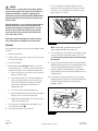
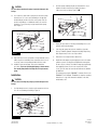
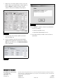
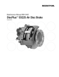
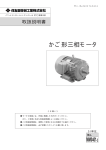
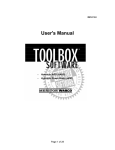
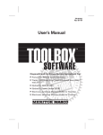
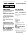
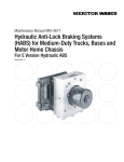
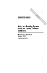
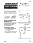
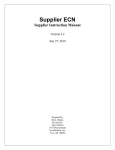
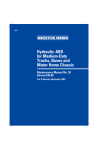
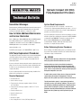
TP-0673
Issued 08-06
Hydraulic Compact Unit (HCU)
Pump Replacement Procedure
Issued
1TP-0673
Technical
08-06
Bulletin
Technical Bulletin
Hazard Alert Messages
System Bleed Requirements
Read and observe all Warning and Caution hazard alert messages in
this publication. They provide information that can help prevent
serious personal injury, damage to components, or both.
If you are replacing the front or rear pump — and the lower
reservoir is not completely drained during the procedure — it is not
necessary to bleed the system. If the reservoir is drained during the
procedure, you must bleed the system.
How to Obtain Additional Maintenance
and Service Information
Refer to Maintenance Manual MM-0401, Meritor WABCO Hydraulic
Power Brake (HPB) System. To obtain this publication, call
ArvinMeritor’s Customer Service Center at 800-535-5560. Meritor
WABCO publications are also available on our website:
If you are replacing the relay valve as well as the pump(s), you must
bleed the system after completing the replacement. Meritor WABCO
recommends using TOOLBOX™ Software to perform the bleed.
Refer to Meritor WABCO Maintenance Manual MM0401 or
Technical Bulletin TP-0672, HPB Relay Valve Replacement
Procedure, for complete bleed procedures.
www.meritorwabco.com
Before Performing Service Procedures
For OnTrac dealer support, call 1-866-ONTRAC-1 (668-7221).
Before working on the HPB braking system, you must depressurize
the system. Depressurization instructions are outlined under Step 4
of Removal on page 2 of this bulletin.
HCU Pump Replacement Procedures
This publication provides instructions for the removal and installation
of the HCU pump(s). Please read these instructions completely
before attempting to service the system and carefully follow all
outlined procedures.
If you are reusing the existing relay valve and are replacing the front
pump, it is not necessary to remove the master cylinder brake lines
in order to access the pump plug on the bottom of the hydraulic
compact unit (HCU).
If you are replacing both the front and rear pumps, install the first
pump before removing the second pump.
Required Equipment
앫 Denatured alcohol
앫 Lint-free tissues or rags
앫 Torque wrench, clicker-type capable of 69 ± 3.54 in-lb
(7.8 ± 0.4 N폷m)
앫 Torque wrench, clicker-type capable of 194.7 ± 17.7 in-lb
(22 ± 2 N폷m)
앫 4 mm hex-head socket
앫 6 mm hex-head socket
앫 Drive ratchet
앫 Needle nose pliers
앫 Hose clamp pliers for ¾-inch (19.5 mm) rubber hose
WARNING
To prevent serious eye injury, always wear safe eye protection
when you perform vehicle maintenance or service.
Park the vehicle on a level surface. Block the wheels to
prevent the vehicle from moving. Support the vehicle with
safety stands. Do not work under a vehicle supported only by
jacks. Jacks can slip and fall over. Serious personal injury and
damage to components can result.
To avoid serious personal injury, release all pressure from the
system before you remove any components. Failure to
depressurize the system may result in serious personal injury.
The full power brake system is a pressurized system that
achieves pressures up to 2320 psi (160 bar). This pressure is
not reduced by switching the ignition off or removing battery
power. Prior to servicing this system, the depressurization
procedures must be performed exactly as presented. Failure to
depressurize the system may result in personal injury or
death.
7.
CAUTION
The HPB system is a complex device that provides optimum
efficiency and operation. If the system sustains damage, or a
component malfunctions and requires replacement, the
replacement procedures provided by Meritor WABCO must be
followed exactly with the associated steps performed in the
order presented.
Use hose clamp pliers to clamp the rubber hose at least
three-inches (76.2 mm) away from the entrance to the HCU
reservoir. Use care to avoid damage to the plastic reservoir
nipple inside the hose. Figure 1.
Figure 1
Hydraulic brake fluid is a caustic substance. Contact with the
hydraulic brake fluid can cause skin irritation. Do not let
hydraulic brake fluid touch any painted surfaces, as it will
remove the paint. Hydraulic brake fluid may also damage
certain non-metal surfaces. Do not let fluid contact brake
pads, shoes, rotors or discs.
Before disposing of used components, verify the warranty
status. Contact OnTrac at 866-668-7221 for instructions.
4006216a
Figure 1
Removal
NOTE: Avoid bending or kinking the brake lines while
disconnecting and handling other components.
Before removing the pump, ensure the replacement pump is readily
accessible.
1.
Wear safe eye protection.
2.
Park the vehicle on a level surface. Block the wheels to prevent
the vehicle from moving.
3.
Disconnect the battery.
4.
Apply the brake pedal a minimum of 30 times to decrease
pressure in the system. To ensure the system is depressurized,
perform the following check on both the front and rear axles.
A.
Remove the protective cover from the end of the bleeder
fitting on one brake caliper.
B.
Attach a bleeder bottle hose to the bleeder fitting at the
wheel end. Submerge the free end of the bleeder hose
into the bleeder bottle. Both the tubing and container
must be able to withstand the chemical effects of
hydraulic brake fluid.
C.
Use a wrench to open the bleeder fitting screw.
D.
Apply and hold the brake pedal down until no more brake
fluid runs out. Do not release the brake pedal.
E.
With the brake pedal still applied, use a torque wrench to
close the bleeder fitting screw.
5.
Use a torque wrench to tighten the bleeder fitting screw to
34.7-39 in-lb (4-4.5 N폷m). @
6.
Repeat Step 4 and Step 5 for the other axle.
8.
For a rear pump, proceed to Step 9. For a front pump, carefully
remove the relay valve from the HCU to gain access to the
pump. Do not kink or bend the brake lines while removing
the relay valve.
9.
Prepare the replacement pump. Lubricate both pump O-rings
with brake fluid. Actuate the pump several times by depressing
the spring-loaded pump button by hand. The initial force
required to actuate the pump and depress the pump button
may be high at first. However, after the first actuation, the force
should be reduced.
10. Use a 6 mm hex-head socket wrench to remove the pump
retaining plug from the HCU cavity. To minimize fluid spill, keep
the replacement pump within reach and prepared for
installation. Figure 2.
Figure 2
4006203a
Figure 2
TP-0673
Issued 08-06
Page 2
Copyright ArvinMeritor, Inc., 2006
(16579/22882)
Printed in USA
2.
CAUTION
Use care when removing the pump to prevent damage to the
O-rings.
Insert the pump retaining plug into the threaded hole. Use a
6 mm hex-head socket wrench to tighten the plug to
195 ± 18 in-lb (22 ± 2 N폷m). Figure 5. @
Figure 5
11. Use needle nose pliers with a good grip to remove the pump
from the bore. Use care to prevent damage to the O-rings.
Avoid sliding the needle nose pliers on the pump. This can
produce metal filings or contaminants which can enter the
pump bore. Do not leave any foreign material in the pump
bore. Figure 3.
Figure 3
4006206a
Figure 5
3.
Repeat the procedure for removing and installing the second
pump (if replacing both pumps).
4.
If the front axle pump was replaced, install the relay valve.
Refer to TP-0672, Hydraulic Compact Unit (HCU) Pump Relay
Valve Replacement, for the correct procedures.
5.
Remove the hose clamp from the rubber hose.
6.
Install a bleeder adapter cap, and apply pressure to the master
cylinder reservoir. Use filtered and regulated air and regulate
the air to 35 psi (2.4 bar). The fluid level may drop significantly
after applying pressure as the lower reservoir fills. If this
occurs, pressure must be removed and fluid must be added to
the MAX level.
4006204a
Figure 3
12. Inspect the bore holes to verify that no foreign material such as
rubber, rag lint or metal filings have entered the bore holes. If
necessary, remove foreign material with a lint-free swab.
13. Install the replacement pump. Refer to the installation
procedure. If you are replacing both pumps, do not remove
the second pump before installing the first replacement
pump.
The following steps require TOOLBOX™ Software. Refer to the
TOOLBOX™ User’s Manual, TP-99102, for complete operating
instructions. A copy of this manual is available on the web,
meritorwabco.com.
Installation
CAUTION
Use care when installing the pump to prevent damage to the
O-rings.
1.
Use light hand pressure to slowly seat the pump into the bore.
Use care not to damage the O-rings. Figure 4.
Figure 4
4006205a
Figure 4
(16579/22882)
Printed in USA
Copyright ArvinMeritor, Inc., 2006
TP-0673
Issued 08-06
Page 3
7.
With pressure on the master cylinder reservoir, reconnect the
batteries. After reconnecting the batteries, turn the ignition on.
Connect TOOLBOX™ Software to the vehicle. Use this
software to verify pressure is building correctly. Figure 6.
Figure 8
Figure 6
Figure 8
1222
1438
4006207a
10. Use TOOLBOX™ Software to verify correct system function.
Check for the following:
앫 System Pressure (Main Screen)
앫 System Faults (Fault Information Screen)
Figure 6
8.
Remove pressure from the master cylinder reservoir and
remove the adapter cap.
9.
After the accumulators have fully charged, approximately
2100 psi (145 bar), deplete the system pressure. Under the
EOL menu on the HPB screen, select Deplete Accumulators.
Figure 7 and Figure 8.
11. Record, then repair, any new fault occurrences. Clear the
system faults.
Figure 7
4006208a
Figure 7
Meritor WABCO Vehicle Control Systems
2135 West Maple Road
Troy, MI 48084-7121 USA
800-535-5560
meritorwabco.com
Information contained in this publication was in effect at the time the publication was approved for printing and is subject to
change without notice or liability. Meritor WABCO reserves the right to revise the information presented or to discontinue the
production of parts described at any time.
Copyright 2006
ArvinMeritor, Inc.
All Rights Reserved
Printed in USA
TP-0673
Issued 08-06
(16579/22882)