1
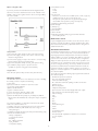
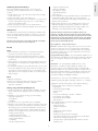
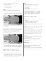
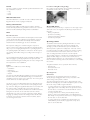
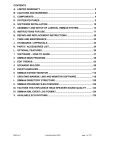
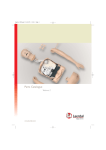
SimMan
Directions for Use
www.laerdal.com
Cautions and Warnings
1. Reorienting or relocating the receiving antenna.
2. Increasing the distance between the device and receiver.
3. Connecting the device to an outlet on a circuit different from
that to which the receiver is connected.
4. Consulting the dealer, or an experienced radio/TV technician,
for help.
Laerdal SimMan should be operated by trained personnel.
Do not introduce fluids into the torso area or left (BP) arm of the
manikin, as electronic components may become damaged.
Clean with mild soap and water. DO NOT SUBMERGE MANIKIN.
Latex
The veins in the IV Arm, and Pneumothorax bladders contain latex.
Users who suffer from latex allergy should take precautions while
using or handling the latex parts by wearing non-latex protective
gloves.
Use on clean surface only. AVOID FELT TIPPED MARKERS, INK
PENS, ACETONE, IODINE OR OTHER STAINING MEDICATIONS, AND PLACING THE MANIKIN ON NEWSPRINT OR
INKED LINES OF ANY KIND.
Students should wash their hands prior to using the simulator and
wear gloves when using the simulator. Treat SimMan as you would
a real patient.
Limited Warranty
Use of a defibrillator for training purposes represents an operational
hazard equivalent to use of a defibrillator on a real patient since it
involves the release of high levels of electrical energy into the
training manikin. Consequently:
All safety precautions for use of defibrillators must be followed, as if
the manikin were a patient. Consult your defibrillator's User Manual.
• Defibrillation should be performed on the defibrillation
connectors only. If defibrillation is performed over one or more
of the ECG connectors, high voltages may be present on
the remaining connectors during the shock.
• To prevent overheating, do not provide more than three (3)
defibrillator discharges (max 360J) in a sequence. Do not exceed
an average of two (2) defibrillator discharges per minute during
the training session.
• The manikin must not be in contact with electrically conducting
surfaces or objects during defibrillation. A flame supporting
atmosphere, for example with a high content of oxygen, should
be avoided during defibrillation.
• The manikin chest must be kept dry. Special attention should be
taken when using IV Arm, Urinary system or Bleeding Control
Modules.
• To prevent chest skin electrode pitting, do not apply conductive
gel or conductive defibrillation pads intended for patient use.
• Do not use cables or connectors having visible damage.
• Do not spill fluids over any component inside the manikin torso,
since this could damage the unit and might also present a possible
hazard for the operator.
• If a training session involves the administration of fluids and/or
drugs into the IV arm, empty the arm immediately following the
training session.
• Do not allow the manikin's skin to come in direct contact with ink
or photocopied paper, as this can permanently stain the skin.
Avoid using colored plastic gloves when handling the manikin,
as they may also cause discoloration.
• Do not introduce any fluids (except airway lubricant in small
amounts to lubricate the airway) into the esophagus or trachea
of the manikin.
Please refer Laerdal Global Warranty or see www.laerdal.com
Approvals:
The product is CE-marked and in compliance with
essential requirements of council directive 89/336/EEC;
EMC – directive.
This device generates, uses and possibly radiates radio-frequency
energy. If it is not installed and used in accordance with the
instructions, it may cause harmful interference to radio communications. In that case, the user is encouraged to attempt correction of
the interference by:
2
CAUTIONS AND WARNINGS . . . . . . . . . . . . . . . . . . . . . . . . . .2
INTRODUCTION . . . . . . . . . . . . . . . . . . . . . . . . . . . . . . . . . . . . 3
ITEMS INCLUDED . . . . . . . . . . . . . . . . . . . . . . . . . . . . . . . . . . . . 4
GETTING STARTED . . . . . . . . . . . . . . . . . . . . . . . . . . . . . . . . . . 4
IN USE . . . . . . . . . . . . . . . . . . . . . . . . . . . . . . . . . . . . . . . . . . . . . . 7
MAINTENANCE . . . . . . . . . . . . . . . . . . . . . . . . . . . . . . . . . . . . . 11
TROUBLESHOOTING . . . . . . . . . . . . . . . . . . . . . . . . . . . . . . . . 13
TECHNICAL DATA . . . . . . . . . . . . . . . . . . . . . . . . . . . . . . . . . . 13
PARTS / ACCESSORIES LIST . . . . . . . . . . . . . . . . . . . . . . . . . . . 14
Introduction
SimMan is a full body, adult manikin that allows the simulation of
Basic and Advanced Life Support Skills and Assessment to develop
both individual and team skills.
The simulator allows observation and recognition of most vital signs
which are used in emergency medicine either directly on the
manikin itself or on the included simulated Patient Monitor. When
used correctly, these features will support the students’ competence
ability to reach the correct diagnosis based on active observation as
opposed to being prompted by instructor cues.
The patient monitor also doubles as display for other functions, such
as display of 12-lead ECG and X-rays.
The manikin allows for most relevant medical intervention to be
performed according to their medical guidelines and protocols. The
Laerdal SimMan contains an advanced airway allowing for simulation
of difficult airway management cases. The anatomy can be changed
during the scenario (via remote control) to indicate changes to the
patient condition or as a response to students’ intervention. Correct
form and technique are required to perform direct laryngoscopy
and endotracheal intubation. Correct use of a variety of airway
adjuncts will successfully ventilate the patient simulator.
SimMan is delivered with a set of normal pupils inserted in the
head's eye sockets and a separate case containing 3 sets of replacement pupils (normal, constricted, dilated) for simulation of various
medical conditions.
The simulated patient monitor is a replication of the Philips
IntelliVue patient monitor, which includes the ability to set up the
screen layout in various ways. It also allows configuration outside
the IntelliVue’s features to mimic other patient monitor types as
well.
SimMan is operated through a Software (SW) which runs on a PC.
Interaction with the SW is done through a Graphical User Interface
(GUI) where the various vital signs parameters are changed directly
or through pre-programmed scenarios. The SW also allows
automatic and manual logging of scenario events as well as video
capture. The events logged during a scenario can be shown in a
debrief viewer together with video capture. The log is synchronized
with the video capture. This allows the instructor to review both
the log and actual performance during debriefing. The debrief can
also be stored for later review.
3
ENGLISH
Contents
Items included
Connection Cables and Tubing
(may vary depending upon configuration):
- Cable, Link Box to Manikin (15 pin)
- Cable, Link Box to PC (9 pin)
- Cable for Sounds, PC to Link Box
The Laerdal SimMan includes the following main components:
-
-
-
-
Laerdal SimMan Manikin
SimMan Software CD-ROM
Directions for Use
SpO2 (Pulse Oximetry Probe)
Set of Defibrillation Studs:
Hands Free Defibrillation/Pacing Adaptors
(Heartstart and Physio Control)
Plates for Manual Defibrillation
Replaceable Neck Skin Collars (6)
Roll of Crico-Thyroid Membrane Hy-Tape (2)
Chest Tube Insertion Modules (6)
Interchangeable pupil set [case containing 3 pairs of pupil inserts
(normal, constricted, dilated)]
Airway Lubricant
Upper Dentures
[one (1) non-breakable installed, and (3) breakable]
Replaceable Male and Female Genitalia
with Urinary Connection Valves
Tank Thigh Hardware Kit
Tool Kit, consisting of:
- Pliers
- Screw-driver
- Nut Driver
- Bolts for attaching optional wound modules to the body
Maintenance/Repair Kit, consisting of:
- Extra Pneumothorax Bladders
- Modeling Wax
- Talcum Powder
IV Kit, consisting of:
- Blood Bags with IV Tubing (2)
- Simulated Blood Concentrate
Hose, Manikin Air and CO2 Supply
Blood Pressure Measuring Kit
Track Suit (jacket and trousers)
Additional items purchased separately
- Pressurized Air and CO2 source (Compressor Unit
or Regulator Unit)
Getting started
To use your SimMan, carefully follow the instructions provided in
the “Install Guide” (found in the peripheral box) and this document.
Some configurations are delivered with pre-installed software.
If your system is not pre-installed, pay close attention to software
set-up. Your SimMan will not operate correctly if the software is
not properly installed.
Attaching the Legs:
1) Remove the belly by pulling gently on the bottom and place it
aside.
2) Remove the bag from the leg.
3) Remove the cardboard packing tube from the threaded steel
tube protruding from the upper end of the thigh.
Caution: Do not allow tape or packing to pull on the wire or
air tube extending from the steel tube.
4) Open one Tank Thigh Hardware Kit (1008080) and place the
hardware in a convenient spot.
5) Gently feed the electrical wire and plastic air tube through the
pelvis hole and into the pelvic cavity.
6) Push the steel tube on the thigh as far as possible through the
hole and into the pelvic cavity.
DO NOT PULL THE LEG BY THE ELECTRICAL WIRE
OR PLASTIC AIR TUBE
7) Slide the flat washer from the hardware kit over the wire, air
tube, and steel tube.
8) Slide the spring from the hardware kit over the wire, air tube,
and steel tube.
9) Slide the thumb nut from the hardware kit over the electrical
wire first, and then over the air tube.
10) Holding the thigh in a convenient position, thread the thumb
nut onto the steel shaft until the feel of the hip articulation is
satisfactory.
11) Attach the thigh air tube to the open connector on a similar air
tube in the pelvis. Right leg tube goes to the tube on the right
side, and left goes to left.
In addition, some configurations contain the following:
- Laptop computer
- USB Camera
- Simulated Patient Monitor
- USB Hub
- PDA
- Link Box
4
Air and CO2 Source (optional)
Option 1: Compressor Unit
If you have purchased Laerdal SimMan with a Compressor Unit,
attach one end of the double lumen tube into the compressor and
the other to the right axillary side of the manikin.
Link Box
The Link Box connects the manikin to the computer.
1) Attach manikin cable to right lower side of manikin’s torso and
to the connector marked “Manikin” on the back of the Link Box.
2) Connect serial cable to connector marked “PC” on the back of
the Link Box and to serial port on back of your computer.
3) Connect clear tubing from blood pressure cuff to the inlet
marked “BP cuff” on the back of the Link Box.
4) Connect the SpO2 cable to the SpO2 connector on the back
of the Link Box.
5) The audio cable has three ends. Connect the RCA / phono plug
to the connector marked "Audio input" on the back of the link
box. The stereo jack with single wire shall be connected to the
Simulated Patient Monitor, and the stereo mini jack with double
wire shall be connected to the computer's headphone output.
For illustrations please see the accompanying Install Guide.
If a wireless microphone is used, the receiver should be
connected directly to the Link Box connector marked "Audio
input" instead of the audio cable described above (pre-defined
vocal sounds will not be possible to use in parallel)
6) Plug the Link Box AC power cable into a power supply
(110-240 V AC). If you are using the Portability Kit, attach to
the 12 V DC input according to the Portability Kit instructions.
7) Connect external speakers, if used, to connector marked
"Ext. speaker" on the back of Link Box.
Start procedure:
1) Check that Power switch (4) is set to off position “0”.
2) Plug power supply cable into plug (5) in Compressor panel.
3) Plug power supply cable into power source.
4) Connect CO2 supply to the “Input CO2” connector using
the black hosing attached (optional feature).
5) Check that Drain valve (1) is closed.
6) Close Air valve (2) and CO2 valve (3)
7) Push Power switch (4) to on position “1”, the Compressor will
start and run for approx. 45 seconds to build up pressure in tank.
8) When Compressor stops, you can start to use the manikin.
Open the Air valve (2) and the CO2 valve (3).
9) The Compressor will start and stop with different intervals
depending on consumption of air.
USB Hub
A USB hub is supplied with the system to provide additional USB
ports. Connect the USB Hub to one of the USB connectors at the
back of the PC. Attach the AC adapter to the USB Hub and to a
wall outlet (110 or 230-240V AC).
SpO2 Probe
The SpO2 finger probe provides enhanced realism for the care
provider by simulating the use of an actual pulse oximetry probe.
When the probe cable is connected to the Link Box, SpO2 will not
be displayed until the probe is placed on one of the manikin’s
fingers (means that “light” is blocked). If the probe is not attached
to the Link Box, SpO2 will only be displayed automatically when
selected by the operator through the instructor panel on the PC.
Stop procedure:
1) Push Power switch (4) to off position “0”, the Compressor will
stop if it is running.
2) Close Air valve (2) and CO2 valve (3).
3) Open Drain valve (1) and drain air out of system.
Blood system
The blood system includes a blood bag with tubing that can be
connected to the veins and be altered by varying the elevation of
the blood bag.
Warning:
Do not open Compressor box when energized, dangerous voltage inside.
Only to be opened by authorized personnel.
Important:
If the Compressor Unit is stopped manually with the on/off switch, the
air tank must be drained before restart.
5
ENGLISH
12) Attach the thigh electrical connector to the open mating
connector in the pelvis. Right leg wire goes to the wire on the
right side, and left goes to left.
13) Repeat with the other leg.
14) Gently replace the belly.
To remove leg(s), reverse the procedure.
Option 2: Regulator Unit
e) Auscultation sounds
- Lung
- Heart
- Bowel
f) Vocal sounds
- Numerous vocal sounds are available (moan, vomit, cough, etc.)
- Additional sounds can be recorded by the user
- Microphone option (instructor may speak directly through
the manikin’s head speaker by using a microphone)
g) Left/right or bilateral lung obstruction
h) Pulse strength
i) Activity Log
j) Scenario Builder
k) Trend Editor
l) Event Handler
m)Debriefing including activity log synchronized with video
and monitor pictures
If you have purchased Laerdal SimMan with the Regulator Unit,
attach one end of the double lumen tube to the “Air/CO2 out to
Manikin” outlet on the regulator and the other to the right axillary
side of the manikin.
PDA remote control
A personal digital assistant or PDA is used as the remote control.
The PDA communicates with the software via Bluetooth. A PDA
User Guide is included in the peripheral kit. Refer to this guide for
additional information.
Simulated Patient Monitor
The Simulated Patient Monitor is connected to the PC (laptop). It is
a touch screen monitor that provides concise clinical feedback of
physiological parameters. All parameters are instructor-activated
with the ability to set a lower and higher alarm limit for every parameter shown on the monitor. The monitor may be configured to
display the desired parameters and curves and it is possible to save
and retrieve five (5) configurations. Colors and curve trace speeds
can also be changed. The CO2 curve has by default a slower trace
speed. Because all information is simulated rather than actual, the
parameters, with the exception of ECG, cannot be “measured or
displayed” on clinical equipment. For additional information, refer to
the software helpfiles.
The monitor provides the following output (synchronized with all
other clinical outputs)
- Arterial blood pressure waveform
- CO2 and capnograph waveform
- Heart rate related to SpO2
- BP – with timed automatic updating and ‘BP now’ function
- Respiratory rate
- Blood Temperature
- Peripheral Temperature
- SpO2 waveform and numerical display with audio output
- CVP waveform and numerical display output
- PAP and Wedge
- TOF
- TOF%
- CO
- inO2
- inN2O
- in Anesthetic Agent
- etCO2
- etN2O
- et Anesthetic Agent
- Monitor trends
- 12-lead ECG with adjustable ST-elevation and conduction
on some rhythms
- X-ray
Start procedure:
1) Close Air valve (Shut off Air) and CO2 valve (Shut off CO2).
2) Connect Air supply (5-8 bar) to the “Air in” connector using
the blue hosing attached.
3) Connect CO2 supply (4-6 bar) to the “CO2 in” connector using
the black hosing attached (optional feature).
4) Open Air valve (Shut off Air) and CO2 valve (Shut off CO2).
5) Jet ventilation (TTJV) requires a special connector
(available for purchase using part number 381201).
Stop procedure:
Close Air valve (Shut off Air) and CO2 valve (Shut off CO2).
Operating software
The SimMan Software serves as the instructor's tool for controlling
the training scenario. It requires the following:
a) Type; Dell
b) Processor: Minimum Pentium M 1,8 GHz or better
c) Hard drive: 60 GB minimum
d) RAM: 512 MB minimum
e) System : Windows XP Pro
f) Screen: Dual Screen with min. 1280 x 1024
g) Mouse: Two (2) button scroll wheel mouse
h) Other: CD-RW, RS-232 (serial port), 2-4 USB ports, Built-in
Ethernet LAN, Internal Bluetooth, Microphone input, Headphone
output
For software installation, see instructions included in the Install
Guide. The software features are:
a) Training controls via computer keyboard, mouse and/or PDA
b) Extensive ECG library with variable rates and a range of
extrasystole types
c) Variable pacemaker threshold (external pacemaker training only)
d) Control of manikin functions
- Airway complications
- Tension Pneumothorax
- Breathing
- BP - NIBP and Arterial
- SpO2 simulation
- Temperature display
6
- Surgical cricothyroidotomy
- Retrograde intubation
- Fiberoptic procedures
- Light Wand intubation
- Bronchoscopy
e) The manikin has two lungs. Intubation that is too deep will result
in unilateral lung filling. This usually occurs on the right side,
due to the accurate anatomical modeling of the tracheobronchial
junction and bronchial tree.
f) When airway adjuncts are used, ventilation may be made more
difficult by activating decreased lung compliance for either the
right lung or left lung. Activating decreased lung compliance for
both lungs causes airway adjuncts to fail to ventilate.
USB Camera
The USB Camera provides enhanced debriefing possibilities. Video
input is synchronized with the SimMan scenario log. To set-up the
camera, see Install Guide and Directions for Use included in your
camera packaging.
Important: Mouth-to-mouth/nose/mask ventilation should not be
performed on SimMan. The upper airways must be thoroughly cleaned
and the lungs changed if these techniques are performed on the manikin.
Important: Prior to using airway adjuncts, spray the inside of the pharynx,
nostrils and all airway management devices to be inserted with a liberal
amount of the provided airway lubricant.
Important: Connect the camera via a USB port directly on the laptop.
Do not use the hub as this may cause interference.
Airway Adjuncts – Sizing and Precautions :
ET Tubes - While ET tubes as large as 8.5 may be used, we recommend the use of ET tube size 7.5 to extend the life of the simulator.
We also recommend the use of a malleable stylette. Care should be
taken that the stylette does not extend beyond the end of the tube,
as with any direct intubation.
Laryngeal Mask Airway (LMA) - The Laerdal SimMan will allow use of
the LMA Classic, LMA Unique and LMA Fastrach. Although a #5 LMA
may seal correctly, the airway has been designed for use with a #4
LMA.
In use
Head
a) The head allows for performance of head tilt and jaw thrust
maneuvers; however, the airway is open in all positions.
b) A speaker located in the head allows the instructor to speak
through the SimMan (to simulate a patient) or use pre-defined
vocal sounds.
c) Upper dentures are replaceable. Soft/non-breakable dentures are
pre-installed but can be replaced by a rigid/breakable version for
more realism.
d) To change the pupils: Open the eyelids wide, take care not to rip
the face skin. Using the suction cup provided or the edge of your
finger nail, remove the pupil from the eye socket. Replace with
the pupil of your choice, using the suction cup or press into place
with your finger.
CombiTube - The Laerdal SimMan will allow the use of the
CombiTube, as it will successfully ventilate the “patient”. We
recommend the use of the CombiTube trainer, as it will generally
withstand multiple uses. The CombiTube trainer is sized the same as a
large adult CombiTube. Although a small adult size CombiTube may
work with varying success, the CombiTube trainer provides more
cost-effective training and reliability of function.
Neck
a) Bilateral carotid pulses.
b) Airway access through simulated crico-thyroid membrane.
c) Decreased Cervical Range of Motion - DCROM
(instructor-controlled).
The instructor can cause any of the ventilation procedure to fail to
ventilate by setting both right and left lung “resistance” to “complete”.
g) Using the computer user interface or the PDA, the following
airway functions may be activated and deactivated:
- Laryngospasm
- Posterior Pharyngeal swelling
- Tongue edema
- Trismus
- Decreased Cervical Range of Motion - DCROM
- Can’t Intubate, Can Ventilate
- Can’t Intubate, Can’t Ventilate
- Verbal response
h) The manikin simulates spontaneous respiration with
the following features:
- Chest rise and fall
- Variable breathing rate
- Apnea
- Variable pulse oximetry display
- Exhalation of air
- Exhalation of CO2 (instructor-controlled)
- The variable respiratory rate is synchronized to the Simulated
Patient Monitor display and lung sounds
- The tidal volumes dynamically alter in line with the selected
respiratory rate
Airway, Lungs and Airway Management
a) The airway is instructor-controlled to allow simulation of various
airway complications, including the failure of therapeutic airway
devices.
b) Ventilation can be performed using any of the following:
- Bag-Valve-Mask devices
- Jet ventilation
- Ventilator
c) The system does not accept PEEP modes of ventilation.
d) SimMan accepts a wide range of airway management devices and
techniques. Correct form and technique are required to perform
direct laryngoscopy and endotracheal intubation. Correct use of
a variety of airway adjuncts will successfully ventilate the patient
simulator. Some examples are (see notes below for information
on sizing and precautions):
- Oral/nasal pharyngeal airways
- Endotracheal tubes - nasal and oral
- Laryngeal Mask Airways
- CombiTube
- Needle cricothyroidotomy
7
ENGLISH
Calibrating the Patient Monitor
Because the Simulated Patient Monitor uses touch-screen
technology, it must be calibrated before use. To calibrate the
monitor:
a) Double click the “elo” logo in the system tray in the lower right
corner of the screen.
b) Click on the “Align” button in the dialog box.
c) If target indicators appear first on the instructor computer screen
and not on the patient monitor, press “Esc” or wait until they
appear on the patient monitor.
d) Touch each target as it appears on the Patient Monitor.
e) Touch the green check mark after all targets have been touched.
i) Through the operating SW, the instructor can activate
respiration complications like:
- Pneumothorax
- Breath sounds
- Decreased right and/or left lung compliance
- Stomach Decompression
Pulses
a) SimMan has physiologically correct palpable pulses:
- Bilateral carotid pulse
- Bilateral Dorsalis Pedis and Posterior Tibal pulses
- Bilateral femoral pulse
- Left radial pulse
- Left brachial pulse
b) The pulses are synchronized to the simulated ECG and,
when activated, the external pacemaker upon capture.
c) The pulse strength is dependant on the selected blood pressure,
but the strength of peripheral pulses can also be manually
controlled to simulate a wider range of clinical conditions.
d) Pulses, once activated, will remain on for approximately
five (5) seconds before reactivation is required.
Torso
a) Anatomically modeled from a human specimen, the torso
demonstrates normal anatomical surface landmarks.
b) SimMan has correct anatomical landmarks for external chest
compressions. Chest compressions will produce carotid pulses,
as well as compression artifacts on the Simulated Patient Monitor.
Important: Care should be taken when palpating pulses. Use of
excessive force results the inability to feel pulse.
Pneumothorax
a) Tension pneumothoraces can be simulated through the inflation
of resealable bladders. Needle decompression can be
performed at:
- Bilateral mid-clavicular line, 2nd intercostal space
- Right mid-axillary line, 5th intercostal space
b) Chest tube insertion can be simulated, and exploration and cut
can be made at left mid-axillary line at (4th and) 5th intercostal
space.
ECG sites
c) Manikin is equipped with separate defibrillation and ECG
monitoring connectors. The system provides 3-lead ECG readings
(4 connectors).
Important: We recommend a 22 (or smaller) gauge needle for decompression of the chest. Using a smaller gauge needle increases the longevity of the chest skin and bladders.
Caution: The ECG connectors are designed for ECG monitoring only. If
defibrillation is attempted over any of the ECG connectors, high voltages
may be present on one or more of the uncovered connectors during the
shock. (See the "Cautions and Warnings" section.) Defibrillation
attempts via the ECG connectors will also damage the internal
electronics requiring that they be replaced.
The Chest Tube insertion module is located at the left mid-axillary
site. This module allows chest tube insertion to be performed. A cut
can be made at left mid-axillary line at the (4th and) 5th intercostal
space. To replace the used Chest Tube insertion module, simply
remove from its location and add a new one with the opening
positioned toward the shoulder.
Insert Pads
a) SimMan contains a left thigh pad, gluteal , gluteal, ventro-gluteal
and right deltoid insert pads.
b) The pads can be used for intramuscular and subcutaneous
injection practice.
c) These can be interchanged with optional trauma or nursing
wound modules.
Defib sites
IM/SC Injections
The insert pads are foam filled and can be injected with fluids. The
foam is removable and should be squeezed out (like a sponge) and
allowed to air dry immediately following the practice of these
procedures. Powdering foam pads with talcum powder eases
reinsertion into the skin.
There are four sites for subcutaneous and intramuscular injections,
including right deltoid, gluteal, left thigh, and ventro-gluteal. Using a
22 gauge (or smaller) needle increases the longevity of the "skins".
d) Manikin is equipped with two defibrillation connectors. ECG
signal can also be monitored across these connectors. Instructor
can, via appropriate keyboard or remote control, command/select
the “Ignore Defib” function. This determines if the defibrillation
shock results in conversion to a selected waiting rhythm. Manual
paddle adapters are supplied for use with manual defibrillators.
Caution: Defibrillation must be performed only over the two
defibrillation connectors. (See the "Cautions and Warnings" section.)
e) Connectors for external pacing are connected to the manikin’s
defibrillation connectors. Patient pads should not be used, as they
do not guarantee sufficient contact. The system has a variable
pacing threshold and the ability to “ignore” pacing. Pacing capture
results in a pulse synchronized with the heart rate and the display
of a paced rhythm on the Simulated Patient Monitor.
8
Procedure for filling Blood Bag (IV Bag):
Use a syringe to inject fluid into IV bag, and fill to desired level.
Control flow of blood into arm, via clamp.
Abdominal distension
Abdominal distension occurs with excessive ventilation while using
Bag-Valve-Mask or if the esophagus is intubated.
Urinary catheterization
Interchangeable realistic genetalia make it possible to simulate
female and male patients. The genetalia is connected to a reservoir
which can be filled with liquid during simulated catherization.
Air and CO2 Source
Compressed air is provided by a compressor or other type of pressurized air source via a regulator unit, allowing many functions to
take place:
- Airway complications
- Spontaneous breathing
- Tension pneumothorax inflation
- Carotid and pedal pulse
Arms
Blood Pressure Arm
Left Arm is a BP Arm with radial and brachial pulses and Korotkoff
sounds. The BP arm allows palpation and auscultation of a blood
pressure that can be measured automatically on the Simulated
Patient Monitor. Auscultation gap can also be simulated.
Operating software
The SimMan SW is started by clicking the SimMan icon on the
computer desktop. After entry of password (optional) and
selecting a profile, the SimMan starts up in the default mode
which represents a patient in a healthy state. If the web camera
recording is enabled, you will be prompted to start the recording.
For more information on this feature, refer to the section on
video recording later in this document or to the help files.
The operating software is controlled via a Graphical User Interface
(GUI). The GUI displays an overview of the current status of
simulated patient’s vital signs, the control functions for modifying
these, and a time-based log of the events which has occurred during
the scenario.
Blood pressure settings are controlled using the computer or
remote control. These settings are also linked to the ECG functionality, so if you are changing the rhythm from a perfusing rhythm to a
non-perfusing rhythm, this will also be reflected on the blood pressure settings, which will be changed according to the new type of
rhythm.
A non-perfusing rhythm will also change breathing rate (BR) to zero.
When changing to a perfusing rhythm, the blood pressure will
remain at 0/0 until changed; breathing rate can not be changed until
blood pressure has been established.
The patient simulator can be operated in three manners;
- Manual mode,
- Semi-automatic mode
- Automatic mode
IV-Arm
Right Arm is a Multi-venous IV Arm allowing:
- Cannulation
- Phlebotomy
- Drug administration
- Infusion
The veins are self-sealing allowing multiple uses; however, repetitive
insertions in the same area will result in leakage sooner than if the
cannulations had been spread over a wider area. The venous system
and the skin sleeve are both replaceable.
Operating Modes
Manual mode
In manual mode the vital signs parameters are changed
directly through changing the values one-by-one based on the
desired change of the patient condition.
The various vital signs parameter can be changed directly on the
GUI in the following ways. For detailed description, please see help
files under “Help” in GUI’s Program Menu Bar.
- To change values in the “Instructor Monitor Control Center”
(upper right corner of the GUI); click on the parameter and set
the new values, or rotate the mouse wheel while the cursor is
over the numerical values.
- To change values in the “Airway and Circulatory Control
Center” (center section which includes a torso illustration), by
click directly on the parameter which is to be changed and select
the new state, or use the slider bars.
- To change values in the “Respiratory Control Center” and
“Difficult Airway Control Center” (upper left corner) select
state or use the slider bars.
The IV arm can be used with simulated blood by attaching the supplied IV bag tubing to one of the two latex vein openings near the
top of the arm. Using the supplied simulated blood concentrate, mix
the desired volume of simulated blood and add to the IV bag
(see procedure below). Release simulated blood until it runs via the
tubing into the arm and out the other latex vein. Once fluid is
running freely out of the second vein, seal it using a clamp. Using a
22 gauge (or smaller) needle for IV training increases the life of the
IV arm skin. If you want the student to infuse medicines, attach a
second IV bag for free flow.
9
ENGLISH
Sounds
The torso contains a number of hidden speakers that allow the realistic auscultation of sounds:
- Lung
- Heart
- Bowel
Semi-automatic / Automatic mode
In Semi automatic / Automatic mode the change to multiple vital
signs parameter can be pre-defined as “trends”. These trends can
then be activated one-by-one directly or multiple activated via
the “event handler” function. Trends allow the instructor to
introduce physiologic situations into the simulation. A brief overview
is shown below, for more information refer to the help files.
To create a new scenario:
1. Choose “Start Scenario Editor” from the Edit dropdown menu.
2. Click the new scenario () button
The scenario is constructed from a set of frames. Each frame represents a state of the patient. The scenario can only operate in a single
frame at any given time. The scenario moves to other frames as
events specified in the “Events field” occur. To control which frame
the scenario moves to, connection lines are drawn from each event
box to the desired frame. When the specified event occurs, the
scenario moves to the corresponding frame. For a more detailed
description, refer to the software help files.
To use pre-programmed or saved trends:
1. Select the “Start/Stop…” button located in the Trends box
in the main window.
2. Select the desired trend.
3. Click the start button.
Saving Scenarios
To save a new scenario:
1. Select “File” from the dropdown menu.
2. Select "Save".
3. Enter the name of the scenario.
4. Click the “Save” button.
To build and save new trends:
1. Select “Start Trend Editor” from the Edit dropdown menu.
2. Select the parameter to be included in the physiologic model
of the trend you wish to design.
3. Click “ok”.
To retrieve the file at a later time:
1. Click the “Start Scenario” button on the GUI.
2. Select your saved scenario.
Automatic mode, creating and using scenarios
In automatic mode, scenarios which includes multiple
alternative and consecutive changes to the vital signs can be
pre-defined. The scenarios can be constructed so that the change
from one condition to the next may have multiple outcomes.
The various outcome alternatives have been defined in the scenario
and triggered by pre-defined events. These events may be either
automatically registered events such as “time” or a defibrillator
shock, or by manually entered events such as administration of drugs.
Debriefing during or after a scenario
The debriefing function is available both during and after scenarios.
To activate the debrief view, click on the “Debrief” button. If you
are currently running a scenario, this action will automatically pause
your running scenario and take you to the debrief screen. After you
have reviewed the log, you can choose to save the debrief or return
to the scenario without saving. To exit, select “Exit” from the file
dropdown menu and follow the prompts to save or exit without
saving as desired. If you paused a running scenario, click on the play
( ) button from the main SimMan GUI to resume the simulation.
For more information on the Debrief viewer, refer to the help files.
SimMan is delivered with a set of pre-programmed scenarios.
Pre-programmed or saved scenarios can be started, paused, halted
or debriefed from the “Scenario Control Center” found in the lower
left quadrant of the GUI.
Halting the scenario
When a scenario is running, clicking the halt ( ) symbol will put
the scenario is manual mode. The software will confirm that you
want to stop the scenario. After a “yes” response the word
“Halted” will appear on the screen. The scenario continues to run
but all operations must be carried out manually by the instructor.
To fully stop and save a scenario, click the debrief button. When the
debrief viewer appears, choose “Save As” from the “File” dropdown
menu.
To start a scenario:
1. Click “Start Scenario”.
2. Select a simulation case to run.
To temporarily halt the scenario, click on the pause (II) symbol.
To resume a simulation that has been paused, click on the play ( )
symbol.
To halt a scenario, click on the halt (
) symbol.
Instructor Monitor Control Centre
The instructor can manipulate the values of the monitor parameters
from the Instructor Monitor Control Centre which can be found in
the upper right quadrant of the main GUI. Adjustments can be
made to any of the physiologic values by pointing the mouse over
the desired area and clicking. Windows will open allowing the
instructor to select and apply the desired changes and functions.
Before creating a new scenario, it is important to understand the
difference between Events and Actions.
Events
Things that happen outside of a scenario, usually caused by students,
are called “Events.” The ABC/Miscellaneous/Medication events in the
main window are also called “Scenario Events.” There are also
“Time Events” caused by either of the two timers reaching a predetermined limit
Configuring the Patient Monitor and Simulator and
Creating Profiles
General configurations for both the simulator manikin and patient
monitor can be controlled via the GUI. To configure:
1. Select “Configure” from the “Edit” dropdown menu.
2. Select either the “General” or “Patient Monitor” tab.
3. Double click on the appropriate icon to enter submenus.
4. Make desired changes.
5. Select “ok” to initiate the change.
If you have changed the configuration, the software will ask you
whether or not you wish to save the changed configuration, try it
without saving or cancel the operation. If you choose “yes,” you will
Actions
In a scenario, “Actions” are performed by the scenario.
For example, changing a parameter value, creating an airway
complication and making vocal sounds are “Actions” performed
by scenarios.
10
- Clean with mild soap and water. DO NOT SUBMERGE
MANIKIN.
- Modules and all other parts should be drained and air-dried
thoroughly prior to storage. Disinfectants should be used
when appropriate.
- All subcutaneous and intramuscular injection pads should be
squeezed to eliminate excess water. To prevent mildew and
mold, the foam filling should be soaked in a mild solution of
bleach and water or a 1% Virkon solution. Squeeze the solution
out and allow the filling to air dry prior to reinsertion and storage.
- Articulating parts will benefit from a light application of talcum
powder prior to training sessions.
- Powdering inside of chest skin with talcum powder decreases
“plastic sound”.
- Air filter in compressor should be replaced every two years.
Directions for replacement are part of the Technical/Service
manual.
- A Technical/Service manual is available for purchase using part
number 211-19550.
- A general inspection should be conducted regularly. Do not use
the product if cables or tubings have signs of damage.
- Store properly between teaching sessions. If stored in hard cases
disconnect cables and tubings and remove legs. The different
parts should be correctly positioned before closing the cases.
Edit the Patient Monitor Set-Up from the GUI
The patient monitor can be edited to replicate different healthcare
institutes and clinical environments thus increasing realism during
scenarios. To access the patient monitor set-up:
1. Open the “Edit” dropdown menu.
2. Select “Edit Monitor Set-up…”.
A window will open showing the standard patient monitor configurations. Refer to the help files for a detailed description of the
different configurations.
Choose Monitor Set-Up Using View
The patient and the instructor monitor can be individually
configured. Click on “View” to show the dropdown menu.
The default settings shows “Instructor = Monitor” checked,
indicating both displays are the same. If different settings are
required, uncheck “Instructor Monitor - Patient Monitor”
To select the desired monitor configuration:
1. Click “view”.
2. Select “Patient Monitor Setup…” or “Instructor’s Monitor Set-up”
from the view dropdown menu.
3. Select the desired monitor configuration and click “open”
to activate the new configuration.
Tension Pneumothorax Decompression–Bilateral
Mid-Clavicular Sites
To repair (vulcanizing/contact cement is needed):
1) Remove skin at shoulder sides, mid-clavicular, and remove
bladder from site cavity.
2) Cover the surface of the pneumo bladder with vulcanizing/contact
cement (not included). Avoid getting contact cement on chest
plate.
3) Allow to air dry completely.
4) Replace bladder and chest skin over torso and secure skin at
the shoulders and both sides.
5) Fill puncture marks on exterior of chest skin with modeling wax,
supplied with manikin, by applying firmly with fingertip while
stretching skin.
Video recordings
SimMan utilizes a webcam for recording the students’ performance
during a scenario. For a complete debriefing experience, the
recordings can be integrated into the debriefing guide.
To set-up the camera for video recording, follow the instructions
provided in the “Install Guide.” Be sure to note that the camera
should be connected directly to a USB port on the back of the
laptop. Do not use the hub as this may cause interference. Select
the “Video Recording Configuration” from the “Edit” dropdown
menu then make your selections and press “ok”.
Note: Video will be stored on the hard drive of the instructor’s computer.
PDA remote control
The PDA comes pre-installed with some SimMan configurations.
If your PDA is pre-installed, turn the PDA on and select the SimMan
Pocket icon from the Programs menu to start the PDA application.
To replace:
1) Remove skin at torso sides.
2) Lift the chest plate exposing its underside.
If your PDA has not been pre-installed, refer to the SimMan/
SimBaby PDA User Guide (located in the peripheral kit)
for complete installation instructions.
3) Disconnect bladder hose from in line hose connector.
11
ENGLISH
Maintenance
be asked to name the new profile you created. A space is provided
for additional comments. To open a saved profile, follow the steps
shown above to open the configuration window then select “Open
profile.”
4) Remove bladder from site cavity by pulling it from top side
of chest plate.
supplied with manikin, by applying firmly with fingertip while
stretching skin.
Chest Drain - Left Mid-Axillary Site
To replace chest tube insertion module:
1) Remove skin at torso side and left shoulder.
2) Remove chest tube insertion module from mid-axillary side
of manikin.
5) Insert new pneumo bladder into site cavity and reconnect to the
inline hose connector by threading it through from top side of
chest plate.
6) Replace chest plate.
7) Replace chest skin over torso and secure skin at the shoulders
and both sides.
8) Fill puncture marks on exterior of the chest skin with modeling
wax, supplied with manikin, by applying firmly with fingertip while
stretching skin.
3) Insert new chest drain module.
4) Replace chest skin over torso and secure skin at the shoulders
and both sides.
Tension Pneumothorax Decompression
- Right Mid-Axillary Site
To repair (vulcanizing/contact cement is needed):
1) Remove skin at torso side.
2) Remove flesh colored box from mid-axillary side of manikin.
3) Remove pneumo bladder from the box.
4) Cover surface of pneumo bladder with vulcanizing/ contact
cement (not included).
5) Allow to air dry completely.
6) Fold bladder and replace in box, return box to torso.
7) Replace chest skin over torso and secure skin at the shoulders
and both sides.
8) Fill puncture marks on exterior of chest skin with modeling wax,
supplied with manikin, by applying firmly with fingertip while
stretching skin.
Breathing Bladder
To replace bladder:
1) Remove skin at torso sides.
2) Lift out the chest plate.
3) Fold the lungs upward.
4) Remove foam part.
5) Disconnect bladder tubing from nipple on manifold-block.
6) Connect new bladder to same nipple.
7) Replace foam, lungs and chest plate.
8) Replace chest skin over torso and secure skin at the shoulders
and both sides.
To replace:
1) Remove skin at torso side.
2) Remove flesh colored box from mid-axillary side of manikin.
Crico-Thyroid Membrane Hy-Tape
1) Expose neck to visualize opening that has been molded in place
of crico-thyroid membrane.
2) Remove used Hy-Tape from opening.
3) Cut a 4cm (1") strip of Crico-Thyroid Membrane Hy-Tape and
apply it over the opening to create simulated membrane.
4) A tight seal will enhance actual feel and sound of crico-thyroid
membrane penetration.
3) Remove pneumo bladder from box.
4) Disconnect bladder hose from in line hose connector.
Neck Skin Collar
1) Lay a neck skin collar, with dull side out, into molded track around
neck area of trainer, and attach collar ends together.
5) Remove bladder from site cavity.
6) Insert new pneumo bladder into site cavity and reconnect to
in line hose connector.
7) Fold bladder and replace in box, return box to torso.
8) Replace chest skin over torso and secure skin at the shoulders
and both sides.
9) Fill puncture marks on exterior of chest skin with modeling wax,
2) The collar is designed to provide multiple sites for needle and
surgical techniques. When a fresh site is needed, rotate the collar.
12
ENGLISH
IV Arm
When excessive leaking occurs at the puncture sites, a new vein and
skin should be installed to reduce loss of fluid. Ideally, the skin and
veins should be replaced near a sink.
To remove the arm:
Remove deltoid pad from arm. Disconnect the attachment
hardware arm using a screwdriver.
1) If replacing both skin and veins, cut skin off and discard.
The thumb will detach with the skin (new skins come standard
with thumb installed).
2) If the skin is not damaged and you wish to reuse it, lubricate
inside of skin with liquid detergent. Beginning at the top of the
arm, roll the skin down and off arm and hand.
3) Remove old veins and discard.
4) Use acetone or equivalent to remove spots of old glue from vein
grooves. Dry and swab grooves with alcohol. Place new veins
along grooves, extending both veins beyond arm at least
10cm (4”) allowing room for connections. Spot glue veins as
needed. We recommend using “Vynabond” or “VLP” from PDI
(Plasti Dip International), “PL 400” from Tremco or an equivalent.
To replace skin:
1) Roll top of skin down to the hand. Spread liquid detergent
generously over lower part of the arm. Holding skin and arm with
palms upward slide hand into skin, working the skin over the
fingers as with a glove. Then, roll the skin up the arm.
2) Reattach arm when finished.
Troubleshooting
Refer to www.laerdal.com for more information.
Technical data
The product is CE-marked and in compliance with essential
requirements of council directive 89/336/EEC; EMC – directive.
13
200-03050
Pupils set
38 11 02
Fastener for Neck Skin
(pkg. 10)
211-10050
00
38 11 Assy
Head
Head Assy,
without bronchial
branches
211-10150
01
38 11Skin
Head
Head Skin,
with airway
38 11 06
Teeth Upper Rigid
(polyester)
200-00250
Cricothyroid Membrane
Tape (1 roll)
38 11 07
Teeth Upper Soft
(vinyl)
38 11 05
Neck Skin (pkg. 6)
211-10250
Airway
Complete
38 31 10
Chest Tube Insertion Modules
(pkg. 6)
38 02 00
Arm Assy,
blood pressure
38 07 00
IV arm,
right
38 02 10
Cuff Assy, Blood Pressure
1005162
Thigh pads,
set of 2
300-00150
Thigh Pad (1)
211-11050
Leg assy right w/
38 06pulses
50
pedal
Leg Assy Plain,
right
38 06 00
Leg Assy Plain,
left
38 04 10
Post set,
ECG/defibrillation
211-12050
Leg assy left w/
pedal pulses
38 04 55
Chest skin
with chest drain
38 04 61
Kit Adult Female
Genitialia w/valves
31 20 29
Skin & Vein,
IV arm
38 04 62
Kit Adult Male
Genitialia w/valves
14
38 08 10
Pad Set, Shoulder and Hip
211-15350
380420
211-15250
38 04 05
Bladder Assy Mid-Clavicular
(Pneumothorax Chest)
38 04 06
Bladder Set Mid-Axilliary
(Pneumothorax Side)
380446
380460
380470
380471
380475
380480
252090
245-16750
300-00750
Power-cord (US)
Power-cord (EUR)
Power-cord (UK)
Link box
Jacket
Trousers
Directions for Use
Hardware set,
arms to torso
Chest plate assy and
shaft G2005
Lung
Shaft, compression
G2005
Foam in chest
Genitalia blank
Belly plate assy
Plug, belly plate
Pin, pelvis
Thrust assy cpl.
Airway Lubricant 180 ml
Audio cable
Blood concentrate 4 Oz
Accessories
210-01050
210-01150
381220
381655
245-18050
211-19550
38 13 00
Pulse O38
xim13
etr00
y Probe
Pulse Oximeter Probe
381850
211-20050
38 04 35
Breathing Bladder
211-25050
381550
210-00550
245-16350
Cable Assy, Manikin-Link Box
(15 pin D-sub)
38 10 10
Tubing Assy,
Compressor-Manikin,
Air/CO2
27 15 00
Cable
to Link Boxto Link Box
CablePC
PC/Monitor
(9(9pin
pinD-sub)
D-sub)
15
Compressor 230-240V
Compressor 110V
Regulator unit
Carrying case, manikin
Transportation case,
peripherals
Technical Service
manual
Portability kit
SimMan Nursing Wound
Module set
SimMan Trauma
Module set
Bleeding control
module set
Forced air bleeding
system w/wounds
ENGLISH
NOT ILLUSTRATED
260305
260306
260307
380100
380901
380902
211-19050
380201
© 2006 Laerdal Medical AS. All rights reserved Printed in US
N0207 rev E