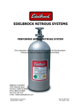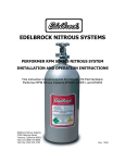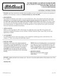
1
EDELBROCK NITROUS SYSTEMS
PERFORMER SPORT COMPACT EFI NITROUS SYSTEM
For Part Numbers 71000, 71004, & 71005
INSTALLATION AND OPERATION INSTRUCTIONS
Edelbrock Corporation
2700 California Street
Torrance, California 90503
Tech Line (800) 416-8628
Tech Fax (310) 972-2730
E-Mail: [email protected]
Rev. 5/01
Thank You….
…for purchasing an Edelbrock Nitrous Oxide Injection System.
Nitrous Oxide injection is one of the most exciting performance enhancements, for the dollar invested,
on the market today. With the use of nitrous oxide come some important safety considerations. This
manual has been written to help you during the installation and use of your Edelbrock Nitrous System.
Please read it completely before you install and use your system. Please pay close attention to the
safety information at the beginning of each section. The information contained there specifically pertains
to each of the components and installation methodologies within the section.
Please take the time to read and understand the following….
By installing your Edelbrock Nitrous System, you indicate you have read this document and you agree
with the terms stated below:
It is the responsibility of the purchaser to follow all installation instruction guidelines and safety
procedures supplied with the Edelbrock Nitrous Systems. It is also the responsibility of the purchaser to
determine the compatibility of the product with the vehicle or the device on which the purchaser intends
to install it.
Edelbrock Corporation assumes no responsibility for damages occurring from misuse, abuse, improper
installation, improper operation, lack of responsible care, or all previously-stated reasons resulting from
incompatibility with other manufacturer’s products and/or systems.
Edelbrock Corporation neither recommends nor condones the use of products manufactured or sold by
Edelbrock Corporation for use on vehicles, which may be driven on public roads or highways, and
assumes no responsibility for damages incurred by such use.
Edelbrock Corporation assumes no responsibility for damages incurred by the use of products
manufactured or sold by Edelbrock Corporation on vehicles used for competition or racing.
Edelbrock General Warranty
It is the constant endeavor of Edelbrock Corporation to give our customers the highest quality products
obtainable. Edelbrock warrants each new product, except Performer Series Carburetors, Race Division
Parts, Tubular Exhaust Systems, RPM Series Mufflers, Cat-Back Systems and Performer IAS Shock
Absorbers which are warranted separately, to be free from defects in both workmanship and material for
a period of one (1) year from the date of purchase, provided that the product is properly installed,
subjected to normal use and service and that the product is not modified or changed in any way,
negligence by customer or installer or used for racing or competition purposes.
Our warranty service and repair facility is located at 2700 California Street, Torrance, California 90503.
Customers who believe they have a defective product should either return it to the dealer from which it
was purchased or ship it directly to Edelbrock along with proof of purchase and a complete description
of the problem. The product must be returned freight pre-paid. If a thorough inspection of the product
by the factory indicates defects in workmanship or material, our sole obligation shall be to repair or
replace the product. Warranty covers only the product itself and not the cost of installation or removal.
Edelbrock Corporation shall not be liable for any and all consequential damages occasioned by
the breach of any written or implied warranty pertaining to this sale in excess of the purchase
price of the product sold.
If you have any questions regarding a product or installation, please contact our Technical
Department, toll free at 1-800-416-8628 from 7:00am to 5:00pm PST, Monday through Friday.
Thank you again for choosing Edelbrock Nitrous Systems.
EDELBROCK NITROUS SYSTEMS
PERFORMER SPORT COMPACT EFI SERIES NITROUS SYSTEM
Table of Contents
Page #
1.0
2.0
3.0
4.0
5.0
a.
Before You Install Your Edelbrock Nitrous System ...................................... 2
b.
What is Nitrous Oxide? .............................................................................. 3
c.
Safety Tips for Working with Nitrous Oxide ................................................. 3
Introduction to the Edelbrock Nitrous Systems Kit
1.1
General Information .................................................................................. 4
1.2
Jet Map Information .................................................................................. 5
1.3
Engine Operation Considerations .............................................................. 5
1.4
Performer Sport Compact EFI Series Nitrous System Bill of Materials ......... 6
Performer EFI Series Nitrous System Installation
2.1
Nitrous Bottle Mounting ............................................................................. 7
2.2
Nitrous Bottle Mounting Instructions ........................................................... 8
2.3
Nitrous Bottle Orientation .......................................................................... 8
2.4
Nitrous Bottle Installation ........................................................................... 9
2.5
Nitrous Feed Line Mounting..................................................................... 10
2.6
Solenoid Mounting .................................................................................. 10
2.7
Nitrous Spray Nozzle Installation ............................................................. 11
2.8
EFI Vacuum “Tee” Installation .................................................................. 12
2.9
Fuel Pressure Safety Switch Installation ................................................... 12
Electrical System Installation
3.1
Electrical Components Bill of Materials (BOM) .......................................... 13
3.2
Nomenclature Descriptions ...................................................................... 13
3.3
Electrical System Wiring Diagram ............................................................ 14
3.4
Electrical System Installation Procedures ................................................. 15
3.5
Relay and Fuse Holder Installation ........................................................... 15
3.6
Arming Switch and Installation ................................................................. 16
3.7
Microswitch Installation and Wiring...................................................... 16-17
3.8
Final Electrical Installation Recommendations ........................................... 17
Before You Run Your Edelbrock Nitrous System
4.1
Fuel System Check ................................................................................. 18
4.2
Nitrous System Check............................................................................. 18
Troubleshooting and Routine Maintenance .................................. 19-21
Page 1
Caution!!
Before You Install Your Edelbrock
Nitrous System…
Please read this Installation manual fully before installing this system.
You will need to have available the following tools:
Hand Tools
•
•
•
•
•
•
•
•
Socket set including ratchets and extensions
Screwdrivers
Pliers
Bench vise
Wire crimping pliers, wire strippers
Floor jack
Vehicle jack stands
Safety glasses
Power Tools
•
•
Power drill
Drill bits (1/4”, 1/2” and 3/8”)
You should understand the following skills:
•
•
•
•
•
'
Power tool safety procedures
Undercar safety procedures
Proper measuring techniques
Proper electrical assembly techniques
Basic engine operation and tuning
Anytime you have questions or concerns with your Edelbrock Nitrous System,
please call our technical support hotline at
1-800-416-8628 before you start your engine.
Page 2
WHAT IS NITROUS OXIDE?
Nitrous Oxide is a cryogenic gas composed of nitrogen and oxygen molecules. It is stored as a “gas
over a liquid” which means that both liquid and gaseous nitrous oxide is delivered into your engine. It is
36% oxygen by weight, which is what produces the added horsepower. By injecting more oxygen (and
a corresponding fuel signal), we create the additional power the same way a supercharger or a
turbocharger does.
Nitrous Oxide is considered an “oxidizer” and not a fuel. Therefore, nitrous oxide is non-flammable by
itself. Because nitrous oxide is a cryogenic, the same safety methods in handling dry ice apply to
nitrous. Direct contact with the skin will cause a burn similar to contact with dry ice. The exception in
using nitrous oxide comes from increased breathing hazards associated with the gaseous properties of
nitrous oxide.
Nitrous Oxide is offered for sale in two common grades, which are U.S.P., and Nytrous Plus. U.S.P.
nitrous oxide is medical grade nitrous oxide. Its common use is dental and veterinary anesthesia as well
as use as a propellant in food such as canned whip cream. U.S.P. is not available to the public and
would provide no advantage in the making of horsepower over the automotive grade nitrous oxide.
Nytrous Plus was specifically designed for automotive consumption and differs from U.S.P. in that it
contains trace amounts of sulfur dioxide (100 parts per million or “PPM”) added to prevent substance
abuse. The Sulfur Dioxide is an irritant to all of your breathing passageways and will create sore throats
and sore nasal passages. Nytrous Plus was specifically created for automotive applications and is
available for sale to the public at many speed shops across the USA.
þ Safety Steps For Working With Nitrous Oxide
1.
2.
3.
4.
5.
6.
7.
8.
9.
'
Never inhale Nytrous Plus (Nitrous oxide (N2O) for vehicular use) as continued exposure can
cause death. Nytrous Plus has a maximum of 100 parts per million (ppm) of sulfur dioxide and
will cause irritation to nose and throat passageways.
When working around any high-pressure gas including nitrous oxide, take all precautions to
ensure that exposure to nitrous oxide is minimized.
Do not vent nitrous oxide to atmosphere in confined spaces. Only vent nitrous oxide in
well-ventilated and open areas.
Liquid nitrous oxide can cause burns to human flesh so protect all skin in and around your
hands, arms and face. Wear safety glasses and rubber gloves to protect from liquid nitrous
oxide splatter.
When venting down the nitrous system, vent the line down closest to the nitrous bottle.
Do not use any form of Teflon tape as sealant on fitting connections. Use only Teflon paste.
When washing components, ensure the clean components are completely dry, free of oils, and
solvents. Failure to remove all liquids could cause component or system failure.
Always turn the bottle off before making any repairs to the nitrous delivery system.
To safely release nitrous oxide in a pressurized line;
a. Position vehicle in a well-ventilated, unconfined space.
b. Turn bottle off.
c. Slowly turn the nitrous feed line at the bottle open until you hear a light hissing noise.
d. Allow the entire nitrous pressure to vent from the line.
e. Perform your work on the system.
f. Re-attach the nitrous line to the bottle.
g. Slowly open the nitrous bottle valve, listening for leaks.
h. Perform leak checks on all affected fittings and the bottle fitting.
Anytime you have questions or concerns with your Edelbrock Nitrous
System, please call our technical support hotline at 1-800-416-8628 before you
start your engine.
Page 3
1.0
Introduction to your Edelbrock Performer Sport Compact EFI Nitrous System
….about this manual!
Within the pages of this manual is information, safety tips and operation instructions for your new
Edelbrock Nitrous System. Watch for these symbols to know where to go for information.
R ….There is safety related information here.
&….shows where technical information about your vehicle or specific skills that may
help during installation.
' ….call Edelbrock Technical support hotline for more information.
1.1
General Information
The Edelbrock Performer Sport Compact EFI Nitrous Systems (Part Numbers 71000,
71004, & 71005) are designed for any import vehicle with stock or slightly modified engines
utilizing a return style fuel system. Horsepower and torque increases can vary with
equipment upgrades and modifications.
This system utilizes a single nozzle that is installed in the intake pipe between the air filter
and the throttle body. The additional fuel needed with nitrous is supplied by the vehicle’s
standard fuel system.
This system has been designed with some flexibility as to where certain components can be
located to allow easy installation on vehicles with upgraded or modified equipment. The
solenoid and microswitch brackets are designed to be manipulated (bent, cut, twisted, etc.)
and the electrical components have properly-sized and ample lengths of wire.
This system includes the bottle (shipped empty), bottle feed line and universal footprint steel
bottle brackets. The mounting brackets also include rubber insulators to protect the surface
of your nitrous bottle while mounted in the brackets. When installing your nitrous bottle, pay
close attention to the installation instructions for the location of your bottle. Ensure the
installation of your bottle does not compromise any systems that may lie under the potential
location where you plan to drill holes for mounting the brackets.
Call your local automotive store, motorcycle shop or race track for refilling of your bottle.
Trust a professional to properly fill your bottle and reference your installation manual when
re-installing your filled bottle back into your vehicle.
Always take care when handling a full bottle of nitrous oxide. Please reference this manual
for further safety measures to take during the handling of a nitrous oxide bottle.
Please follow all safety methods during the installation of your Edelbrock Nitrous System,
and follow all vehicle regulations and road laws when using your nitrous system.
Page 4
1.2
Jet Map Information
Edelbrock engineering has conducted dyno testing with the Edelbrock Performer Sport
Compact EFI Nitrous System to ensure the horsepower increase of the nitrous system
is as intended. On a typically stock 1.6L engine, you can expect the following
approximate power gain:
Nitrous/Fuel Jetting
32
34
36
Approx. HP Gains
Final Air/Fuel Ratio
50
60
70
11.5/1
12.0/1
12.8/1
42
42
42
The dyno tests were conducted at Edelbrock using a stock 1.6L engine. These tests
were conducted with 950 psi nitrous bottle pressure.
1.3
Engine Operation Considerations
When used correctly, nitrous oxide safely elevates cylinder pressures and temperatures
while increasing combustion rate. These characteristics make the engine more
sensitive to detonation. To ensure proper performance, engine and drive line life, the
following tips are suggested:
•
System Jetting
Never exceed the recommended jetting!! Excessive jetting could result in severe engine
damage.
•
Fuel Quality
Because Nitrous oxide is an oxidizer, fuel selection is critical. Both octane and fuel
consistency affect fuel burn rate. The oxidizer quality of nitrous oxide will accelerate the
burn rate, so we recommend a high quality of gasoline. We also recommend you use
the same grade of gasoline every time you use your nitrous oxide system. This will help
maintain the same fuel burn rate every time.
•
Ignition Components
Most aftermarket performance chips increase the vehicle’s ignition timing, which can
cause detonation with the use of nitrous oxide. Please consult with your chip
manufacturer on information regarding the compatibility of your chip with nitrous oxide
use.
If your vehicle is equipped with platinum-type spark plugs, we highly recommend they
be removed and replaced with the equivalent standard-type spark plugs.
•
Engine System Upgrades
With all performance modifications, complementary system upgrades will always serve
to elevate the consistency and longevity of an engine, especially when using nitrous
oxide as a power adder. Modifications such as ignition upgrades, free-flowing exhaust,
camshafts, cylinder heads, manifolds, fuel controls and fuel pumps can all add to the
performance of a nitrous oxide injected engine.
Page 5
1.4
Item #
Performer Kit Bill of Materials
Qty.
Description
Nozzle and nozzle hardware
1
2
3
1
1
1
4
5
6
7
8
9
10
11
2
1
1
4
1
1
1
1
12
13
14
15
16
17
1
1
1
1
1
5
18
19
20
1
1
1
21
22
23
24
25
26
27
1
1
2
1
2
2
1
28
29
1
1
30
1
Nitrous Fan spray nozzle
Nitrous Fan spray nozzle bulkhead body bolt
Nitrous Fan spray nozzle bulkhead concave nut
Solenoids and solenoid hardware
Performer Nitrous solenoid
Solenoid tee 1/8 NPT male x 1/8 NPT female x 1/8 NPT male
EFI solenoid mounting bracket
Solenoid mounting screws (8 x 32 UNC x 5/16”)
Nitrous filter, 4AN x 1/8 NPT, straight fitting, blue
3AN x 1/8 NPT straight fitting, blue
90º swivel adapter, 4AN male x 4AN female
2 ft. 3AN steel braided hose
Nitrous Pressure Regulator and Hardware
Nitrous pressure regulator assembly
1/8 NPT male x 1/8 NPT male union, brass
EFI vacuum tee assembly
1/8 NPT x 3/16” barb, hose adapter fitting
2 ft. x 3/16” rubber fuel hose
Ratchet hose clamps, 3/16”
Fuel Pressure Safety Switch and Hardware
Fuel pressure safety switch
1/16 NPT tap
1/16 male x 1/8 female brass adapter
Bottle and Bottle Hardware
10-lb. Nitrous bottle
Nitrous bottle bracket set (1 tall, 1 short)
Rubber insulators (for brackets)
4AN x 660 Bottle nut and washer
Bolts, bottle bracket 5/16” x 18 x 1-1/2”
Nuts, bottle bracket 5/16” x 18
4AN x 14 ft. main feed line
Jets
Jet #32
Jet #42
Electrical System Components
Electrical Component Package (see page 13 for BOM)
Page 6
2.0
Performer System Installations
2.1
Nitrous Bottle Mounting
The nitrous oxide storage cylinder is typically called a “nitrous bottle”. It is an aluminum
cylinder, designed and manufactured to withstand very high pressures. The valve on
top of the bottle is a high-flow design that allows easy opening and closing which
controls the nitrous flow to the engine compartment.
Accurate calibration of your nitrous system depends on the bottle remaining at a stable
temperature. In vehicles (such as Corvettes) where the bottle must be mounted in an
area subject to direct sunlight, it is suggested that the bottle be shielded with a bottle
blanket.
If the bottle is mounted inside the passenger compartment or in a space that has
access to the passenger compartment such as hatchbacks or vehicles that feature fold
down rear seats, the pressure relief device (PRD valve) must be vented externally from
the cockpit. This procedure will prevent the passenger compartment from filling with a
cloud of nitrous oxide, should the safety pressure relief valve rupture.
Special consideration should be made to protect the bottle installation by not
placing the bottle in a known crumple or crash zone within the vehicle. At no time
should the bottle be mounted within the seating area of the passenger
compartment of a street-driven vehicle.
Performer Bottle Valve
Pressure Relief
Device
(PRD)
660 High Flow
Nitrous Exit
Here is the Performer Bottle Valve. A Pressure
Relief Device or “PRD” is installed on all bottle
valves used in Edelbrock Nitrous Systems. It is
a safety valve designed to vent the contents of
the bottle to the atmosphere in case if the
bottle pressure exceeds the safe limit.
Over-pressurization can result from over-filling,
exposure to direct sunlight or high
temperatures, or a violent strike to the bottle
surface.
It is illegal to tamper with or remove this
device.
þ Bottle Safety Information
1.
2.
3.
4.
5.
6.
Do not attempt to remove the bottle valve. Please return your bottle to Edelbrock if
service is required to the siphon tube inside the bottle or the bottle valve itself.
Never heat the outside of your nitrous bottle with an open flame like that of a torch.
Do not strike the surface of your nitrous bottle with a heavy or sharp object.
Do not drop your nitrous bottle.
Do not attempt to grind off or destroy any imprinted markings on the face of the bottle.
Do not remove, modify or otherwise tamper with the safety valve on the bottle valve.
Racing Vehicles
Before you use the Edelbrock bottle mounting brackets to mount a nitrous bottle in a vehicle
intended for use in racing or sanctioned events, check with the sanctioning association or
local racetrack for any rules regarding bottle installation. Most associations require the bottle
be mounted within the confines of the safety roll cage, with the safety pressure relief cap
vented away from the driver’s compartment.
Page 7
2.2
Bottle Mounting Instructions
Accurate calibration of your nitrous system depends on the bottle remaining at a stable
temperature. Choosing the proper location and orientation for your bottle can greatly
affect the overall operation of the nitrous system. Please read the entire bottle mounting
instruction section before making your final bottle location decisions.
2.3
Bottle Orientation
Bottle placement is critical to the performance of your nitrous system. It is important to
understand how the bottle valve and siphon tube are assembled to properly orient the
bottle in your vehicle and ensure that it picks up liquid nitrous while undergoing
acceleration. All nitrous bottles are assembled so that the bottom of the siphon tube is
at the bottom of the bottle, opposite the bottle label.
An Edelbrock nitrous bottle cannot be mounted upside-down. Edelbrock does not
offer a non-siphon tube bottle for automotive use. If the bottle must be mounted
parallel to the axles of the vehicle (sideways), the valve handle and label must be
angled at approximately 45 degrees toward the front of the vehicle. This
orientation will position the siphon tube toward the rear and pointing to the lower
rear-facing quadrant of the bottle. All of this positioning information is critical to
system operation. It is most important to draw as much liquid nitrous as possible.
The siphon tube cannot do this unless the bottle is positioned correctly.
The most efficient mounting is the lay-down position with the valve handle
toward the front of the vehicle. This position allows the greatest amount of
liquid to be used before the siphon tube begins to pick up gaseous nitrous
oxide.
Page 8
2.4
Nitrous Bottle Installation
After you have determined the location and orientation of the nitrous bottle, use the
following procedure to install the bottle:
2.4.1 Street Car Installations
1.
2.
3.
Disconnect vehicle’s battery.
Determine the location of the bottle within the confines of the rear of the vehicle.
Once a mounting location has been determined, raise the vehicle (following all
safety practices involved in working on a vehicle from under the vehicle) and verify
that there are no fuel lines, fuel tank(s), brake lines, emissions equipment, or
structural members in the way of potential mounting bolt locations.
Note: It may be necessary to remove the fuel tank depending on the location you
wish to install the bottle.
4.
Using the mounting bracket bolt holes as templates, mark an area for each of the
two (2) brackets with chalk, metal marking pen, scribe, or marking pen to locate the
bolt placements for drilling.
5. Drill two (2) 3/8” mounting holes for each bracket.
6. Install the bottle mounting brackets using “Grade 8” bolts, nuts and flat washers (not
included with kit).
7. Tighten the mounting bolts using a thread locking chemical (not included with kit).
8. Install the rubber insulators within the bottle brackets.
9. Slip bottle into the mounting brackets.
10. Tighten bracket clamps as shown in the picture.
Shown here is a bottle with a
bottle bracket properly installed
with the rubber insulator. The
distance between the bottle
brackets is somewhat adjustable.
Remember, mount the short bottle
bracket at least 1” from the
bottom of the bracket, and never
cover any of the bottle label with a
bottle bracket.
Do not attempt to install the bottle
in the bracket without the rubber
insulator. The bottle hoop on the
bracket is dimensioned to include
the thickness of the insulator.
2.4.2 Race Car Nitrous Bottle Installations
Install the bottle brackets in accordance to race track and/or sanctioning body
rules. Contact the factory for assistance with meeting sanctioning body rules.
2.4.3 Nitrous Bottle Installations For Vehicles With Hatchbacks Or
Trunk Areas That Are Connected With The Passenger
Compartment.
Please contact Edelbrock for more information.
Page 9
2.5
Nitrous Feed Line Mounting
1.
2.
3.
4.
5.
2.6
Determine the route your main nitrous feed line will follow. Ensure the path does
not route the nitrous feed line too close to the exhaust system, suspension,
electrical lines/components and tires.
Attach nitrous supply line to bottle.
Feed nitrous line along proposed route.
Secure nitrous supply line to underside of vehicle.
þ Note: Stainless steel covering of the main nitrous feed line is very abrasive.
Shield painted components or sensitive system components like
electrical, fuel lines, brake lines or suspension components to prevent
them from contacting main feed line. Rubber hose can be slid over and
retained as a chafe guard.
Leave nitrous line loose pending installation of nitrous solenoid.
Solenoid Mounting
Use the following procedures to install the Performer nitrous solenoids:
Note: Remember to use Teflon paste only on pipe threads. Do not use Teflon tape.
Hint: Placement of the solenoid is often limited by the lack of possible mounting
locations in the engine compartment. However, if possible, observe the following
suggestions:
þ Solenoid Safety Information
1.
2.
3.
Keep solenoid and lines away from exhaust components.
Trial fit the solenoids with all lines attached to ensure a proper fit.
Solenoids may be mounted sideways or upside-down, if necessary.
2.6.1 Preparing To Mount Your Solenoids
1.
2.
Locate the EFI solenoid bracket, solenoid “tee”, and solenoid mounting screws.
This solenoid bracket can be modified (bent, twisted and/or cut) to allow for
easier installation in areas with minimal clearance . Please look at the photo on
the next page of a typical solenoid mounting location, and adapt your bracket
according to the needs of your particular application.
2.6.2 Nitrous Solenoids and Nitrous Pressure Regulator Mounting
1.
2.
3.
4.
5.
Hold one of the nitrous solenoids securely (like in a bench vise) being careful
not to harm the solenoid or block the inlet or outlet of the solenoid.
Install nitrous filter fitting (Blue fitting 4AN X 1/8 NPT) using liquid Teflon, in the
inlet port of the nitrous solenoid.
Install one of the 1/8 NPT male sides of solenoid “tee”, using liquid Teflon, on
the outlet port of the nitrous solenoid. The female port of solenoid “tee” should
be facing outward.
Install the remaining 1/8 NPT male end of the solenoid “tee”, using liquid Teflon,
into the inlet port of the second nitrous solenoid. Rotate second solenoid so
that it parallels the first.
Install the 3AN x 1/8 NPT (blue straight fitting) into the outlet port of second
nitrous solenoid.
Page 10
6.
Install one end of the 1/8 NPT male x 1/8 NPT male nipple fitting, using liquid
Teflon, into nitrous pressure regulator inlet port.
7. Loosely thread nitrous pressure regulator/nipple assembly into 1/8 NPT female
port on solenoid “tee”.
8. Using liquid Teflon, install 1/8 NPT x 3/16” barb fitting into nitrous pressure
regulator.
i. Remove nitrous solenoid/regulator assembly from vise.
ii. Attach EFI solenoid bracket to the bottom of the solenoids.
ii. Verify the desired mounting location for the solenoid/regulator assembly.
9. Install solenoid/regulator assembly in desired location.
10. Tighten nitrous regulator until barb fitting points towards the vehicle’s fuel
pressure regulator.
11. Leave all wiring loose for electrical systems installation.
12. Connect main nitrous feed line to inlet fitting (4AN x 1/8 NPT nitrous filter fitting)
of the first nitrous solenoid.
Here is a typical EFI solenoid/regulator
assembly (regulator not installed), mounted
in the engine compartment of a vehicle, using
a non-modified EFI solenoid bracket.
Modifications performed to a solenoid
bracket depend on many factors. When
mounting the solenoid/regulator assembly on
the vehicle, considerations should be taken
regarding any potential interference with the
vehicle’s systems or components.
The line length between the Performer EFI
solenoid/regulator assembly and the jet fitting
on the nitrous spray nozzle is 24 inches.
This should also be considered when
mounting the solenoid/regulator assembly.
2.7
Nitrous Spray Nozzle Installation
1.
2.
3.
4.
5.
6.
7.
8.
9.
Determine
nozzle
mounting
location in air inlet pipe, between
air filter and throttle body, making
sure the nozzle, mounting collar,
and the feed line from solenoid to
nozzle, do not interfere with any
systems or components of the
vehicle.
Remove air inlet pipe.
Drill a 7/16” hole in inlet pipe
where nozzle placement has been
determined.
Install nozzle mounting nut and
collar onto inlet pipe.
Install inlet pipe.
Mark the spray direction on the
nozzle.
Using liquid Teflon, install the spray nozzle into the air inlet pipe making sure the
nozzle discharge is toward the vehicle’s engine.
Install recommended jet into nozzle fitting.
Install 3AN line from solenoid outlet fitting to spray nozzle jet fitting and tighten
securely.
Page 11
2.8
EFI Vacuum “Tee” Installation
1.
2.
3.
4.
5.
2.9
Install the recommended jet
(page 5) into the EFI Vacuum
“Tee” and tighten fitting securely.
Remove vacuum line from the
vehicle’s fuel pressure regulator.
Install vacuum line from the
vehicle’s fuel pressure regulator
onto the center barb fitting of the
EFI Vacuum “Tee”.
Note: The center barb can easily
be identified by the anodized nut
used to hold the Pressure Relief
Jet.
Measure the correct length of
vacuum line from the barb on the
Fuel Pressure Regulator to one port of the EFI Vacuum “Tee”. Cut vacuum line and
install.
Measure the correct length of vacuum line from the barb fitting of the nitrous
pressure regulator to the remaining open port on the EFI Vacuum “Tee”. Cut
vacuum line and install.
Fuel Pressure Safety Switch Installation
1.
2.
3.
4.
Locate fuel rail test port fitting.
Make sure the vehicle’s engine
is cool, release pressure in fuel
system by pressing down on
valve in center of the fitting. This
will allow the pressure to
escape as well as some fuel.
After relieving all pressure,
remove test port fitting core and
install the 1/16 NPT male x 1/8
NPT female brass fitting in its
place, using liquid Teflon.
Using liquid Teflon, install Fuel
Pressure Safety Switch into
1/16 NPT male x 1/8 NPT
female brass adapter.
Note: On some vehicles, there is no test port fitting, or the location of the test port fitting
does not allow ample room for the fuel pressure safety switch to be mounted. These
applications (as shown in the photo) will require the “Banjo nut” at the fuel filter to be
drilled and tapped (1/16 NPT tap supplied with system) to allow mounting of the fuel
pressure safety switch.
Page 12
3.0
Electrical System Installation
3.1
3.2
Electrical Components Bill of Materials (BOM)
Item
Quantity
Description
1
1 ea.
Activation microswitch
2
1 ea.
Activation microswitch bracket (not shown)
3
2 ea.
Activation microswitch mounting nut
4
2 ea.
Activation microswitch mounting screw
5
1 ea.
30 amp relay
6
1 ea.
Wire harness with integral relay/fuse holder
7
1 ea.
Red lighted toggle switch
8
2 ea.
18/22g female spade connector, Nylon insulated
9
2 ea.
14/16g female spade connector, Nylon insulated
10
1 ea.
14/16g male spade connector, Nylon insulated
11
1 ea.
16/18, splice connector
12
1 ea.
14/16g 3/8” ring terminal, Nylon insulated
13
3 ea.
18/22g ring terminal #10 Stud, Nylon insulated
14
2 ea.
18/22g ring terminal #8 Stud, Nylon insulated (.187)
15
2 ea.
18/22g female spade connector, Nylon insulated
16
1 ea.
15 amp ATO blade fuse
Nomenclature Descriptions:
ATO… the fuse configuration is ATO. When replacing this fuse, ask for an ATO
fuse.
“a”… Amperage.
Important: The wiring hardware and instructions included with this kit are intended for 12-volt
electrical systems only. Before attempting to wire your Edelbrock Performer nitrous oxide system,
examine and follow the wiring diagram on the following page. Please call the Edelbrock technical
department with any questions concerning electrical wiring.
working with electrical systems in your vehicle, it is a good idea to have a service manual
that features your vehicle. It is also good practice to have a book that specializes in the
& When
techniques required when working with vehicular electrical systems.
Page 13
3.3 Electrical System Wiring Diagram
Page 14
3.4
Electrical System Installation Procedures
Determine the location of the Relay and Fuse Holder wire harness. Most common
installations locate these components inside the driver’s compartment and close to the fuse
panel under the dash. You can also mount the Relay and Fuse Holder and harness close to
the battery. However, these connectors are water-resistant not waterproof, so care is
required when mounting this assembly under the hood of your vehicle.
Wire Schematic Origin and Destination Map
3.5
Wire Color
System
Origin
Destination
Terminal Used
Red
Main System Bat.
Voltage
Relay Harness
Bat. Volt. Signal
Ring
Red
Arming Switch
Arming Switch
Underdash Switched
12V
Spade/Wire
Intercept
Blue
Solenoid Power
Relay Harness
Solenoids #1 & #2
Spade
White
Relay Power
Relay Harness
Arming Switch
Spade
Black
Arming Switch
Grnd
Arming Switch
Chassis Grnd
Spade/Ring
Black
Relay Grnd
Relay Harness
Microswitch
Spade
Black
Microswitch Grnd
Microswitch
Chassis Grnd
Spade/Ring
Black
Solenoid #1 Grnd
Solenoid #1
Chassis Grnd
Ring
Black
Solenoid #2 Grnd
Solenoid #2
Fuel Pressure Safety
Switch
Ring
Black
Fuel Pressure
Safety Switch Grnd
Fuel Pressure
Safety Switch
Chassis Grnd
Ring/Ring
Relay and Fuse Holder Installation
The wire harness attached to the relay and fuse holder includes 8 feet of color-coded wires
to make the electrical system installation for your Edelbrock Nitrous System as easy as
possible. We recommend that you do not cut any lengths of wires from the wire harness or
complete the wiring of the nitrous system until all of the mechanical components are
securely mounted in their permanent locations.
Once all of the solenoids and switches are placed, then route the un-cut wires from the
harness to each location allowing enough wire length on each circuit to not interfere with
operating linkages, heat sources, brackets, etc. Pay particular attention to sharp edges
along the route of your wire harness as they can chafe the wire and cause your system to
fail.
After you have accounted for the routing of your wires, follow the Wire Harness Schematic
on page 14 and use the Origin and Destination Map as a guide for which electrical
connectors are used in each circuit.
Once you have decided the location of the relay and fuse holder, secure them with
fasteners (not included with kit) such as sheet metal screws, bolts and nuts, etc. Allow for
some slack in the red wire that connects the relay and fuse holders together.
When mounting your relay and fuse holder, make sure the mounting surface is strong
enough to support servicing the relay and fuse easy. Also, ensure you allow for some slack
in the wire that joins the fuse holder to the relay mount. This will avoid any potential loss of
power due to stress on the wire harness.
The fuse is covered by the fuse mount housing.
The relay for the Performer system is 30 amps, and the fuse is 15 amps.
Page 15
3.6
Arming Switch and Installation
The arming switch is a red, lighted switch that is a “MASTER” arming switch for your
nitrous system. Without it, your nitrous system would be “on” all of the time and capable
of engaging anytime you go to wide-open throttle conditions with your vehicle. The
switch, when in the “armed” position, is well lit. Therefore, it should be placed in an
obvious position well within the line of sight and easy reach of the driver. Please refer to
the procedures below for the installation of the arming switch:
1.
2.
3.
4.
Locate the final position of your arming switch.
Drill a 1/2” hole for the switch location.
Insert the switch from behind the mounting hole and secure with the switch nut.
Do not wire until all other mechanical components are in place. Please see the
electrical system installation instructions for further information.
Note: There is a collar included with the switch for applications that require special
spacing during installation.
3.7
Microswitch Installation and Wiring
The function of your microswitch is to enable your nitrous system. It should be installed
so that the switch is forced closed by coming in contact with the throttle linkage only at
the wide open throttle position. The nitrous system must only function at fully-loaded
wide-open throttle.
þ MICROSWITCH SAFETY INFORMATION
1.
2.
3.
4.
Do not allow wiring from the microswitch to come in contact with heat sources on
the intake manifold such as EGR risers or passageways.
Do not run wires to the microswitch that can create interference with the operation
of the throttle linkage.
The microswitch must be located in such a way as to be clear of the normal
operation of the throttle linkage.
Do not directly expose the microswitch to liquids such as water or gasoline.
This is a picture of an unmodified and a “ready to install” microswitch assembly. The
microswitch bracket has several mounting positions available for clocking of the switch. It
also is of a universal length and can be attached to several positions on and around the
throttle body.
Page 16
3.7
Microswitch Installation and Wiring (Continued)
The bolts used to attach the microswitch have extra length to allow for spacing the
microswitch away from the bracket if necessary. After determining the position of the
microswitch, we recommend trimming the bolts for a clean installation.
Due to the wide variety of throttle linkage combinations in use, it is impossible to supply
a microswitch bracket custom-tailored to each application. The universal bracketsupplied will need to be modified to fit your specific application.
Here is the microswitch
assembly mounted for use with
an Edelbrock Throttle body
(#3843). It is an example of one
of many ways in which to mount
a microswitch on your manifold.
The microswitch bracket allows
for many different mounting
positions. The microswitch
bracket can be modified to clear
almost any potential interference
around the throttle linkage.
Please look for potential microswitch mounting locations and adapt your microswitch
bracket according to the needs of your particular application.
The microswitch bracket is drilled to allow many different switch mounting positions.
This flexibility allows the microswitch to be positioned in such a manner that it will
engage the throttle linkage without interfering with its normal and safe operation. The
bracket may be manipulated (bent, twisted, and/or cut) to best suit your combination.
Mount the microswitch so the actuation arm is triggered by throttle linkage making sure
all wiring and the bracket do not interfere with the smooth and safe operation of the
throttle linkage.
Adjust microswitch to ensure the actuation arm “clicks” at the same point your throttle
linkage reaches wide open throttle against the throttle stop. At no time should the
microswitch be enabled before wide open throttle.
3.8
Final Electrical installation Recommendations
þ
1.
2.
3.
At this time, it is advised that you double-check the following areas:
Double-check all wires so that they do not come in contact with any heat sources
such as exhaust manifolds, or EGR crossovers.
Double-check the wires that lead from the microswitch to ensure they do not
interfere with the operation of the throttle linkage.
Make sure the relay and the fuse are serviceable and mounted securely.
You are ready to hook up your battery and prepare your vehicle to run.
Page 17
4.0
Before You Run Your Vehicle Using Your Edelbrock Nitrous System
You have just completed the installation of your Edelbrock Nitrous System. It is time to perform
some basic system checks to ensure all of the work you have done is correct and ready to
operate properly. The following procedure is designed to validate the operation of your nitrous
system before operating your vehicle:
R Note:
4.1
Fuel System Check
1.
2.
3.
4.
4.2
Before performing steps 1 thru 4, make sure that the nitrous bottle is closed
and main nitrous supply line is empty of any nitrous.
Hook up all battery leads.
Double-check all wires and leads for signs of heat and proper connections.
Start your vehicle.
Inspect fuel rail where Fuel Pressure Safety Switch has been installed for any leaks.
Nitrous System Check
1. With the vehicle’s engine running, slowly open nitrous bottle valve.
Note: There should be no change in engine idle speed. If idle speed changes,
close nitrous bottle valve immediately and refer to the “Troubleshooting
Guide” on pages 19-21.
2. Inspect nitrous lines and fittings for leaks using a soapy water mixture and a small
brush.
3. If any of the fittings/connections show bubbling around the attachment nut or on the
threaded area of the fitting, shut the nitrous bottle valve off immediately and dry the
fitting before attempting any service to that particular fitting connection.
4. If the engine idle does not come up, and all of the fittings appear to be leak-free,
you have successfully completed the installation of you Edelbrock Nitrous System.
Page 18
5.0
Troubleshooting and Routine Maintenance
How to use our Troubleshooting Flowchart:
The troubleshooting of a nitrous system is basic and straightforward. The symptom chart is divided by
symptom, cause and action required. Determine your problem (symptom), identify the potential problem
(cause) and correct the problem (action required).
Symptom #1… Change in engine speed when nitrous bottle valve is opened.
1.
2.
Malfunctioning nitrous solenoid.
a. Refer to solenoid inspection and repair on page 21.
b. Repair/replace solenoid.
Contamination in nitrous solenoid.
a. Refer to solenoid inspection and repair on page 21.
b. Clean/replace solenoid.
Symptom #2… Engine runs excessively rich when system is activated.
1.
2.
3.
4.
Nitrous bottle valve not fully opened.
a. Check bottle valve.
b. Open valve fully.
Nitrous bottle mounted improperly.
a. Mount bottle properly. See manual pages 7-8 for more information.
Plugged nitrous filter.
a. Clean and/or replace nitrous filter.
b. See nitrous solenoid symptom #1.
Low bottle pressure.
a. Weigh bottle.
1. Bottle should be 10 lbs. above empty, bottle weight listed on bottle label.
b. Check bottle temperature.
1. Maintain 80 to 85 degrees of bottle surface temperature.
Symptom #3… No change in performance when system is activated.
1.
System wired incorrectly.
a. Compare wiring to schematic. See page 14.
b. Wire per instructions.
2.
Loose ground wires.
a. Connect test light to battery “+” (positive) terminal. Check for continuity at grounds.
b. Tighten/repair loose grounds.
3.
No power to arming switch.
a. With ignition “on”, connect test light to battery “–” (negative) terminal. Check for power
at pole #1 on arming switch.
b. Repair wiring as necessary.
4.
Malfunctioning arming switch.
a. With ignition “on”, turn arming switch “on.” Connect test light to battery “–” (negative)
terminal. Check for power at terminal #1 wire on arming switch.
b. If power is present, replace arming switch.
5.
Malfunctioning microswitch.
a. Turn arming toggle “off”. Close throttle microswitch, check for continuity between
microswitch wiring terminals.
b. If continuity is present, replace microswitch.
Page 19
6.
Inadequate nitrous supply.
a. Weigh bottle.
1. Bottle should be 10 lbs. above empty bottle weight listed on bottle label when full.
b. Check bottle pressure.
1. Maintain 900-950 psi for optimum system performance.
c. Check bottle temperature.
1. Maintain 80 to 85 degrees of bottle surface temperature.
d. Check bottle valve.
1. Open valve fully.
e. Check bottle orientation. See page 8.
1. Mount bottle properly.
7.
Mismatched nitrous/vacuum “TEE” jetting.
a. Compare jetting to recommended values. See page 5.
1. Install correct jets
b. Verify the number stamped in the jet.
1. Acquire the right size jets and install correct jets.
8.
Loose nitrous solenoid wiring.
a. Inspect solenoid wiring. See pages 13-14 for wiring information.
b. Repair wiring as necessary.
9.
Malfunctioning nitrous solenoid.
a. Inspect solenoid wiring. See pages 13-14 for wiring information.
1. Repair wiring as necessary.
b. Inspect solenoid. See symptom # 2.
1. Rebuild/replace solenoid.
Symptom #4… Engine detonates mildly when sy stem is activated.
1.
2.
3.
5.
Excessive ignition timing.
a. Check Timing.
1. Reduce timing in 2-degree increments for every 50 hp.
Inadequate octane fuel.
a. Verify what gasoline you use.
1. Use higher-octane fuel.
Spark plug heat range too high.
a. Verify what heat range the spark plug is, and how it functions in a high load, high
performance application.
1. Install a performance spark plug.
2. Reduce spark plug heat range.
Too much nitrous flow.
a. Verify the size of the nitrous jet.
1. Install the proper nitrous jet.
b. Check bottle temperature and pressure.
1. Ensure before every nitrous usage that you only use nitrous when the
temperature and pressure of your bottle are correct.
Page 20
Symptom #6… Vehicle surges under acceleration when system is activated.
1.
Inadequate nitrous supply.
a. Weigh bottle.
1. Bottle should be 10 lbs. above empty bottle weight listed on bottle label when full.
b. Check bottle temperature.
1. Maintain 80 to 85 degrees of bottle surface temperature.
c. Check bottle valve.
1. Open valve fully
d. Check bottle orientation. See pages 7-8.
1. Mount bottle properly.
Solenoid inspection and maintenance.
1.
2.
Close valve on nitrous bottle.
Make sure all nitrous and fuel supply lines are free of pressure before removal of any system
solenoid.
a. Empty main nitrous supply line at the nitrous bottle. Take care to not breathe or expose your
skin to nitrous.
b. Do not open pressurized fuel lines over a hot engine. Have a fuel safe container ready to
catch all fuel that escapes from the fuel line. Avoid breathing fuel vapors and protect your
skin from fuel exposure.
3. Remove nitrous/fuel solenoid from the engine and securely clamp it into a vise, taking great care
not to damage the solenoid.
4. Remove the solenoid cover, retaining nut from top of the nitrous/fuel solenoid.
5. Remove coil and housing from nitrous/fuel solenoid base.
6. Unscrew stem from nitrous/fuel solenoid base. Do this by using a solenoid stem removal tool or
by “double nutting” the stem and unscrewing the stem from the housing body. Do not use
pliers on solenoid stem; damage to the stem will result.
7. Remove the stem, spring and plunger from the solenoid base paying close attention to the way
they are assembled.
8. Examine the plunger seal for swelling, cuts and abrasions. The seal surface should be flat,
except for a small circular indentation in the center of the seal.
A seal that has been contaminated or over-pressurized will bulge from exposure to
chemicals other than fuel or nitrous oxide. It can appear to extend down from the plunger and
be dome-shaped. A contaminated seal may return to its original shape if left out in fresh air for
approximately 48 hours. It may then be returned to service. If it does not return to its original
shape, it must be replaced.
9. Clean the solenoid body. Do not use an oil-based solvent to clean any part of the solenoid.
Remove any contaminants that may be present. Make sure solenoid body is clean, dry and free
of oils before assembly.
10. Replace the O-Ring, plunger and piston spring.
11. Re-assemble solenoid by reversing disassembly procedure.
Page 21
Edelbrock Nitrous Systems
This page is left for notes:
Edelbrock Corporation
2700 California Street
Torrance, California 90503
Phone (800) 416-8628