1
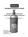
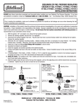
Thank You….
…for purchasing an Edelbrock Nitrous Oxide Injection System.
Nitrous Oxide injection is one of the most exciting performance enhancements, for the dollar invested, on the market today.
With the use of nitrous oxide come some important safety considerations. This manual has been written to help you during
the installation and use of your Edelbrock Nitrous System. Please read it completely before you install and use your
system. Please pay close attention to the safety information at the beginning of each section. The information contained
there specifically pertains to each of the components and installation methodologies within the section.
Please take the time to read and understand the following….
By installing your Edelbrock Nitrous System, you indicate you have read this document and you agree with the terms stated
below:
It is the responsibility of the purchaser to follow all installation instruction guidelines and safety procedures supplied with
the Edelbrock Nitrous Systems. It is also the responsibility of the purchaser to determine the compatibility of the product
with the vehicle or the device on which the purchaser intends to install it.
Edelbrock Corporation assumes no responsibility for damages occurring from misuse, abuse, improper installation,
improper operation, lack of responsible care, or all previously-stated reasons resulting from incompatibility with other
manufacturer’s products and/or systems.
Edelbrock Corporation neither recommends nor condones the use of products manufactured or sold by Edelbrock
Corporation for use on vehicles, which may be driven on public roads or highways, and assumes no responsibility for
damages incurred by such use.
Edelbrock Corporation assumes no responsibility for damages incurred by the use of products manufactured or sold by
Edelbrock Corporation on vehicles used for competition or racing.
Edelbrock General Warranty
It is the constant endeavor of Edelbrock Corporation to give our customers the highest quality products obtainable.
Edelbrock warrants each new product, except Performer Series Carburetors, Race Division Parts, Tubular Exhaust
Systems, RPM Series Mufflers, Cat-Back Systems and Performer IAS Shock Absorbers which are warranted separately,
to be free from defects in both workmanship and material for a period of one (1) year from the date of purchase, provided
that the product is properly installed, subjected to normal use and service and that the product is not modified or changed
in any way, negligence by customer or installer or used for racing or competition purposes.
Our warranty service and repair facility is located at 2700 California Street, Torrance, California 90503. Customers who
believe they have a defective product should either return it to the dealer from which it was purchased or ship it directly to
Edelbrock along with proof of purchase and a complete description of the problem. The product must be returned freight
pre-paid. If a thorough inspection of the product by the factory indicates defects in workmanship or material, our sole
obligation shall be to repair or replace the product. Warranty covers only the product itself and not the cost of installation
or removal.
Edelbrock Corporation shall not be liable for any and all consequential damages occasioned by the breach of any
written or implied warranty pertaining to this sale in excess of the purchase price of the product sold.
If you have any questions regarding a product or installation, please contact our Technical Department, toll free
at 1-800-416-8628 from 7:00am to 5:00pm PST, Monday through Friday.
Thank you again for choosing Edelbrock Nitrous Systems.
PERFORMER RPM SERIES NITROUS SYSTEM
Table of Contents
Page #
1.0
2.0
a.
Before You Install Your Edelbrock Nitrous System . . . . . . . . . . . . . . . . . . . . . . . . . . . . . . . . . 2
b.
What is Nitrous Oxide? . . . . . . . . . . . . . . . . . . . . . . . . . . . . . . . . . . . . . . . . . . . . . . . . . . . . . 3
c.
Safety Tips for Working with Nitrous Oxide. . . . . . . . . . . . . . . . . . . . . . . . . . . . . . . . . . . . . . . 3
Introduction to the Edelbrock Nitrous Systems Kit
1.1
General Information . . . . . . . . . . . . . . . . . . . . . . . . . . . . . . . . . . . . . . . . . . . . . . . . . . . . . . . . 4
1.2
Jet Map Information . . . . . . . . . . . . . . . . . . . . . . . . . . . . . . . . . . . . . . . . . . . . . . . . . . . . . . . . 5
1.3
Engine Operation Considerations . . . . . . . . . . . . . . . . . . . . . . . . . . . . . . . . . . . . . . . . . . . . . . 5
1.4
Performer RPM System Bill of Materials. . . . . . . . . . . . . . . . . . . . . . . . . . . . . . . . . . . . . . . . . 6
Performer RPM System Installation
2.1
Nitrous Bottle Mounting . . . . . . . . . . . . . . . . . . . . . . . . . . . . . . . . . . . . . . . . . . . . . . . . . . . . . 7
2.2
Bottle Orientation . . . . . . . . . . . . . . . . . . . . . . . . . . . . . . . . . . . . . . . . . . . . . . . . . . . . . . . . . . 8
2.3
Nitrous Bottle Installation . . . . . . . . . . . . . . . . . . . . . . . . . . . . . . . . . . . . . . . . . . . . . . . . . . . . 9
2.4
Nitrous Feed Line Mounting . . . . . . . . . . . . . . . . . . . . . . . . . . . . . . . . . . . . . . . . . . . . . . . . . 10
2.5
Solenoid Mounting . . . . . . . . . . . . . . . . . . . . . . . . . . . . . . . . . . . . . . . . . . . . . . . . . . . . . . . . 10
2.6
Nitrous Solenoid Mounting and Installation . . . . . . . . . . . . . . . . . . . . . . . . . . . . . . . . . . . . . . 11
2.7
Fuel Solenoid Mounting and Installation . . . . . . . . . . . . . . . . . . . . . . . . . . . . . . . . . . . . . . . . 12
2.8
Nitrous/Fuel Solenoid Disassembly and Inspection . . . . . . . . . . . . . . . . . . . . . . . . . . . . . . . . 12
2.9
Nitrous Injection Plate Installation. . . . . . . . . . . . . . . . . . . . . . . . . . . . . . . . . . . . . . . . . . . . . 13
2.10 Solenoid/Plate Plumbing Installation . . . . . . . . . . . . . . . . . . . . . . . . . . . . . . . . . . . . . . . . . . . 13
2.11 Electrical System Installation . . . . . . . . . . . . . . . . . . . . . . . . . . . . . . . . . . . . . . . . . . . . . . . . 14
2.12 Relay and Fuse Holder Installation. . . . . . . . . . . . . . . . . . . . . . . . . . . . . . . . . . . . . . . . . . . . 16
2.13 Arming Switch . . . . . . . . . . . . . . . . . . . . . . . . . . . . . . . . . . . . . . . . . . . . . . . . . . . . . . . . . . . 17
2.14 Microswitch Installation and Wiring . . . . . . . . . . . . . . . . . . . . . . . . . . . . . . . . . . . . . . . . . 17-18
2.15 Final Electrical Installation Recommendations . . . . . . . . . . . . . . . . . . . . . . . . . . . . . . . . . . . 18
3.0
Before You Run Your Vehicle With Nitrous . . . . . . . . . . . . . . . . . . . . . . . . . . . . . . . . . . . . . . . . 18
4.0
Baseline Tuning Suggestions . . . . . . . . . . . . . . . . . . . . . . . . . . . . . . . . . . . . . . . . . . . . . . . . . . . 19
5.0
Ignition Timing and Nitrous Oxide. . . . . . . . . . . . . . . . . . . . . . . . . . . . . . . . . . . . . . . . . . . . . 20-21
6.0
Trouble Shooting and Routine Maintenance. . . . . . . . . . . . . . . . . . . . . . . . . . . . . . . . . . . . . 22-25
© 2001 Edelbrock Corporation
Brochure No. 63-0040
Page 1 of 25
Rev. 11/01
Caution!!
Before You Install Your Edelbrock Nitrous System…
Please read this Installation manual fully before installing this system.
You will need to have available the following tools:
Hand Tools
•
Socket set including ratchets and extensions
•
Screwdrivers
•
Pliers
•
Bench vise
•
Wire crimping pliers, wire strippers
•
Floor jack
•
Razor blade or other sharp, flat edged cutting instrument
•
Vehicle jack stands
•
Safety glasses
•
Timing light
Power Tools
•
Power drill
•
Drill bits
You should understand the following skills:
•
Power tool safety procedures
•
Undercar safety procedures
•
Proper measuring techniques
•
Proper electrical assembly techniques
•
Basic engine operation and tuning techniques which include:
-Fuel pressure measurement techniques
-Timing adjustment techniques
'
Anytime you have questions or concerns with your Edelbrock Nitrous System, please
call our technical support hotline at
1-800-416-8628 before you start your engine.
© 2001 Edelbrock Corporation
Brochure No. 63-0040
Page 2 of 25
Rev. 11/01
WHAT IS NITROUS OXIDE?
Nitrous Oxide is a cryogenic gas composed of nitrogen and oxygen molecules. It is stored as a “gas over a liquid” which
means that both liquid and gaseous nitrous oxide is delivered into your engine. It is 36% oxygen by weight, which is what
produces the added horsepower. By injecting more oxygen (and a corresponding fuel signal), we create the additional
power much like a supercharger or a turbocharger does.
Nitrous Oxide is considered an “oxidizer” and not a fuel. Nitrous oxide is non-flammable by itself. Because nitrous oxide
is a cryogenic, the same safety methods in handling dry ice apply to nitrous. Direct contact with the skin will cause a burn
similar to contact with dry ice. The exception in using nitrous oxide comes from increased breathing hazards associated
with the gaseous properties of nitrous oxide.
Nitrous Oxide is offered for sale in two common grades, which are U.S.P., and Nytrous Plus. U.S.P. nitrous oxide is medical
grade nitrous oxide. Its common use is dental and veterinary anesthesia as well as use as a propellant in food such as
canned whip cream. U.S.P. is not available to the public and would provide no advantage in the making of horsepower over
the automotive grade nitrous oxide.
Nytrous Plus was specifically designed for automotive consumption and differs from U.S.P. in that it contains trace amounts
of sulfur dioxide (100 parts per million or “PPM”) added to prevent substance abuse. The Sulfur Dioxide is an irritant to all
of your breathing passageways and will cause sore throats and sore nasal passages. Nytrous Plus was specifically
created for automotive applications and is available for sale to the public at many speed shops across the USA.
R Safety Steps For Working With Nitrous Oxide
1.
2.
3.
4.
5.
6.
7.
8.
9.
Never inhale Nytrous Plus (Nitrous oxide (N 2O) for vehicular use) as continued exposure can cause death.
Nytrous Plus has a maximum of 100 parts per million (ppm) of sulfur dioxide and will cause irritation to nose
and throat passageways.
When working around any high-pressure gas including nitrous oxide, take all precautions to ensure that
exposure to nitrous oxide is minimized.
Do not vent nitrous oxide to atmosphere in confined spaces. Only vent nitrous oxide in well-ventilated and
open areas.
Liquid nitrous oxide can cause burns to human flesh so protect all skin in and around your hands, arms
and face. Wear safety glasses and rubber gloves to protect from liquid nitrous oxide splatter.
When venting down the nitrous system, vent the line down closest to the nitrous bottle.
Do not use any form of Teflon tape as sealant on fitting connections. Use only Teflon paste.
When washing components, ensure the clean components are completely dry, free of oils, and solvents.
Failure to remove all liquids could cause component or system failure.
Always turn the bottle off before making any repairs to the nitrous delivery system.
To safely release nitrous oxide in a pressurized line;
a.
Position vehicle in a well-ventilated, unconfined space.
b.
Turn bottle off.
c.
Slowly loosen the nitrous feed line at the bottle until you hear a light hissing noise.
d.
Allow the entire nitrous pressure to vent from the line.
e.
Perform your work on the system.
f.
Tighten the nitrous line to the bottle.
g.
Slowly open the nitrous bottle valve, listening for leaks.
h.
Perform leak checks on all effected fittings and the bottle fitting.
© 2001 Edelbrock Corporation
Brochure No. 63-0040
Page 3 of 25
Rev. 11/01
1.0
Introduction to your Edelbrock Performer RPM Nitrous System
….about this manual!
Within the pages of this manual is information, safety tips and operation instructions for your new Edelbrock Nitrous
System. Watch for these symbols to know where to go for information.
R ….There is safety related information here.
where technical information about your vehicle or specific skills that may help during
& ….shows
installation.
' ….call Edelbrock Technical support hotline for more information.
1.1
General Information
The Edelbrock Performer RPM Nitrous System (Part number 70070) is intended for use on
domestic V-8 engines using the Pro-Flo manifold, throttle body and injection. Horsepower and
torque increases can vary with engine displacement, equipment upgrades and modifications. Approximate
power increase estimates can be made based on the mass flow of nitrous oxide into the engine.
These types of systems utilize an adjustable plate that sandwiches in between the throttle body and the
throttle body mounting pad on the intake manifold. The adjustability comes from the ability of the plate to
accept different orifice-sized jets. The plate has jet fittings at opposite ends of the plate that control the
amount of nitrous oxide and fuel flow into the engine.
This system has been designed with some flexibility as to where certain components can be located within
the engine compartment. The electrical components have properly-sized and ample lengths of wire for
some flexibility on where voltage signals are intercepted on the electrical system.
The solenoid and microswitch brackets have a universal shape to allow for adjustability in placement and
location of these components. The solenoids have ample feed line lengths for many different manifold, air
cleaner, throttle body configurations and the microswitch bracket will allow for several different positions.
This system includes the bottle (shipped empty), bottle feed line and universal footprint steel bottle
brackets. The mounting brackets also include rubber insulators to protect the surface of your nitrous bottle
while mounted in the brackets. When installing your nitrous bottle, pay close attention to the installation
instructions for the location of your bottle. Make sure that the installation of your bottle does not interfere
with any systems that may lie under the location where you plan to drill holes for mounting the brackets.
Call your local automotive store, motorcycle shop or race track for refilling of your bottle. Trust a
professional to properly fill your bottle and reference your installation manual when re-installing your filled
bottle back into your vehicle.
Always take care when handling a full bottle of nitrous oxide. Please reference this manual for further
safety measures to take during the handling of a nitrous oxide bottle.
Please follow all safety methods during the installation of your Edelbrock Nitrous System, and follow all
vehicle regulations and road laws when using your nitrous system.
© 2001 Edelbrock Corporation
Brochure No. 63-0040
Page 4 of 25
Rev. 11/01
1.2
Jet Map Information
Edelbrock engineering has conducted dyno testing with the Performer RPM system to provide jetting maps
for two different jetting levels. These jet combinations are supplied with this system to enable you to vary
your engine’s power output. On a typical mildly modified 350 cubic inch engine, you can expect the
following approximate power gains for each of the two jetting levels:
Pro-Flo Jet Map #70070
Nitrous/Fuel Jetting
59/39
72/50
Approx. HP Gains
100hp
150hp
Final Air/Fuel Ratio
10.5:1
10.8:1
Timing Adj. Over 4500RPM
8 deg Retard
8 deg Retard
The dyno tests were conducted at Edelbrock using a mildly modified 350 cubic inch engine Modifications
included Edelbrock intake manifold, dyno headers and improved ignition. These tests were conducted with
950 psi nitrous and 48.5 psi fuel pressure.
These jetting patterns are designed to be rich and will provide the above listed power settings under
normal operational usage of this system. Any variations in jetting patterns other than what is listed above
and engine damage could occur. Please contact Edelbrock Technical Department with any questions you
have concerning jetting patterns and their effects on engine performance.
1.3
Engine Operation Considerations
When used correctly, nitrous oxide safely elevates cylinder pressures and temperatures while increasing
combustion rate. These characteristics make the engine more sensitive to detonation. To ensure proper
performance, engine and drive line life, the following tips are suggested:
• Adequate Fuel Pressure and Delivery
When designing your fuel system, plan on your pumps and lines flowing at least 0.10 gallons per hour per
horsepower. The testing at Edelbrock was conducted with a fuel pressure of 48.5 psi. Any variations
from this fuel pressure will cause your final air/fuel ratio to change. Consult our technical department for
any questions on fuel pressure and it’s effects on final air/fuel ratios when using nitrous oxide.
• Fuel Quality
Because Nitrous oxide is an oxidizer, fuel selection is critical. Both octane and fuel consistency affect fuel
burn rate. The oxidizer quality of nitrous oxide will accelerate the burn rate, so we recommend a high
quality of gasoline. We also recommend you use the same grade of gasoline every time you use your
nitrous oxide system. This will help maintain the same fuel burn rate every time.
• Cast Pistons
With all nitrous oxide applications, forged pistons are highly recommended. Because of heightened
potential for detonation, cast pistons are more prone to failure and cannot handle horsepower increases
over 125hp. Never initiate your nitrous system before you are at full-load, wide open throttle conditions.
Cast pistons will not be able to survive this kind of stress.
• Engine System Upgrades
With all performance modifications, complementary system upgrades will always serve to elevate the
consistency and longevity of an engine, especially when using nitrous oxide as a power adder.
Modifications such as ignition upgrades, free-flowing exhaust, camshafts, cylinder heads, manifolds can
all add to the performance of a nitrous oxide injected engine.
© 2001 Edelbrock Corporation
Brochure No. 63-0040
Page 5 of 25
Rev. 11/01
1.4
Performer RPM Kit Bill of Materials
Qty.
Description
1 ea.
2 ea.
4 ea.
Plates and Plate Hardware
Performer RPM Pro-Flo Plate, 70070 System
Pro-Flo Gaskets
Carb Studs
1
1
2
1
1
ea.
ea.
ea.
ea.
ea.
Solenoids and Solenoid Hardware
Performer RPM Nitrous Solenoid (Black)
Performer RPM Fuel Solenoid (Red)
Solenoid Brackets with Screws (4 ea)
12” Nitrous Feed Line (Blue), Solenoid to Plate
8” Fuel Feed Line (Red), Solenoid to Plate
1
1
1
1
ea.
ea.
ea.
ea.
Fittings
N2O Filter Fitting, 4AN x 1/8” NPT, Blue
6AN x 1/4” NPT Fuel Fitting, Red
4AN x 1/8” NPT Nitrous Fitting, Blue
4AN x 1/8” NPT Fuel Fitting, Red
4 ea.
Jets
2 Nitrous Jets, 2 Fuel Jets
1
1
1
1
Bottle and Bottle Hardware
10lb, Nitrous Bottle
Nitrous Bottle Bracket Set (1 Tall, 1 Short)
660 Bottle Nut and Teflon Washer
14’ Nitrous Feed Line, Bottle to Solenoid
1 ea.
Electrical System Components
Electrical Component Package (see page 16 for BOM)
1 ea.
Technical Information
Performer System Information Packet
© 2001 Edelbrock Corporation
Brochure No. 63-0040
ea.
pr.
ea.
ea.
Page 6 of 25
Rev. 11/01
2.0
Performer RPM System Installations
2.1
Nitrous Bottle Mounting
The nitrous oxide storage cylinder is typically called a “nitrous bottle”. It is an aluminum cylinder, designed
and manufactured to withstand very high pressures. The valve on top of the bottle is a high-flow design
that allows easy opening and closing which controls the nitrous flow to the engine compartment.
Accurate calibration of your nitrous system depends on the bottle remaining at a stable temperature. In
vehicles (such as Corvettes) where the bottle must be mounted in an area subject to direct sunlight, it is
suggested that the bottle be shielded with a bottle blanket.
If the bottle is mounted inside the passenger compartment or in a space that has access to the passenger
compartment such as hatchbacks or vehicles that feature fold down rear seats, the pressure relief device
(PRD valve) must be vented externally from the cockpit. This procedure will prevent the passenger
compartment from filling with a cloud of nitrous oxide, should the safety pressure relief valve rupture. For
more information, please contact the tech line.
Special consideration should be made to protect the bottle installation by not placing the bottle in a known
crumple or crash zone within the vehicle. At no time should the bottle be mounted within the seating area
of the passenger compartment of a street-driven vehicle.
Bottle Valve Handle Pictured
Here is the Performer Bottle Valve. Installed on all bottle valves
used in Edelbrock Nitrous Systems, is a Pressure Relief Device
or “PRD”. It is a safety valve designed to vent the contents of the
bottle into the atmosphere in case of a catastrophic event like a
collision. It is also installed to prevent the over-pressurization of
the bottle. Unsafe bottle pressure is caused by over filling or
elevated bottle temperatures.
Pressure Relief
Device (PRD)
660 High Flow
Nitrous Exit
There are two types of PRDs. Internal piping and external piping.
Internal requires no additional parts. The external type requires
a safety blowdown tube designed to route the gas, if the PRD
happens to rupture, to the outside of vehicle. The internal type is
design to vent directly off the bottle into the atmosphere
It is illegal to tamper with or remove this device.
R Bottle Safety Information
1.
2.
3.
4.
5.
6.
7.
Do not attempt to remove the bottle valve. Please return your bottle to Edelbrock if service is required
to the siphon tube inside the bottle or the bottle valve itself.
Never heat the outside of your nitrous bottle with an open flame like that of a torch.
Do not strike the surface of your nitrous bottle with a heavy or sharp object.
Do not drop your nitrous bottle.
Do not attempt to grind off or destroy any imprinted markings on the face of the bottle.
Do not remove, modify or otherwise tamper with the safety valve on the bottle valve.
Do not attempt to use a bottle that has been damaged or tampered with.
Racing Vehicles
Before you mount a nitrous bottle in a vehicle intended for use in racing or sanctioned events, check with the
sanctioning association or local racetrack for any rules regarding bottle installation. Most associations require the
bottle be mounted within the confines of the safety roll cage, with the safety pressure relief cap vented away from
the driver’s compartment.
© 2001 Edelbrock Corporation
Brochure No. 63-0040
Page 7 of 25
Rev. 11/01
2.2
Bottle Orientation
Bottle placement is critical to the performance of your nitrous system. It is important to understand how
the bottle valve and siphon tube are assembled to properly orient the bottle in your vehicle and ensure that
it picks up liquid nitrous while undergoing acceleration. All nitrous bottles are assembled so that the
bottom of the siphon tube is at the bottom of the bottle, opposite the bottle label.
An Edelbrock nitrous bottle cannot be mounted upside-down. Edelbrock does not offer a non-siphon tube
bottle for automotive use. If the bottle must be mounted parallel to the axles of the vehicle (sideways), the
label must be angled at approximately 45 degrees toward the front of the vehicle. This orientation will
position the siphon tube toward the rear and pointing to the lower rear-facing quadrant of the bottle. All of
this positioning information is critical to system operation. It is most important to draw as much liquid
nitrous as possible. The siphon tube cannot do this unless the bottle is positioned correctly.
The most efficient mounting is the lay-down position with the valve handle toward the
front of the vehicle. This position allows the greatest amount of liquid to be used
before the siphon tube begins to pick up gaseous nitrous oxide.
© 2001 Edelbrock Corporation
Brochure No. 63-0040
Page 8 of 25
Rev. 11/01
2.3
Nitrous Bottle Installation
After you have determined the location and orientation of the nitrous bottle, use the following procedure
to install the bottle:
2.3.1
Street Car Installations
1.
2.
3.
Disconnect vehicle’s battery.
Determine the location of the bottle within the confines of the rear of the vehicle.
Once a mounting location has been determined, raise the vehicle (following all safety practices
involved in working on a vehicle from under the vehicle) and verify that there are no fuel lines, fuel
tank(s), brake lines, emissions equipment, or structural members in the way of potential mounting
bolt locations.
Note: It may be necessary to remove the fuel tank depending on the location where you install
the bottle.
Install the rubber insulators within the bottle brackets.
Slip bottle into the mounting brackets.
Using the mounting bracket bolt holes as templates, mark an area for each of the brackets with
chalk, metal marking pen, scribe, or marking pen to locate the bolt placements for drilling.
Drill two (2) 3/8” mounting holes for each bracket.
If heater blanket is used, brackets must be installed 8 1/2 inches apart from each other.
Install the bottle mounting brackets using “Grade 8” bolts, nuts and flat washers (not included with
kit). Use fender washer underneath the vehicle for sheet metal mounting.
Tighten the mounting bolts using a thread locking compound (not included with kit).
Mock up Safety Blowdown tube on bottle to find where tube will go through floor.
Mark floor where tube appears it will go.
Using a 1/2” drill bit, drill through floor on mark.
Install Safety tube on bottle and cut off excess tube so that only 1 to 2 inches are protruding below
floor.
4.
5.
6.
7.
8.
9.
10.
11.
12.
13.
14.
Shown here is a bottle with a bottle bracket properly
installed with the rubber insulator. The distance between
the bottle brackets is somewhat adjustable. Remember,
mount the short bottle bracket at least 1” from the bottom
of the bottle, and never cover any of the bottle label with a
bottle bracket.
Do not attempt to install the bottle in the bracket without
the rubber insulator. The bottle hoop on the bracket is
designed to include the thickness of the insulator.
2.3.2
Race Car Nitrous Bottle Installations
Install the bottle brackets in accordance to race track and/or sanctioning body rules. Contact the
factory for assistance with meeting sanctioning body rules.
2.3.3
Nitrous Bottle Installations For Vehicles With Hatchbacks Or Trunk Areas That Are
Connected With The Passenger Compartment.
Please contact Edelbrock for more information.
© 2001 Edelbrock Corporation
Brochure No. 63-0040
Page 9 of 25
Rev. 11/01
2.4
Nitrous Feed Line Mounting
1.
2.
3.
4.
5.
2.5
Determine the route your main nitrous feed line will follow. Ensure the path does not route the
nitrous feed line too close to the exhaust system, suspension, electrical lines/components or tires.
Attach nitrous supply line to bottle.
Feed nitrous line along proposed route.
Secure nitrous supply line to underside of vehicle.
Note: Stainless steel covering of the main nitrous feed line is very abrasive. Shield painted
components or sensitive system components like electrical, fuel lines, brake lines or suspension
components to prevent them from contacting main feed line. Rubber hose can be slid over and
retained as a chafe guard.
Leave nitrous line loose pending installation of nitrous solenoid.
Solenoid Mounting
Use the following procedures to install the Performer RPM nitrous solenoid and fuel solenoid.
Note: Remember to use Teflon paste only on pipe threads. Do not use Teflon tape.
Hint:
R
Placement of the solenoid is often limited by the lack of possible mounting locations in the
engine compartment. However, if possible, observe the following suggestions:
Solenoid Safety Information
1.
2.
3.
Keep solenoids and lines away from exhaust components.
Trial fit the solenoids with all lines attached to ensure a proper fit.
Solenoids may be mounted sideways or upside-down, if necessary.
2.5.1
Preparing To Mount Your Solenoids
1.
2.
Locate the universal solenoid brackets and solenoid mounting screws.
These solenoid brackets can be modified to clear almost any potental interference around
the carburetor/plate mounting surface. Please look at the pictures or potential solenoid
mounting locations and adapt your brackets according to the needs of your particular
application.
Pictured here is an unmodified Performer RPM solenoid bracket with a modified bracket with
solenoid attached, ready for installation on an intake manifold.
The modifications can be performed by clamping the solenoid bracket in a bench vise, or by using
wide jaw pliers.
© 2001 Edelbrock Corporation
Brochure No. 63-0040
Page 10 of 25
Rev. 11/01
2.6
Nitrous Solenoid Mounting and Installation
1.
2.
3.
4.
5.
6.
Hold the nitroous solenoid securely (like in a bench vise) being careful not to harm the solenoid or
block the inlet outlet of the solenoid.
Install nitrous filter fitting (Blue fitting 4AN X 1/4 NPT) using liquid Teflon in the inlet port of the
nitrous solenoid.
Install 4AN X 1/8 NPT (Blue straight fitting) using liquid Teflon in the outlet port of the nitrous
solenoid.
i.
Remove nitrous solenoid assembly from vise.
ii.
Attach solenoid-mounting bracket to the bottom of nitrous solenoid.
iii.
Verify desired mounting location for nitrous solenoid.
Install nitrous solenoid. If solenoid-mounting location is difficult to access, leave solenoid loose so
the solenoid inlet and outlet port can be easily accessed.
Leave wires loose for electrical system installation.
Attach nitrous feed line to solenoid. (Blue fitting 4AN X 1/4 NPT)
Pictured here is the Performer RPM solenoid mounted on an Edelbrock
intake manifold using a modified solenoid bracket. The modifications
performed to a solenoid bracket depend on many factors. The
considerations of solenoid placement are the same for both Nitrous and
Fuel. The modifications to the solenoid bracket pictured is just an
example. The modifications for all system brackets will be different per
your application.
The line length between the Performer RPM fuel solenoid and the jet fitting
on the injection plate is 8 inches. The line length between the Performer
RPM nitrous solenoid and the jet fitting on the injection plate is 12 inches.
Other factors or components that could potentially interfere with solenoid
placement are:
*Water neck/thermostat housings
*Water fittings
*Distributor housing
*Vacuum advance canister
*Air filter housing
*Throttle linkage passageways
*Valve covers and valve cover fasteners
*EGR passageways
© 2001 Edelbrock Corporation
Brochure No. 63-0040
Page 11 of 25
Rev. 11/01
2.7
Fuel Solenoid Mounting and Installation
1.
2.
3.
4.
5.
6.
7.
8.
9.
2.8
Hold the fuel solenoid securely (like in a bench vise) being careful not to harm the solenoid or block
the inlet or outlet of the solenoid.
Install 6AN X 1/4 NPT (Red straight fitting) fuel inlet fitting using liquid Teflon in the inlet port of the
fuel solenoid.
Install 4AN X 1/8 NPT (Red straight fitting) using liquid Teflon in the outlet port of the fuel solenoid.
Remove fuel solenoid assembly from vise.
Attach the universal solenoid mounting bracket to the bottom of the fuel solenoid using 2 of the
solenoid mounting screws.
Verify the desired mounting location of the fuel solenoid.
Install the fuel solenoid. If the solenoid mounting location is difficult to access, leave the solenoid
loose so the solenoid inlet and outlet port can be easily accessed.
Find a 1/4 NPT port or create your own on the fuel rail and install the supplied fitting into the port.
Connect the red steel braided line from the 1/4 NPT fitting to the inlet fitting on the fuel solenoid.
If using the 150hp jetting, it is recommended to get your fuel solenoid fuel supply from the fuel line
before it enters the rail. Just remember to check to be sure the fuel solenoid is recieving the proper
fuel pressure.
Leave the wires loose for the electrical system installation.
Nitrous/Fuel Solenoid Disassembly and Inspection
1.
2.
3.
4.
5.
6.
7.
8.
Close the valve on the nitrous bottle.
Empty the main nitrous supply line.
Remove the solenoid from the engine and securely clamp it to a vise, taking great care not to
damage the solenoid.
Remove the solenoid cover retaining nut from the top of the solenoid.
Remove the coil and housing from the solenoid base.
Unscrew the stem from the solenoid base. Do this by using a solenoid stem removal tool or by
“double nutting” the stem and unscrewing the stem from the housing body. Do not use pliers on
the solenoid stem; damage to the stem will result.
Remove the stem, spring and plunger from the solenoid base paying close attention to the way
they are assembled.
Examine the plunger seal for swelling, cuts and abrasions. The seal surface should be flat, except
for a small circular indentation in the center of the seal.
Note: A seal that has been contaminated or over-pressurized will bulge from exposure to
chemicals other than fuel or nitrous oxide. It can appear to extend down from the plunger and be
dome shaped. A contaminated seal may return to its original shape if left out in fresh air for
approximately 48 hours. It may then be returned to service. If it does not return to its original
shape, it must be replaced.
9.
10.
11.
Clean the solenoid body. Do not use an oil-based solvent to clean any part of the solenoid.
Remove all foreign matter and dirt. Make sure solenoid body is clean, dry and free of oils before
assembly.
Replace the O-Ring, plunger and piston spring.
Re-assemble the solenoid by reversing the disassembly procedure.
© 2001 Edelbrock Corporation
Brochure No. 63-0040
Page 12 of 25
Rev. 11/01
2.9
Nitrous Injection Plate Installation
The Edelbrock Nitrous System injection plate is a precision-designed CNC-machined component. It has
been designed to safely introduce a precise, metered nitrous and fuel signal to promote proper mixing and
distribution into the intake manifold. The jet map on page 5 will give you the proper jets to use for each of
the power levels available for this plate.
The jet fittings are color-coded for use with nitrous (blue) and fuel (red). The red fitting faces the front of
drivers side of the engine and the blue fitting faces the passenger side of the engine. Look at the brass
tubes, a properly oriented plate will have the nitrous tube above the fuel tube ensuring the angled orifices
machined into the tube face oriented to the floor of the intake manifold.
Use the following procedure to install the injector plate:
1.
2.
3.
4.
5.
6.
7.
8.
9.
Remove the throttle body air cleaner.
Mark all of the vacuum lines and external connections attached to the throttle body and
disconnect them.
Disconnect the throttle linkage from the throttle body.
Remove the throttle body.
Remove the stock throttle body studs and clean the mounting surface.
Install the extended throttle body studs supplied with the nitrous system.
Install the injector plate and gaskets supplied on to the intake manifold.
Install the throttle body.
Re-connect linkage and all external vacuum lines.
Note: Every precaution has been taken to ensure the cleanliness of our components during
the assembly of your Edelbrock Nitrous System. However, because of the importance of
the jets and their calibration, extra care should be taken before you install your jets. Wash
them thoroughly with carburetor cleaner or another non-oil based cleaner, before installing
them into the plate.
2.10 Solenoid/Plate Plumbing Installation
1.
2.
3.
4.
Choose the final mounting location for your solenoids and mount them solidly.
Install the desired nitrous and fuel jets in the jet fittings of the plate. Remember, the red fitting is
for fuel and the blue fitting is for nitrous. Mixing the jets up when installing can result in serious
engine damage.
Using the braided steel line with the red ends, install the line on the red jet fitting on the plate and
run the other end to the fuel solenoid. Make sure that you do not use any thread sealant on these
types of fittings. Tighten both ends of the line.
Using the braided steel line with the blue ends, install the line of the blue jet fitting on the plate and
run the other end to the nitrous solenoid. Make sure that you do not use any thread sealant on
these types of fittings. Tighten both ends of the line.
© 2001 Edelbrock Corporation
Brochure No. 63-0040
Page 13 of 25
Rev. 11/01
2.11
Electrical System Installation
Nitrous Electrical Components Bill of Materials (BOM)
Item #
1
2
3
4
5
6
7
8
9
10
11
12
13
14
15
16
Quantity
1 ea.
1 ea.
2 ea.
2 ea.
1 ea.
1 ea.
1 ea.
2 ea.
2 ea.
1 ea.
1 ea.
1 ea.
3 ea.
2 ea.
2 ea.
1 ea.
Description
Activation microswitch
Activation microswitch bracket (not shown)
Activation microswitch mounting nut
Activation microswitch mounting screw
30 amp relay
Wire harness with integral relay/fuse holder
Red lighted toggle switch
18/22g female spade connector, Nylon insulated
14/16g female spade connector, Nylon insulated
14-16g male spade connector, Nylon insulated
16/18, splice connector
14/16g 3/8” ring terminal, Nylon insulated
18/22g ring terminal #10 Stud, Nylon insulated
18/22g ring terminal #8 Stud, Nylon insulated (.187)
18/22g female spade connector, Nylon insulated
15 amp ATO blade fuse
Nomenclature Descriptions:
ATO… the fuse configuration is ATO. When replacing this fuse, ask for an ATO fuse.
“a”… Amperage.
Important: The wiring hardware and instructions included with this kit are intended for 12-volt electrical
systems only. Before attempting to wire your Edelbrock Performer nitrous oxide system, examine and
follow the wiring diagram on the following page. Please call the Edelbrock Technical department with any
questions concerning electrical wiring.
'
When working with electrical systems in your vehicle, it is a good idea to have a service manual that features
your vehicle. It is also good practice to have a book that specializes on the specialized techniques required
when working with vehicular electrical systems.
© 2001 Edelbrock Corporation
Brochure No. 63-0040
Page 14 of 25
Rev. 11/01
2.11.1 Nitrous Electrical System Installation Procedures
Determine the location of the Relay and Fuse Holder wire harness. Most common installations
locate these components inside the driver’s compartment and close to the fuse panel under the
dash. You can also mount the Relay and Fuse Holder and harness close to the battery. However,
these connectors are water-resistant not waterproof, so care is required when mounting this
assembly under the hood of your vehicle.
Wire Schematic Origin and Destination Map
Wire Color
2.12
System
Origin
Destination
Terminal Used
Red
Bat Voltage
Relay Harness
Bat. Volt. Signal
Ring
Red
Arming Switch
Underdash
Switched 12v
Black
Relay Ground
Relay Harness
Chassis Ground
Ring
Black
Solenoid Ground
Solenoids
Chassis Ground
Ring
Black
Arming Switch Grnd. Arming Switch
Chassis Ground
Ring
Blue
Solenoid Power
Relay Harness
Solenoids
Spade
White
Microswitch
Relay Harness
Microswitch
Spade
White
Microswitch
Arming Switch
Microswitch
Spade
Spade/Wire Intercept
Nitrous Relay and Fuse Holder Installation
The wire harness attached to the relay and fuse holder includes 8 feet of color-coded wires to make the
electrical system installation for your Edelbrock Nitrous System as easy as possible. We recommend that
you do not cut any lengths of wires from the wire harness or complete the wiring of the nitrous system until
all of the mechanical components are securely mounted in their permanent locations.
Once all of the solenoids and switches are placed, then route the un-cut wires from the harness to each
location allowing enough wire length on each circuit to not interfere with operating linkages, heat sources,
brackets, etc. Pay particular attention to sharp edges along the route of your wire harness as they can
chafe the wire and cause your system to fail.
After you have accounted for the routing of your wires, follow the Wire Harness Schematic on page 15 and
use the Origin and Destination Map as a guide for which electrical connectors are used in each circuit.
Once you have decided the location of the relay and fuse holder, secure them with fasteners (not included
with kit) such as sheet metal screws, bolts and nuts, etc. Allow for some slack in the red wire that connects
the relay and fuse holders together.
When mounting your relay and fuse holder, make sure the mounting surface is strong enough to support
servicing the relay and fuse. Also, ensure you allow for some slack in the wire that joins the fuse holder
to the relay mount. This will avoid any potential loss of power due to stress on the wire harness.
The fuse is covered by the fuse mount housing.
The relay for the Performer system is 30 amps, and the fuse is 15 amps.
© 2001 Edelbrock Corporation
Brochure No. 63-0040
Page 16 of 25
Rev. 11/01
2.13
Arming Switch
The arming switch is a red, lighted switch that is a “MASTER” arming switch for your nitrous system.
Without it, your nitrous system would be “on” all of the time and capable of engaging anytime you go to
wide-open throttle conditions with your vehicle. The switch, when in the “armed” position, is well lit.
Therefore, it should be placed in an obvious position well within the line of sight and easy reach of the
driver.
2.14.1 Arming Switch Installation
1.
2.
3.
4.
Locate the final position of your arming switch.
Drill a .450” (approx. 29/64”) hole for the switch location.
Insert the switch from behind the mounting hole and secure with the switch nut.
Do not wire until all other mechanical components are in place. Please see the electrical
system installation instructions for further information.
Note: There is a collar included with the switch for applications that require special spacing
during installation.
2.14
Microswitch Installation and Wiring
The function of your microswitch is to enable your nitrous system. It should be installed so that the switch
is forced closed by coming in contact with the throttle linkage only at the wide open throttle position. The
nitrous system must only function at fully-loaded wide-open throttle.
RMICROSWITCH SAFETY INFORMATION
1.
2.
3.
4.
Do not allow wiring from the microswitch to come in contact with heat sources on the intake
manifold such as EGR risers or passageways.
Do not run wires to the microswitch that can create interference with the operation of the throttle
linkage.
The microswitch must be located in such a way as to be clear of the normal operation of the
throttle linkage.
Do not directly expose the microswitch to liquids such as water or gasoline.
This is a picture of an un-modified and “ready to
install” microswitch assembly. The microswitch
bracket has several mounting positions available for
clocking of the switch. It also is of a universal length
and can be attached to several positions on and
around the throttle body linkage.
The bolts used to attach the microswitch have extra
length to allow for spacing the microswitch away
from the bracket to offer a level of adjustability of the
microswitch location. We recommend trimming the
bolts for a clean installation when finished mounting.
© 2001 Edelbrock Corporation
Brochure No. 63-0040
Page 17 of 25
Rev. 11/01
2.14
Microswitch Installation and Wiring (continuation)...
Due to the wide variety of throttle linkage combinations in use, it is impossible to supply a microswitch
bracket custom tailored to each application. The universal bracket supplied will need to be modified to fit
your specific application.
The microswitch bracket supplied is drilled to permit many different switch mounting positions. This
flexibility allows for the microswitch to be positioned in such a manner to engage the throttle body linkage
without interfering with its normal and safe operation. The bracket may be manipulated (bent, twisted,
and/or cut) to best suit your combination. Mount the microswitch on the throttle body so the actuation arm
is triggered by the throttle linkage making sure that all wiring and the bracket do not interfere with the
smooth and safe operation of the throttle body. Be sure the actuation arm “clicks” at the point where the
throttle is wide open.
2.15 Final Electrical Installation Recommendations
At this time, it is advised that you double check the following areas:
1.
Double Check all wires so that they do not come in contact with any heat sources like
exhaust manifolds, and EGR crossovers, etc.
2.
Double Check the wires that lead from the microswitch to ensure that they do not interfere
with the operation of the throttle body linkage.
You are now ready to hook up your battery and prepare your vehicle to run.
3.0
Before You Run Your Vehicle Using Your Edelbrock Nitrous System
You have just completed the installation of your Edelbrock Nitrous System. It is time to perform some basic system
checks to ensure all of the work you have done is correct and ready to operate properly. The following procedure
is designed to validate the operation of your nitrous system before operating your vehicle:
Note: Before performing steps 1 through 4, make sure that the nitrous bottle is closed and main nitrous
supply line is empty of any nitrous.
3.1
Fuel System Check
1.
2.
3.
4.
5.
3.2
Nitrous System Check
1.
2.
3.
4.
© 2001 Edelbrock Corporation
Brochure No. 63-0040
Hook up all battery leads.
Double-check all wires and leads for signs of heat and proper connections.
Start your vehicle.
Check all fuel lines and fittings for leaks.
Switch master arming switch to the “on” position (switch should now glow red). Make sure
the nitrous bottle is closed and the main feed line are completely empty of ANY
nitrous! Raise the engine speed to above 2000 RPM. Briefly depress the activation arm
on the microswitch, which will open the fuel and nitrous solenoids. Listen for a loud click
or hold the solenoids while you activate the microswitch. The engine speed to decrease
if the fuel solenoid and delivery system are performing properly. If not, refer to the
“TroubleShooting Guide” located in the back of this manual.
With the vehicle's engine running, slowly open nitrous bottle valve.
Note: There should be no change in engine idle speed. If idle speed changes, close
nitrous bottle valve immediately and refer to the "Troubleshooting Guide" on pages 25-26.
Inspect nitrous lines and fittings for leaks using a soapy water mixture and a small brush.
If any of the fittings/connections show bubbling around the attachment nut or on the
threaded area of the fitting, shut the nitrous bottle valve off immediately and dry the fitting
before attempting any service to that particular fitting connection.
If the engine idle does not come up, and all of the fittings appear to be leak-free, you have
successfully completed the installation of you Edelbrock Nitrous System.
Page 18 of 25
Rev. 11/01
4.0
Baseline Tuning Suggestions
Utilizing nitrous oxide as a power adder is similar to a supercharger or a turbocharger in that it increases the
amount of air an engine can get from atmospheric conditions. There are some significant differences though:
1.
2.
The “air” in nitrous oxide is very oxygen rich. This oxygen is of a much higher density, so the opportunity
to extract very high quotients of power is very high.
Nitrous oxide injection does not have a parasitic load factor associated with its use like a turbocharger or
supercharger does. Meaning, it does not cost as much horsepower as a crank-driven supercharger or an
exhaust-driven turbocharger.
The most important thing to remember when looking at baseline tuning issues associated with nitrous oxide is that
a nitrous “rich” condition is bad. Two parameters that will keep you from catastrophically affecting your engine are:
Nitrous Bottle Pressure...Always keep your bottle pressure between 900 and 950 psi. Yes, there are
racers that use different pressures, but the testing we did here at Edelbrock to ensure the jetting maps
within the manual are correct, was done in this pressure range. Use any higher pressure than 950 psi and
you will be nitrous “rich”. Use any pressure below 900 psi and you will be nitrous “lean”.
Fuel Pressure...Always ensure that you have between 45 and 50 psi of fuel pressure every time you
enable your nitrous system. We used 48.5 to 50 psi of fuel pressure to perform our jetting map testing on
this system. If you do not have at least 45 psi of fuel pressure going to the fuel solenoid, when it is
activated, you will be nitrous “rich”. If you were to have more than 50 psi of fuel pressure going to the fuel
solenoid you will be nitrous “lean”.
The jet map provided for your Performer RPM nitrous system is purposefully “rich”, or biased to the fuel side of the
nitrous to fuel ratio. There are many different ways to jet to a specific power level. However, for the continued safe
operation of your nitrous system, we suggest you do not move too far away from the jet map listed within this
manual. Catastrophic engine failure could result.
Your Performer RPM nitrous system comes with matched sets of nitrous and fuel jets. These are conservative
jetting combinations, based upon 900 to 950 psi nitrous oxide bottle pressure, and 45 to 50 psi flowing fuel
pressure. Operating with these pressure levels should yield safe and reliable power increases.
How to Read Spark Plugs From a Nitrous Oxide Injected Engine...
Spark plugs are a window into the combustion chamber. They will tell many things about the operation of the vehicle. Here
are some tips on looking at spark plugs to “read” what is happening with your engine:
1.
Correct timing, mixture and spark heat range
Ground strap retains “like new” appearance. Edges are crisp, with no signs of discoloration. Porcelain
retains clear white appearance with no “peppering” or spotting.
2.
Excessively rich mixture
Porcelain may be fuel stained, appearing brown or black. In extreme cases, ground strap, electrode and
porcelain may be damp with gasoline, or smell of fuel.
3.
Detonation
Edges of ground strap may be rounded. Porcelain has the appearance of being sprinkled with pepper, or
may have aluminum speckles. During heavy detonation, the ground strap tip may burn off. This
phenomena can result from excessive ignition timing, too high a heat range spark plug or inadequate fuel
octane.
4.
Excessive lean mixture
Edges of ground strap may become rounded. Under moderate overheating the tip of the ground strap can
discolor, usually turning purple, or the entire ground strap can become discolored.
© 2001 Edelbrock Corporation
Brochure No. 63-0040
Page 19 of 25
Rev. 11/01
5.0
Ignition Timing and Nitrous
Because we are oxidizing the air/fuel mix going into the engine when nitrous oxide is used, we must pay close
attention to the ignition timing profile. Remember, “nitrous” oxygen is more dense than “atmospheric” oxygen and
results in an accelerated burn rate of your fuel.
In anticipation of the quicker burn time, you must retard the timing of the ignition system when using nitrous oxide.
The more power we try to make, the more timing in degrees we must remove from the timing profile. This is not
only in total advance but the time in which we bring timing in (the advance curve).
This is why all nitrous users are so concerned with evidence of detonation. The accelerated burn rate of the air/fuel
charge can cause severe detonation without a “nitrous” ignition strategy. A timing profile that is accelerated and a
total timing number retarded will keep you from experiencing catastrophic engine damage.
The general rule of nitrous use ignition timing should be to retard the “Total” advance number approximately 2
degrees for every 50 HP increase when using nitrous oxide. It is always best to start with your engines best total
timing (without nitrous) and reduce total timing from there. Use an initial timing retard setting that is at least 2-4
degrees more retarded than you expect to be the best setting for your application. All stated timing adjustments
listed in jet maps is where the motor being tested worked best.
When using aftermarket ignition components and/or systems, it would be advisable to contact the manufacturer for
information on using their components with a nitrous system. It is always better to be very conservative in your
timing approach and tune towards an optimum timing setting.
Example:
Ignition timing without Nitrous Oxide
100 HP increase from Nitrous Oxide
Initial safety margin
Initial timing with Nitrous Oxide
38 degrees “total”
4 degrees “retard”
2 degrees “retard”
32 degrees “total”
The following test plan, for determining ignition timing, will give you a guide to determine the best timing profile for
your vehicle, hopefully avoiding engine damage during the tuning phase:
Install the nitrous jetting for a selected horsepower increase. Use the 100 horsepower setting to learn the finer
points of working with nitrous oxide. This will keep your margin for error as large as possible. Estimate the reduced
ignition timing that you think will produce best power, based upon the 2-degree retard per 50 horsepower increase
rule.
1.
2.
3.
4.
Set ignition timing 2-3 degrees retarded from your best power estimate setting. This is your
cushion for error.
Stabilize nitrous bottle pressure at 900 to 950 psi. It is best to select a pressure and keep the
pressure to +/- 25 psi.
Run your vehicle in a controlled manner (like a ¼ mile drag strip) without the use of nitrous. This
is called “on motor”. Note vehicle mph as a baseline to measure nitrous assisted increases.
Adjust your ignition timing to a nitrous timing setting.
Run your vehicle in the same controlled manner (like a ¼ mile drag strip) with the use of nitrous.
Note vehicle mph increase and compare it to your baseline.
Note: Listen for any knocking sounds when running the vehicle. Watch your temperature
gauges. Continued nitrous use will elevate coolant temperatures. See Testing Checklist for
more testing methodology helpful hints.
© 2001 Edelbrock Corporation
Brochure No. 63-0040
Page 20 of 25
Rev. 11/01
5.0
Ignition Timing and Nitrous (continuation)
5.
What Happened? Did your vehicle go faster? Slower? What did the engine sound like? Did the nitrous
system work? Refer to the timing charts, and examine spark plugs for signs of detonation.
a.
If power increased or vehicle mph increased and your spark plugs show no signs of overheating
or detonation, you could try to increase ignition timing 1 to 2 degrees.
b.
If power increased or vehicle mph increased and spark plugs begin to show slight signs of
detonation - STOP! Do not advance timing further. You may choose to reduce timing 2
degrees at this point for an extra margin of safety. At this point, you need to look at the
troubleshooting chart on pages 22-25 for assistance. Pay close attention to the fuel supply with
your nitrous system.
c.
If power decreases or vehicle mph decreases, check for a burned spark plug or engine damage,
and reduce ignition timing 2 degrees.
Please refer to the Troubleshooting section of this manual for help in determining any system trouble you
may feel that you are having.
6.
Repeat step 5 until optimum ignition timing is obtained.
&
When working with your ignition system, it is a good idea to have a service manual that features
your vehicle’s ignition system. It is also good practice to have a book that specializes on the
specialized techniques required when working with vehicular ignition systems.
'
Anytime you have questions or concerns with your Edelbrock Nitrous System, please call our
technical support hotline at 1-800-416-8628 before you start your engine.
TESTING CHECKLIST
Suggestions on how to perform accurate and repeatable tests with a nitrous vehicle:
1.
2.
3.
4.
5.
Always use the same test route. A 1/4 or 1/8-mile timed drag strip is a good way to ensure test durations
never vary.
Always test with your vehicle when up to normal operating temperatures and operating conditions.
Ensure all vehicle systems and components are adjusted to proper settings (tire pressures, oil levels,
coolant levels, etc.).
Always verify fuel pressures and nitrous pressures are the same, every time you test the vehicle. Different
pressures will always yield different results.
Use all of your senses to determine how your vehicle is operating. Listen for detonation, watch your
gauges, smell for strange odors, etc.
© 2001 Edelbrock Corporation
Brochure No. 63-0040
Page 21 of 25
Rev. 11/01
6.0
Troubleshooting Your Edelbrock Nitrous System
How to use our Troubleshooting Flowchart:
The troubleshooting of a nitrous system is basic and straightforward. The symptom chart is divided by symptom, cause
and action required. Determine your problem (symptom), identify the potential problem (cause) and correct the problem
(action required).
Symptom #1… There is No change in engine speed when fuel solenoid is activated.
1.
System wired incorrectly.
a.
Compare wiring to schematic.
i.
Wire per instructions. See page 16 for wiring schematic.
2.
Restricted fuel line.
a.
Inspect fuel line for restrictions.
i.
Remove restrictions (kinks in rubber line, pieces of rubber hanging in flow path, etc.).
ii. Change fuel line routing.
b.
Check Fuel Pressure.
i.
Increase fuel delivery as needed.
c.
Service the nitrous system fuel filter?
i.
Replace/clean fuel filter.
3.
Malfunctioning fuel solenoid.
a.
Turn arming switch on, engine off. Activate microswitch, listen for the solenoid to “click". If no
click is heard…
i.
Repair/Replace solenoid.
ii.
Check wire connections.
iii.
Verify the power is on.
iv.
Perform the wire “wiggle” test.
Symptom #2… Change in engine speed when nitrous bottle valve is opened.
1.
Malfunctioning nitrous solenoid.
a.
Repair/replace solenoid. See solenoid inspection instructions on page 13.
2.
Contamination in nitrous solenoid.
a.
Remove and inspect solenoid for dirt around seat area of plunger in solenoid.
Symptom #3… Engine runs excessively rich when system is activated.
1.
2.
3.
4.
Nitrous bottle valve not fully opened.
a.
Check bottle valve.
i.
Open valve fully.
Nitrous bottle mounted improperly.
a.
Mount bottle properly. See manual pages 7-8 for more information.
Plugged nitrous filter.
a.
Clean and/or replace nitrous filter.
b.
See nitrous solenoid symptom #2.
Low bottle pressure.
a.
Weigh bottle.
i.
Bottle should be 10 lbs. above empty bottle weight listed on bottle label when full.
b.
Check bottle temperature.
i.
Maintain 80 to 85 degrees of bottle surface temperature.
© 2001 Edelbrock Corporation
Brochure No. 63-0040
Page 22 of 25
Rev. 11/01
Symptom #4… No change in performance when system is activated.
1.
System wired incorrectly.
a.
Compare wiring to schematic.
i.
Wire per instructions.
2.
Loose ground wires.
a.
Connect test light to battery “+” (positive) terminal. Check for continuity at grounds.
i.
Tighten/repair loose grounds.
3.
No power to arming switch.
a.
With ignition on, connect test light to battery “–” (negative) terminal. Check for power at pole #1
on arming switch.
i.
Repair wiring.
4.
Malfunctioning arming switch.
a.
With ignition on, turn arming switch on. Connect test light to battery “–” (negative) terminal.
Check for power at red wire on arming switch.
i.
Replace arming switch.
5.
Malfunctioning microswitch.
a.
Turn arming toggle off. Close throttle microswitch, check for continuity between microswitch
wiring terminals.
i.
Replace microswitch.
b.
Check bottle valve.
i.
Open valve fully.
c.
Check bottle orientation.
i.
Mount bottle properly.
6.
Inadequate nitrous supply.
a.
Weigh bottle.
i.
Bottle should be 10 lbs. above empty bottle weight listed on bottle label when full.
b.
Check bottle temperature.
i.
Maintain 80 to 85 degrees of bottle surface temperature.
c.
Check bottle valve.
i.
Open valve fully.
d.
Check bottle orientation.
i.
Mount bottle properly.
7.
Mismatched nitrous/fuel jetting
a.
Compare jetting to recommended values.
i.
Install correct jets
b.
Verify the number stamped in the jet match the desired power level.
i.
Acquire the right size jets and install correct jets.
8.
Excessive fuel pressure.
a.
Perform Fuel Pressure Test Procedure.
b.
Install fuel pressure gauge.
i.
Regulate pressure to proper settings.
9.
Loose nitrous solenoid wiring.
a.
Inspect solenoid wiring. See manual pages 16 for wiring information.
b.
Consult a book concerning proper wiring methods.
10.
Malfunctioning nitrous solenoid.
a.
Inspect solenoid wiring. See manual pages 16 for wiring information.
i.
Repair wiring.
b.
Inspect solenoid. See symptom # 2
i.
Rebuild/replace solenoid.
© 2001 Edelbrock Corporation
Brochure No. 63-0040
Page 23 of 25
Rev. 11/01
Symptom #5… Engine detonates mildly when system is activated.
1.
2.
3.
4.
5.
Excessive ignition timing.
a.
Check Timing.
i.
Reduce timing in 2-degree increments for every 50 hp.
Inadequate octane fuel.
a.
Verify what gasoline you use.
i.
Use higher-octane fuel.
Spark plug heat range too high.
a.
Verify what heat range the spark plug is, and how it functions in a high load, high performance
application.
i.
Install a performance spark plug.
ii.
Reduce spark plug heat range.
Too little fuel flow.
a.
Check pressure and flow.
i.
Correct fuel flow to proper specification.
Too much nitrous flow.
a.
Verify the size of the nitrous jet.
i.
Install the proper nitrous jet.
b.
Check bottle temperature and pressure.
i.
Ensure before every nitrous usage that you only use nitrous when the temperature and
pressure of your bottle are correct.
Symptom #6… Engine detonates heavily when system is activated.
Inadequate fuel delivery due to:
1.
Plugged fuel filter.
a.
Inspect fuel filter.
i.
Clean or replace filter.
2.
Crimped fuel line.
a.
Inspect fuel line.
i.
Replace crimped line.
3.
Weak or inadequate fuel pump.
a.
Install fuel pressure gauge. Run engine under load at wide-open throttle, with system activated.
i.
Repair or replace fuel pump.
ii.
Install nitrous dedicated fuel supply.
Symptom #7… High RPM misfire when system is activated.
1.
2.
Excessive spark plug gap.
a.
Inspect spark plugs.
i.
Set plug gap at 0.030 – 0.035 inch.
ii.
Contact the manufacturer of your plugs for more information.
Weak ignition/ignition component failure.
a.
Inspect ignition components.
i.
Replace worn components.
ii.
Upgrade ignition system to high performance high load capable ignition components.
© 2001 Edelbrock Corporation
Brochure No. 63-0040
Page 24 of 25
Rev. 11/01
Symptom #8… Vehicle surges under acceleration when system is activated.
1.
Inadequate nitrous supply.
a.
Weigh bottle.
i.
Bottle should be 10 lbs. above empty bottle weight listed on bottle label when full.
b.
Check bottle temperature.
i.
Maintain 80 to 85 degrees of bottle surface temperature.
c.
Check bottle valve.
i.
Open valve fully
d.
Check bottle orientation.
i.
Mount bottle properly
© 2001 Edelbrock Corporation
Brochure No. 63-0040
Page 25 of 25
Rev. 11/01