1
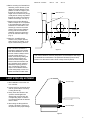
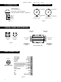
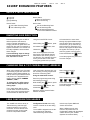
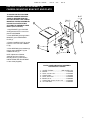
SHEET NO. 11042600
REV. 03
9/00
SEC. 01
DCS SYSTEM ROBOTIC POSITIONER
PRO/ FOUR
TM
VIDEO PRODUCTS, INC.
MODEL 1010RP USER’S GUIDE
15 POUND RATED
DCS SYSTEM ROBOTIC
POSITIONER
•
•
•
•
•
Studio Silent Operation
On-Board Receiver
Internal Cabling
Status Indication
Lens Header
PRODUCT
DESCRIPTION
The Model 1010RP is a second generation version of Pro/Four’s silent
precision Model 1000RP Robotic
Positioner. This new offering features
an on-board receiver, combined with
internal cabling for camera power,
video, and command signals for both
positioner and zoom lens. The unit
simplifies setup and operation through
the use of status indicator lights and
mounting orientation programming.
IMPORTANT INSTRUCTIONS - PLEASE READ CAREFULLY BEFORE INSTALLING OR OPERATING EQUIPMENT
PRO/FOUR’S UNIQUE DCS
ROBOTIC CONTROL SYSTEM
HAS BEEN ENGINEERED TO
PROVIDE YEARS OF TROUBLE FREE OPERATION. YOUR
FAMILIARITY WITH THE SYSTEM WILL PROVIDE YOU WITH
FULL KNOWLEDGE OF IT’S
CAPABILITIES.
CAREFULLY READ THE
REMAINDER OF THE INFORMATION CONTAINED IN THIS
MANUAL. IF YOU ARE FULLY
AWARE OF PROPER INSTALLATION AND OPERATION OF
THIS EQUIPMENT IT WILL
SERVE YOU WELL.
1. Before opening the shipping carton check for any visible damage to the
box.
2. If damage is seen, open the shipping carton, remove the unit and check
for any visible damage to the unit.
3. If any question as to the possibility of damage exists, notify your dealer
or Pro/Four at once.
4. Remove the plastic accessory bag from the carton. It should contain the
following:
1
1
1
1
2
2
2
1
1
1
1
1
- Distribution Module
- Camera Mounting Screw
- Hex Key
- Camera Power Connector
- Video Connector
- Data/Power Connector RJ45
- Data Connector (RJ-11)
- 3 In Data Jumper
- 6 In AC Power Jumper
- 18 In Video Cable (RG-59)
- Camera bracket assembly
- Camera Power Connector
4080DM (incl. pwr. cbl. No. 283000C)
(Part No. 61564008)
(Part No. 69010600)
(Part No. 18044000)
(Part No. 18044100)
(Part No. 18044200)
(Part No. 18044700)
(Part No. 282000C)
(Part No. 286000C)
(Part No. 285000C)
(Part No. 11028000)
(Part No. 18044300)
OPTIONAL MOUNTING ACCESSORIES
Model 4220L Camera Leveler
Model 4000W Wall Mount
Model 4100T Tripod Mount
Model 4050P Accessory Base Plate
Model 4075C Column Mount
CAUTION
The Model 1010RP Robotic Positioner must be installed in conformance
with all applicable code requirements, local, state, and national.
SHEET NO. 11042600
REV. 03
9/00
SEC. 01
INSTALLATION
IMPORTANT - PLEASE NOTE:
The unit has a label marked
“FRONT” on the Camera
Platform. The camera should be
mounted facing toward the
“FRONT” label in order to function properly with the Controller.
A travel limit of 330 degrees protects the unit from windup of
cables. A center of travel mark
has been inscribed on the Base
and Body to indicate where the
unit is at any time. When shipped
from the factory the unit is positioned with the two indicators in
line, the center of travel limits.
The Model 1010RP is not orientation sensitive. It may be mounted either upright
or inverted. Before attempting to install the unit refer to Figure 1 to become
familiar with it’s design and adjustments. Refer to “Inverting Axis Direction”
The Following Methods of mounting maybe employed:
1) Base mounting Using the four 1/4-20 threaded holes on the Base to
attach directly to a horizontal surface.
2) Surface mounting - Using a PRO/FOUR Model 4050P Accessory Base
Plate which may, in turn, be mounted to a horizontal
surface for either upright or inverted mounting.
3) Wall mounting Using a PRO/FOUR Model 4000W Wall Mount
which, in turn, may be mounted on any suitable vertical surface.
4) Tripod mounting - Using a PRO/FOUR Model 4100T Tripod Adaptor
which may be mounted to a tripod using either a 1/4
inch or 3/8 inch thread adapter.
5) Column mounting - Using a Pro/Four Model 4075C Column Mount which
may be oriented either upright or inverted.
Note: Templates are supplied with the unit and accessories to locate
mounting holes.
CAMERA / LENS MOUNTING
Before installation of the Positioner Assemble the Camera and Lens. Of
the two units, the Lens is often heavier and wider than the Camera.
To insure best performance of the
1010RP follow the following steps.
1. After assembling the Lens and
Camera (see Fig. 1), note the gap
between the mounting surfaces
and 1/4-20 thread mounting holes
of both. It is sometimes advisable
to mount the Camera/Lens
assembly to a Model 4220L
Camera Leveler to best mount to
the 1010RP. (See Accessories)
Gap
Figure 1
2. If a Leveler is selected, assemble the
Camera and Lens in accordance
with the instruction provided with the
Model 4220L Unit.
3. If a Leveler is not considered necessary, remove the Camera
Mounting Platform using Hex Key
69010600 (supplied).
4. Loosely attach the Camera assembly using the 1/4-20 Screw
61564008 (supplied).
5. Using a round object, such as a
pen or pencil, locate the front to
back point at which the Camera/Lens assembly most closely balances. Lock the Mounting Screw
at this point. This is the location
which should be over the center of
the Camera platform (CG) mounting hole. (see Fig. 2).
2
1/4-20 Screw
Camera Mounting Platform
Round Object
Figure 2
SHEET NO. 11042600
REV. 03
6. Before mounting the Camera/Lens
Assembly, loosen Screws (1) and
adjust the Vertical Position of the
platform so that an imaginary line
through the center point of the
height of the Camera/Lens pair (A)
would pass as closely as possible
through the center of the Camera
Platform Tilt axis (B). (see Fig. 4).
9/00
SEC. 01
Width Clearance
C
7. Remount the Camera Mounting
Platform. Adjust the In-out position
to accommodate the width of the
Camera/Lens combination. Lock
Screws (2) to secure the In/Out
position of the Camera Platform,
insuring that the Camera/Lens
assembly clears the vertical portion of the Camera Platform (C).
(Fig. 3).
A
Height
Adjustment
B
8. Mount the 1010RP with the
Camera in the position desired,
again noting that “FRONT” is facing the camera aiming direction.
(2)
(1)
Note: The above procedure is
intended to balance the Camera
load. Most installations are such
that the Camera is always aimed
at some position close to, or
below, horizontal. By shifting the
Camera slightly forward, the
Positioner load is always maintained in the same direction and
any: “backlash” in the system is
eliminated, improving the accuracy of positioning. This technique is recommended whenever the aiming range is close to or
below horizontal to further down.
Figure 3
The Camera Platform has been designed to accommodate a wide range
of Camera/Lens combinations. The preferred Horizontal (front to back)
location is at the same location found in steps 4 and 5 (above).
LIMIT STOP ADJUSTMENT
Tilt Limit Stops
1. After installation connect the unit
to a controller.
2. Loosen both Pan (horizontal drive)
and Tilt (vertical drive Limit Stop
Locking Screws (3).
3. Slowly rotate the camera to the
up/down and left/right limits
desired and move and lock the
corresponding stops so that the
Limit Stop actuates at the desired
limits of travel.
4. After locking the Stop positions
recheck, first slowly, and then at
full speed to insure proper settings.
Pan Limit Stops
Figure 4
3
SHEET NO. 11042600
REV. 03
9/00
SEC. 01
WIRING
NOTE: The 1010RP has been
designed to operate with
Pro/Four’s DCS Digital Control
System. The 1010RP will operate with systems designed to
communicate using Pro/Four
protocol. An intermediate
module which converts RS-232
to RS-485 is available which
will permit the 1010 to operate
from PC generated control
commands. Pro/Four does not
assume any responsibility for
operation or safety of controls
other than Pro/Four units without the express written confirmation or approval by
Pro/Four. Refer to Wiring
Diagram for System wiring.
Control Connection
Refer to Fig. 5
The unit has been designed to operate with the Model 2100 Control. The
Control system has been designed
for maximum flexibility of location.
The DCS System permits data transmission over distances up to 2000
feet. The Data/Power separation permits distances up to 250 feet. Refer
to the appropriate Control for
Installation instructions.
Cable Harness
Reduction
The 1010RP has been designed to
simplify Cabling and to eliminate
Cable Dressing problems. Provision
has been made for all cables to enter
through the unit’s stationary base,
eliminating the need for allowance for
cable movement.
PAN/TILT POWER and DATA COMMAND SIGNALS are routed through
a single cable. CAMERA POWER
may be routed through a Mini DIN
type connector (provided). VIDEO
may be routed through BNC type
connectors (supplied).
The LENS CONTROL connector is
located on the upper portion of the
1010RP. Most Teleconferencing
Lenses provide sufficient cable
length to reach this location. Pro/Four
has additional cables available if
greater length is required.
SYSTEM INTERCONNECTION (REFER TO FIG. 5)
The 4080DM DISTRIBUTION MODULE serves as a distribution point for
DATA AND POWER. Data signals
loop through the DISTRIBUTION
MODULE and permit daisy chain
system setup. AC POWER for
Distribution Modules may be looped
4
through from one module to the next.
Provision is made to attach modules
to each other, eliminating need for
component cages, and creating a
single package look. An AC POWER
JUMPER (P/N 286000C) is provided
with each 4080DM for this purpose.
The most efficient wiring normally
occurs with placement of the 4080DM
in close proximity to the 2100 Control
Unit. DATA/POWER is then route as a
single cable to the 1010RP location.
SHEET NO. 11042600
REV. 03
9/00
SEC. 01
WIRING THE SYSTEM (Bold Numbers refer to Fig. 5)
POWER in accordance with each
Camera manufacturers’ Power Supply
for their Camera. Pro/Four supplies a
CAMERA POWER CONNECTOR
(P/N 18044000) for termination at the
1010RP (See Fig. 7).
4080DM
Distribution Module
(6) DATA – The DATA Cable is the
connection from the 2100 Control to
the 4080DM.
(2) VIDEO OUT – (customer furnished) Pro/Four supplies a BNC
CONNECTOR (18044100) with each
1010RP for Video wiring. Output
Video is routed from the Base to
Customer equipment. (See Fig. 8).
NOTE: DATA CABLES ARE AVAILABLE FROM PRO/FOUR – (Cable
284XXXC). Pro/Four also supplies a
9 PIN D SHELL to RJ11 ADAPTER
with each 2100ARUC Controller to
facilitate interconnection between
the 2100 unit and the Data Cable
(P/N 18044600).
Interconnect Panel
(8) VIDEO IN – is an 18 inch JUMPER
CABLE (285000C) furnished with the
1010RP, connecting Camera Video to
the Interface Panel.
Base Input Panel
(3) DATA/POWER – The
DATA/POWER Cable is the connection from the 4080DM to the 1010RP
Base Input Panel. (See Fig. 6).
(10) CAMERA POWER – (customer
furnished) is a JUMPER CABLE, terminated at one end with a CONNECTOR – P/N 18044000 (supplied)
which attaches at the Interface
Panel and is terminated at the
Camera, using the Connector supplied by the Camera manufacturer.
NOTE: DATA/POWER CABLES
ARE AVAILABLE FROM
PRO/FOUR – (Cable 281XXXC).
(1) CAMERA POWER – (customer
furnished) is wired from LOCAL
4080DM
Module
(Supplied with 1010RP)
NOTE: The 1010RP Interface Panel
contains a Plug-In HEADER. The
Header is internally wired to conform with wiring of the make and
model Lens being used. Since
Lenses may be wired differently,
Pro/Four offers a series of Headers
wired to insure proper operation
with the 1010RP. The 1010RP is
factory supplied with a Header
wired for the CanonKTS and
Fujinon BMD Teleconferencing
Lenses. (P/N 29POOOH).
(9) LENS CONTROL – is normally
connected to the Interface Panel
using the Lens Cable (part of the
Lens). Length dictates whether
Pro/Four extra Cable (Series
29XXXXC) is required. Lens make
and Model Number determine need
for a Header. The Lens Control
Cables are supplied as Cable only,
Header only, or Cable plus Header,
based on this criteria. See 1010RP
Systems Connections Sheet for listing of Lenses and Headers. See Fig.
9 for Lens Cable wiring.
Power 5
(Supported with 4080DM)
2100RCTD
Control
Lens
Data 6
1010RP
Positioner
Header
Data
Camera Power Jumper 10
Camera
Camera Power 1
Power
4420PP
(Shipped with 2100RCTD)
Video 8
Lens Control 9
1010RP Supplied
Data/Power 3
Available from PRO/FOUR
Customer Supplied
Video Out
2
Figure 5
5
SHEET NO. 11042600
REV. 03
9/00
VIDEO FEED-THROUGH
I/O CONNECTORS
RJ45 Connector
(8 Pin Modular plug)
+++
BA
SEC. 01
Video Signal
Video Signal
Power input: 15-30 VDC @15W
Data input: EIARS - 485 (120Ω impedance)
–––
Power (–)
Data (A)
Data (B)
Power (+)
Video Ground
Video Ground
Video Feed In
Video Feed Out
Standard BNC - RFConnector
Standard BNC - RFConnector
Figure 6
Figure 8
CAMERA POWER FEED-THROUGH
Camera Power
Feed-In
A
A
C
Camera Power
Feed-Out
C
B
B
A
Camera Power
Feed-In
Camera Power
Feed-Out
Camera Power
Feed-In
B
C
Figure 7
Mini DIN Jack
Adam Tec MDJ-003
(1A Max)
Camera Feed-Through A
Camera Feed-Through B
Camera Feed-Through C
Pan/Tilt Unit
Rated 30V AC/DC @ 1 AMP
LENS CONNECTION
End View
9
10 8
3 11 12 7
HRS
6
4
5
1
2
HRS HR10-R-12PS
Zoom Signal
Focus Signal
Iris Signal
(+V: Tel) 9
(+V: Far) 8
(+V: Open) 5
COM +V
(7.5V) 11
+V: Position
Zoom Position/Speed Select ( ∞: Speed ) 2
+V: Position
Focus Position/Speed Select ( ∞: Speed ) 1
Position
( +V:
Iris Position/Speed Select
∞: Speed ) 10
(2.5V) 12
COM -V
Manual
( 0V:
∞: Auto ) 4
Auto Iris Enable
+12V
(12V) 6
OV
COM
(9V) 3
(5V) (Not Used) 7
Figure 9
6
A
B
Camera Power
Feed-Out
C
Mini DIN Jack
Adam Tec MDV-003
(1A Max)
SHEET NO. 11042600
REV. 03
9/00
SEC. 01
1010RP ENHANCED FEATURES
DEVICE STATUS INDICATORS
● Light Off
● Light On
Light Blinking
Device Status:
● Driver Is Not Running
● Driver Is Running
Device Power:
● Unit Is Not Receiving Power
● Unit Is Receiving Power
Device Data:
● Unit Is Not Receiving Data
● Unit Is Receiving Data
Unit Is Receiving Data and
Is The Current Selected Camera
INVERTING AXIS DIRECTION
Sometimes mounting the 1010RP in
different positions will cause its
motion to appear “backwards.” I.e.
hanging the Pan/Tilt upside down will
cause both Pan and Tilt movement to
appear “backwards.” The 1010RP can
be easily adjusted to accommodate
these changes.
Use the following steps to change
the normal direction of motion on
Pan, Tilt, Zoom or Focus.
Using the 2100 RCTD Control:
While holding the
and release the
release the
STO
STO
PGM
IRIS AM
Button, press
Button, then
Button.
Now move the joystick so that the
axis moves in the desired direction.
Note that the axis will only move in
one direction. For example: Since the
tilt only moves down in this mode,
moving the joystick both up or down
will cause the tilt to move down.
Moving the joystick DOWN will program tilt down when the joystick is
moved down. (Tilt up when the joystick is moved up.) Moving the joystick UP will program tilt down when
the joystick is moved up. (Tilt up
when the joystick is moved down.)
Press and Release the
STO
Button
to end the programming mode and
store the changes.
CHANGING PAN & TILT CAMERA SELECT ADDRESS
When using multiple Pan & Tilt units it
is necessary to give each unit its own
separate Camera Select Address; so
that the units may be selected individually. Each unit is shipped from the
factory with the address CAMERA
GROUP 1, CAM 1.
units connected to the buss thus only
the unit being currently programmed
should be on/receiving data.
Select Camera Group by
pressing A or B .
CAMERA
GROUP
CAMERA
GROUP
Using the 2100 RCTD Control:
Enter the programming mode using
the following procedure:
To change the Pan & Tilt Camera
Select Address complete the following steps:
While holding the
and release the
PGM
First, unplug either data or power
from all other receivers and Pan/Tilt
Units on the buss. Programming the
Camera Select will affect all other
release the
Button.
STO
STO
IRIS AM
Button, press
Button, then
Select Camera by pressing
2
, 3 or 4 .
CAM
CAM
1
CAM
,
CAM
Press and Release the STO Button
to end the programming mode and
store the changes.
Select the desired Camera Select
Address as follows:
LENS CONFIGURATION HEADER
The 1010RP can drive a variety of
Teleconferencing and ENG type
lenses through the Lens Control
Connector. To insure that the lens
receives its proper control format,
Pro/Four has provided a Lens
Configuration Header that configures the controller to the lens being
used.
The 1010RP is shipped from the factory configured for Standard
Teleconferencing Lenses these
include most Fujinon BMD and
Cannon KTS lenses.
When a different lens is used,
Pro/Four will provide the Lens
Configuration Header with the adapter
cable to the lens. (See 1010RP
Systems Connections Sheet).
7
SHEET NO. 11042600
REV. 03
9/00
SEC. 01
5.60"
11.25"
8.00"
SPECIFICATIONS
Mechanical
Size ..... Height ................
Width ................
Depth ................
Weight ..............................
Camera Mounting Adj. ..
Width ................................
Height ..............................
Front/Back ........................
Camera/Lens
Mounting Hole Spacing ..
Angular Travel ..................
Pan ..................................
Limit Stops ......................
Unit Mounting ..................
Construction ....................
Drive ................................
8
8.00 inches
5.60 inches
11.25 inches (Includes Camera Support)
6 lbs. (6-1/2 lbs with 4220L)
Three axis
Standard
4220L
0.80 inches
2.60 inches
1.75 inches
1.75 inches
2.50 inches
3.25 inches
3.00 inches to 6.25 inches
Tilt - +/- 90 degrees
Approx. 330 degrees
Externally Adjustable for
Vertical and Horizontal travel
Easily accessible with the
camera and lens in place.
3-3/4 inch diameter base with
two 1/4-20 screws 2 inches on center.
Cast vinyl coated aluminum
housing. External aluminum parts
anodized for outdoor use
non-aluminum parts stainless steel.
Precision worm gear.
Electrical
Voltage ..............................
Power Consumption ..........
Power Input ......................
Data Input ..........................
Camera Power Feed-Thru ..
15-30 volts VDC
15 watts
RJ-45
EIA RS-485 (120Ω impedance)
1 Amp AC/DC (30V max.)
Operational
Operating Speeds ..............
............................................
............................................
............................................
Maximum Load ..................
Preset Accuracy ................
Pan (horizontal) 0-15
degrees/second
Tilt (vertical) 0-15
degrees/second
15 pounds
+/- 20 arc minutes
SHEET NO. 11042600
REV. 03
9/00
SEC. 01
INSTRUCTIONS FOR ASSEMBLY OF
CAMERA MOUNTING BRACKET AND PLATE
TO INSURE PROTECTION FROM
SHIPPING DAMAGE THE MODEL
1000RP IS SHIPPED FROM THE
FACTORY WITHOUT THE CAMERA
MOUNTING SYSTEM ASSEMBLED.
PLEASE FOLLOW THE STEPS
OUTLINED TO ASSEMBLE THESE
PARTS. (See illustration)
SLOT
PIN (2)
3
4
1. Align BRACKET (2) so that PINS
are aligned with SLOT in round front
plate of POSITIONER.
2. Insert SCREWS (3) through slots in
BRACKET (2) into POSITIONER
PLATE (1).
3. Position CAMERA PLATE (4) so that
holes are in line over slots in BRACKET (2).
4. Insert SCREWS (5) and washers (6)
through slots in BRACKET (2) into
CAMERA PLATE (4).
1
6
8
7
6
5
2
NOTE: Adjustment of Bracket
Assembly and use of Camera
Mounting Screw (7) is described in
INSTALLATION AND ADJUSTMENT
in User Guide (Supplied).
1010RP CAMERA MOUNTING ASSEMBLY
PRO/FOUR P/N 11028000
1
2
3
4
5
6
7
8
- 1010RP Tilt Plate ....................(ON 1010RP Unit)
- Bracket..................................................11031100
- Screw, 1/4-20 x 3/8 ..............................61501006
- Camera Plate........................................11031200
- Screw, 8-32 x 3/8..................................61322406
- Washer, No 8 ........................................63300000
- Camera Mtg. Screw, 1/4-20 x 1/2 ........61564008
- 1/4 in flat wash......................................63500000
9
SHEET NO. 11042600
REV. 03
9/00
SEC. 01
OPERATION
(Refer to Service Manual for the Control)
MAINTENANCE
The Model 1010RP has been
designed to eliminate the need for
periodic maintenance. Lubrication for
all moving parts is permanent.
Motors, switches, and other moving
parts are rated in excess of normal
expected operating life of the unit. DO
NOT attempt to open the unit to
make any adjustments or repairs.
Unauthorized repairs or adjustments
may void the Pro/Four warrantee. In
the event that an operating problem
occurs contact your dealer or
Pro/Four Video Products, Inc.
SERVICE
If Failure Occurs: CALL PRO/FOUR OR YOUR DEALER
PRO/FOUR equipment is warrantied for a period of One (1)
year from date of first sale. In the
event of failure of equipment to
properly operate, PRO/FOUR
maintains a technical service
HOTLINE to assist in returning
the faulty unit (s) to service with
the least possible delay.
CALL PRO/FOUR at 1- 800-254-6573 any time within the hours of 9:00 AM
to 5:00 PM (EST), Monday through Friday.
A Service Specialist will take your call and attempt to solve the problem over
the telephone. If the Specialist is unable to resolve the problem, you will be
issued a RETURN AUTHORIZATION NUMBER, and instructions for return of
the faulty unit(s).
UNDER NO CIRCUMSTANCES RETURN EQUIPMENT WITHOUT A
RETURN AUTHORIZATION AS DESCRIBED ABOVE. The PRO/FOUR warrantee specifically excludes equipment returned with no Return Authorization
Number from warrantee coverage.
IMPORTANT INFORMATION
When requesting information, supplies, or service always refer to the model and serial number of your unit. The model
and serial number”s plate (Main Name Plate) is located on the bottom of the machine.
For your convenience, space is provided below to record the information you may need in the future.
MODEL NO. 1010RP
SERIAL NO.
Dealer
City
Date of Purchase
Address
State
Supplies Telephone
Zip
Telephone
Service Telephone
PRO/FOUR VIDEO PRODUCTS, INC. 2131 Sunnydale Boulevard, Clearwater, FL 33765
Telephone 727-447-6389 • FAX 727-442-2461 • 800-457-8130 • E-Mail [email protected]
© 1999 by PRO/FOUR, INC. All rights reserved. Printed in USA
The contents of this User’s Guide are subject to change without notice.