1
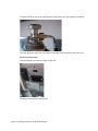
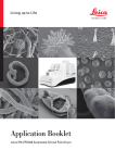
Leica EM CPD300
Operating Manual
167180032 Version 06/2012
Important Note
tinuously improve the technology and manufacturing techniques used to provide our
!
"
!
!
#$
"
!!
%
&
##
!%!
!!&
'
Issued by:
Leica Mikrosysteme GmbH
Hernalser Hauptstrasse 219
A-1170 Vienna
Leica EM CPD300
2SHUDWLQJ0DQXDO
Leica EM CPD300 Serial Number:
Date of purchase:
For the instrument serial number, please refer to the name type label on the
back of the instrument!
Please read this instruction manual carefully
before operating the instrument.
Foreword
This technical documentation is intended to provide essential information about the
proper operation and servicing of the Leica EM CPD300 critical point dryer.
Service and operating staff must familiarize themselves with all components of the
system before commissioning. Particular attention must be paid to the aspect of
safety.
Please retain this operating manual for future reference.
Texts, schedules and tables may not be copied, reproduced, or divulged to third
parties without the express consent of Leica Microsystems.
In addition, all generally applicable legal and otherwise binding regulations for
preventing accidents and protecting the environment must be observed by the user
and communicated to all users.
Page 1 Operating Manual Leica EM CPD300 06/12
Table of contents
1. Introduction ..............................................................................................................................3
2. Safety.........................................................................................................................................4
2.1 Safety concept of Leica Mikrosysteme GmbH....................................................................4
3. Installation and Warranty ........................................................................................................6
3.1 Installation............................................................................................................................6
3.2 Warranty ..............................................................................................................................8
4. Method.......................................................................................................................................9
4.1 Critical Point Drying Method................................................................................................9
5. Description and Specification ..............................................................................................11
5.1 Technical specifications ....................................................................................................11
6. Preparation of Specimens.....................................................................................................12
7. Automatic Operation of EM CPD300....................................................................................13
7.1 Screen descriptions...........................................................................................................13
7.2 Programming by example .................................................................................................17
7.3 Programming the EM CPD300 procedure ........................................................................26
7.4 Filling the Sample Chamber with exchange fluid..............................................................26
7.5 Inserting Specimen into Sample Container ......................................................................26
7.6 Preset of Cooling Temperature of the Sample Chamber .................................................27
7.6.1 CO2-Bottle Temperature / Pressure Function .............................................................27
7.7 Starting the EM CPD300 auto procedure .........................................................................28
7.8 Time and timer function.....................................................................................................28
8. Manual Operation of EM CPD300 .........................................................................................33
8.1 Screen descriptions...........................................................................................................33
8.2 Filling the chamber with exchange fluid............................................................................35
8.3 Inserting of Specimen into Sample Chamber ...................................................................35
8.4 Cooling of the Sample Chamber .......................................................................................35
8.5 Filling the CO2 into Sample Chamber ...............................................................................36
8.6 Mixing the two liquid media ...............................................................................................36
8.7 Exchange media mixture from Sample Chamber.............................................................36
8.8 Heating the Sample Chamber...........................................................................................37
8.9 Releasing gaseous CO2 from Sample Chamber ..............................................................37
9. Removing Dried Specimen ...................................................................................................37
10. Switching off the Unit ............................................................................................................37
11. Setting Panel...........................................................................................................................38
12. CO2-Bottle Temperature / Pressure Function .....................................................................39
13. Adjustments of Pressure Threshold for Bottle Empty Function......................................40
14. Software Update .....................................................................................................................43
15. Service Notes..........................................................................................................................45
15.1 Gas-Out filter maintenance ...............................................................................................45
15.2 General maintenance ........................................................................................................46
16. User Maintenance ..................................................................................................................47
16.1 Poral filter replacement .....................................................................................................47
16.2 Cleaning.............................................................................................................................49
17. Warnings and Troubleshooting............................................................................................49
Page 2 Operating Manual Leica EM CPD300 06/12
1.
Introduction
In order to ensure the safety of service technicians and operators, and to prevent any
damage to the Leica EM CPD300 critical point dryer, it is essential to carefully read
this manual before beginning any work with the system.
This Operating Manual is intended to help the user understand the system more
completely, to use it within the specified limits of its working capabilities, and to
maintain in accordance with its physical parameters.
This user manual includes important information regarding proper installation,
operation, troubleshooting and repair. Following these instructions will help to prevent
hazards, reduce repair and downtime costs, and prolong the system's service life.
Symbols in this manual and their meaning:
Danger!
All paragraphs in the Technical Documentation that contain instructions
regarding possible hazards are identified with this symbol.
Non-observance these alerts may result in serious injury! Users of the
instrument must comply with instructions at all times.
Caution!
This symbol alerts the user to important information which may endanger staff
or result in damage to the system if it is ignored.
Note!
This symbol indicates further information relating to a previous explanation,
which does not have a safety-critical function. However, it is important to
follow this information to ensure that the system functions optimally.
Page 3 Operating Manual Leica EM CPD300 06/12
2.
Safety
Warning!
The EM CPD300 critical point dryer can be operated simply and safely, if the
system is operated according to the operating manual.
2.1
Safety concept of Leica Mikrosysteme GmbH
The use in accordance with regulations of the EM CPD300 critical point dryer
consists of critical point drying of biological or industrial samples with minimal
deformation of the specimens for subsequent SEM analysis.
Any other application without written approval of the manufacturer can lead to
damages and injuries of instrument and user. The manufacturer refuses to take any
responsibility for damage caused thereby.
The sample pressure chamber with a maximum working pressure of 150bar is
secured with a Software and Hardware Cut Off function.
Hardware controlled cut off
Bursting membrane at 105bar at 20 °C (+/-10%)
Software controlled cut off
Pressure at 80bar and temperature at 45°C
For safe operation it is absolutely necessary to set up and connect the device
according to the instructions in Chapter 3.
Page 4 Operating Manual Leica EM CPD300 06/12
General safety regulations
Generally, the following safety regulations apply to the handling of the EM CPD300
critical point dryer:
x
Every user is responsible for her / his own health.
x
Only instructed users, authorized by the customer are allowed to work at or
with the system.
x
For all interaction with the EM CPD300 the user must wear protective clothing
prescribed in the respective environment.
x
It is strictly prohibited to alter or remove protective equipment or covers of any
kind.
x
Every user must be trained in safe handling of the process gases and fluids
that are utilized in the EM CPD300 unit.
x
After every repair the user (technician) must verify a flawless state of the
system by a test run.
x
Leica can guarantee full operation of the system only if original spare parts
according to the part lists are used.
x
Careful operation and preventive maintenance of the EM CPD300 reduces
maintenance costs and assures reliable operation.
x
By means of frequent checks and prompt rectification of even small damages,
considerable damage can often be avoided.
x
Observation of this operating manual and all notes installed on the system
serves your own safety.
Page 5 Operating Manual Leica EM CPD300 06/12
3.
Installation and Warranty
3.1
Installation
Required space for setting up the unit: width 340 mm, depth 583 mm.
Operating room temperature:
20 – 35C° at 1bar (CO2 bottle limit)
Relative humidity:
5 – 90%
To allow adequate intake of cooling air required for the refrigeration unit and due to
the inflexibility of the high pressure gas hose, a free space of 150 mm has to be
provided on the backside of the instrument.
Connection of CO2 Container
It is absolutely necessary to use a pressurized gas container with a pipe (feed pipe),
so that the medium (CO2) can reach the specimen pressure chamber in liquid form.
In order to prevent accidents the CO2-pressurized gas container must be
securely fastened in an upright position.
Screw the high pressure gas hose onto the CO2 IN connection.
Page 6 Operating Manual Leica EM CPD300 06/12
Connect the other end of the high pressure gas hose to the gas pressure container.
The high pressure gas hose and seal are included in the accessory set of the unit.
Electrical Connection
Check assigned connecting voltage of the unit.
Connect power cable to wall socket.
Page 7 Operating Manual Leica EM CPD300 06/12
3.2
Warranty
The EM CPD300 is covered by a WARRANTY in accordance with the conditions of
sale. If functional errors should occur or if the components of the system sustain
damage that is subject to warranty coverage during the warranty period, the
manufacturer will repair or replace the faulty components following examination
thereof.
The manufacturer warrants for the system in its original configuration.
Only original replacement parts may be used. The manufacturer accepts no liability
for damage caused by use of other replacement parts.
Caution!
The environmental conditions that were agreed contractually and determined at
the time of installation must be maintained.
The manufacturer will not accept liability for damage caused by misuse of the system
or its use for purposes other than the intended use, nor for damage caused by work
on the system that is not described in this manual.
Page 8 Operating Manual Leica EM CPD300 06/12
4.
Method
4.1
Critical Point Drying Method
Drying water-containing biological and material specimens in air or under vacuum
can drastically alter their structures or even destroy them completely by tangential
forces, caused by surface tension of the water (A).
The surface tension is a quality of surfaces between a liquid and a gas and the
tangential forces appears by boundary crossing from liquid to gaseous phase.
Phase diagram
P (bar)
solid phase
supercritical fluid
liquid phase
B
Pc
C
Pt
A
gaseous phase
T (°C)
Pc = Critical Point
Pt = Triple Point
A = Air drying (phase boundary crossing)
B and C = Critical point drying (no phase boundary crossing)
Page 9 Operating Manual Leica EM CPD300 06/12
For biological and most micro-electro-mechanical (MEM) samples, critical point
drying cannot be performed with water. Water’s critical point is at 374°C and
228.5bar. Every biological and MEM sample would be destroyed at this temperature
and pressure. Therefore, the use of CO2 as transitional fluid is the first choice for
critical point drying. It is liquid at room temperature at a comparative low pressure of
60bar. Its critical point is at 31°C and 73.8bar. Technically these temperature and
pressure requirements of the CO2 can be implemented relatively easily. Hence, the
water in the cell is replaced by an exchange medium like acetone or ethanol, which
unlike water, are very soluble with liquid CO2. After the replacement of the water by
an exchange fluid, this exchange medium is substituted with liquid CO2 through serial
dilution steps. Thereafter by increasing the temperature, the pressure is increased
proportionally and will transfer the CO2 through its critical point into a supercritical
state (B). At constant temperature the controlled and carful depressurization converts
the supercritical CO2 into its gaseous phase without crossing the phase boundary
between liquid and gas (C). After coating, the dried sample can be analyzed in a
scanning electron microscope (SEM).
Comparison between air and critical point drying:
Critical point dried sample (Water flea)
Air dried sample (Water flea)
Page 10 Operating Manual Leica EM CPD300 06/12
5.
Description and Specification
Introduction
Biological specimens intended for investigation in a scanning electron microscope
must be dried before being introduced into the microscope to allow the specimen to
be imaged. If specimens with water content are dried, tangential forces, caused by
surface tension of the water, destroys the structures of the specimen as mentioned in
the previous chapter.
Critical point drying with the EM CPD300 is the optimal method to prevent the
damaging effects of the above mentioned forces by bringing the liquid to the gas
phase without boundary crossing.
5.1
Technical specifications
Dimensions:
Weight:
Empty weight
31 kg
Sample chamber:
Chamber dimension
Volume
Ø 60 mm x 62 mm
185 ml in empty chamber
Pressure:
Safety bursting membrane
Software controlled cut off
Max. operating pressure
(Software controlled)
Temperature:
Heating range
Software controlled cut off
Heating time Slow
Heating time Medium
Heating time Fast
Page 11 Operating Manual Leica EM CPD300 06/12
105bar at 20 °C
80bar
79bar
adjustable
>45°C
1°C/min.
2°C/min.
3°C/min.
(+/-10%)
30°C to 45°C
Cooling
Cooling capacity
Refrigerant
Quantity
Cooling range
Cool down time
90 W at -5°C (2500 1/min)
R134a
120 g
adjustable
5°C to 25°C
2.0°C/min.
Electrical Connection:
Voltage
Frequency
Power consumption
100 V -230 V
50 / 60 Hz
170 VA
Gas Connection:
Gas inlet
Gas outlet
M 12 x 1.5
Ø 8 mm (inner diameter)
Requirements
Transitional fluid: Carbon Dioxide (chemical formula CO2)
CO2 pressure bottle with feed pipe
Exchange fluid: Acetone, Ethanol
6.
Preparation of Specimens
Wash in a physiological salt solution.
Fix chemically with a suitable fixing agent.
Wash out fixing agent with a suitable buffer solution.
Dehydrate the chemically fixed specimen with acetone or ethanol.
(Protocol examples are shown in the EM CPD300 Application booklet).
Page 12 Operating Manual Leica EM CPD300 06/12
7.
Automatic Operation of EM CPD300
7.1
Screen descriptions
Initialization screen: Touch screen after initialization.
Main Screen:
14
15
1
8
9
2
3
10
7
11
12
4
5
6
13
Dark gray buttons can be activated, light gray buttons are inactive!
Page 13 Operating Manual Leica EM CPD300 06/12
1
Version of the EM CPD300.
2
Switch to program panel (see page 15).
3
Status display of fillers and holder in the sample chamber.
Programmable under programs.
4
Status display temperature, pressure and time to finish the process
(last point only with auto function).
5
Switch to settings (see page 37).
6
Light on/off
7
Status display of programmed process.
In auto version buttons have no function.
8
Cooling temperature to keep CO2 fluid (can be changed under settings, page 37).
9
CO2 influx speed in pressure chamber.
Programmable under programs.
10 Exchange speed (1-10) and status of finished exchange cycles.
Programmable under programs.
11 Heating speed and heating temperature for critical point.
Programmable under programs.
12 Status display gas out speed.
Programmable under programs.
13 Process start. (after defining program).
14 Timer function (see page 27).
15 Program name of activated program (see page 15).
Page 14 Operating Manual Leica EM CPD300 06/12
Programm Screen / Panel:
1
2
3
4
5
6
7
8
9
10
11
13
1
Activates key pad to enter program name.
2
Activated program is marked green.
3
Stirrer on / off with speed control.
4
Activation of auto version. If not highlighted manual version is active.
Only selectable in automated version.
5
Sets speed of CO2 influx in pressure chamber.
Three possibilities: slow, medium, fast.
6
Switch to filler and holder panel. Display of filler and holder status.
7
Sets delay time after influx of CO2 and before starting exchange process.
8
Sets exchange speed from 1-10.
9
Sets exchange cycles. 12 cycles means one chamber volume is completely
exchanged. Minimum is 12 cycles.
10 Sets heating speed for critical point. Three possibilities: slow, medium, fast.
11 Sets gas out speed. Possibilities: slow, medium, fast.
Slow speed can be decreased up to 20% of its normal speed.
12 Scrolls programs from 1-10.
13 Confirms activated program. Switch to main screen.
Page 15 Operating Manual Leica EM CPD300 06/12
12
Filler/Holder Panel:
1
2
3
4
1
Filler and holder panel.
2
Status display of fillers and holders.
3
Sets specific holder and fillers. Combination of holders and fillers depends on
their volumes.
4
Confirms filler and holder setting.
Page 16 Operating Manual Leica EM CPD300 06/12
7.2
Programming by example
Press Programs
Press Program
Name
Type program
name
Page 17 Operating Manual Leica EM CPD300 06/12
Press OK to
confirm program
name
Activate Stirrer
Select stirrer
speed
Speed display
will disappear
after 4 sec.
Page 18 Operating Manual Leica EM CPD300 06/12
Activated Stirrer
Symbol becomes
green
Set CO2-IN speed
Example:
from slow to fast
Press Fillers
Program
Filler/Holder
combination
Example:
1/2 Holder with
1/6 and 1/3 Filler
Page 19 Operating Manual Leica EM CPD300 06/12
Press OK to
confirm
Filler/Holder
settings
Press Delay
Set Delay Time
Example:
changed from
120s to 100s
Page 20 Operating Manual Leica EM CPD300 06/12
Press OK to
confirm
Press Exchange
Speed
Set Exchange
Speed
Example:
from 5 to 7
Page 21 Operating Manual Leica EM CPD300 06/12
Exchange Speed
display will
disappear after 4
sec.
Press Exchange
Cycles
Set Exchange
Cycles
Example:
from 16 to 12
Page 22 Operating Manual Leica EM CPD300 06/12
Press OK to
confirm
Set Heating
Speed
Example:
from medium to
fast
Set Gas out
Speed
Example:
from fast to slow
Page 23 Operating Manual Leica EM CPD300 06/12
Select slow
speed setting
Example:
from 100% to 75%
slow
Slow Gas out
Speed display
will disappear
after 4 sec.
Press OK to
confirm
Page 24 Operating Manual Leica EM CPD300 06/12
Press Start to
activate program
Test
Page 25 Operating Manual Leica EM CPD300 06/12
7.3
Programming the EM CPD300 procedure
Before placing the sample into the pressure chamber, program the EM CPD300
protocol. Switch to the program screen panel and follow the instructions under
Program Panel (see page 17-25). Do not forget adjustment of the pressure threshold
for the bottle empty function (see page 38-39).
7.4
Filling the Sample Chamber with exchange fluid
Open the screw-on cover of the sample chamber by turning cover counter clockwise.
Sample Container with quick release
pin
Before filling the sample chamber with exchange fluid, place the magnetic stirrer rod
in bottom of the chamber.
Fill exchange fluid into the sample chamber until the stirrer is covered.
Then fill the sample container with exchange fluid to such a level that the sample
holder and specimen will be completely submerged when inserted.
7.5
Inserting Specimen into Sample Container
Open lid and transfer prepared specimen into a suitable sample holder. The sample
holder must be filled with exchange fluid prior to transfer.
Insert the sample holder into the sample container and fill sample container with
exchange fluid until the sample holder is covered. Transfer the sample container into
the sample chamber and check if sample holder is still covered with exchange fluid.
Adjust container volume if required with fillers or additional sample holders.
If sample holders with the volume of 33 – 50% are used, more sample holders or
fillers can be added to the pressure chamber (up to 100%).
Fully open the shut-off valve of the CO2 bottle.
Page 26 Operating Manual Leica EM CPD300 06/12
7.6
Preset of Cooling Temperature of the Sample Chamber
The pressure chamber cools up to the preset cooling temperature (15°C factory
setting). The cooling temperature depends on the bottle temperature. Please see
chapter “7.6.1. CO2-Bottle Temperature / Pressure Function” to select the appropriate
cooling temperature. The cooling unit automatically keeps the temperature at the
preset cooling temperature or below (see subchapter 7.6.1 below).
7.6.1 CO2-Bottle Temperature / Pressure Function
For correct filling of the pressure chamber with CO2 a temperature difference of 4 °C
minimum and a pressure difference of 5 bar is essential. Therefore, the pressure
chamber has always to be minimum 4 °C cooler than the CO2-Bottle (see list bellow).
You can find the adjustment of pressure chamber temperature under “settings” (see
operating manual).
The factory preset cooling temperature of the pressure chamber is 15°C. If the CO2
does not fill the chamber within a certain time, “Timeout CO2-IN” shows in the yellow
box. If the poral filter is clean and the bottle is not empty the reason for the warning is
the CO2 temperature bottle which is cooler than the chamber temperature. This
means, due to the low temperature difference, the pressure of the CO2 in the bottle is
not sufficient to fill-up the chamber.
The temperature of the bottle can be estimated by measuring the bottle surface with
a thermometer. The CO2 temperature is then about 2 °C cooler than the bottle
surface. Decrease the chamber temperature according to the list below and fill again.
The green marked values indicate the optimal working temperature and pressure
range.
Example: If the bottle surface temperature is 22 °C the estimated CO2 temperature is
20 °C, the cooling temperature of the chamber should be set to 15 °C.
CO2-Temperature (°C)
Recommended pressure chamber
cooling temperature (°C)
14
9
15
10
16
11
18
13
20
15
22
17
24
19
25
20
26
21
28
23
Fully open the shut-off valve of the CO2 bottle.
Page 27 Operating Manual Leica EM CPD300 06/12
7.7
Starting the EM CPD300 auto procedure
After programming go back to the main menu and press start.
7.8
Time and timer function
Press timer function (1).
1
The timer display pops up (2).
2
Page 28 Operating Manual Leica EM CPD300 06/12
Now you can change the local time (3)…
3
…or set the timer with the keypad (4). The timer function is activated
if watch symbol is green (5).
4
5
Activated time fields become blue (6).
6
Page 29 Operating Manual Leica EM CPD300 06/12
Press OK and settings will be saved (7).
7
In the main screen the green watch symbol beside the local time indication shows
that time is activated (8). By activating the timer no programming or other changes
are possible.
8
9
To cancel timer settings press stop (9) …
Page 30 Operating Manual Leica EM CPD300 06/12
…then pause (10)…
10
…and cancel (11).
11
Touch Process time field to check (in the main screen) the timer starting time (12)…
12
Page 31 Operating Manual Leica EM CPD300 06/12
…and touch starting time to check finishing time (13).
13
Page 32 Operating Manual Leica EM CPD300 06/12
8.
Manual Operation of EM CPD300
8.1
Screen descriptions
Initialization screen: Touch screen after initialization
Main Screen before start:
7
1
8
9
2
10
11
3
4
5
Dark gray buttons can be activated, light gray buttons are inactive!
Page 33 Operating Manual Leica EM CPD300 06/12
6
Main Screen after start:
11
5
1
Version of the EM CPD300.
2
Status display temperature, pressure.
3
Switch to Settings (see Page 37).
4
Light on/off.
5
Process Start / Stop.
6
Stirrer on / off. Is controlled in setting panel (see Page 37).
7
Cooling temperature to keep CO2 fluid.
8
Sets speed of CO2 influx in pressure chamber.
Three possibilities: slow, medium, fast. To inactivate press again.
9
Sets exchange speed. Speed from 1-10. Shows opening status of the needle
valve. To inactivate press again.
10 Sets heating speed for critical point. Three possibilities: slow, medium, fast.
To inactivate press again.
11 Sets Gas out speed. Possibilities: slow, medium, fast. Slow speed can be
decreased up to 20% of its normal speed. Adjustment under Settings / advanced
slow Gas Out (see page 37).
12 Sets Time (see page 27).
Page 34 Operating Manual Leica EM CPD300 06/12
8.2
Filling the chamber with exchange fluid
Do not forget adjustment of the pressure threshold for the bottle empty function (See
page 38-39)!
Open the screw-on cover of the sample chamber by turning counter clockwise.
Spacer with magnetic Stirrer
Before filling the sample chamber with exchange fluid, place the magnetic stirrer rod
together with the spacer into bottom of the sample chamber.
Fill exchange fluid into the sample chamber until the stirrer and spacer is covered.
Fill the sample chamber with exchange fluid to such a level that the specimen holder
with specimen will be completely submerged when inserted.
8.3
Inserting of Specimen into Sample Chamber
Open lid and transfer prepared specimen into a suitable sample holder.
Quickly insert the sample holder with the specimen into the sample chamber filled
with exchange fluid. Check if sample holder is still covered with exchange fluid.
8.4
Cooling of the Sample Chamber
After tightly closing the screw-on cover of the sample pressure chamber, press Start.
Press the cooling button and wait until pressure chamber cools up to the preset
cooling temperature (15°C factory setting). The cooling temperature depends on the
bottle temperature. Please see sub chapter “7.6.1 CO2-Bottle Temperature /
Pressure Function” to select the appropriate cooling temperature. The cooling unit
automatically keeps the temperature at the preset cooling temperature or below.
Page 35 Operating Manual Leica EM CPD300 06/12
8.5
Filling the CO2 into Sample Chamber
Wait until the sample chamber temperature has reached 15°C.
Once this temperature is reached, completely open the shut-off valve of the CO2
bottle. Press CO2 In with the selected speed (slow, medium, or fast).
The pressure display shows the pressure in the sample chamber (identical to the
pressure in the CO2 bottle).
Fill the sample chamber up to the upper edge of the front viewing glass with liquid
CO2.
Fill up to here
with liquid C02
Press the CO2-In button again. CO2 goes off. The CO2 level in the sample chamber
may rise slightly.
8.6
Mixing the two liquid media
Press the STIRRER key. The magnetic stirrer is switched on. The magnetic stirrer
should not be used if the specimens are very delicate.
8.7
Exchange media mixture from Sample Chamber
Press the EXCHANGE button. Drain the media mixture from the sample chamber
until the specimen is barely covered by the liquid.
Press the EXCHANGE button again to close.
This procedure of filling, mixing, and draining needs to be repeated several times
(minimum 12 times) before heating to remove all the exchange fluid from the
specimens. Multiple and, or larger specimens require more changes.
Page 36 Operating Manual Leica EM CPD300 06/12
8.8
Heating the Sample Chamber
Press the HEAT button and wait until sample chamber is heated up to 35°C. The
cooling unit automatically keeps the temperature of the pressure chamber at 35q C.
With the rising temperature the pressure in the sample chamber also increases as
shown on the display.
At the time the critical temperature and the critical pressure (31°C and 73,8 bar for
CO2) have been passed, the liquid CO2 is transformed into the supercritical status.
The system will stop at 35°C and 79 bar to be safe on the supercritical state. The
change of the physical state can be observed through the front viewing glass.
8.9
Releasing gaseous CO2 from Sample Chamber
After reaching the supercritical status, choose the GAS-OUT speed (slow, medium or
fast) and press the GAS-OUT button. The temperature will be constant at 35°C only
when the valve is opening to release the CO2, which will change the physical status
from supercritical to gaseous due to the pressure decrease under constant
temperature.
9.
Removing Dried Specimen
Close the shut-off valve of the CO2 bottle.
Open the screw-on cover of specimen sample chamber.
Remove specimen holder with dried specimen from sample chamber for further
processing.
Since the dried specimen is highly hygroscopic, it has to be coated as quickly as
possible with a thin metal- or carbon film to protect it from atmospheric humidity.
If this is not possible, it is recommended to keep the specimen in a desiccator until it
is processed further.
10. Switching off the Unit
Leave the sample chamber open. Leave the CO2 bottle closed.
Switch off the main switch located on the unit.
Page 37 Operating Manual Leica EM CPD300 06/12
11. Setting Panel
Dark gray buttons can be activated, light gray buttons are inactive!
10
9
1
2
8
3
7
4
5
6
1
Sets cooling temperature to keep CO2 fluid. (Not recommended to change).
2
Sets heating temperature to reach the critical point.
(Not recommended to change).
3
Sets stirrer speed, (recommended adjusting to sample sensitivity).
4
Press Main to switch to main screen.
5
Press update for software updates (USB).
6
Service Panel just for Service technician (see Service Manual).
7
Adjustment of Gas-out speed at slow. Function under settings only in the manual
version accessible. In the auto version the advanced slow Gas-out speed
adjustment is accessible under program display (see page 15).
8
System counts every complete run for maintenance advices (see page 40).
9
Volume change.
10 Physical unit change.
Page 38 Operating Manual Leica EM CPD300 06/12
12. CO2-Bottle Temperature / Pressure Function
For correct filling of the pressure chamber with CO2 a temperature difference of 4 °C
minimum and a pressure difference of 5 bar is essential. Therefore, the pressure
chamber has always to be minimum 4 °C cooler than the CO2-Bottle (see list bellow).
You can find the adjustment of pressure chamber temperature under “settings” (see
operating manual).
The factory preset cooling temperature of the pressure chamber is 15°C. If the CO2
does not fill the chamber within a certain time, “Timeout CO2-IN” shows in the yellow
box. If the poral filter is clean and the bottle is not empty the reason for the warning is
the CO2 temperature bottle which is cooler than the chamber temperature. This
means, due to the low temperature difference, the pressure of the CO2 in the bottle is
not sufficient to fill-up the chamber.
The temperature of the bottle can be estimated by measuring the bottle surface with
a thermometer. The CO2 temperature is then about 2 °C cooler than the bottle
surface. Decrease the chamber temperature according to the list below and fill again.
The green marked values indicate the optimal working temperature and pressure
range.
Example: If the bottle surface temperature is 22 °C the estimated CO2 temperature is
20 °C, the cooling temperature of the chamber should be set to 15 °C.
CO2-Temperature (°C)
Recommended pressure chamber
cooling temperature (°C)
14
9
15
10
16
11
18
13
20
15
22
17
24
19
25
20
26
21
28
23
Page 39 Operating Manual Leica EM CPD300 06/12
13. Adjustments of Pressure Threshold for Bottle Empty
Function
The bottle empty function was developed to protect the samples if the CO2 bottle
becomes empty during a run. When the warning occurs, all valves will be closed so
that the pressure chamber is sealed and the empty bottle can be exchanged with
reduced possibility of sample damage. The threshold for this function has to be
adapted to the CO2 temperature. See list below. Green marked values indicate
optimal working temperature and pressure range.
CO2-Temperature (°C)
Recommended
threshold for pressure
(bar)
Pressure of full CO2Bottle (bar)
14
47
50
15
48
51
16
49
52
18
52
55
20
54
57
22
57
60
24
60
63
25
61
64
26
63
66
28
66
69
Page 40 Operating Manual Leica EM CPD300 06/12
Adjustments of Pressure Threshold:
Press Settings, select Service, enter password (see operating manual) and press ok.
In the advanced settings screen touch the “CO2 bottle empty pressure threshold”
area.
Page 41 Operating Manual Leica EM CPD300 06/12
Change CO2 bottle empty pressure threshold value according to the list on page 45.
The CO2 temperature can be estimated by measuring bottle surface with
thermometer. CO2 temperature is then about 1-2 °C cooler then the bottle surface.
Press „ Back“ to confirm.
Page 42 Operating Manual Leica EM CPD300 06/12
14. Software Update
Insert USB stick with EM CPD300 software.
Software modules will be automatically recognized by the system. Choose the
module you want to update.
Page 43 Operating Manual Leica EM CPD300 06/12
After software update, press back.
Page 44 Operating Manual Leica EM CPD300 06/12
15. Service Notes
15.1
Gas-Out filter maintenance
After 100 runs are performed, the following note appears:
Under Chapter 14 (Maintenance) the poral filter replacement is described.
Page 45 Operating Manual Leica EM CPD300 06/12
15.2
General maintenance
After 500 runs a general maintenance is recommended!
Page 46 Operating Manual Leica EM CPD300 06/12
16. User Maintenance
Before starting the maintenance the pressure has to be released in the sample
chamber, the CO2-bottle has to be closed, and the CO2 connection to the EM
CPD300 has to be disconnected.
16.1
Poral filter replacement
Remove front cover
Use a 17 size wrench to open the nut in the valve block.
Remove nut, which includes porous filter, from the valve block.
Page 47 Operating Manual Leica EM CPD300 06/12
Remove poral filter with spring from the nut.
Remove spring from poral filter.
Exchange poral filter with the correct size (Poral filter (0.5 μm) for CO2 Inlet (left) and
Poral filter (75 - 100 μm) for CO2 Outlet (right).
Reassemble poral filter in to the nut and screw nut in valve block.
Page 48 Operating Manual Leica EM CPD300 06/12
16.2
Cleaning
All surfaces can be cleaned with aqueous reagents or 60% ethanol and a clean cloth.
17. Warnings and Troubleshooting
The list below summarizes Warnings (W...).
Regarding most of the displayed information, just follow the instructions; in the case
of error messages, contacting your local Leica Service is required.
Code
Warning
Cause
Action
10E11
Com connection
default
10E12
Lid open
Process can not start if lid
open
Close lid
10E13
Separator missing
Process can not start or
continue if separator is
missing
Insert separator
10E14
Separator full
Process can not start or
continue if separator is full
Empty separator
10E16
Heatup error
Pressure too low
Check CO2-bottle
10E17
Timeout CO2-IN
CO2-bottle empty or poral
inlet filter is clogged
Check CO2-bottle
or exchange poral
inlet filter
100E3
Pressure sensor
failure
100E4
Pressure fault
100E5
Temperature sensor
failure
Call Leica service
Call Leica service
Poral outlet filter blocked
Page 49 Operating Manual Leica EM CPD300 06/12
Exchange poral
outlet filter
Call Leica service
EC Declaration
EC Declaration of Conformity
EG Konformitäts-Erklärung
Déclaration CE de Conformité
We/Wir/Nous
Leica Mikrosysteme GmbH
Hernalser Hauptstrasse 219
A-1170 Wien, Austria
declare in exclusive responsibility that the product
erklären in alleiniger Verantwortung, dass das Produkt
déclarons sous notre seule responsabilité que le produit
Model
EM CPD300
Modell
EM CPD300
modèle
EM CPD300
Type/Typenbezeichnung/type
EM CPD300
to which this declaration relates is in conformity with the following standards:
auf das sich diese Erklärung bezieht, mit den folgenden Normen übereinstimmt:
auquel se réfère cette déclaration est conforme aux normes :
EN 61010-1
EN 61326-1
following the provisions of directive
gemäss den Bestimmungen der Richtlinie
conformément aux dispositions de directive
2004/108/EC
2006/95/EC
Wien, 17th June 2011
Leica Microsysteme GmbH
Hernalser Hauptstrasse 219
A-1170 Wien
(Electromagnetic compatibility)
(Elektromagnetische Verträglichkeit)
(Low Voltage Equipment)
(Niederspannungsrichtlinie)
Dr. Reinhard Lihl
Entwicklungsleiter
R & D Manager
Chef du service développement
Tel. +43 1 48899
Fax +43 1 48899-350
www.leica-microsystems.com
www.leica-microsystems.com
The statement by Ernst Leitz in 1907, “With the User, For the User,” describes the fruitful collaboration with end users and driving force of
innovation at Leica Microsystems. We have developed five brand values to live up to this tradition: Pioneering, High-end Quality, Team Spirit,
Dedication to Science, and Continuous Improvement. For us, living up to these values means: Living up to Life.
Leica Microsystems operates globally in four divisions, where we rank
with the market leaders.
LIFE SCIENCE DIVISION
The Leica Microsystems Life Science Division supports the imaging
needs of the scientific community with advanced innovation and
technical expertise for the visualization, measurement, and analysis
of microstructures. Our strong focus on understanding scientific
applications puts Leica Microsystems’ customers at the leading edge
of science.
INDUSTRY DIVISION
The Leica Microsystems Industry Division’s focus is to support
customers’ pursuit of the highest quality end result. Leica Microsystems
provide the best and most innovative imaging systems to see, measure,
and analyze the microstructures in routine and research industrial
applications, materials science, quality control, forensic science investigation, and educational applications.
BIOSYSTEMS DIVISION
The Leica Microsystems Biosystems Division brings histopathology
labs and researchers the highest-quality, most comprehensive product
range. From patient to pathologist, the range includes the ideal product
for each histology step and high-productivity workflow solutions for
the entire lab. With complete histology systems featuring innovative
automation and Novocastra™ reagents, Leica Microsystems creates
better patient care through rapid turnaround, diagnostic confidence,
and close customer collaboration.
MEDICAL DIVISION
The Leica Microsystems Medical Division’s focus is to partner with
and support surgeons and their care of patients with the highest-quality,
most innovative surgical microscope technology today and into the
future.
Leica Microsystems – an international company with a strong network
of worldwide customer services:
Active worldwide
Tel.
Fax
2 8870 3500
2 9878 1055
Australia ∙ North Ryde
+61
Austria ∙ Vienna
+43
1 486 80 50 0
1 486 80 50 30
Belgium ∙ Groot Bijgaarden
+32
2 790 98 50
2 790 98 68
800 248 0123
847 405 0164
Canada ∙ Concord/Ontario
+1
Denmark ∙ Ballerup
+45
4454 0101
4454 0111
France ∙ Nanterre Cedex
+33
811 000 664
1 56 05 23 23
Germany ∙ Wetzlar
+49
64 41 29 40 00
64 41 29 41 55
Italy ∙ Milan
+39
02 574 861
02 574 03392
Japan ∙ Tokyo
+81
3 5421 2800
3 5421 2896
Korea ∙ Seoul
+82
2 514 65 43
2 514 65 48
Netherlands ∙ Rijswijk
+31
70 4132 100
70 4132 109
+852
2564 6699
2564 4163
People’s Rep. of China ∙ Hong Kong
∙ Shanghai
Portugal ∙ Lisbon
+86
+351
21 6387 6606
21 6387 6698
21 388 9112
21 385 4668
Singapore
+65
6779 7823
6773 0628
Spain ∙ Barcelona
+34
93 494 95 30
93 494 95 32
Sweden ∙ Kista
+46
8 625 45 45
8 625 45 10
Switzerland ∙ Heerbrugg
+41
71 726 34 34
71 726 34 44
United Kingdom ∙ Milton Keynes
+44
800 298 2344
1908 246312
+1
800 248 0123
847 405 0164
USA ∙ Buffalo Grove/lllinois
Leica EM CPD300 Operating Manual, English. Order no.:167180032, Version 06/2012.
Copyright © by Leica Mikrosysteme GmbH, Vienna, Austria, 2012. LEICA and the Leica
Logo are registered trademarks of Leica Microsystems IR GmbH.