1
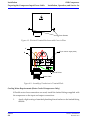
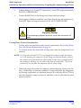
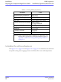
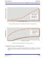
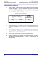
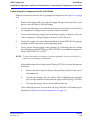
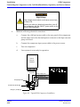
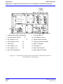
8200 Compressor Installation, Operation and Service Instructions 8040353 Revision AA 8200 Compressor Installation, Operation and Service Manual Information provided within this document is subject to change without notice, and although believed to be accurate, Brooks Automation assumes no responsibility for any errors, omissions, or inaccuracies. AcuLigner™, Align™, AquaTran™, AutoTeach™, ATR™, AXM™, Basic Blue™, BiSymmetrik™, CenterSmart™, Cool Solutions™, Crate to Operate™, e-RMA™, e-Spares™, e-Volution™, FastRegen™, FIXLOAD™, FrogLeg™, InLigner™, InCooler™, Interface™, Jet Engine™, LowProfile™, M2 Nano™, Mini-Ion™, PASIV™, PowerPak™, PerformanceBlue™, PowerPak™, PowerTools™, QuadraFly™, Radius™, Radient™, Radient Express™, Reliance™, Reliance ATR™, RetroEase™, SCARA™, SmartPM™, SPOTLevel™, Synetics™, The New Pathway to Productivity™, Time Optimized Trajectory™, Time Optimal Trajectory™, Time Optimized Path™, TopCooler™, TopLigner™, Ultimate Blue™, VAC-407™, VacuTran™, Vacuum Quality Monitor™, VQM™, Vacuum Quality Index™, VQI™, and the Brooks logo are trademarks of Brooks Automation, Inc. AcuTran®, AquaTrap®, Conductron®, Convectron®, the Cool Solutions logo, Cryodyne®, Cryotiger®, Cryo-Torr®, Fusion®, GOLDLink®, Granville-Phillips®, Guardian®, GUTS®, Helix®, Jet®, Leapfrog®, MagnaTran®, MapTrak®, Marathon®, Marathon 2®, Marathon Express®, Micro-Ion®, MiniConvectron®, On-Board®, Polycold®, Razor®, Simplicity Solutions®, the Simplicity Solutions logo, Stabil-Ion®, TrueBlue®, TurboPlus®, Vision®, Zaris®, and the Brooks Automation logo are registered U.S. trademarks of Brooks Automation, Inc. All other trademarks are properties of their respective owners. © 2013 Brooks Automation, Inc. All Rights Reserved. The information included in this manual is Proprietary Information of Brooks Automation and is provided for the use of Brooks Automation customers only and cannot be used for distribution, reproduction, or sale without the express written permission of Brooks Automation. This information may be incorporated into the user’s documentation, however any changes made by the user to this information is the responsibility of the user. For Technical Support: Location GUTS® Contact Number North America +1-800-FOR-GUTS (1-800-367-4887) +1-978-262-2900 Europe +49-1804-CALL-GUTS (+49-1804-2255-4887) Japan +81-45-477-5980 China +86-21-5131-7066 Taiwan +886-3-5525225 Korea +82-31-288-2500 Singapore +65-6464-1481 Visit us online: www.brooks.com January 11, 2013 Part Num 8040353 Revision AA This technology is subject to United States export Administration Regulations and authorized to the destination only; diversion contrary to U.S. law is prohibited. Printed in the U.S.A. Brooks Automation 8040353 Revision AA 8200 Compressor Installation, Operation, and Service Instructions Contents Contents Introduction General. . . . . . . . . . . . . . . . . . . . . . . . . . . . . . . . . . . . . . . . . . . . . . . . . . . . . . . . . . . . . . .1-2 Installation, Operation and Servicing Instructions . . . . . . . . . . . . . . . . . . . . . . . . . .1-3 Safety Introduction . . . . . . . . . . . . . . . . . . . . . . . . . . . . . . . . . . . . . . . . . . . . . . . . . . . . . . . . . .2-2 Signal Word Descriptions . . . . . . . . . . . . . . . . . . . . . . . . . . . . . . . . . . . . . . . . . . . . . . .2-3 Safety Shape Descriptions. . . . . . . . . . . . . . . . . . . . . . . . . . . . . . . . . . . . . . . . . . . . . . .2-4 References . . . . . . . . . . . . . . . . . . . . . . . . . . . . . . . . . . . . . . . . . . . . . . . . . . . . . . . . . . . .2-4 Inspection The Compressor . . . . . . . . . . . . . . . . . . . . . . . . . . . . . . . . . . . . . . . . . . . . . . . . . . . . . . .3-2 Installation Compressor Installation . . . . . . . . . . . . . . . . . . . . . . . . . . . . . . . . . . . . . . . . . . . . . . . .4-2 Preparing the Compressor Input-Power Cable . . . . . . . . . . . . . . . . . . . . . . . . . . . .4-2 Final Preparation of Compressor. . . . . . . . . . . . . . . . . . . . . . . . . . . . . . . . . . . . . . . . .4-8 Connecting the Compressor to the Cold Head . . . . . . . . . . . . . . . . . . . . . . . . . . . . .4-9 Maintenance Procedures Scheduled Maintenance . . . . . . . . . . . . . . . . . . . . . . . . . . . . . . . . . . . . . . . . . . . . . . . .5-2 Brooks Automation Revision AA 8040353 iii Contents 8200 Compressor Installation, Operation, and Service Instructions Unscheduled Maintenance . . . . . . . . . . . . . . . . . . . . . . . . . . . . . . . . . . . . . . . . . . . . . .5-6 Helium Circuit Decontamination . . . . . . . . . . . . . . . . . . . . . . . . . . . . . . . . . . . . . . . .5-9 Appendices Appendix A: Customer Brooks Automation Technical Support Information. . .6-2 Appendix B: Troubleshooting Procedures . . . . . . . . . . . . . . . . . . . . . . . . . . . . . . . . .6-3 Appendix C: Electrical Schematics for 8200 Compressor . . . . . . . . . . . . . . . . . . . .6-7 Appendix D: Components in the Electrical Control Module of the 8200 Compressor 6-10 Appendix E: Flow Diagrams for 8200 Air-Cooled and Water-Cooled Compressors612 Appendix F: Additional Cooling Water Quality Parameters . . . . . . . . . . . . . . . . .6-15 8040353 iv Brooks Automation Revision AA 8200 Compressor Installation, Operation, and Service Instructions Figures Figures 1-1 1-2 Air and Water Cooled 8200 Compressor Dimensions . . . . . . . . . . . . . . . . .1-3 Component Locations . . . . . . . . . . . . . . . . . . . . . . . . . . . . . . . . . . . . . . . . . . . .1-4 4-1 4-2 4-3 4-4 4-5 Electrical Terminal Enclosure with Cover in Place. . . . . . . . . . . . . . . . . . . .4-4 Assembly of Conductors to Terminal Block . . . . . . . . . . . . . . . . . . . . . . . . .4-4 8200 Compressor Cooling Water Flow and Pressure Requirements . . . . .4-7 8200 Compressor Water Cooling Requirements . . . . . . . . . . . . . . . . . . . . . .4-7 Typical 8200 Compressor Installation. . . . . . . . . . . . . . . . . . . . . . . . . . . . . . .4-10 5-1 5-2 5-3 Adjusting the Self-Sealing Connectors . . . . . . . . . . . . . . . . . . . . . . . . . . . . . .5-3 Disconnecting/Connecting the Adsorber Self-Sealing Coupling. . . . . . . .5-3 Removing the Adsorber from the Compressor . . . . . . . . . . . . . . . . . . . . . .5-4 6-1 6-2 6-3 8200 Compressor Electrical Schematic part number 8032563P001 . . . . . .6-8 8200 Compressor Electrical Schematic part number 8032564P001 . . . . . .6-9 Components in the Electrical Control Chassis of the 8200 Compressor Three-Phase Scott-T Configuration . . . . . . . . . . . . . . . . . . . . . . . . . . . . . . . . .6-10 Components in the Electrical Control Chassis of the 8200 Compressor Single-Phase RC Configuration . . . . . . . . . . . . . . . . . . . . . . . . . . . . . . . . . . . .6-11 Flow Diagram of the 8200 (Air-Cooled) Compressor . . . . . . . . . . . . . . . . .6-13 Flow Diagram of the 8200 (Water-Cooled) Compressor. . . . . . . . . . . . . . .6-14 6-4 6-5 6-6 Brooks Automation Revision AA 8040353 v Figures 8200 Compressor Installation, Operation, and Service Instructions This Page Intentionally Left Blank 8040353 vi Brooks Automation Revision AA 8200 Compressor Installation, Operation, and Service Instructions Tables Tables 1-1 1-2 Power Requirements (Steady-State Conditions) . . . . . . . . . . . . . . . . . . . . . .1-5 General Specifications . . . . . . . . . . . . . . . . . . . . . . . . . . . . . . . . . . . . . . . . . . . .1-5 2-1 2-2 Safety Signal Words. . . . . . . . . . . . . . . . . . . . . . . . . . . . . . . . . . . . . . . . . . . . . .2-3 Safety Shapes . . . . . . . . . . . . . . . . . . . . . . . . . . . . . . . . . . . . . . . . . . . . . . . . . . .2-4 4-1 Cooling Water Specifications . . . . . . . . . . . . . . . . . . . . . . . . . . . . . . . . . . . . . .4-6 6-1 6-2 Compressor Troubleshooting Procedures . . . . . . . . . . . . . . . . . . . . . . . . . . .6-3 Additional Cooling Water Quality Parameters . . . . . . . . . . . . . . . . . . . . . . .6-15 Brooks Automation Revision AA 8040353 vii Tables 8200 Compressor Installation, Operation, and Service Instructions This Page Intentionally Left Blank 8040353 viii Brooks Automation Revision AA 8200 Compressor Installation, Operation, and Service Instructions 1 Introduction Overview This chapter describes this manual and the compressor, including specifications. Chapter Contents General. . . . . . . . . . . . . . . . . . . . . . . . . . . . . . . . . . . . . . . . . . . . . . . . . . . . . . . . . . . . . . .1-2 Installation, Operation and Servicing Instructions . . . . . . . . . . . . . . . . . . . . . . . . . .1-3 Brooks Automation Revision AA 8040353 1-1 Introduction General 8200 Compressor Installation, Operation, and Service Instructions General The manual provides instructions for installing, operating and servicing the 8200 Compressor. This compressor is available in two versions: air-cooled, part number 8032549G001/G002 and water cooled, part number 803255G001/G002. If you are installing or operating a Cryo-Torr or On-Board System you should also have available the appropriate cryopump or refrigerator. When you purchase a system, you will receive two manuals necessary for system installation. 8040353 1-2 Brooks Automation Revision AA 8200 Compressor Introduction Installation, Operation, and Service InstructionsInstallation, Operation and Servicing In- Installation, Operation and Servicing Instructions Installation, Operation and Servicing Instructions for your 8200 Compressor provide easily accessible information. All personnel with installation, operation, and servicing responsibilities should become familiar with the contents of these instructions to ensure high quality, safe, reliable performance. Air Cooled Water Cooled Figure 1-1: Air and Water Cooled 8200 Compressor Dimensions Brooks Automation Revision AA 8040353 1-3 Introduction 8200 Compressor Installation, Operation and Servicing InstructionsInstallation, Operation, and Service In- 1 2 3 4 5 6 7 8 9 10 11 12 Rear View - Water Cooled Rear View - Air Cooled 13 14 15 16 17 18 Front View - Air and Water Cooled 1. Compressor Input Power Block LEGEND 10. Cooling Water Output 2. Cold Head Power Receptacle 11. Cooling Water Input 3. On-Board Power Receptacle 12. Rear Plate 4. Helium Gas Fitting and Charge Valve 13. 50/60 Hz Frequency Selector Switch 5. Helium Supply Pressure Gauge 14. 208/220 Voltage Range Selector Switch 6. Helium Gas Return Connector 15. Resettable Circuit Breakers Figure 1-2: Component Locations 8040353 1-4 Brooks Automation Revision AA 8200 Compressor Introduction Installation, Operation, and Service InstructionsInstallation, Operation and Servicing In- Table 1-1: Power Requirements (Steady-State Conditions) Part Number Cooling Phase Hz Operating Voltage Range Nominal Operating Current Rated Full Load / Locked Current 8032549G001 Air Air 3 3 50 60 180-220 198-250 10A 10A 12/30A 8032549G002 Air Air 1 1 50 60 180-220 198-250 10A 10A 12/30A 8032550G001 Water Water 3 3 50 60 180-220 198-250 8.5A 8.5A 12/30A 8032550G002 Water Water 1 1 50 60 180-220 198-250 8.5A 8.5A 12/30A *See the nameplate on the back of the compressor for more details. Table 1-2: General Specifications Specification Description Weight 150 lbs (68 kg) max. Weight (shipping) 155 lbs (70 kg) max. Power consumption Compressor inputpower cable (customer-supplied) Helium pressure Ambient operating temperature range Brooks Automation Revision AA 2.0 kw, nominal operating(water), 2.1 kw nominal operating (air) Recommended type SO-4 conductor, 600V, neoprene jacket and 14-gauge wire. Install per Appendix C: Electrical Schematics for 8200 Compressor on page 6-8, Electrical Schematic diagram, ensuring compliance with all national, state and local standards. Static: 245-255 psig (1688-1757 kPa) at 70 to 80°F (21 to 27°C) Supply: nominal operation: 270-290 psig (1860-2000 kPa) at operating temperature. 50 to 100°F (10 to 38°C) 8040353 1-5 Introduction 8200 Compressor Installation, Operation and Servicing InstructionsInstallation, Operation, and Service InTable 1-2: General Specifications (Continued) Specification Description Interface Cold head power receptacle: Mates with plug on cold head power cable. On-Board power receptacle: Mates with plug on coldhead power cable. Compressor input-power terminal block enclosure: Mates with input power cable, fabricated by customer or available from BROOKS-Cryogenics. Gas-supply connector: 1/2-inch self-sealing coupling Gas-return connector: 1/2-inch self-sealing coupling Adsorber service schedule Cooling water requirements (water cooled only) 8040353 1-6 Replace every 12 months. 100°F (38°C) maximum discharge temperature Refer to Table 1-1 on page 1-5, Figure 1-1 on page 1-3, and Figure 1-2 on page 1-4, for parameters. Brooks Automation Revision AA 8200 Compressor Installation, Operation, and Service Instructions 2 Safety Overview This section describes safety conventions for the Brooks Automation Product. All personnel involved in the operation or maintenance of the product must be familiar with the safety precautions outlined in this section. NOTE: These safety recommendations are basic guidelines. If the facility where the Product is installed has additional safety guidelines they should be followed as well, along with the applicable national and international safety codes. Chapter Contents Introduction . . . . . . . . . . . . . . . . . . . . . . . . . . . . . . . . . . . . . . . . . . . . . . . . . . . . . . . . . .2-2 Signal Word Descriptions . . . . . . . . . . . . . . . . . . . . . . . . . . . . . . . . . . . . . . . . . . . . . . .2-3 Safety Shape Descriptions. . . . . . . . . . . . . . . . . . . . . . . . . . . . . . . . . . . . . . . . . . . . . . .2-4 References . . . . . . . . . . . . . . . . . . . . . . . . . . . . . . . . . . . . . . . . . . . . . . . . . . . . . . . . . . . .2-4 Brooks Automation Revision AA 8040353 2-1 Safety Introduction 8200 Compressor Installation, Operation, and Service Instructions Introduction Follow all safety precautions during installation, normal operation, and when servicing BROOKS-Cryogenics products. This chapter explains the safety conventions used throughout this manual. BROOKS-Cryogenics uses a specific format for cautions and warnings, which includes standard signal words and safety shapes. See also the Customer Support appendix or call your local Customer Support Center for assistance. 8040353 2-2 Brooks Automation Revision AA 8200 Compressor Installation, Operation, and Service Instructions Safety Signal Word Descriptions Signal Word Descriptions All cautions and warnings contain signal words, which call attention to safety messages and designate the degree of hazard seriousness. The following table shows the signal words and their meanings that may be used in this document. Table 2-1: Safety Signal Words Term Example Definition CAUTION A signal word that indicates a situation or unsafe practice, which if not avoided may result in equipment damage. A CAUTION is highlighted in yellow. CAUTION A signal word accompanied by a safety shape that indicates a potentially hazardous situation or unsafe practice. If not avoided, the action may result in minor or moderate personal injury or equipment damage. A CAUTION is highlighted in yellow. WARNING A signal word accompanied by a safety shape that indicates indicates a potentially hazardous situation. If not avoided, the action may result in serious injury or death. A WARNING is highlighted in orange. Brooks Automation Revision AA 8040353 2-3 Safety Safety Shape Descriptions 8200 Compressor Installation, Operation, and Service Instructions Safety Shape Descriptions All cautions and warnings contain safety shapes, which have specific safety meanings. The following table shows some of the safety shapes used in this document and their meanings. Table 2-2: Safety Shapes Example Term Shape Definition General Warning Indicates a general hazard. Details about this hazard appear in the safety notice explanation. High Voltage Hot Surface Indicates a high voltage hazard. Indicates a surface is hot enough to cause discomfort or a burn. References For more information about safety standards, see the following documents: 8040353 2-4 • ISO 7010: 2003(E), Graphic symbols - Safety colours and safety signs - Safety signs used in workplaces and public areas • ISO 3864-1: 2002(E), Graphic symbols - Safety colours and safety signs - Part 1: Design principles for safety signs in workplaces and public areas Brooks Automation Revision AA 8200 Compressor Installation, Operation, and Service Instructions 3 Inspection Overview This chapter details unpacking the compressor. A High-Vacuum Pump or Refrigerator System is packaged in separate cartons for each major component. An Installation, Operation, and Servicing Manual is included in the carton for the component packaged in that carton. Chapter Contents The Compressor . . . . . . . . . . . . . . . . . . . . . . . . . . . . . . . . . . . . . . . . . . . . . . . . . . . . . . .3-2 Brooks Automation Revision AA 8040353 3-1 Inspection The Compressor 8200 Compressor Installation, Operation, and Service Instructions The Compressor On receipt, remove the 8200 Compressor from its shipping carton and inspect the compressor for evidence of damage as described in this Section. 1. Unpack and remove the compressor from its shipping carton. 2. Check the carton contents. It should contain: 3. a. 8200 Compressor (air cooled or water cooled). b. Compressor Manual part number 8040353. After unpacking, inspect the compressor for evidence of damage as follows: c. Inspect the compressor overall exterior for damage. d. Report damage to the shipper at once. e. Retain shipping cartons for storage or return shipment. When installing your system, BROOKS recommends that as you unpack a component, you perform an inspection and the necessary tasks for system installation for the component according to the manual included with the component. Final system installation and operation will be performed following procedures in the high-vacuum pump or refrigerator manual. 4. 8040353 3-2 Check the helium pressure gauge. The gauge should indicate 250 psig (1725 kPa) minimum at 70°F. If additional gas pressure is required, follow the instructions in Helium Circuit Decontamination on page 5-9. Brooks Automation Revision AA 8200 Compressor Installation, Operation, and Service Instructions 4 Installation Overview This chapter provides complete installation procedures for the Brooks Automation Product. Chapter Contents Compressor Installation . . . . . . . . . . . . . . . . . . . . . . . . . . . . . . . . . . . . . . . . . . . . . . . .4-2 Preparing the Compressor Input-Power Cable . . . . . . . . . . . . . . . . . . . . . . . . . . . . .4-2 Cooling Water Requirements (Water-Cooled Compressors Only) . . . . . .4-4 Cooling Water: General Considerations. . . . . . . . . . . . . . . . . . . . . . . . . . . . .4-5 Cooling Water: Flow and Pressure Requirements . . . . . . . . . . . . . . . . . . . .4-6 Cooling Water: Heat Load and Temperature Rise . . . . . . . . . . . . . . . . . . . .4-7 Final Preparation of Compressor. . . . . . . . . . . . . . . . . . . . . . . . . . . . . . . . . . . . . . . . .4-8 Connecting the Compressor to the Cold Head . . . . . . . . . . . . . . . . . . . . . . . . . . . . .4-9 Brooks Automation Revision AA 8040353 4-1 Installation Compressor Installation 8200 Compressor Installation, Operation, and Service Instructions Compressor Installation Installation of your compressor requires no special tools other than those supplied in the Installation and Scheduled Maintenance Tool Kit. Preparing the Compressor Input-Power Cable To supply input power to the 8200 compressor requires the fabrication of a 600-volt power cable that has an SO-4 conductor, 600-volt rating neoprene jacket and 14-gauge or 2.3 mm2 wire. Unit must be wired by an authorized electrician in accordance with the national Electrical Code, ANSI/NFPA 70-1987, as well as the local codes. This shall include installation of a readily accessible disconnect device into the fixed wiring supplying power. An insulated earthing conductor that is identical in size, insulation material and thickness to the earth and unearth branch circuit supply conductors, except that it is green with or without one or more yellow stripes is to be installed as part of the branch circuit which supplies the unit or system. The earthing conductor described is to be connected to the earth at the service equipment, or supplied by a separately derived system at the supply transformer or generator. Proceed as follows: High Voltage High voltage electric shock could cause severe injury or loss of life. Do not connect the compressor to the power source at this time. Complete the preparation and panel reinstallation before electrically connecting the compressor. 8040353 4-2 1. Prepare the input power cable by terminating each of the four conductors with a #10 ring terminal. Follow the terminal manufacturer’s instructions to insure proper crimping. 2. Disassemble the electrical terminal enclosure cover, mounted on the compressor rear panel, as shown in Figure 4-1 on page 4-4. Remove the two screws securing the cover and lift it off. 3. If necessary, back off strain relief screws. Brooks Automation Revision AA 8200 Compressor Installation Installation, Operation, and Service Instructions Preparing the Compressor Input-Power 4. Thread input power cable end up through the strain relief into the enclosure. 5. Attach the power conductors onto the appropriate terminals of the terminal block. a. For three-phase hookups, attach the three power leads to terminals X, Y and Z. b. For single-phase hookups, attach the two power leads to terminals X and Y. DO NOT USE TERMINAL Z. 6. Tighten all terminals to 18-22 in.-lbs. torque. 7. Tighten down screws on strain relief. Equipment Damage To avoid damaging the power cable, ensure that strain relief is tightened down on the outer insulation of the input power cable, and that the cable does not slide. 8. Remount the terminal enclosure cover and secure with two screws. 9. Refer to Final Preparation of Compressor on page 4-8 for correct phasing checkout procedure. High Voltage High voltage electric shock could cause severe injury or loss of life. Ensure that the ground wire is grounded and uninterrupted. Brooks Automation Revision AA 8040353 4-3 Installation Preparing the Compressor Input-Power Cable 8200 Compressor Installation, Operation, and Service In- Cover Screws Figure 4-1: Electrical Terminal Enclosure with Cover in Place Y Z (not used for single phase) X Ground Screw Power Cable Figure 4-2: Assembly of Conductors to Terminal Block Cooling Water Requirements (Water-Cooled Compressors Only) If flexible water hose connections are used, install the barbed fittings supplied with the compressor on the input and output connections: 1. 8040353 4-4 Apply a light coating of standard plumbing thread sealant on the barbed fitting threads. Brooks Automation Revision AA 8200 Compressor Installation Installation, Operation, and Service Instructions Preparing the Compressor Input-Power 2. Tighten fittings on 1/2-inch FPT input and 1/2-inch FPT output connections. DO NOT OVERTIGHTEN. 3. Connect flexible hoses to the fittings and secure with hose clamps. If hard piping is desired, install the water lines directly onto the compressor 1/ 2-inch FPT input and output connections. DO NOT OVERTIGHTEN. Equipment Damage To avoid damaging adjacent equipment, check water connections for leaks. Cooling Water: General Considerations • Cooling water must meet flow and pressure requirements. See Cooling Water: Flow and Pressure Requirements on page 4-6. • To conserve water, the shut off the cooling water when the compressor is not running. NOTE: If cooling water below 45°F (7°C) runs through the compressor while the compressor is not operating, the compressor oil will change viscosity and thicken, causing the compressorto overheat and shut off at startup. In this event, repeatedly restart the compressor, allowing it to run until it has shut off several times. The oil temperature will rise and then the compressor will run continuously. • Drain and purge water from the compressor before shipping it back to the factory or subjecting it to freezing conditions. Purge water from the compressor by blowing compressed air, regulated between 30 to 40 psig (200 to 275 kPa) into the compressor output connection, and allow water to exit from the water input connection. Brooks Automation Revision AA 8040353 4-5 Installation Preparing the Compressor Input-Power Cable 8200 Compressor Installation, Operation, and Service In- Table 4-1: Cooling Water Specifications Parameter Value Maximum Inlet Temperature 90º F (32º C) Minimum Inlet Temperature 50º F (10º C) Flow Rate 1.0 ± 0.5 gpm (3.8 ± 1.9 lpm) Pressure Drop (inlet-to-outlet) approximately 3.5 psig differential Min. / max. Inlet Presure 5 to 100 psi (6.9 bars) Alkalinity 7.0 - 8.7 pH Calcium Carbonate < 75 ppm Resistivity < 100 k Ohm - cm NOTE: Water conditioning may be required for applications not meeting these requirements. Additional parameters appear in Appendix F: Additional Cooling Water Quality Parameters on page 6-16. Cooling Water: Flow and Pressure Requirements Use Figure 4-1 on page 4-4 and Figure 4-4 on page 4-7 to determine the minimum acceptable cooling water supply pressure at different flow rates and temperatures 8040353 4-6 Brooks Automation Revision AA 8200 Compressor Installation Installation, Operation, and Service Instructions Preparing the Compressor Input-Power MinimumRequiredwater Pressure(PSIG) 60 50 40 30 Allowable Operating Range 20 at m in. water flowrate 10 0 0.25 0.50 0.75 1.00 1.50 1.75 2.00 Water Flowrate (GPM) Figure 4-3: 8200 Compressor Cooling Water Flow and Pressure Requirements 90 85 W ater SupplyTem perature(ºF) 80 Allowa b le Op era ting Ra nge 75 70 65 60 55 50 45 40 0.25 0.50 0.75 1.00 1.50 1.75 2.00 Water Flowrate (GPM) Figure 4-4: 8200 Compressor Water Cooling Requirements Cooling Water: Heat Load and Temperature Rise Heat load to facility water is approximately 5000 Btu/hr, or 1500 Watts. With a 1.0 GPM water flow this translates to an approximate water temperature rise of 10ºF (5.6ºC) Brooks Automation Revision AA 8040353 4-7 Installation Final Preparation of Compressor 8200 Compressor Installation, Operation, and Service Instructions Final Preparation of Compressor 1. Using a voltmeter, measure the phase-to-phase voltage from the power source. Compare this voltage to Table 4-1 and position the voltage range selector switch to the “208V” or “220V” position as required. Also, set the frequency selector switch to the 50 Hz or 60 Hz position, as appropriate. See Figure 1-2 on page 1-4 for location of selector switches. Table 4-1: Voltage Specifications Operating Voltage Range 60 Hz 50 Hz 8040353 4-8 Voltage Adjustment Switch S1 Position 198-212 180-212 208V 213-250 213-220 220V 2. Ensure that water is turned on for the water-cooled compressor. 3. Set the compressor ON/OFF switch (3) to OFF. Connect the input-power cable to the power source Refer to Table 1-1 on page 1-5, for electrical power requirements. 4. Turn the compressor switch to the ON position and allow the compressor to run for 15 minutes to stabilize the oil circuit. Make sure that the compressor fan operates freely in the air-cooled compressor. 5. Switch off the compressor and disconnect the input-power cable. 6. Install the compressor in its permanent location on a level surface. Air cooled units must have a minimum clearance of 12 inches at the front and back for adequate airflow. Brooks Automation Revision AA 8200 Compressor Installation Installation, Operation, and Service Instructions Connecting the Compressor to the Cold Connecting the Compressor to the Cold Head Make the connections between the cryopump and compressor. See Figure 4-5 on page 4-10. 1. Remove dust plugs and caps from the supply fittings and return lines, compressor, and cold head. Check all fittings. 2. Connect the helium-gas return line from the gas-return connector on the rear of the compressor to the gas-return connector on the cold head. 3. Connect the helium-gas supply line from the gas-supply connector on the rear of the compressor to the gas-supply connector on the cold head. 4. Attach the supply and return line identification decals (BROOKS-Cryogenics supplied) to their respective connecting piping ends. 5. Verify proper helium supply static pressure by confirming that the helium pressure gauge reads 245-250 psig (1690-1725 kPa), in an ambient temperature range of 60 to 100°F (16 to 38°C). NOTE: To ensure the compressor continues to perform optimally, do not run it unless it is connected to a cryopump or waterpump. If the indicated pressure is higher than 250 psig (1725 kPa), reduce the pressure as follows: a. Remove the flare cap from the gas charge fitting located on the rear of the compressor. b. Open the gas charge valve very slowly. Allow a slight amount of helium gas to escape until the helium pressure gauge reads 250 psig (1725 kPa). c. Close the gas charge valve and reinstall the flare cap. If the indicated pressure is lower than 245 psig (1690 kPa), add helium gas as described in Helium Circuit Decontamination on page 5-9. Brooks Automation Revision AA 8040353 4-9 Installation 8200 Compressor Connecting the Compressor to the Cold HeadInstallation, Operation, and Service Instruc- High Voltage High voltage electric shock could cause severe injury or loss of life. Before you make any electrical connections, turn off the compressor with the ON/OFF power switch on the front of the compressor. 6. Make the following electrical connections. a. Connect the cold head power cable to the rear panel of the compressor and the other end to the electrical power connector on the high-vacuum pump cold head. b. Connect the compressor input power cable to the power source. c. Turn on compressor. d. Your system is now ready for operation. User’s Vacuum Chamber On-Board Cryopump Helium Supply Line Helium Return Line On-Board Power Cable Roughing Pump Air Pressure (60-80 psi) Nitrogen (40-80 psi) Figure 4-5: Typical 8200 Compressor Installation 8040353 4-10 Brooks Automation Revision AA 8200 Compressor Installation, Operation, and Service Instructions 5 Maintenance Procedures Overview This chapter provides complete maintenance procedures for the Brooks Automation Product. Chapter Contents Scheduled Maintenance . . . . . . . . . . . . . . . . . . . . . . . . . . . . . . . . . . . . . . . . . . . . . . . .5-2 Unscheduled Maintenance . . . . . . . . . . . . . . . . . . . . . . . . . . . . . . . . . . . . . . . . . . . . . .5-6 Helium Circuit Decontamination . . . . . . . . . . . . . . . . . . . . . . . . . . . . . . . . . . . . . . . .5-9 Brooks Automation Revision AA 8040353 5-1 Maintenance Procedures Scheduled Maintenance 8200 Compressor Installation, Operation, and Service Instructions Scheduled Maintenance The only scheduled maintenance required on the 8200 Compressor is replacement of the compressor adsorber (part number 8080255K001) every 12 months. High Voltage High voltage electric shock could cause severe injury or loss of life. Always disconnect the compressor from all sources of electrical power before performing any maintenance procedures. Removing the Compressor Adsorber 8040353 5-2 1. Shut down the compressor. 2. Disconnect the compressor input power cable from its electrical power source. 3. Disconnect the flex lines from the gas-return and gas-supply connectors at the rear of the compressor. 4. Remove the screws holding the compressor rear grille, rear panel, front panel and cover (Figure 1-2 on page 1-4). Front and rear panels remain in place. 5. Use the two wrenches (supplied) to avoid loosening the body of the coupling from its adapter. 6. Unscrew the two self-sealing coupling halves quickly to minimize gas leakage as shown in Figure 5-2 on page 5-3. 7. Disconnect the adsorber-inlet self-sealing coupling as shown in Figure 5-2 on page 5-3. 8. Remove the bolts, nuts, and washers that secure the adsorber to the base of the compressor. Save all nuts, bolts, and washers for installing the replacement adsorber. 9. Carefully lift the adsorber inward until the outlet self-sealing coupling clears the rear panel and remove the adsorber as shown in Figure 5-3 on page 5-4. 10. Remove the adsorber from the compressor as shown in Figure 5-2 on page 5-3. Brooks Automation Revision AA 8200 Compressor Installation, Operation, and Service Instructions Maintenance Procedures Scheduled Maintenance TO TIGHTEN TURN WITH 1 3/16 INCH WRENCH HOLD WITH 1 1/8 INCH WRENCH HOLD WITH 1 1/8 INCH WRENCH TURN WITH 1 3/16 INCH WRENCH TO LOOSEN Figure 5-1: Adjusting the Self-Sealing Connectors Compressor Rear Panel This 1 1/8 in. wrench holds the coupling in a stationary position. This 1 3/16 in. wrench is used to loosen the self sealing coupling connector. Note the direction of the large arrow. To Disconnect The Coupling This 1 1/8 in. wrench holds the coupling in a stationary position. This 1 3/16 in. wrench is used to tighten the self sealing coupling connector. Note the direction of the large arrow. To Connect The Coupling Figure 5-2: Disconnecting/Connecting the Adsorber Self-Sealing Coupling Brooks Automation Revision AA 8040353 5-3 Maintenance Procedures Scheduled Maintenance 8200 Compressor Installation, Operation, and Service Instructions Explosive Pressure High pressure explosions could cause severe injury and equipment damage. Appropriately depressurize the adsorber before disposing of it. To depressurize the adsorber, attach the depressurization fitting (included in the Installation and Scheduled Maintenance Tool Kit) to the coupling half at either end of the adsorber and tighten it slowly. Compressor Base Figure 5-3: Removing the Adsorber from the Compressor Installing the Compressor Adsorber 1. 2. 8040353 5-4 Install the replacement adsorber as follows: a. Remove the dust caps from the self-sealing coupling halves at each end of the replacement adsorber. b. Write installation date on the adsorber decal. c. Install the replacement adsorber following the steps for compressor adsorber removal in reverse order. Use the hardware saved in Step 5 on Page 5-2. Connect the adsorber to the compressor internal piping. Refer to Figure 5-2 on page 5-3. Brooks Automation Revision AA 8200 Compressor Installation, Operation, and Service Instructions a. Maintenance Procedures Scheduled Maintenance Check the self-sealing connector flat rubber gasket to make sure that it is clean and properly positioned. Equipment Damage To avoid damaging equipment, ensure you hold the left coupling nut while tightening the right coupling nut, as shown in Figure 5-2 on page 53 and Figure 5-1 on page 5-3. b. Make the first turns by hand and then firmly seal the connection using the two wrenches until the fittings “bottom.” Refer to Figure 5-2 on page 5-3 and Figure 5-1 on page 5-3, for proper coupling of the self-sealing connection 3. Replace the cover and the front and rear grilles and secure them 4. Ensure that the pressure gauge reads 245-250 psig (1690-1725 kPa). If additional gas pressure is required, follow the instructions in Adding Helium Gas on page 5-6. 5. Reconnect the return and supply flex lines to the compressor. 6. Connect the compressor input power cable to the electrical power source. Brooks Automation Revision AA 8040353 5-5 Maintenance Procedures Unscheduled Maintenance 8200 Compressor Installation, Operation, and Service Instructions Unscheduled Maintenance Suggested Unscheduled Maintenance Equipment It is advisable to keep on hand the unscheduled maintenance equipment and disposable supplies listed below. 1. Helium, 99.999% pure. 2. Pressure regulator (0-3000/0-400 psig). 3. Maintenance manifold, part number 8080250K003*. 4. Helium charging line terminating in a 1/4-inch female flare fitting, part number 7021002P001. 5. Installation and Scheduled Maintenance Tool Kit, part number 8032040G004. *Available from stock; consult the factory or your sales representative. Adding Helium Gas Use only 99.999% pure helium gas. Equipment Damage To avoid damaging the cold head and other parts through contamination, maintain pressure in the cold head. If the compressor helium pressure gauge reads 0, decontamination is required. Refer to the Helium Circuit Decontamination on page 5-9, or contact the Product Service Department. 8040353 5-6 1. A user-supplied helium charging line terminating in a 1/4-inch female flare fitting, and a two-stage pressure regulator rated at 0-3000/0-400 psig is required for this operation. 2. If you need to add helium more than once every several months, check for leaks caused by improperly connected self-sealing connections or any mechanical joint within the compressor. Brooks Automation Revision AA 8200 Compressor Installation, Operation, and Service Instructions Maintenance Procedures Unscheduled Maintenance There are two conditions that require the addition of helium gas: 1. Compressor not operating; helium pressure gauge reads 245 psig or below. 2. Compressor operating; helium pressure reads 270 psig, or below. To add helium gas: 1. Attach a pressure regulator (0-3000/0-400 psig) and charging line to a helium gas (99.999% pure) bottle. DO NOT OPEN THE BOTTLE AT THIS TIME. Purge the regulator and charging lines as instructed in steps a through e below. Do not use helium gas that is less than 99.999% pure. a. Open the regulator a small amount by turning the adjusting knob clockwise until it contacts the diaphragm, then turn approximately 1/8 to 1/4 turn more, so that the regulator is barely open. b. Slowly open the bottle valve, and purge the regulator for 10 to 15 seconds. Turn the regulator knob counterclockwise until the helium stops flowing. c. Connect the charge line to the helium pressure regulator. d. Remove the flare cap of the gas charge fitting on the rear of the compressor. Loosely connect the charge line to the charge fitting. e. Set the helium pressure regulator to 10 to 25 psig (70-125 kPa). Allow helium gas to flow through the charging line and around the loosened flare fitting for 30 seconds to purge the charging line of air. Then tighten the flare nut at the end of the charge line. (This procedure is required to ensure that both the regulator and the charging line will be purged of air and that the air trapped in the regulator will not diffuse back into the helium bottle. For best results, BROOKS suggests a dedicated helium bottle, regulator, and line, which are never separated, for adding helium.) 2. Set the helium pressure regulator to 300 psig (2070 kPa). Depending on the compressor operating state, add helium gas: a. Brooks Automation Revision AA If the compressor is running (approximately 2 hours operating time) under normal operating conditions, slowly open the helium charge valve on the rear of the compressor. When the helium pressure gauge rises to 270 - 290 psig (1860 - 2000 kPa) tightly close the charge valve. 8040353 5-7 Maintenance Procedures Unscheduled Maintenance b. 8200 Compressor Installation, Operation, and Service Instructions If the compressor is not running, slowly open the helium charge valve. When the helium pressure gauge rises to 245 - 255 psig (1688 - 1757 kPa), tightly close the charge valve. Equipment Damage To avoid discharging the relief valve, add helium gas slowly, less than 50 psi per second. 3. 8040353 5-8 Ensure that the helium charge valve on the compressor is tightly closed. Shut off the helium pressure regulator on the helium bottle and remove the charging line from the male flare fitting. Shut off the helium gas bottle valve. Reinstall the flare cap. Brooks Automation Revision AA 8200 Compressor Installation, Operation, and Service Instructions Maintenance Procedures Helium Circuit Decontamination Helium Circuit Decontamination Refer to Section 4 - Maintenance of the appropriate On-Board Cryopump Installation Operation, and Maintenance manual for information on helium circuit decontamination. Brooks Automation Revision AA 8040353 5-9 Maintenance Procedures Helium Circuit Decontamination 8200 Compressor Installation, Operation, and Service Instructions This Page Intentionally Left Blank 8040353 5-10 Brooks Automation Revision AA 8200 Compressor Installation, Operation, and Service Instructions 6 Appendices Overview The following appendices are included to provide the user with a single location for specific information related to the Brooks Automation Product. Contents Appendix A: Customer Brooks Automation Technical Support Information . . .6-3 Appendix B: Troubleshooting Procedures . . . . . . . . . . . . . . . . . . . . . . . . . . . . . . . . .6-4 Appendix C: Electrical Schematics for 8200 Compressor . . . . . . . . . . . . . . . . . . . .6-8 Appendix D: Components in the Electrical Control Module of the 8200 Compressor 6-11 Appendix E: Flow Diagrams for 8200 Air-Cooled and Water-Cooled Compressors613 Appendix F: Additional Cooling Water Quality Parameters . . . . . . . . . . . . . . . . .6-16 Brooks Automation Revision AA 8040353 6-1 Appendices 8040353 6-2 8200 Compressor Installation, Operation, and Service Instructions Brooks Automation Revision AA 8200 Compressor Appendices Installation, Operation, and Service Instructions Appendix A: Customer Brooks Automa- Appendix A: Customer Brooks Automation Technical Support Information When contacting Brooks Automation for Technical Support, please have the following information available. 1. Record the part number and serial number from the equipment. 2. Provide the installed location of the equipment. 3. Provide name, e-mail address, and telephone number of the person to contact. 4. List any error codes received during the failure. 5. Prepare a detailed description of the events relating to the error. 6. • Time that the equipment has been in operation • Work that was done on the equipment prior to the error • Functions that the equipment was performing when the error occurred • Actions taken after the error and the results of those actions • Other information that may assist the Specialist Contact Brooks Automation Technical Support at these numbers: Brooks Location North America Europe Japan China Taiwan Korea Singapore GUTS® Contact Number 1-800-FOR-GUTS (1-800-367-4887) US/Canada +1-978-262-2900 +49 1804 CALL GUTS (+49 1804 2255 4887) +81-45-477-5980 +86-21-5131-7066 +886-3-552-5225 +82-31-288-2500 +65-6464-1481 For additional contact information, please go to the Brooks Automation web site at www.brooks.com or send an E-mail to [email protected]. Brooks Automation Revision AA 8040353 6-3 Appendices Appendix B: Troubleshooting Procedures 8200 Compressor Installation, Operation, and Service Instruc- Appendix B: Troubleshooting Procedures Read these safety notices before you perform any troubleshooting procedures: High Voltage High voltage electric shock could cause severe injury or loss of life. Always disconnect the compressor from all sources of electrical power before performing any maintenance or troubleshooting procedures. Burn Hazard To avoid being burned, wait for the pump to cool down so that it is cool to the touch after operating, before working on the inside of the compressor. Table 6-1: Compressor Troubleshooting Procedures Problem 1) System power ON/ OFF switch (CB1) and compressor switch (S1) remains in the ON position when switched on but the compressor will not run. Refer to Figure 6-1 on page 6-9 for identification of all electrical components. 8040353 6-4 Possible Cause Corrective Action 1a) The thermal protective switch (TS1) is closed, activating the relay-trip coil in the ON/OFF switch (SW1). 1a) Test switch (TS1) on aircooled compressor; test (TS1) and (TS2) on water-cooled compressor. If continuity is found in any switch, contact the Product Service Department. 1b) Incorrect phasing at input power. 1b) Correct phase sequence at input power cable. 1c) Excessive current drain has activated the series trip in the compressor ON/OFF switch. 1c) Measure and record the current and contact the Product Service Department. Brooks Automation Revision AA 8200 Compressor Installation, Operation, and Service Instructions Appendices Appendix B: Troubleshooting Proce- Table 6-1: Compressor Troubleshooting Procedures Problem 2) System power ON/ OFF switch (CB1) remains in the ON position, but the compressor will not run. Brooks Automation Revision AA Possible Cause Corrective Action 2a) No power coming from the power source. 2a) Check service fuses, circuit breakers, and wiring associated with power source, and repair as needed. 2b) Incorrect or disconnected wiring within the compressor. 2b) Check the compressor against its electrical schematic, Figure 6-1 on page 6-9. 8040353 6-5 Appendices Appendix B: Troubleshooting Procedures 8200 Compressor Installation, Operation, and Service Instruc- Table 6-1: Compressor Troubleshooting Procedures Problem 3) Compressor stops after several minutes of operation and remains off. 8040353 6-6 Possible Cause Corrective Action 3a) High temperature of the compressor is caused by insufficient cooling water, resulting in the opening of thermal protective switch (water-cooled compressor only). 3a) Confirm that cooling water to the compressor is flowing. Confirm that proper cooling water flow rate and pressure exist by referring to Figure 4-3 on page 4-7. 3b) After turn-off, very cold cooling water was left running through the compressor. The resulting low oil temperature has caused a restriction of oil flow through the metering orifice during startup. 3b) Turn on the compressor and allow it to run until it has stopped several times, allowing the oil temperature to rise and the compressor to operate continuously for one hour minimum. 3c) Very cold cooling water is circulating through the compressor. The resulting low oil temperature causes a restriction of oil flow through the metering orifice during startup. 3c) Recheck for proper cooling water temperature per, Cooling Water Requirements (Water-Cooled Compressors Only). 3d) Ambient temperature is unusually high resulting in the opening of the thermal protective switch (air-cooled compressor only). 3d) Provide a free flow of air to the compressor. Confirm a 12inch (30 cm) clearance at the front and back of the compressor. Confirm unobstructed and clean heat exchanger surfaces. 3e) Insufficient helium supply pressure is indicated by the supply pressure gauge. 3e) Add helium per, Unscheduled Maintenance on page 5-6. 3f) High temperature of the compressed helium in the discharge line from the compressor pump has tripped the thermal protective switch. 3f) Confirm that oil is visible in the compressor sight glass (aircompressor only). 3g) Mechanical seizure. 3g) Contact the Product Service Department. Brooks Automation Revision AA 8200 Compressor Installation, Operation, and Service Instructions Appendices Appendix B: Troubleshooting Proce- Table 6-1: Compressor Troubleshooting Procedures Problem Possible Cause Corrective Action 4) Compressor pump 4a) Intermittent power source stops after several voltage. minutes of operating and then switches ON and OFF at short intervals. 4a) Confirm power source voltage between 198-250V, 60 Hz or 180-220V, 50 Hz and restore if necessary. 5) Compressor operates but cold head motor does not run. 5a) Loose or defective cable. 5a) Check cold head cable. 6a) The water coming into the compressor is too warm. 6a) Ensure the water coming into the compressor is between 50°F (32º C) and 90°F (10º C). 6b) The water is becoming too warm within the compressor due to a problem with the compressor. 6b) Contact the Product Service Department. 6) Cooling water leaving the compressor exceeds 100°F. Brooks Automation Revision AA 8040353 6-7 Appendices 8200 Compressor Appendix C: Electrical Schematics for 8200 Compressor Installation, Operation, and Ser- Appendix C: Electrical Schematics for 8200 Compressor The following electrical schematics for the 8200 Compressor are in this appendix: 8040353 6-8 • 8200 Compressor Electrical Schematic part number 8032563P001 • 8200 Compressor Electrical Schematic part number 8032564P001 Brooks Automation Revision AA MAIN CIRCUIT BREAKER CIRCUIT BREAKER, 3A CIRCUIT BREAKER, 3A MOTOR START RELAY METER ELAPSED TIME COLDHEAD CONNECTOR PUMP CONNECTOR THERMOSTAT CONNECTOR SOLENOID CONNECTOR FAN CONNECTOR TRANSFORMER CONNECTOR TRANSFORMER CONNECTOR TRANSFORMER CONNECTOR TRANSFORMER CONNECTOR OVERTEMPERATURE TRIP RELAY VOLTAGE SELECTOR RELAY PUMP MOTOR FAN MOTOR, AIR COOLED ONLY PHASE MONITOR ON-BOARD CONNECTOR CRYO-TORR CONNECTOR OVERTEMPERATURE RESISTOR BLEED RESISTOR CURRENT LIMITER VOLTAGE SELECTOR SWITCH FREQUENCY SELECTOR SWITCH SOLENOID TRANSFORMER TRANSFORMER TERMINAL BLOCK, INCOMING VOLTAGE THERMOSTAT THERMOSTAT, FOR WATER COOLED USE TS1 AND TS2 CB1 CB2 CB3 CR1 ETM J1 J2 J3 J4 J5 J/P6 J/P7 J/P8 J/P9 K1 K2 M1 M2 PM J10 J11 R1 R2 RT1 S1 S2 SOL1 T1 T2 TB1 TS1 TS2 119UF START CAPACITOR, C2 35UF RUN CAPACITOR, C1 TB1 1 Brooks Automation Revision AA 9 11 12 GND WHT/BLU WHT/ORN WHT/YEL ORN FREQUENCY WHT/BLK/BLU 60 Hz BRN WHT/BRN WHT/ORN WHT/GRA WHT/BLU 0 220V 208V 220V 198 - 212 213 - 250 S1 213 - 220 0 T2 20 0 20 0 WHT ORN 60 Hz 60 Hz 50 Hz 50 Hz S2 BLK GRA WHT WHT/VIO WHT/YEL ORN BLK 138 - 162 148 - 159 121 - 125 118 - 139 CH VOLTS 2 2 1 1 5 5 4 3 3 6 6 2a 2b WHT/BLK/VIO WHT YEL J/P8 7 7 1 1 2 2 5 5 4 4 3 3 6 J/P7 7 7 WHT/RED WHT BLK GRA WHT W/VIO W/YEL WHT/RED t 0 212 162 t 12 24 t 0 212 162 t 12 24 208V 250 217 188 125 108 250 217 188 125 108 T1 K1 180 - 212 LINE VOLTS 1 1 BLU J/P9 6 5 5 4 4 3 2 2 2 WHT/BLU 1 1 BLU 3 3 WHT/GRA J/P6 6 6 BRN 5 5 WHT/BRN 4 WHT/ORN C NO W/BLK 50 Hz VIO BRN WHT/BRN R1 NC WHT/BLK GRN/YEL-14 POWER IN BLK 14 WHT/RED RED 14 K2 5 1 7 3 8 4 WHT WHT/RED 1. VOLTAGE SELECTION: 13 14 10 BLU NOTES: 1A 15A CB3 3A 3 P3 2 P2 L3 Z WHT t RT1 CB2 3A 15A P1 L2 Y WHT/ORN 60 HZ 50 HZ ETM 2 R 20.5 - 24.0 21.9 - 23.5 20.5 - 21.2 19.9 - 23.5 1b 220V 2a 208V 2b 1a C1 S PM NO C NC A C T R2 119UF CONTROL VOLTS YEL BRN WHT/BRN S2 1 C2 S1 B 1 2 35UF 1 2 BLK RED CR1 WHT YEL 5 WHT/VIO BLK RED WHT/RED W/BRN BRN WHT/BLK/VIO GRA YEL BRN-14 YEL W/ORN Figure 6-1: 8200 Compressor Electrical Schematic part number 8032563P001 CB1 L1 x 208/230 VAC 3ph J3 J2 J1 J4 J5 3 4 30 4 0 40 10 3 4 34 10 1 2 3 4 5 6 7 8 9 33 P1 33 1 2 3 4 5 6 7 8 9 11 22 1 1 22 P4 11 22 P3 2 4 24 11 2 2 1 4 14 P2 1 0 14 P5 TS1 J10 VIOGRA ORN F E D C B 0 4 4 4 4 J11 A 4 A B C D E F G H J K M1 PUMP WATER COOLED ONLY TS2 GRN/YEL 14 CRYO-TORR ON-BOARD CONNECTOR SOL1 C BLK 14 RED 14 S R BRN 14 FAN M2 AIR COOLED ONLY 8200 Compressor Installation, Operation, and Service Instructions Appendices Appendix C: Electrical Schematics for YEL GRN/YEL 8040353 6-9 Figure 6-2: 8200 Compressor Electrical Schematic part number 8032564P001 Appendices 8200 Compressor Appendix C: Electrical Schematics for 8200 Compressor Installation, Operation, and Ser- 8040353 6-10 Brooks Automation Revision AA 8200 Compressor Appendices Installation, Operation, and Service Instructions Appendix D: Components in the Electri- Appendix D: Components in the Electrical Control Module of the 8200 Compressor The following illustrations are shown in this chapter: • Components in the Electrical Control Chassis of the 8200 Compressor Three-Phase Scott-T Configuration (this page) • Components in the Electrical Control Chassis of the 8200 Compressor Single-Phase RC Configuration 1. Overtemperature ResistorR1 9. Circuit Breaker, 3ACB3 2. Run Capacitor, 35 µfC1 10. Voltage Selector SwitchS1 3. Start Capacitor, 119 µfC2 11. Frequency Selector SwitchS2 4. TransformerT2 12. Overtemperature Trip RelayK1 5. Phase MonitorPM 13. TransformerT1 6. Voltage Selector RelayK2 14. Motor Start RelayCR1 7. Main Circuit BreakerCB1 15. Meter, Elapsed TimeETM 8. Circuit Breaker, 3ACB2 Figure 6-3: Components in the Electrical Control Chassis of the 8200 Compressor Three-Phase Scott-T Configuration Brooks Automation Revision AA 8040353 6-11 Appendices 8200 Compressor Appendix D: Components in the Electrical Control Module of the 8200 Compressor 1. Coldhead Phase-Shifting ResistorR3 9. Circuit Breaker, 3ACB2 2. Overtemperature Resistor 10. Circuit Breaker, 3ACB3 R1 3. Run Capacitor, 35 µf C1 11. Voltage Selector SwitchS1 4. Start Capacitor, 119 µf C2 12. Frequency Selector SwitchS2 5. Transformer T2 13. Relay, Trip RelayK1 6. Run Capacitor, 2 µf C4 14. TransformerT1 7. Run Capacitor, 6 µf C3 15. Motor Start RelayCR1 8. Main Circuit BreakerCB1 16. Meter, Elapsed TimeETM Figure 6-4: Components in the Electrical Control Chassis of the 8200 Compressor Single-Phase RC Configuration 8040353 6-12 Brooks Automation Revision AA 8200 Compressor Installation, Operation, and Service Instructions Appendices Appendix E: Flow Diagrams for 8200 Appendix E: Flow Diagrams for 8200 Air-Cooled and Water-Cooled Compressors Refer to Figure 6-5 on page 6-14 or Figure 6-6 on page 6-15 while reviewing this subsection. Helium returning from the cold head enters the compressor, and a small quantity of oil is injected into the gas stream, thereby overcoming helium low specific head and inability to carry heat produced during compression. Helium is then compressed and passed through a heat exchanger for removal of compression-caused heat. The helium flows through a bulk oil separator, oil-mist separator, and helium filter cartridge, where oil and contaminants are removed. A differential pressure relief valve in the compressor limits the operating pressure differential between the helium supply and return lines, thereby allowing compressor operating without cold head operation. When cold head operation reaches a steadystate condition, further pressure regulation is unnecessary. Brooks Automation Revision AA 8040353 6-13 Appendices 8200 Compressor Appendix E: Flow Diagrams for 8200 Air-Cooled and Water-Cooled CompressorsInstalla- Figure 6-5: Flow Diagram of the 8200 (Air-Cooled) Compressor 8040353 6-14 Brooks Automation Revision AA 8200 Compressor Installation, Operation, and Service Instructions Appendices Appendix E: Flow Diagrams for 8200 Figure 6-6: Flow Diagram of the 8200 (Water-Cooled) Compressor Brooks Automation Revision AA 8040353 6-15 Appendices Appendix F: Additional Cooling Water Quality Parameters 8200 Compressor Installation, Operation, and Appendix F: Additional Cooling Water Quality Parameters Table 6-2: Additional Cooling Water Quality Parameters Water Constituent Unit Saturation-Index SI (delta pH-value) 8040353 6-16 Acceptable Limits -0.2 < 0 < +0.2 Total hardness °dH 6 - 15 Conductivity mg/l 10...500 Filtered substances mg/l <30 Chlorides mg/l <500 Free chlorine mg/l <0.5 Hydrogen sulphide mg/l <0.05 Ammonia mg/l <2 Sulphates mg/l <100 Hydrogen carbonate mg/l <300 Hydrogen carbonate / sulphates mg/l >1.0 Sulphide mg/l <1 Nitrate mg/l <100 Nitrite mg/l <0.1 Iron mg/l <0.2 Manganese mg/l <0.1 Free agressive carbonic acid mg/l <20 Brooks Automation Revision AA