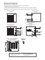
1
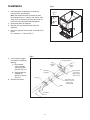
Follett Maestro™ Chewblet® 400 Series
Ice Machine and Top Kit
for Remcor/Cornelius Countertop ice and beverage dispensers
Order parts online
www.follettice.com
Installation, Operation and Service Manual
4
20826
ation
Identific
Module
Stock No.
Module
ProductNo.
Service
Plate
ia
sylvan
n Penn NO
Easto PART
E
SINGLE
PHAS
OZ
HZ
ION L NO
ECTED
ORATSERIA
PSIG
GE
S
Y PROT
CORP
IN
VOLT MALL CHAR
SIDE
USA
MADE
EL
THE
R THER
LOW
NSF
RESSO
AMPS
RUL
R COMP
LOAD
C
MOTO
RU L
SIDE
NT
AMPS
HIGH
CITY
GERA
URE
AMPS
REFRI
IT AMPA SIZE
N PRESS CIRCU FUSE
IT
CH
DESIG
BRAN CH CIRCU
MIN. BRAN
MAX.
MOD
FULL
Following installation, please forward this manual
to the appropriate operations person.
801 Church Lane • Easton, PA 18040, USA
Toll free (877) 612-5086 • +1 (610) 252-7301
www.follettice.com
00117259R05
Table of contents
Welcome to Follett Corporation
3
Important cautions
3
Specifications
4
Installation
6
Operation
14
Cleaning
14
Replacement Parts
16
Models MTC22SC, MSC22SC
16
Models MTC24SC, MSC24SC
17
Models MTC30SC, MSC30SC
18
Model MSC44SC
19
2
Welcome to Follett
Follett equipment enjoys a well-deserved reputation for excellent performance, long-term reliability and
outstanding after-the-sale support. To ensure that this equipment delivers that same degree of service, we
ask that you review the installation portion of this manual before beginning to install the unit. Our installation
instructions are designed to help you achieve a trouble-free installation. Should you have any questions or
require technical help at any point, please call our technical service group at (877) 612-5086 or (610) 252-7301.
Before you begin
After uncrating and removing all packing material, inspect the equipment for concealed shipping damage. If
damage is found, notify the shipper immediately and contact Follett Corporation so that we can help in the filing
of a claim, if necessary.
Check your paperwork to determine which model you have. Follett model numbers are designed to provide
information about the type and capacity of Follett equipment. Following is an explanation of the different model
numbers in the series.
MSC22SC
Ice machine configuration
SC = self-contained
Dispenser size
22 = 22" wide
24 = 24" wide
30 = 30" wide
44 = 44" wide
Dispenser manufacturer
C = Cornelius
L = Lancer
S = SerVend
Ice machine mounting
MT = Maestro top mount
MS = Maestro RIDE model
!
Important cautions
Dispenser bin area contains mechanical, moving parts. Keep hands and arms clear of this
area at all times. If access to this area is required, power to unit must be disconnected first.
Follett recommends a Follett water filter system (part# 00130229 for the 400 series) be
installed in the ice machine inlet water line.
Ice is slippery. Maintain counters and floors around dispenser in a clean and ice-free condition.
Ice is food. Follow recommended cleaning instructions to maintain cleanliness of delivered ice.
3
Specifications
Electrical
Model number
MC400 series ice machine
Full load amps
115/60/1
Max. fuse size
11.0 amps
20 amps
Ambient specifications
Air temperature
+100 F/+38 C max.
+50 F/+10 C min. (best performance below +80 F/+27 C)
Water temperature
+90 F/+32 C max.
+40 F/+4 C min. (best performance below +70 F/+21 C)
Water pressure
70 P.S.I. max.(482kPA) 10 P.S.I min. (89kPA)
Plumbing
Your new ice machine is equipped with a drain line to simplify draining the evaporator and float reservoir. The tube
labeled “float/evap drain” is for SERVICE USE ONLY and must NOT be connected to the ice machine drain.
Water line sizes
Drain line sizes
Slope to drain
Make up water (inlet to float)
1/4" min.
Condenser (water-cooled only)
3/8" min.
Ice machine drain
3/4" min.
Condenser (water-cooled only)
3/8" min.
1/4" per foot (6mm per 30.4cm run)
1/2" min.
•
Water shut-off recommended within 10 feet (3m), drain to be hard-piped and insulated
•
Separate drains for ice machine and condenser. To prevent back flow, do NOT connect drains.
•
Follett recommends installation of a Follett water filter system (part# 00130229) in ice machine inlet water line
Field Wiring: countertop dispensers with RIDE™ remote ice delivery model
ice machines
Consult enclosed D400A/W, R400A/W, MCD400A/W manual.
4
Dimensions and clearances
Required clearances – MCD400 series
Entire front of ice machine clear of obstruction/connections to allow removal.
12" (305mm) above ice machine for service
6" (153mm) minimum between louvered (exhaust) side of ice machine and any adjacent equipment.
MCD400AHS – 18" (457mm) minimum, 10 ft (3m) maximum between discharge and air intake grilles.
Front view — air-cooled
top mount
Back view — air-cooled
top mount
13.00"
(331mm)
C
4.875"
(124mm)
2.375"
(61mm)
B
Front view — water-cooled
RIDE model
Back view — water-cooled
top mount
Front view — air-cooled
RIDE model
C
12.875"
(327mm)
F
8.375"
(213mm)
B
A
4.75"
(121mm)
2.25"
(57mm)
1.875" (48mm)
Side view — air-cooled and water-cooled
top mount and RIDE model
A
C
F
B
E
1.875" (48mm)
7.00" (178mm)
Ice machine plug
configuration
NEMA 5-20
22.75" (578mm)
20.75" (527mm)
17.00"
(432mm)
RIDE model air-cooled units only
A – 3/4" MPT drain
B – 3/8" OD push-in water inlet
C – Electrical cord
D – 3/8" FPT condenser inlet
E – 3/8" FPT condenser drain
F – Bin signal cord
5
6.875"
(175mm)
D
A
2"
(51mm)
Installation
1.
Fig. 1
Install Cornelius ice dispenser according to
manufacturer’s specifications.
agitation
timer
Note: We recommend that the dispenser back
be mounted at least 1" (26mm) from wall to allow
water, drain and electric lines from top-mount ice
machines to be concealed behind dispenser.
ON
OFF
2. Disconnect power to dispenser.
3. Remove front panel/merchandiser from the
dispenser.
4. Adjust the agitation timer located on Cornelius PC
board
to 1 second on – 1 hour off (Fig. 1).
Fig. 2
5. Install supplied nugget
ice diverter at dispenser
opening.
storage hopper
a) Disassemble
chute assembly
and discard gate
restrictor (Fig. 2.1).
b) Reassemble with
supplied ice
diverter as shown
(Fig. 2.2).
1
gate
mounting
plate
2
gate
restrictor
plate
ice diverter
(supplied)
flange extends
into storage
hopper through
gate opening
ice chute
6. Reinstall front panel.
apply RTV to this
surface to seal to
hopper gate
mounting plate
gasket
flat washer
10-32 nut
6
7.
Fig. 3
Remove existing plastic top from dispenser
and install supplied gasket around perimeter of
dispenser top (Fig. 3).
gasket
Note: Sanitize dispenser before proceeding.
Fig. 4
8. Install supplied stainless steel top with access
opening toward front of dispenser (Fig. 4).
For dispensers with top mounted ice machines
Proceed with steps 9 through 17.
For dispensers with RIDE model ice machines
Go directly to step 18.
7
Fig. 5
Top mounted ice machine installation
9. Position Follett MCD400AHT ice machine on
perimeter gasket of stainless steel top. Ice machine
should be oriented with A/C condenser facing front
(Fig 5).
4
20826
tion
Identifica
Module
Stock No.
Module
ProductNo.
Service
Plate
MAX.
8
a
ylvani
PennsNO
Easton PART
HZ
ION L NO
CTED
ORATSERIA
PROTE GE
CORP
VOLTS ALLY CHAR
SIDE
LOW
L
R THERM
MODE
RESSO
AMPS
R COMP
LOAD
MOTO
FULL
SIDE
NT
AMPS
HIGH
CITY
GERA
URE
AMPS
REFRI
IT AMPA SIZE
N PRESS CIRCU FUSE
IT
CH
DESIG
BRAN CH CIRCU
MIN. BRAN
RU L
RUL
C
E
SINGLE
PHAS
OZ
PSIG
NSF
IN
USA
MADE
THE
Fig. 6
10. Use pliers to compress and remove cage nut at
front of condenser on ice machine base (Fig. 6.1).
11. Install filter and grille. Lock in place using four
mounting screws (Fig. 6.2).
AIR
OUT
IN
AIR
2
2
208264
tion
Plate
Identifica
lvania
Module
Stock No.
Module
Product No.
Pennsy NO
Easton PART
Service
N
VOLTS ALLY
THERM
FULL
ESSOR
AMPS
COMPR
LOAD
MOTOR
SIDE
AMPS
ERANT HIGH
URE
REFRIG
N PRESS
SINGLE
PHASE
OZ
HZ
NO
RATIO
SERIAL
CORPO
CTED
E
PROTE
CHARG
SIDE
LOW
MODEL
PSIG
IN
MADE
USA
THE
NSF
UL
R
UL
C
R
AMPS
AMPACITY
DESIG
1
CIRCUIT
BRANCH
MIN.
SIZE
FUSE
CIRCUIT
BRANCH
MAX.
filter
grille
12. Make water, drain and electric connections to ice
machine (Fig. 7).
Fig. 7
Note: Water connection accepts 3/8" OD copper
or plastic tubing. Push tubing in until it stops.
Use supplied 90˚ push-in water inlet fitting
if there is not enough clearance behind ice
machine to install water tubing without kinking
tubing or putting stress on fitting.
Note: Follett recommends the installation of a Follett
water filter system (par# 00130229) on supply
water inlet.
Back view – air-cooled
top mount
Power
115V
C
3/8" OD
water inlet
Drain
3/4" MPT
9
B
A
Fig. 8
13. Remove ice machine top panel and louvered side
panel.
14. Insert ice transport tube to a 1/2" (13mm) depth
through mounting bracket (Fig 8 and 9.1) and
secure transport tube away from condenser fan
under float reservoir bracket
(Fig. 9.2).
ice transport tube
15. Tighten clamp screw(s) on ice machine base
securely (Fig. 9.3).
16. Uncoil capillary tube from bin thermostat and route
through hole in gasket to mounting bracket and
secure as shown (Fig. 8).
1/2"
bin thermostat
capillary tube
17. Reinstall ice machine louvered side panel and top
panel.
2"
GO TO STARTUP – STEP 27.
Fig. 9
2
insert ice
transport
tube
1
3
10
tighten
clamp
screw
3" (77mm)
18. Ice transport tube chase may be located behind
or to either side of the dispenser (Fig. 10 and
11). Using the chase mounting bracket (Fig.
12) as a template mark the counter for the ice
transport tube(s) in one of the locations shown
in Fig. 10 and 11. Within the template outline
drill one 2.25" (58mm) to 2.375" (61mm) hole
for each ice transport tube. Secure the chase
mounting bracket to the counter using supplied
screws (Fig. 12).
rear entry chase
A
B
1.25" (32mm)
3" (77mm)
Fig. 10 – Single ice tube dispensers
RIDE model ice machine installation
side entry
chase
1.25
(32mm)
2.25" (57mm) 2.375" (61mm) 1.25"
(32mm)
dia. hole
typical
side entry
chase
6"
(153mm)
front
22" (559mm) dispenser
11.00" (280mm)
8.00" (242mm)
24" (607mm) dispenser
12.00" (312mm)
9.00" (299mm)
30" (762mm) dispenser
15.00" (762mm)
12.00" (343mm)
Single tube – Fig. 10
Fig. 11 – Double ice tube dispensers
rear entry chase
A
B
1.25" (32mm)
1.50" (38mm)
4.50" (115mm)
Dimension B
4.50" (115mm)
1.50" (38mm)
Dimension A
9.50" (242mm)
8.00" (204mm)
24" (607mm) dispenser
10.50" (273mm)
9.00" (242mm)
30" (762mm) dispenser
13.50" (343mm) 12.00" (305mm)
44" (1118mm) dispenser
20.50" (521mm) 19.00" (483mm)
1.25
(32mm)
side entry
chase
22" (559mm) dispenser
2.25" (57mm) 2.375" (61mm) 1.25"
(32mm)
dia. hole
typical
front
Fig. 12
11
side entry
chase
6"
(153mm)
Double tube – Fig. 11
19. Remove lid from dispenser top (Fig. 13.). Remove
the knockout from the Harmony top (Fig. 13.2)
corresponding to selected chase location. Line
the edges of the opening with the supplied gasket
material (Fig. 13.2).
Fig. 13
20. Follow the “RIDE model ice machine installation
procedure” found in the Symphony MCD400 Ice
machine Manual 208600 to install your Follett ice
machine.
1
1
2
2
1
2
21. Route the bin signal cord from the 4" x 4" (102mm x
102mm) junction box through the top knockout (Fig.
13.1) and countertop hole. Attach the bin signal
connector to the two lead plug on the ice machine.
22. Route the ice transport tube(s) from the ice
machine(s) through counter cutout and knock out
into dispenser top by following the same routing as
the bin signal cord (Fig. 13.2).
12
Fig. 14
23. Connect the ice transport tube(s) to the dispenser:
a) Drill 3/16" (5mm) holes through both sides of
the tube 1/2" (13mm) from the tube end.
b) Collapse tube and insert through gasketed hole
(Fig. 14.1).
c) Match tube holes to bracket tabs.
24. Route bin thermostat capillary tube from the 4" x 4"
(102mm x 102mm) junction box into bin alongside
the ice transport tube. Secure capillary tube into
bracket (Fig. 8).
25. Reinstall the dispenser cover with supplied screws
(Fig. 14).
1
26. Install telescoping chase.
a) Mount lower chase section to chase bracket on
counter with supplied screws (Fig. 15.1).
b) Position upper chase section over lower
chase section. Align top of upper section to
top of stainless dispenser top and secure with
screw (Fig. 15.2).
Fig. 15
c) Drill pilot holes on both sides of chase and
secure with supplied screws (Fig. 15.3).
27. Turn ice machine power and water on.
28. After ice machine has made ice for approximately
15 minutes complete the following start-up checks:
2
a) Dispense ice.
b) Hold ice on bin thermostat and make sure
ice machine shuts off.
c) Remove ice from bin thermostat and make sure
ice machine restarts.
Note: Ice machine has a 20 minute restart delay.
3
1
13
Operation
Weekly exterior evaporator unit care
The exterior may be cleaned with a stainless cleaner such as 3M Stainless Steel Cleaner & Polish or equivalent.
Recommended semi-annual ice machine/evaporator unit cleaning (every 6 months)
Fig. 16
Solution A – Sanitizing solution: Prepare 2 gallons (9L)
Combine 1 oz (250ml) bleach with 2 gal (8L) hot water or
equivalent 5.25% sodium hypochlorite solution.
Solution B – Ice machine cleaner: Prepare one gallon (3.8L)
of Follett SafeCLEAN™ Ice Machine Cleaner (one 7 oz packet) or
equivalent. Solution temperature must be at least +120 F
(+48.9 C).
2
1
3
Warning: Most ice machine cleaners contain citric or phosphoric
acid that can cause skin irritation. Read caution label on product
and follow instructions carefully.
Fig. 17
1.
Remove ice machine panels required to gain access to water
reservoir components (Fig. 16) and electrical control box.
2. Locate ice machine electrical box and turn compressor switch
off.
1
3. Dispense all ice from dispenser.
4. Shut off water to ice machine.
5. Drain water from reservoir through float/evaporator drain line
(Fig. 16.3). Reinsert hose into hose clip (Fig. 16.1).
3
6. Fill reservoir (Fig. 16.2) with Solution B.
7.
Restart ice machine and allow gearmotor to run with the
compressor off for 15 minutes.
4
8. While waiting 15 minutes, follow steps 8a through 8c.
a) Remove ice compression nozzles (Fig. 17.1). Soak in
Solution B.
b) Descale drain pans (Fig. 17.2) by grasping firmly and
gently bending up and down. Vacuum residue out.
c) Inspect all drain lines. Clean as necessary with Solution B.
9. Turn ice machine power off.
10. Drain Solution B through float/evaporator drain line
(Fig. 16.3). Rinse evaporator by filling reservoir (Fig. 16.2) with
potable water and draining evaporator through float/evaporator
drain line (Fig. 16.3) three times. Reinsert hose into hose clip
and plug into end of drain line (Fig. 16.1).
11. Connect ice transport tubes (Fig. 17.3) directly to evaporator
outlet ports (without ice compression nozzle) (Fig. 17.4).
12. Fill reservoir (Fig. 16.2) with Solution A.
13. Turn ice machine power on (to allow gearmotor to run).
14. Wait 10 minutes. Turn compressor switch on.
15. Keep reservoir (Fig. 16.2) full of Solution A while making ice for
20 minutes.
16. Turn compressor switch off.
14
2
17. Rinse ice compression nozzles (Fig. 17.1) with
water and reinstall.
18. Drain any remaining sanitizing solution from
reservoir through float/evaporator drain line (Fig.
16.1).
19. Fill reservoir (Fig. 16.2) with +120 F (+49 C) water.
Empty water through float/evaporator drain line
(Fig. 16.1). Repeat 3 times.
20. Turn on water to ice machine.
21. Turn compressor switch on.
22. Replace reservoir cover and any panels removed to
clean ice machine.
23. Make ice for 30 minutes. Dispense and discard all
ice.
15
Service
Replacement parts
Top kit models MTC22SC, MSC22SC
3
208264
tion
Identifica
Plate
vania
Module
Stock No.
Module
ProductNo.
Service
PennsylNO
Easton PART
OZ
NO
PSIG
TED
VOLTS PROTEC CHARGE
SIDE
LLY
LOW
THERMA
UL
ESSOR
AMPS
COMPR
LOAD
UL
MOTOR
FULL
SINGLE
PHASE
HZ
ATION
SERIAL
CORPOR
MODEL
HIGH
IN
MADE
USA
THE
10
NSF
R
C
R
SIDE
RANT
RE
REFRIGE
PRESSU
AMPS
AMPS
AMPACITY
DESIGN
CIRCUIT
SIZE
FUSE
BRANCH
MIN.
CIRCUIT
BRANCH
MAX.
14
13
15
2
4
12
12
9
1
11
8
5
6
Reference #
1
1
2
3
4
5
6
8
9
10
11
12
13
14
15
Not shown
Not shown
Not shown
Description
Part #
Base, top mount
Base, RIDE model
Cabinet
Cover
Chase, upper
Chase, lower
Collar
Deflector, single
Lid, access
Box, thermostat
Gasket, top, Harmony
Gasket, ice entry
Socket, bin signal
Kit, ice entry, MCD400
Plate, ice tube mounting, MCD400
Thermostat, bin level
Diverter, ice
Plate, blank, ice entry
00113506
00113266
00113324
00113357
00113381
00113399
00113407
501616
00113423
00113449
00113464
502824
502334
00120279
307071
500514
307277
00113498
16
Top kit models MTC24SC, MSC24SC
3
208264
tion
Identifica
Plate
vania
Module
Stock No.
Module
ProductNo.
Service
PennsylNO
Easton PART
OZ
NO
PSIG
TED
VOLTS PROTEC CHARGE
SIDE
LLY
LOW
THERMA
UL
ESSOR
AMPS
COMPR
LOAD
UL
MOTOR
FULL
SINGLE
PHASE
HZ
ATION
SERIAL
CORPOR
MODEL
HIGH
IN
MADE
USA
THE
10
NSF
R
C
R
SIDE
RANT
RE
REFRIGE
PRESSU
AMPS
AMPS
AMPACITY
DESIGN
CIRCUIT
SIZE
FUSE
BRANCH
MIN.
CIRCUIT
BRANCH
MAX.
14
13
15
2
4
12
12
9
1
11
8
5
6
Reference #
1
1
2
3
4
5
6
8
9
10
11
12
13
14
15
Not shown
Not shown
Not shown
Description
Part #
Base, top mount
Base, RIDE model
Cabinet
Cover
Chase, upper
Chase, lower
Collar
Deflector, single
Lid, access
Box, thermostat
Gasket, top, Harmony
Gasket, ice entry
Socket, bin signal
Kit, ice entry, MCD400
Plate, ice tube mounting, MCD400
Thermostat, bin level
Diverter, ice
Plate, blank, ice entry
00119495
00119487
00119503
00119511
00113381
00113399
00113407
501616
00113423
00113449
00113464
502824
502334
00120279
307071
500514
307277
00113498
17
Top kit models MTC30SC, MSC30SC
Top Kit models MRC44SC, MRC44RC
3
208264
tion
Identifica
Plate
lvania
Module
Stock No.
Module
ProductNo.
Service
Pennsy NO
Easton PART
SINGLE
PHASE
OZ
HZ
NO
RATION
SERIAL
ALLY
THERM
UL
ESSOR
AMPS
COMPR
LOAD
UL
MOTOR
FULL
SIDE
ERANT
HIGH
RE
REFRIG
PRESSU
PSIG
E
TED
VOLTS PROTEC CHARG
SIDE
LOW
CORPO
MODEL
IN
MADE
USA
THE
NSF
R
C
R
AMPS
AMPS
AMPACITY
DESIGN
CIRCUIT
SIZE
FUSE
BRANCH
MIN.
CIRCUIT
BRANCH
MAX.
10
14
13
15
4
2
1
9
12
9
12
1
11
8
8
12
5
6
Reference #
1
1
2
3
4
5
6
8
9
10
11
12
13
14
15
Not shown
Not shown
Not shown
Description
Base, top mount
Base, RIDE model
Cabinet
Cover
Chase, upper
Chase, lower
Collar
Deflector, single
Lid, access
Box, thermostat
Gasket, top, Harmony
Gasket, ice entry
Socket, bin signal
Kit, ice entry, MCD400
Plate, ice tube mounting, MCD400
Thermostat, bin level
Diverter, ice
Plate, blank, ice entry
Part #
18
00113282
00113274
00113332
00113365
00113381
00113399
00113407
501616
00113423
00113449
00113464
502824
502334
00120279
307071
500514
307277
00113498
Top Kit models MSC44SC
3
4
10
13
2
12
9
1
8
11
5
6
Reference #
1
2
3
4
5
6
8
9
10
11
12
13
Not shown
Not shown
Not shown
Description
Base, RIDE model
Cabinet
Cover
Chase, upper
Chase, lower
Collar
Deflector, single
Lid, access
Box, thermostat
Gasket, top, Harmony
Gasket, ice entry
Socket, bin signal
Thermostat, bin level
Diverter, ice
Plate, blank, ice entry
Part #
00113290
00113340
00113373
00113381
00113399
00113407
501616
00113423
00113449
00113464
502824
502334
500514
307277
00113498
19
Harmony, Maestro, SafeCLEAN and RIDE are trademarks of Follett Corporation.
Chewblet and Follett are registered trademarks of Follett Corporation, registered in the US.
801 Church Lane • Easton, PA 18040, USA
Toll free (877) 612-5086 • +1 (610) 252-7301
www.follettice.com
00117259R05
3/12