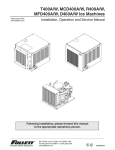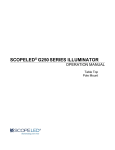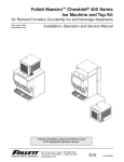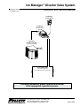
1
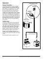
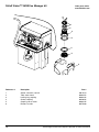
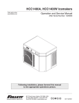
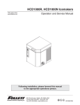
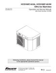
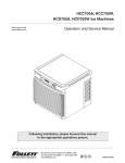
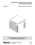
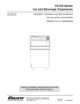
Ice Manager™ Diverter Valve System
Order parts online
www.follettice.com
Operation and Service Manual
Ice Manager
Control Panel
Ice Manager
Diverter Valve
(1) Horizon™
Chewblet® Icemaker
(purchased separately)
(purchased separately)
Any combination of bins or dispensers
Lane 2
Lane 1
(2) ice storage units
Following installation, please forward this manual
to the appropriate operations person.
801 Church lane • Easton, PA 18040, USA
Toll free (800) 523-9361 • (610) 252-7301
Fax (610) 250-0696 • www.follettice.com
00175273R00
Horizon™ 1000 & 1400 Series Icemaker Model Number Configurations
for use with Ice Manager Diverter Valve System
HC
Icemaker
Voltage
HC Horizon
C 208-230/60/1
(self-contained only)
Chewblet®
D Low side 115/60/1
Condensing unit
208-230/60/1
(remote condensing only)
E 230/50/1
C
1000
Series
1000 up to
1036 lbs
(471kg)
1400 up to
1450 lbs
(658kg)
A
M
S
Condenser
A
W
R
N
Air-cooled, self-contained
Water-cooled, self-contained
Air-cooled, remote condensing unit
Air-cooled, no condensing unit for
connection to parallel rack system
Application
Configuration
M Ice Manager† S Satellite-fill™
diverter valve
system
(self-contained only)
† Ice Manager Diverter Valve Systems can be used to fill any two of these bins or dispensers with a single ice machine.
Chewblet is a registered trademark of Follett Corporation, registered in the US.
Follett Corporation
Equipment Return Policy
Follett equipment may be returned for credit under the following conditions:
1. The equipment is new and unused.
2. A return authorization number has been issued by customer service within 30 days after shipment.
3. Follett receives the equipment at the factory in Easton, PA within 30 days after issuance of the return authorization number.
4. The equipment must be returned in Follett packaging. If the packaging has been damaged or discarded, Follett will forward, at the customer’s expense,
new packaging.
Note:
Return freight charges are the responsibility of the customer. If equipment is returned and is damaged because of improper packaging, Follett
Corporation will not be held responsible.
Credit will be issued when:
The equipment has been inspected by Follett and deemed suitable to be returned to stock.
Note:
2
A 15% restocking charge will be deducted from the credit. If the cost to return the product to stock exceeds 15%, the actual cost will be deducted.
Ice Manager Diverter Valve System Operation and Service Manual
Table of contents
Welcome to Follett
Before you begin. . . . . . . . . . . . . . . . . . . . . . . . . . . . . . . . . . . . . . . . . . . . . . . . . . . . . . . . . . . 4
Specifications
Electrical. . . . . . . . . . . . . . . . . . . . . . . . . . . . . . . . . . . . . . . . . . . . . . . . . . . . . . . . . . . . . . . . . 5
Plumbing. . . . . . . . . . . . . . . . . . . . . . . . . . . . . . . . . . . . . . . . . . . . . . . . . . . . . . . . . . . . . . . . . 5
Temperature requirements . . . . . . . . . . . . . . . . . . . . . . . . . . . . . . . . . . . . . . . . . . . . . . . . . . . 5
Dimensions. . . . . . . . . . . . . . . . . . . . . . . . . . . . . . . . . . . . . . . . . . . . . . . . . . . . . . . . . . . . . . . 5
Operation
General information. . . . . . . . . . . . . . . . . . . . . . . . . . . . . . . . . . . . . . . . . . . . . . . . . . . . . . . . . 6
Audible alarm . . . . . . . . . . . . . . . . . . . . . . . . . . . . . . . . . . . . . . . . . . . . . . . . . . . . . . . . . . . . . 6
Cleaning and preventive maintenance . . . . . . . . . . . . . . . . . . . . . . . . . . . . . . . . . . . . . . . . . . 7
Preventive maintenance . . . . . . . . . . . . . . . . . . . . . . . . . . . . . . . . . . . . . . . . . . . . . . . . . . . 7
Weekly exterior care. . . . . . . . . . . . . . . . . . . . . . . . . . . . . . . . . . . . . . . . . . . . . . . . . . . . . . 7
Cleaning and sanitizing. . . . . . . . . . . . . . . . . . . . . . . . . . . . . . . . . . . . . . . . . . . . . . . . . . . . 7
Service
System components. . . . . . . . . . . . . . . . . . . . . . . . . . . . . . . . . . . . . . . . . . . . . . . . . . . . . . . 20
System operation . . . . . . . . . . . . . . . . . . . . . . . . . . . . . . . . . . . . . . . . . . . . . . . . . . . . . . . . . 20
Control logic . . . . . . . . . . . . . . . . . . . . . . . . . . . . . . . . . . . . . . . . . . . . . . . . . . . . . . . . . . . 20
Auto mode. . . . . . . . . . . . . . . . . . . . . . . . . . . . . . . . . . . . . . . . . . . . . . . . . . . . . . . . . . . . . 20
Manual mode . . . . . . . . . . . . . . . . . . . . . . . . . . . . . . . . . . . . . . . . . . . . . . . . . . . . . . . . . . 20
Diverter valve module. . . . . . . . . . . . . . . . . . . . . . . . . . . . . . . . . . . . . . . . . . . . . . . . . . . . . . 21
Control board . . . . . . . . . . . . . . . . . . . . . . . . . . . . . . . . . . . . . . . . . . . . . . . . . . . . . . . . . . 21
Divert gearmotor. . . . . . . . . . . . . . . . . . . . . . . . . . . . . . . . . . . . . . . . . . . . . . . . . . . . . . . . 21
Divert paddle. . . . . . . . . . . . . . . . . . . . . . . . . . . . . . . . . . . . . . . . . . . . . . . . . . . . . . . . . . . 21
Ice Manager diverter valve wiring diagram. . . . . . . . . . . . . . . . . . . . . . . . . . . . . . . . . . . . 22
Control panel. . . . . . . . . . . . . . . . . . . . . . . . . . . . . . . . . . . . . . . . . . . . . . . . . . . . . . . . . . . . . 23
Membrane switch. . . . . . . . . . . . . . . . . . . . . . . . . . . . . . . . . . . . . . . . . . . . . . . . . . . . . . . 23
LCD screen. . . . . . . . . . . . . . . . . . . . . . . . . . . . . . . . . . . . . . . . . . . . . . . . . . . . . . . . . . . . 23
Audible alarm . . . . . . . . . . . . . . . . . . . . . . . . . . . . . . . . . . . . . . . . . . . . . . . . . . . . . . . . . . 23
Auger rotation switch. . . . . . . . . . . . . . . . . . . . . . . . . . . . . . . . . . . . . . . . . . . . . . . . . . . . . . . 24
Ultrasonic sensor . . . . . . . . . . . . . . . . . . . . . . . . . . . . . . . . . . . . . . . . . . . . . . . . . . . . . . . . . 24
Ice level set points. . . . . . . . . . . . . . . . . . . . . . . . . . . . . . . . . . . . . . . . . . . . . . . . . . . . . . . . . 25
To view ice levels . . . . . . . . . . . . . . . . . . . . . . . . . . . . . . . . . . . . . . . . . . . . . . . . . . . . . . . 25
To view set points. . . . . . . . . . . . . . . . . . . . . . . . . . . . . . . . . . . . . . . . . . . . . . . . . . . . . . . 25
To change set points for 23" or 30" drop-ins. . . . . . . . . . . . . . . . . . . . . . . . . . . . . . . . . . . 25
Troubleshooting
Ice shortage with audible alarm . . . . . . . . . . . . . . . . . . . . . . . . . . . . . . . . . . . . . . . . . . . . 26
Ice shortage without audible alarm. . . . . . . . . . . . . . . . . . . . . . . . . . . . . . . . . . . . . . . . . . 27
Service Parts
Diverter valve module. . . . . . . . . . . . . . . . . . . . . . . . . . . . . . . . . . . . . . . . . . . . . . . . . . . . . . 28
Control panel. . . . . . . . . . . . . . . . . . . . . . . . . . . . . . . . . . . . . . . . . . . . . . . . . . . . . . . . . . . . . 29
Sensor distribution unit. . . . . . . . . . . . . . . . . . . . . . . . . . . . . . . . . . . . . . . . . . . . . . . . . . . . . 30
Auger rotation switch. . . . . . . . . . . . . . . . . . . . . . . . . . . . . . . . . . . . . . . . . . . . . . . . . . . . . . . 31
Drop-in Ice Manager application kit. . . . . . . . . . . . . . . . . . . . . . . . . . . . . . . . . . . . . . . . . . . . 32
Follett Vision™ VU155 Ice Manager kit. . . . . . . . . . . . . . . . . . . . . . . . . . . . . . . . . . . . . . . . . 33
Follett Vision™ VU300 Ice Manager kit. . . . . . . . . . . . . . . . . . . . . . . . . . . . . . . . . . . . . . . . . 34
Cables. . . . . . . . . . . . . . . . . . . . . . . . . . . . . . . . . . . . . . . . . . . . . . . . . . . . . . . . . . . . . . . . . . 35
Ice Manager Diverter Valve System Operation and Service Manual
3
Welcome to Follett
Follett equipment enjoys a well-deserved reputation for excellent performance, long-term reliability and
outstanding after-the-sale support. To ensure that this equipment delivers the same degree of service, we ask
that you review the installation manual (provided as a separate document) before beginning to install the unit.
Our instructions are designed to help you achieve a trouble-free installation. Should you have any questions or
require technical help at any time, please call our technical service group at (800) 523-9361 or (610) 252-7301.
Before you begin
After uncrating and removing all packing material, inspect the equipment for concealed shipping damage. If
damage is found, notify the shipper immediately and contact Follett Corporation so that we can help in the filing
of a claim, if necessary.
CAUTION
• Warranty does not cover exterior or outside installations.
• Moving parts. Do not operate with front cover removed.
• Hot parts. Do not operate with cover removed.
• To reduce risk of shock, disconnect power before servicing.
• Most icemaker cleaners contain citric or phosphoric acid, which can cause skin irritation. Read caution label
on product and follow instructions carefully.
• Ice is slippery. Maintain counters and floors around dispenser in a clean and ice-free condition.
• Ice is food. Follow recommended cleaning instructions to maintain cleanliness of delivered ice.
4
Ice Manager Diverter Valve System Operation and Service Manual
Specifications
Electrical
115V, 60Hz, 1ph, 1.5 amps.
8' (2.4m) cord with NEMA 5-15 plug provided. If local code requires hard-wiring, separate disconnects also required.
Plumbing
Drain line – 15' (4.6m) 3/8" nylon tubing, supplied
Temperature requirements
Ice Manager components, including ice transport tube, must be operated in ambient temperatures between +40F and
+120F (+5C and +49C). Relative humidity not to exceed 55%.
Dimensions
Diverter Valve with Mounting Bracket
Front View
Control Panel
Side View
LANE 2
Front View
Side View
12"
(305mm)
13.625"
(346mm)
17.5"
(445mm)
3.75"
(96mm)
LANE 1
10.375"
(264mm)
12.5"
(318mm)
3/8" NPT
barbed drain fitting
16"
(407mm)
Sensor Distribution Unit
(bins and ice and beverage dispensers only)
Front View
Side View
3.5"
(89mm)
4.125"
(105mm)
7.75"
(197mm)
Ice Manager Diverter Valve System Operation and Service Manual
5
Operation
ICE MANAGER SYSTEM
General information
The Ice Manger diverter valve system is designed
to direct ice from one Horizon icemaker to two ice
storage units. AUTO is the standard operating mode.
When selected, ice is directed to the lane 1 storage
unit until it reaches the MIN (minimum) set-point.
Ice is then directed to the lane 2 storage unit and
will continue to fill this lane until the FULL level is
achieved. If at any time the ice level in lane 1 storage
unit goes below the MIN set-point, ice will be directed
back to lane 1 until the MIN level is satisfied. When
lane 2 reaches its FULL level, ice will be directed back
to lane 1. When both lanes reach their FULL level, the
Horizon icemaker will shut off. After a 15-minute delay,
the icemaker will be ready to start as soon as the ice
level in either of the storage units drops below the
FULL set-point.
Ice Manager
Control Panel
Ice Manager
Diverter Valve
(1) Horizon™
Chewblet® Icemaker
(purchased separately)
Audible alarm
In the event a system error occurs that could cause
ice shortages, the audible alarm will be turned ON
accompanied by an appropriate error message on the
LED screen. To silence the alarm, press any of the
push buttons on the control panel. This will silence
the alarm for 4 hours, however the error message
displayed on the LED screen will remain until the
problem is addressed. After 4 hrs, if the error has not
been addressed, the audible alarm will resume.
6
(purchased separately)
Any combination of bins or dispensers
Lane 2
See troubleshooting guide on page 26 for causes.
(2) ice storage units
Lane 1
Placing the system in MANUAL MODE will also
prevent the alarm from sounding. The error message
on the LED screen will still flash, but the alarm will not
resume.
Ice Manager Diverter Valve System Operation and Service Manual
Cleaning and preventive maintenance
Preventive maintenance
Periodic cleaning of Follett’s Ice Manager diverter valve system is required to ensure peak performance and delivery
of clean, sanitary ice. Cleaning of the Ice Manager system, in most cases, should be performed by your facility’s
maintenance staff or a Follett authorized service agent. Regardless of who performs the cleaning, it is the operator’s
responsibility to see that this cleaning is performed every 6 months or more often if conditions dictate. Service
problems resulting from lack of preventive maintenance will not be covered under the Follett warranty.
Weekly exterior care
The exterior of the diverter valve and control panel may be cleaned with a soft cloth and mild detergent. The
icemaker exterior may be cleaned with a stainless cleaner such as 3M Stainless Steel Cleaner & Polish or
equivalent.
Note: Do not use bleach to sanitize or clean the icemaker or diverter valve.
WARNING
• Wear rubber gloves and safety goggles (and/or face shield) when handling icemaker cleaner or sanitizer
CAUTION
• Use only Follett approved SafeCLEAN™ cleaner (part #00132001) and NU-CALGON IMS-II SANITIZER.
• Do not mix cleaner and sanitizer solutions together
• DO NOT USE BLEACH
• It is a violation of Federal law to use these solutions in a manner inconsistent with their labeling
• Read and understand all labels printed on packaging before use
Note: Complete procedure for cleaning and sanitizing MUST be followed in order shown. Ice must be collected
for 10 minutes from each lane before putting icemaker and Ice Manager system back into service.
Cleaning and sanitizing
Fig. 1
1. To clean icemaker – Remove icemaker cover. Press
the CLEAN button. The machine will drain. Wait for
the LO WATER light to come on (Fig. 1).
LO WATER
CL
EA
N
Ice Manager Diverter Valve System Operation and Service Manual
7
Fig. 2
2. Mix 1 gallon (3.8L) 120F (49C) water and
7 ounces (198g) (one 7 ounce packet of Follett
SafeCLEAN icemaker cleaner, part#‑00132001).
Locate cleaning cup. Fill until HI WATER light comes
on (Fig. 2).
HI WATER
Note: Do not use bleach to sanitize or clean the icemaker.
Fig. 3
3. Replace cover on cleaning cup. Wait until icemaker
restarts. Machine will clean, then flush 3 times in
approximately 12 minutes (Fig. 3).
12
Fig. 4
4. To sanitize icemaker – Press CLEAN button. The
icemaker will drain. Wait for LO WATER light to
come on (Fig. 4).
LO WATER
CL
EA
N
8
Ice Manager Diverter Valve System Operation and Service Manual
Fig. 5
5. Mix 1 gallon 120F (49C) water and 1.6 ounces
(48ml) NU-CALGON IMS-II SANITIZER. Fill until
HI WATER light comes on (Fig. 5).
Note: Do not use bleach to sanitize or clean the icemaker.
HI WATER
Fig. 6
6. Replace cover on cleaning cup. Wait until icemaker
restarts. Machine will sanitize, then flush 3 times in
approximately 12 minutes (Fig. 6).
12
Fig. 7
7. To sanitize diverter valve – Press icemaker
power switch OFF (Fig. 7).
Ice Manager Diverter Valve System Operation and Service Manual
9
Fig. 8
8. Locate Ice Manager control panel.
(Fig. 8)
Lane 1
ON
Mode
select
Auto
Full
Icemaker
ON
Min
Manual
Full
Lane 2
ON
Fig. 9
9. To sanitize lanes 1 and 2, diverter valve must be in
manual mode. Press the MODE SELECT button on
the Ice Manager control panel (Fig. 9). Manual light
will come on. If auto light comes on, press MODE
SELECT button again.
Mode
select
Auto
Icemaker
ON
Manual
Fig. 10
10. To sanitize lane 1 – Press LANE 1 button
(Fig. 10). Lane 1 light will come on.
Mode
select
Auto
Lane 1
ON
Icemaker
ON
Manual
Lane 2
ON
10
Ice Manager Diverter Valve System Operation and Service Manual
Fig. 11
11. Disconnect ice transport tubes from diverter valve
unit. Be sure to note lane 1 (Fig. 11.1), lane 2
(Fig. 11.2) and inlet (Fig. 11.3) ice transport tube
connections to avoid confusion when reattaching.
3
1
2
Fig. 12
12. Mix 1 gallon 120F (49C) water and 1.6 oz (48ml)
NU-CALGON IMS-II SANITIZER.
Note: Do not use bleach to sanitize or clean the diverter valve.
Soak supplied brush in sanitizer solution and scrub
inside of the diverter valve lane 1 for at least 60
seconds, re-wetting the brush with sanitizer as
needed (Fig. 12).
Fig. 13
13. Re-wet brush with sanitizer and scrub diverter
valve inlet for at least 60 seconds, re-wetting the
brush with sanitizer as needed (Fig. 13).
Ice Manager Diverter Valve System Operation and Service Manual
11
Fig. 14
14. To sanitize lane 2 – Press LANE 2 button
(Fig. 14). Lane 2 light will come on.
Lane 1
ON
Mode
select
Auto
Icemaker
ON
Manual
Lane 2
ON
Fig. 15
15. Soak supplied brush in sanitizer solution and scrub
inside of the diverter valve lane 2 for at least 60
seconds, re-wetting the brush with sanitizer as
needed (Fig. 15).
Fig. 16
16. Re-wet brush with sanitizer and scrub inlet for
at least 60 seconds, re-wetting the brush with
sanitizer as needed (Fig. 16).
Note: Inlet must be scrubbed with both lane 1
and lane 2 settings to be sure each lane is
cleaned and sanitized.
12
Ice Manager Diverter Valve System Operation and Service Manual
Fig. 17
17. Rinse brush in plain, 120F water. Rinse lane 1 (Fig.
17.1), lane 2 (Fig. 17.2), and inlet (Fig. 17.3) with
clear water repeating steps 12 through 16 to be
sure each lane is rinsed thoroughly.
3
2
1
H2O
Fig. 18
18. Re-connect ice transport tube to lane 1 (Fig. 18.1),
lane 2, (Fig. 18.2) and inlet (Fig. 18.3).
3
1
2
Ice Manager Diverter Valve System Operation and Service Manual
13
Fig. 19
19. To sanitize lane 1 ice transport tube – Press
icemaker power switch OFF (Fig. 19).
Fig. 20
20. Verify that Ice Manager is in manual mode
(Fig. 20). Manual light should be on. If auto light
is on, press MODE SELECT button to switch to
manual mode.
Mode
select
Auto
Icemaker
ON
Manual
Fig. 21
21. Press LANE 1 button (Fig. 21). Lane 1 light will
come on.
Mode
select
Auto
Lane 1
ON
Icemaker
ON
Manual
Lane 2
ON
14
Ice Manager Diverter Valve System Operation and Service Manual
Fig. 22
22. Disconnect coupling from icemaker as shown
(Fig. 22).
Fig. 23
23. Using disposable food service grade gloves,
insert dry Sani-Sponge™ (kit part# 00132068).
Then insert Sani-Sponge soaked in Nu-Calgon
IMS-II sanitizer solution. Push both Sani-Sponges
down ice transport tube with supplied pusher tube
(Fig. 23).
1
(40 16"
7m
m)
2
3
Fig. 24
24. Remove 16" (407mm) pusher tube (Fig. 24).
Ice Manager Diverter Valve System Operation and Service Manual
15
Fig. 25
25. Reconnect coupling. Press icemaker power switch
ON. Ice pushes Sani-Sponges through tube
(Fig. 25).
Fig. 26
26. Place a sanitary (2 gallon or larger) container in
bin or dispenser to collect Sani-Sponges and ice
for 10 minutes. Collect 5.5 lbs of ice from unit.
Discard ice and Sani-Sponges (Fig. 26).
16
Ice Manager Diverter Valve System Operation and Service Manual
Fig. 27
27. To sanitize lane 2 ice transport tube – Press
icemaker power switch OFF (Fig. 27).
Fig. 28
28. Verify that Ice Manager is in manual mode
(Fig. 28). Manual light should be on. If auto light
is on, press MODE SELECT button to switch to
manual mode.
Mode
select
Auto
Icemaker
ON
Manual
Fig. 29
18. Press LANE 2 button (Fig. 29). Lane 2 light will
come on.
Mode
select
Auto
Lane 1
ON
Icemaker
ON
Manual
Lane 2
ON
Ice Manager Diverter Valve System Operation and Service Manual
17
Fig. 30
30. Disconnect coupling from icemaker as shown
(Fig. 30).
Fig. 31
31. Using disposable food service grade gloves,
insert dry Sani-Sponge™ (kit part# 00132068).
Then insert Sani-Sponge soaked in Nu-Calgon
IMS-II sanitizer solution. Push both Sani-Sponges
down ice transport tube with supplied pusher tube
(Fig. 31).
1
(40 16"
7m
m)
2
3
Fig. 32
32. Remove and discard 16" (407mm) pusher tube
(Fig. 32).
18
Ice Manager Diverter Valve System Operation and Service Manual
Fig. 33
33. Reconnect coupling. Press icemaker power switch
ON. Ice pushes Sani-Sponges through tube
(Fig. 33).
Fig. 34
34. Place a sanitary (2 gallon or larger) container in
bin or dispenser to collect Sani-Sponges and ice
for 10 minutes. Collect 5.5 lbs of ice from unit.
Discard ice and Sani-Sponges (Fig. 34).
Fig. 35
35. Press MODE SELECT button on Ice Manager
control panel to switch to auto mode (Fig. 35). Auto
light will come on.
Mode
select
Auto
Ice Manager Diverter Valve System Operation and Service Manual
Icemaker
ON
Manual
19
Service
System components
Follett’s Ice Manager diverter valve system consists of following major components:
•
•
•
•
•
•
Diverter valve module
Control panel module
Ice transport tube lane 1 with a dedicated sensor cable 1
Ice transport tube lane 2 with a dedicated sensor cable 2
Ice level sensor / ice distribution module for lane 1
Ice level sensor / ice distribution module for lane 2
System operation
The Ice Manager diverter valve system is designed to control the feeding of ice from one Horizon icemaker to two ice
storage units. There are different ice level set-points for ice storage units.
The ice storage unit for lane 1 has two ice level set points, MIN and FULL, while the ice storage unit for lane 2 has
only one - FULL. There is also a DIF (Differential) setting for each lane that initiates refill of ice.
Note: Ice Manager diverter valve system comes with factory pre-set values for MIN, FULL and DIF (differential)
parameters. If required the pre-set values can be field modified. (See the ice level set point on page 25.)
Control logic
Ultrasonic sensors for lane 1 and lane 2 detect ice level and send an analog signal between 0.5vdc to 4.5vdc back to
diverter valve control board. This signal is converted into distance (in inches) from the sensor face to the ice surface.
An appropriate light on the control panel comes on indicating the ice level reached either MIN or FULL levels for
lane 1 or FULL level for a lane 2 units.
Auto mode
AUTO is the standard operating mode for the Ice Manager diverter valve system. In AUTO mode, the system will
automatically direct the ice according to the sensor set point levels.
On start up, when AUTO mode is selected the diverter valve directs ice through lane 1 to the ice storage unit until the
MIN level is satisfied.
The diverter valve will then switch and direct ice through lane 2 until its ice storage unit FULL level is satisfied.
If during this time the ice level in lane 1 ice storage unit drops below the MIN level, then the diverter valve will
re-direct ice flow back to lane 1 and continue feeding ice through the lane 1 until the ice storage unit MIN level is
satisfied again. The cycle will continue until FULL level for both ice storage units are reached.
When the ice level in both ice storage units is at the FULL level the diverter valve shuts off the signal to the icemaker
which goes into a 15 min delay. When the delay period expires, the control logic will allow the icemaker to restart
when either sensor detects ice level drop below the FULL set-point.
Note: There is a 30 second time delay function programmed into the control logic. This function requires 30
seconds of a steady ice level reading exceeding a set-point before the control logic initiates any action.
Therefore, a momentary ice level change measured by the ice level sensors will not trigger a shut-down
or divert.
Manual mode
For Ice Manager diverter valve system cleaning and sanitizing, and some special situations (see a troubleshooting
guide on page 26), a MANUAL mode is available. MANUAL mode overrides AUTO mode and allows the operator to
select the lane.
In order to switch between AUTO and MANUAL modes push the MODE SELECT button located on the control panel.
While in MANUAL mode, pressing either lane 1 or lane 2 buttons will divert ice flow accordingly.
Note: When in manual mode ice level sensors will not control the divert action, however the ice sensors will
continue to control the icemaker. When the FULL ice level in designated ice storage unit is satisfied the
icemaker will be shut off.
20
Ice Manager Diverter Valve System Operation and Service Manual
Diverter valve module
Fig. 36
There are three major functional components within the
diverter valve.
Icemaker
Power
Lane 2
Lane 1
Gearmotor
Lane 1
Switch
Lane 2
Switch
Control board
(Fig. 36)
The control board manages all functions of the Ice
Manager diverter valve system based on signals
received from lane 1 and lane 2 ice level sensors. It
diverts ice flow from one lane to another, while ice
storage units are filled and shuts off icemaker when
both dispensers are at the FULL level.
Fig. 37
Lane 1
magnetic switch
The control board communicates with the Horizon
icemaker and the sensors for the lane 1 and lane 2 via
appropriate signal cables. It supplies 120/60/1 electrical
power to the divert gearmotor assembly and monitors
the divert gearmotor position status based on inputs
from two magnetic switches mounted to the gearmotor
bracket. It also provides 12vdc power to the control
panel via CAT5 cable.
Note: The icemaker will not run when there is
no 120/60/1 power to the diverter valve.
The icemaker shuttle switch circuit will be
held open.See Horizon icemaker electrical
schematic in the Horizon icemaker
operation and service manual for details.
Lane 2
magnetic switch
Fig. 38
Divert gearmotor
(Fig. 37)
The divert gearmotor assembly is linked to the divert
paddle assembly and manages ice flow direction.
Divert paddle
(Fig. 38)
Located inside of the body of the diverter valve module,
the divert paddle is driven by the gearmotor and
switches ice flow from one internal channel to another.
Ice Manager Diverter Valve System Operation and Service Manual
21
MOTOR COMPARTMENT
MOTOR
DIVERT
LANE 2
BOTTOM SWITCH
LANE 1
TOP SWITCH
DIVERT MOTOR
LANE 2
BOTTOM SWITCH
LANE 1
TOP SWITCH
5 PIN PLUG
1
POS SW
LANE 1
LANE 1
SENSOR
(12vdc)
MAIN CONTROL BOX
BLACK
WHITE
GREEN
BLACK
BLACK
BLACK
BLACK
2
1
RED
2
3
+
G
3
5 PIN PLUG
BLACK
LANE 1 LEVEL SENSOR
POS SW
LANE 2
3
2
1
5 PIN PLUG
LANE 2
SENSOR
(12vdc)
YELLOW
5 PIN PLUG
1
2
3
YELLOW (.5-4.5 VDC)
RED
LANE 2 LEVEL SENSOR
2
4
3
2
4 PIN PLUG
3
4 PIN PLUG
4
WHITE
RED (+12 VDC)
SHUTTLE
SWITCH
1
1
Horizon GM
Flag Switch
HORIZON
ICEMAKER
BLUE
BLACK (Grnd)
WHITE
YELLOW (.5-4.5 VDC)
CONTROL
BOX
BLUE
RED (+12 VDC)
BLACK
ICE MACHINE
TO
CONTROL
PANEL
POWER INLET
CONNECTOR
G
N
H
115Vac/60HZ
GREEN
BLACK (Grnd)
YELLOW
RS-485
H
DIVERT
MOTOR
(115Vac)
N
WHITE
22
BLACK
ICE MANAGER
DIVERTER VALVE WIRING DIAGRAM
00167601R01
Ice Manager diverter valve wiring diagram
Ice Manager Diverter Valve System Operation and Service Manual
Control panel
(Fig. 39)
The control panel is powered with
12vdc coming from the diverter valve
control board via CAT5 cable. It
contains a membrane switch and an
LCD screen.
Note: The diverter valve control
board receives power
directly from the outlet. The
system will be running even
if the control panel is not
operational.
Membrane switch
(Fig. 39)
The membrane switch contains LED indicators offering
a quick system status.
ICEMAKER ON light - a steady LED indicates the
icemaker is running.
Fig. 39
Mode
select
Lane 1
ON
Icemaker
ON
Full
Min
Auto Manual
Full
Lane 2
ON
Fig. 40
Sensor Reading:
Lane 1: ___"
Lane 2: ___"
Status : OK
LANE 1 ON light - a steady LED indicates ice is
directed through lane 1
LANE 2 ON light - a steady LED indicates ice is
directed through lane 2
FULL light – a steady LED indicates the ice has
reached the FULL level set-point
MIN light – a steady LED indicates the ice has
reached the minimum level set-point
LCD screen
(Fig. 40)
The LCD screen shows ice level readings in both ice
storage units and overall Ice Manager diverter valve
system status. In case of System errors the LCD
screen displays the nature of the failure and provides
necessary details.
(See troubleshooting on page 26 for details.)
Audible alarm
In the event a system error occurs that could cause
ice shortages, the audible alarm will be turned ON
accompanied by an appropriate error message on the
LCD screen. To silence the alarm, press any of the
push buttons on the control panel. This will silence
the alarm for 4 hours, however the error message
displayed on the LCD screen will remain until the
problem is addressed. After 4 hrs, if the error has not
been addressed, the audible alarm will resume.
Placing the system in MANUAL MODE will also
prevent the alarm from sounding. The error message
on the LCD screen will still flash, but the alarm will not
resume.
See troubleshooting guide on page 26 for causes.
Ice Manager Diverter Valve System Operation and Service Manual
23
Fig. 41
Auger rotation switch
(Fig. 41)
A magnetic switch assembly mounted on the icemaker
gearbox, actuated by a driven wiper vane, is used to
determine when the icemaker is running.
Ultrasonic sensor
(Fig. 42)
The ultrasonic sensor measures ice level in each ice
storage unit. The sensor outputs an analog voltage
between 0.5vdc and 4.5vdc corresponding the ice
level distance from the face of the sensor.
Fig. 42
red
black
yellow
24
Ice Manager Diverter Valve System Operation and Service Manual
Fig. 43
Ice level set points
Ice level set points are set at the factory and normally do not need
to be changed except in the case of drop-in dispensers 23" or 30"
wide. Setting recommendations are shown in the table below.
Factory settings
LANE
1
LANE
2
Full
Min
Dif
Full
Dif
10"
14"
3"
10"
3"
23" Drop-in
Full
Min
Dif
Full
Dif
10"
10"
9"
10"
9"
30" Drop-in
Full
Min
Dif
Full
Dif
15"
15"
9"
15"
9"
To view ice levels
1. Locate LED screen on Ice Manager control panel. Initial screen
will show ice levels for lane 1 and lane 2 and diverter valve
status (Fig. 43).
To view set points
1. Press and hold both MODE SELECT and LANE 1 buttons until
LANE 1 SETUP appears on the display (Fig. 44).
Note: Default/factory-set ice level sensor settings are shown.
2. To view lane 2, press MODE SELECT to navigate to lane 2
setup (Fig. 45).
To change set points for 23" or 30" drop-ins
1. Press and hold both MODE SELECT and LANE 1 buttons until
LANE 1 SETUP appears on the display (Fig. 44).
Note: Default/factory-set ice level sensor settings are shown.
2. Press LANE 1 button to move through FULL, MIN and DIF ice
level sensor settings. When selected, choice will flash (Fig. 46).
3. Press MODE SELECT button to change ice level sensor set
point (Fig. 47).
4. Press LANE 1 button to increase ice level sensor set point
and LANE 2 to decrease ice level sensor set point, (Fig. 48) to
correspond to the drop-in dispenser ice level sensor settings
listed in table above.
5. Press MODE SELECT to save new ice level sensor setting
(Fig. 49).
6. Press LANE 1 to continue to navigate through and set the Full,
Min, and Dif ice level sensor settings for lane 1 (Fig. 50).
7. Press MODE SELECT to navigate to lane 2 setup (Fig. 51).
8. Repeat steps 2 through 6 to complete changes to lane 2 ice
level sensor settings.
Sensor Reading:
Lane 1: ___"
Lane 2: ___"
Status : OK
Fig. 44
Lane 1 Setup:
Full:
10.0"
Min:
14.0"
Dif:
3.0"
Mode
select
Lane 1
Lane 2
Fig. 45
Lane 2 Setup:
Full:
10.0"
Dif:
3.0"
Mode
select
Lane 1
Lane 2
Fig. 46
Lane 1 Setup:
Full:
10.0"
Min:
14.0"
Dif:
3.0"
Mode
select
Lane 1
Lane 2
Fig. 47
Lane 1 Setup:
Full:
10.0"
Min:
10.0"
Dif:
9.0"
Mode
select
Lane 1
Lane 2
Fig. 48
Lane 1 Setup:
Full:
10.0"
Lane 1/2: Scroll
Mode: Save Value
Mode
select
Lane 1
Lane 2
Fig. 49
Lane 1 Setup:
Full:
10.0"
Min:
10.0"
Dif:
9.0"
Mode
select
Lane 1
Lane 2
Fig. 50
Lane 1 Setup:
Full:
10.0"
Min:
14.0"
Dif:
3.0"
Mode
select
Lane 1
Lane 2
Fig. 51
Lane 2 Setup:
Full:
10.0"
Dif:
3.0"
Ice Manager Diverter Valve System Operation and Service Manual
Mode
select
Lane 1
Lane 2
25
Troubleshooting
Ice shortage with audible alarm
To silence audible alarm press any push buttons on the face of the control panel. Use the chart below to diagnose
the cause.
Control Panel Error Message
Icemaker LED is flashing and
ICEMAKER ERROR message is
displayed
Indicator or Possible Cause
Corrective Action
• Signal cable between Horizon
• Check the signal cable connections
icemaker and diverter valve module
is not properly engaged
• Auger rotation cable inside Horizon • Check the auger rotation cable
icemaker is not properly engaged
connections
Lane 1 or lane 2 LED is flashing
and SENSOR ERROR message is
displayed
• Horizon icemaker has shut off on a
SERVICE error
• Troubleshoot Horizon icemaker
• Malfunctioning sensor
• Check supply and return dc voltage
at sensor connections. Supply
should read 12vdc between red
and black wires. Return should
read between .5 - 4.5 vdc between
yellow and black wires.
• Recycle power to sensor and see if
error clears.
Lane 1 or lane 2 LED is flashing
and SENSOR CONNECT ERROR
message is displayed
• Sensor is disconnected from a
signal cable
• Check sensor connections to cable
• Signal cable is disconnected from
diverter valve
• Check signal cable connection to
diverter valve
Both lane 1 and lane 2 LEDs are
alternately flashing and DIVERT
ERROR message is displayed
• Both upper (lane 1) and lower
• Check both magnetic positioning
(lane 2) magnetic positioning
sensors. One should be closed
switches mounted to the gearmotor
when it is engaged by the
bracket inside the diverter valve are
positioning disc, while the other
in closed or open position at the
should be open.
same time.
Note: To manually rotate the disc
depress the gearmotor brake.
DIVERT TO L1 or DIVERT TO L2
message is displayed
• Divert valve fails to switch to
another lane due to lane magnetic
positioning switch not closing
• Check to be sure magnetic
positioning switch is properly
connected to the control board
• Check the positioning switch for
continuity while it is engaged by
the positioning disc
26
• Diverter valve fails to switch to
another lane due to mechanical
jamming inside the diverter valve
• Manually switch between lane 1
and lane 2 to free divert paddle
• Mechanical linkage between the
gearmotor and divert paddle is
disconnected
• Check the linkage between the
gearmotor and divert paddle
Ice Manager Diverter Valve System Operation and Service Manual
Ice shortage without audible alarm
Use the chart below to diagnose the cause.
Control Panel Error Message
Indicator or Possible Cause
Corrective Action
No error message
• Signal cables and ice transport
tubes are not connected to correct
ice storage/ice dispenser (lane)
• Check to be sure that signal
cables and ice transport tubes are
connected to correct lane
No error message
• Ice level reading as displayed
on control panel is significantly
different from the actual distance
between the ice and the sensor
face
• Recycle power to the diverter valve.
Make sure to re-start the Horizon
icemaker which will go into TIME
DELAY mode
No error message
• Horizon icemaker goes into TIME
DELAY mode within a few minutes
of start up of lane change
• Manually switch ice to another lane
and restart Horizon icemaker. Let
icemaker produce ice for 5 to 8
minutes and manually switch ice
back to the “troublesome” lane. See
if “start-up” ice clears through
• If the above procedure does not
work, investigate a potential ice
lane restriction issue (i.e. transport
tube, bulkhead fittings, sensor
distribution unit, diverter valve)
• Check ice level set-points. Be sure
they match factory settings or
drop-in requirements shown in the
Ice level set point section of this
manual on page 24
Ice Manager Diverter Valve System Operation and Service Manual
27
Service Parts
Order parts online
www.follettice.com
Diverter valve module
5
7
1
2
6
3
5
4
Reference #
1
2
3
4
5
6
7
28
Description
Nut
Clamp
Coupling
Gearmotor assembly
Grommet
Main control board
Diverter valve
Part #
00145342
500378
00175141
00175166
205577A
00173955
00162776
Ice Manager Diverter Valve System Operation and Service Manual
Control panel
Order parts online
www.follettice.com
2
3
1
4
Reference #
1
2
3
4
Description
Control module (includes CAT5 cable)
Membrane switch
Control panel board
Control panel cover
Ice Manager Diverter Valve System Operation and Service Manual
Part #
00159350
00172627
00172684
00175133
29
Sensor distribution unit
Order parts online
www.follettice.com
1
2
3
4
5
13
6
12
7
14
11
10
9
8
Reference #
1
2
3
4
5
6
7
8
9
10
11
12
13
14
30
Description
Cover
Clamp
Nut
Coupling
O-ring
Clamp, positioning
Nut, wing
Distribution unit
Nut, hex stainless steel 1/4-20
Carriage screw, 1/4-20 2/5” long
Sensor, ultrasonic
Insert
Thumb screw
Sensor distribution assembly
Part #
0015812
500378
00145342
00175141
00145300
00146597
207825
00146803
200864
00134312
00175174
00146738
00150755
00149377
Ice Manager Diverter Valve System Operation and Service Manual
Auger rotation switch
Order parts online
www.follettice.com
1
Reference #
1
Description
Auger rotation switch
Ice Manager Diverter Valve System Operation and Service Manual
Part #
00172890
31
Drop-in Ice Manager application kit
2
3
Order parts online
www.follettice.com
4 5
9
1
6
10
8
7
Reference #
1
2
3
4
5
6
7
8
9
10
32
Description
Sensor, ultrasonic service
Tube, sonar mount
Locking ring, coupling
Gasket, coupling
Coupling, sonar mount
Bracket, ice tube
Nut
Coupling (includes 00144675)
O-ring
Clamp, hose
Part #
00175174
00164152
00164632
00126532
00164145
00175208
00145342
00171207
00145300
500377
Ice Manager Diverter Valve System Operation and Service Manual
Follett Vision™ VU155 Ice Manager kit
1
Order parts online
www.follettice.com
2
3
4
Reference #
1
2
3
4
5
6
7
8
9
10
Description
Assembly, rear access lid, 155 sonar
Sensor, ultrasonic, service
Vision sensor cable
Polywire tube, insulated
Clamp, hose
Nut
Coupling
O-ring
Bulkhead fitting
Nut, bulkhead fitting
Ice Manager Diverter Valve System Operation and Service Manual
5
6
7
8
9
10
Part #
00164137
00175174
00167098
00174896
5000377
00145342
00175141
00145300
00155747
00155788
33
Follett Vision™ VU300 Ice Manager kit
Order parts online
www.follettice.com
1
2
3
4
4
5
6
Reference #
1
2
3
4
5
6
34
Description
Sensor, ultrasonic, service
Tube, sonar mount
Locking ring, coupling
Gasket, coupling
Coupling, sonar mount
Bracket, ice tube
Part #
00175174
00164152
00164132
00126532
00164145
00175208
Ice Manager Diverter Valve System Operation and Service Manual
Cables
Reference #
Not shown
Not shown
Not shown
Not shown
Not shown
Description
Cable, control panel to diverter valve, 20' (6m)
Cable, diverter valve lane sensor, 10' (3m)
Cable, diverter valve lane sensor, 25' (7.6m)
Cable, diverter valve lane sensor, 50' (15.2m)
Cable, diverter valve lane sensor, 75' (22.9m)
Ice Manager Diverter Valve System Operation and Service Manual
Part #
00163212
00170449
00170456
00153106
00170464
35
801 Church lane • Easton, PA 18040, USA
Toll free (800) 523-9361 • (610) 252-7301
Fax (610) 250-0696 • www.follettice.com
00175273R00
06/07