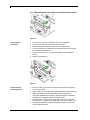
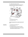
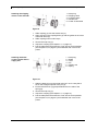
1
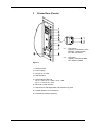
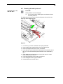
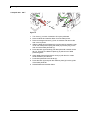
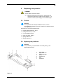
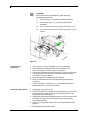
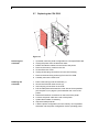
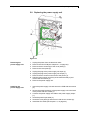
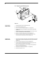
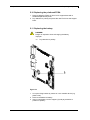
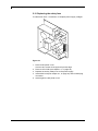
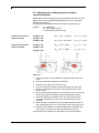
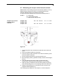
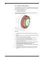
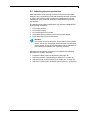
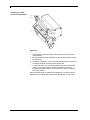
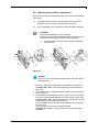
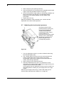
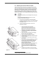
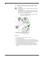
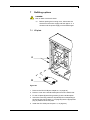
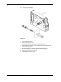
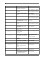
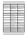
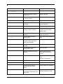
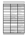
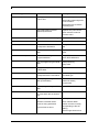
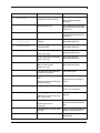
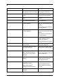
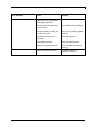
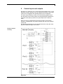
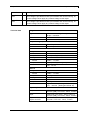
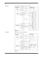
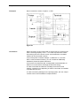
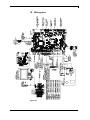
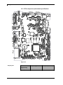
COMPA II Service Instructions Copyright by Carl Valentin GmbH / 7952025B.1115 Information on the scope of delivery, appearance, performance, dimensions and weight reflect our knowledge at the time of printing. We reserve the rights to make modifications. All rights, including those regarding the translation, are reserved. No part of this document may be reproduced in any form (print, photocopy or any other method) or edited, copied or distributed electronically without written permission from Carl Valentin GmbH. Due to the constant further development of our devices discrepancies between manual and device can occur. Please check www.carl-valentin.de for the latest update. Trademarks All named brands or trademarks are registered brands or registered trademarks of their respective owners and may not be separately labelled. It must not be concluded from the missing labelling that it is not a registered brand or a registered trademark. Carl Valentin label printers comply with the following safety guidelines: CE EG Low-Voltage Directive (2006/95/EC) EG Electromagnetic Compatibility Directive (2004/108/EC) Carl Valentin GmbH Postfach 3744 78026 Villingen-Schwenningen Neckarstraße 78 – 86 u. 94 78056 Villingen-Schwenningen Phone Fax +49 (0)7720 9712-0 +49 (0)7720 9712-9901 E-Mail Internet [email protected] www.carl-valentin.de Compa II series Table of contents Table of contents Table of contents .............................................................................. 3 1 1.1 1.2 1.3 2 2.1 2.2 3 Notes on this document ....................................................... 5 User notes ............................................................................... 5 Warnings ................................................................................. 5 Cross references ..................................................................... 6 Safety instructions ................................................................ 7 General safety instructions ...................................................... 7 Safety handling when working with electricity ......................... 9 Printer Rear (Ports) ............................................................. 10 4 4.1 4.2 4.3 4.4 5 5.1 5.2 5.3 5.4 5.5 5.6 5.7 5.8 5.9 5.10 5.11 5.12 6 6.1 6.2 6.3 6.4 6.5 6.6 6.7 6.8 6.9 6.10 7 7.1 7.2 7.3 8 Cleaning ............................................................................... 11 General cleaning ................................................................... 12 Cleaning the print roller ......................................................... 12 Cleaning the printhead .......................................................... 12 Cleaning the label photocell .................................................. 13 Replacing components ....................................................... 15 Tool list .................................................................................. 15 Replacing the printhead ........................................................ 15 Adjusting the Print Position ................................................... 17 Replacing the print roller and rewind assist roller ................. 18 Replacing the slipping clutches ............................................. 19 Replacing the label photocell ................................................ 21 Replacing the CPU PCB ....................................................... 22 Replacing the power supply unit ........................................... 23 Replacing the WLAN module ................................................ 24 Replacing the printhead FPGA.............................................. 25 Replacing the battery ............................................................ 25 Replacing the safety fuse ...................................................... 26 Adjustments, settings and alignments ............................. 27 Adjusting the winding torques ............................................... 27 Measuring the winding torques at ribbon rewinder/unwinder 28 Measuring the torques at the internal rewinder ..................... 29 Setting the winding torque ..................................................... 30 Adjusting the print mechanism .............................................. 31 Adjusting the position of printhead ........................................ 33 Adjusting the head contact pressure ..................................... 34 Adjusting the transfer ribbon feed path ................................. 35 Adjusting the belt tension at main drive motor ...................... 36 Adjusting the head switch ...................................................... 37 Refitting options .................................................................. 39 I/O plate ................................................................................. 39 Internal rewinder .................................................................... 40 Cutter ..................................................................................... 41 Error correction ................................................................... 43 9 Control inputs and outputs ................................................ 53 10 Wiring plan ........................................................................... 59 10.1 CPU component placement specification ............................. 60 11 Environmentally-Friendly Disposal ................................... 61 12 11.15 Index ..................................................................................... 63 Service instructions 3 Compa II series Notes on this document 1 Notes on this document 1.1 User notes This service manual is intended for qualified service and maintenance staff. This manual contains information about hardware and mechanical part of the label printers 103/8 T, 104/8, 106/12, 106/24, 108/12 T, 162/12 and 162/12 T. Information about operation of printer can be taken from our operating manual. If a problem arises that cannot be solved with help of this service of manual, then please contact your responsible dealer. 1.2 Warnings Warnings are presented with three signal words for the different levels of danger. DANGER identifies an extraordinarily great and immediate danger which could lead to serious injury or even death. WARNING identifies a possible danger would could lead to serious bodily injury or even death if sufficient precautions are not taken. CAUTION indicates a potentially dangerous situation which could lead to moderate or light bodily injury or damage to property. DANGER! Risk of death via electric shock! 11.15 Before opening the housing cover, disconnect the device from the mains supply and wait approx. 2 - 3 minutes until the power supply unit has discharged. Service instructions 5 Notes on this document Compa II series 1.3 Cross references Item numbers References to specific items in a figure are marked with item numbers. They are identified with parentheses in the text, e.g. (9). If no figure number is provided, item numbers in the text always refer to the graphic directly above the text. If a reference is made to another graphic, the figure number is specified, e.g. (2, in figure 5). Cross references to chapters and sections For a cross reference to chapters and sections, the chapter number and page number are specified, e.g. a reference to this section: see chapter 1.3.2, on page 35). References to other documents References to other documents have the following form: See 'operating manual'. 6 Service instructions 11.15 Compa II series Safety instructions 2 Safety instructions 2.1 General safety instructions Workplace and method of working Clothing Keep the area around the device clean during and after maintenance. Work in a safety-conscious manner. Store dismantled device parts in a safe place while maintenance is being performed. WARNING! The drawing in of items of clothing by moving parts can lead to injuries. If possible, do not wear clothing which could be caught by moving device parts. Button or roll up shirt or jacket sleeves. Tie or pin up long hair. Tuck the ends of scarves, ties and shawls into your clothing or secure them with non-conductive clips. DANGER! Risk of death from increased flow of current via metals parts which come into contact with the device. 11.15 Do not wear clothing with metal parts. Do not wear jewellery. Do not wear glasses with a metal frame. Service instructions 7 Safety instructions Protective clothing Protective equipment Compa II series If a possible danger to your eyes is present, wear protective goggles, especially in the following cases: when knocking in or knocking out pins and similar parts with a hammer when using spring hooks when loosening or inserting springs, snap rings and gripping rings when soldering when using solvents, cleaning agents or other chemicals WARNING! Risk of injury in case of missing or faulty protective equipment. 8 After performing maintenance work, attach all safety equipment (covers, safety precautions, ground cables etc.). Replace faulty parts and those which have become unusable. Service instructions 11.15 Compa II series Safety instructions 2.2 Safety handling when working with electricity Qualifications of personnel General precautions to be heeded when beginning maintenance Additional precautions to be heeded for devices with exposed energized parts Tools What to do in case an accident occurs 11.15 The following work may only be performed by instructed and trained electricians: work on the electrical assemblies work on the device while it is open and connected to the power supply. Locate the emergency-stop or power switch so that it can be actuated in case of an emergency. Unplug the device from the electrical outlet before performing the following work: removing or installing power supply units working in the immediate vicinity of exposed power supply parts mechanical inspection of power supply parts modifying the device circuits. Ensure that the device is de-energized. Give another person the task of remaining near the workplace. This person must be familiar with the location and operation of the emergency-stop and power switches and switch off the power if danger arises. Use only one hand while working on electrical circuits when a device is switched on. Hold the other hand behind your back or put it in your jacket pocket. This prevents the electricity from flowing through your body. To not use worn or damaged tools. Proceed in a very cautions and calm manner. Check the workplace for possible sources of danger, e.g. moist floors, defective extension cables, faulty protective conduction connections. Use only tools and testing equipment that is suitable for the respective task. Avoid endangering yourself. Switch the power off. Request medical help (emergency physician). Call for first aid if necessary. Service instructions 9 Compa II series Printer Rear (Ports) 3 Printer Rear (Ports) 6.1 - LED orange 6.1 - Lighting = Connection active 6.1 - Flashing = Data transfer 6.1 - Off = No connection 6.2 - LED green 6.2 - Lighting = Speed 100 MBit 6.2 - Off = Speed 10 MBit Figure 1 1 = Switch On/Off 2 = Power supply 3 = Plug-in for CF card 4 = USB interface 5 = Serial interface RS-232 5 = Pin 2 = TXD, Pin 3 = RXD, Pin 5 = GND, 5 = Pin 7 = CTS, Pin 8 = RTS 6 = Ethernet 10/100 interface 7 = USB host for USB keyboard and USB memory stick 8 = Parallel interface for Centronics 9 = External input/output (option) 11.15 Service instructions 10 Compa II series Cleaning 4 Cleaning DANGER! Risk of death via electric shock! Cleaning schedule Before opening the housing cover, disconnect the device from the mains supply and wait approx. 2 - 3 minutes until the power supply unit has discharged. Task Frequency General cleaning (see chapter 4.1, on page 12). As necessary. Cleaning print roller (see chapter 4.2, on page 12). Each time the label roll is changed or when the printout and label transport are adversely affected. Cleaning printhead (see chapter 4.3, on page 12). Direct thermal printing: Each time the label roll is changed. Thermal transfer printing: Each time the transfer ribbon is changed or when the printout is adversely affected. Cleaning label photocell (see chapter 4.4, on page 13). When the label roll is changed. WARNING! Risk of fire by easily inflammable label soluble! Tools and cleaning agents 11.15 When using label soluble, dust must be completely removed from the label printer and cleaned. NOTICE! For adjustments and simple installation work, use the accompanying hexagonal wrench located in the bottom section of the print unit. No other tools are required for the work described here. Service instructions 11 Cleaning Compa II series 4.1 General cleaning CAUTION! Abrasive cleaning agents can damage the label printer! Do not use abrasives or solvents to clean the outer surface of the label printer. Remove dust and paper fuzz in the printing area with a soft brush or vacuum cleaner. Clean outer surfaces with an all-purpose cleaner. 4.2 Cleaning the print roller A soiled print roll can lead to reduced print quality and can affect transport of material. 1. 2. 3. 4. Turn lever (1, Figure 2) counter clockwise to lift up the printhead. Remove labels and transfer ribbon form the label printer. Remove deposits with roller cleaner and a soft cloth. If the roller appears damaged, replace it (see chapter 5.3, on page 17). 4.3 Cleaning the printhead Printing can cause accumulation of dirt at printhead e.g. by colour particles of transfer ribbon, and therefore it is necessary to clean the printhead in regular periods depending on operating hours, environmental effects such as dust etc. CAUTION! Printhead can be damaged! Do not use sharp or hard objects to clean the printhead. Do not touch protective glass layer of the printhead. 1. Turn lever (1, Figure 2) counter clockwise to lift up the printhead. 2. Remove labels and transfer ribbon from the label printer. 3. Clean printhead surface with special cleaning pen or a cotton swab dipped in pure alcohol. 4. Allow printhead to dry for 2-3 minutes before commissioning the printer. 12 Service instructions 11.15 Compa II series Cleaning 4.4 Cleaning the label photocell Compa II 103 T, 104, 106 and 108 T CAUTION! Label photocell can be damaged! Do not use sharp or hard objects or solvents to clean the label photocell. The label photocell can become dirtied with paper dust and this can adversely affect label detection. Figure 2 1. 2. 3. 4. 5. 6. 7. 8. 11.15 Turn lever (1) counter clockwise to lift up the printhead. Remove labels and transfer ribbon from the label printer. Remove hexagonal wrench (5) from its retainer. Press the latch (3) and slowly pull label photocell outwards via the tab (4). Ensure that the label photocell cable is not tensioned by this. Clean label photocell and sensor units (2) with brush or cotton swab soaked in pure alcohol. Push label photocell back via tab (3) and set it. Push hexagonal wrench (5) into retainer. Reload labels and transfer ribbon. Service instructions 13 Cleaning Compa II series Compa II 162 + 162 T Figure 3 1. Turn lever (1) counter clockwise to lift up the printhead. 2. Remove labels and transfer ribbon from the label printer. 3. Remove hexagonal wrench (7) from its retainer and remove the rear cover of printer. 4. Slide the label photocell assembly onto the tab (5) toward the rear cover until it stops and unplug the cable (2) from the plug on the rear end of the label photocell (1). 5. Press the latch (6) and slowly pull label photocell outward via the tab (5). That way the distance plate (3) is pushed out of label photocell guide. 6. Clean label photocell and sensor units (4) with brush or cotton swab soaked in pure alcohol. 7. Push label photocell back via tab (5). 8. Press the latch (6) and push the distance plate (3) into the guide of the label photocell. 9. Reload labels and transfer ribbon. 14 Service instructions 11.15 Compa II series Replacing components 5 Replacing components DANGER! Risk of death via electric shock! Before opening the housing cover, disconnect the device from the mains supply and wait approx. 2 - 3 minutes until the power supply unit has discharged. 5.1 Tool list NOTICE! For adjustments and simple installation work, use the accompanying hexagonal wrench located in the bottom section of the print unit. Some service work requires other tools: Philips-head screwdriver, size 1 Hexagonal wrench 1.5 mm Torx screwdriver TX20 Snap ring pliers, ZGG 0 Spring scale 10 N Spring scale 25 N 5.2 Replacing the printhead NOTICE! The printhead (7) is preinstalled on a head plate (1) and aligned at the factory. 1 2 3 4 5 6 7 Head plate Plug connection Plug connection Screw Printing line Pins Printhead Figure 4 11.15 Service instructions 15 Replacing components Compa II series CAUTION! The printhead can be damaged by static electricity discharges and impacts! Set up printer on a grounded, conductive surface. Do not touch contacts on the plug connections (2, 3). Ground your body, e.g. by wearing a grounded wristband. Do not touch printing line (5) with hard objects or your hands. Figure 5 Removing the printhead 1. 2. 3. 4. Installing the printhead 1. Attach plug connections (2, 3). 2. Position printhead in printhead mounting bracket (9) in such a way that the pins (6) are secured in the corresponding holes in the printhead mounting bracket (9). 3. Lightly keep printhead mounting bracket (9) on the print roller with one finger and check for correct positioning of the printhead mounting bracket (9). 4. Screw in screw (8) with washer with the hexagonal wrench and tighten it. 5. Reload labels and transfer ribbon. 16 Turn lever (10) counter clockwise to lift up the printhead. Remove labels and transfer ribbon from the label printer. Remove hexagonal wrench (11) from its retainer. Lightly keep printhead mounting bracket (9) on the print roller with one finger and screw out screw (8) with the hexagonal wrench and remove it and the washer. 5. Swivel printhead mounting bracket (9) upwards. 6. Remove printhead from the printhead mounting bracket (9) if necessary. 7. Loosen both plug connections (2, 3) on the printhead and set printhead down on a clean, soft surface. Service instructions 11.15 Compa II series Replacing components 5.3 Adjusting the Print Position Press key Zero point adjustment in Y direction to access the function menu. Press key as long as you arrive the Service Functions menu. Press key to select the menu. Press key adjustment. as long as you arrive the menu item Zero point Indication of value in 1/100 mm. After replacing the printhead - the print cannot be continued at the same position on the label, the difference can be corrected in printing direction. NOTICE! The value for zero point adjustment is set ex works. After replacing the printhead, only service personnel are allowed to set this value anew. Press key Zero point adjustment in X direction to arrive the next menu item. Indication of value in 1/100 mm. After replacing the printhead - the print cannot be continued at the same position on the label, the difference can be corrected across the printing direction. NOTICE! The value for zero point adjustment is set ex works. After replacing the printhead, only service personnel are allowed to set this value anew. 11.15 Service instructions 17 Replacing components Compa II series 5.4 Replacing the print roller and rewind assist roller Figure 6 Removing the side plate 1. 2. 3. 4. Turn lever (1) counter clockwise to lift up the printhead. Lift the pinch roller (5) off the rewind assist roller. Remove labels and transfer ribbon from the label printer. Loosen screws (4) on plate (6) with hexagonal wrench by several turns and remove plate (6). 5. Unscrew screws (3a, b, c) of the side plate (2) with hexagonal wrench. 6. Remove side plate (2). Figure 7 Removing and installing rollers 18 1. Pull print roller (7) and rewind assist roller (8) from the shafts (9, 10) on the housing. 2. Clean shafts (9, 10) of the rollers (see expanded view at shaft 10). 3. Slide print roller (7) and rewind assist roller (8) onto their respective shafts and turn slightly until the hexagon of the shaft engages in the hexagon socket of the print roller. 4. Set side plate (2, Figure 6) in place and screw it down with the screws (3a, b, c, Figure 6) by tightening the screws in order a-b-c.. 5. Set plate (6, Figure 6) in place and tighten screws (4, Figure 6) with hexagonal wrench. Service instructions 11.15 Compa II series Replacing components 5.5 Replacing the slipping clutches The rewinder for the transfer ribbon and the internal rewinder are coupled to slipping clutches in the main drive. The supply hub of the transfer ribbon is braked with a slipping clutch during printing. Figure 8 1 = Transfer ribbon supply hub: brake 2 = Transfer ribbon take up hub: coupling 3 = Internal rewinder: coupling Change the slipping clutch when it can no longer be set. Removal and installation of the slipping clutch is also required for replacement of a winder. Removing the slipping clutch 11.15 1. 2. 3. 4. 5. Unplug the printer from the electrical outlet. Remove the rear cover of the printer. Remove the snap ring (1). Pull coupling or brake (2) from the winder axis (4, Figure 9). Ensure that the pin (4, Figure 23) remains on the winder axis when pulling the brake off. Reattach the pin to the winder axis if it has been pulled off. The axis profile is shaped in such a way that the pin only fits on the winder axis in one way. Service instructions 19 Replacing components Compa II series 1 = Snap ring 2 = Slipping clutch 3 = Coupling disks 4 = Winder axis 5 = Collar of belt wheel Installing the slipping clutch on the rewinder Figure 9 1. Slide coupling (2) onto the winder axis (4). 2. Align grooves in the coupling disks (3) with the guides in the collar of the belt wheel (5). 3. Slide coupling further until it stops. 4. Secure the snap ring (1). 5. Adjust the coupling (see chapter 6.1, on page 27). 6. Pull the label photocell toward the cover side as far as possible (see chapter 5.6, on page 21) and install the rear cover of the printer. 1 = Snap ring 2 = Brake 3 = Lever 4 = Pin 5 = Winder acis 6 = Spring Installing the brake on the transfer ribbon supply hub Figure 10 1. Slide the brake (2) onto the winder axis (5) in such a way that it fits on the hexagonal profile of the pin (4). 2. Ensure that the lever (3) grasps between the two ends of the spring (6). 3. Secure the snap ring (1). 4. Adjust the coupling (see chapter 6.1, on page 27). 5. Pull the label photocell toward the cover side as far as possible (see chapter 5.6, on page 21) and install the rear cover of the printer. 20 Service instructions 11.15 Compa II series Replacing components 5.6 Replacing the label photocell NOTICE! Soiling of the label photocell can also cause malfunctions. Before replacing the label photocell, check whether it is soiled and clean it if necessary (see chapter 4.4, page 13). Figure 11 Removing label photocell 1. 2. 3. 4. Installing the label photocell 1. Insert the label photocell (1) into the guide from the cover side and slide it onto the tab (5) toward the rear cover until it stops. Compa II 162 + 162 T: Push the distance plate (3) into the guide of the label photocell. 2. Remount the side plate (7) with screws (5a, b, c) by tightening the screws in order, i.e. a, b then c. 3. Connect the cable (2) to the label photocell (1). 4. Pull the label photocell (1) via the tab (4) as far as possible toward the cover side. This prevents the cable (2) from being pinched when installing the rear cover. 5. Install the rear cover of the printer. 6. Insert the hexagonal wrench (6) into its retainer. 7. Adjust the label photocell. 11.15 Remove media from the printer. Remove the hexagonal wrench (6) from its retainer. Remove the rear cover of the printer. Slide the label photocell assembly onto the tab (4) toward the rear cover until it stops. 5. Unplug the cable (2) from the plug on the rear end of the label photocell (1). 6. Unscrew the screws (5a, b, c) with a hexagonal wrench and remove the side plate (7). 7. Pull out the label photocell (1) via the tab (4) toward the cover side. Compa II 162 + 162 T: That way the distance plate (3) is pushed out of label photocell guide. Service instructions 21 Replacing components Compa II series 5.7 Replacing the CPU PCB Figure 12 Removing the CPU PCB 1. 2. 3. 4. 5. 6. 7. 8. If possible, save the printer configuration to a CompactFlash card. Unplug the printer from the electrical outlet. Detach all interface cables from the back of the printer. Remove the memory card from the slot. Screw off the rear cover. Unplug all side plug connections from the CPU PCB (2). Remove the three fixing screws (3) from the CPU PCB. Carefully remove the CPU PCB. Installing the CPU PCB 1. 2. 3. 4. Place CPU PCB (2) onto the retainers (1). Secure the PCB with three screws (3). Insert all plug connections on the PCB. Pull the label photocell toward the cover side as far as possible (see chapter 5.6, on page 21) and install the rear cover of the printer. Restore all interface connections on the back of the printer. Connect the power cable at the rear of the printer. Update the firmware if necessary. Adjust the label photocell. Load the printer configuration from the memory card if possible. Otherwise, set the printer configuration via the operating panel. 5. 6. 7. 8. 9. 22 Service instructions 11.15 Compa II series Replacing components 5.8 Replacing the power supply unit Figure 13 Removing the power supply unit 1. 2. 3. 4. 5. 6. 7. 8. Installing the power supply unit 1. Insert the power supply unit and secure the PCB with two screws (2). 2. Secure the metal bracket (4) of the power supply unit to the back of the printer with two screws (7). 3. Connect the power supply unit cable to the power supply output (1). 4. Insert the power input cable (3). 5. Insert the cover plate (5) and secure it with the two screws (6). 6. Install the CPU PCB (see chapter 5.7, on page 22). 11.15 Unplug the printer from the electrical outlet. Remove the CPU PCB (see chapter 5.7, on page 22). Remove the two screws (6) of the cover plate (5). Remove the cover plate (5). Unplug the plug at the power supply unit input (3). Unplug the plug at the power supply unit output (1). Remove the two screws on the back of the printer (7). Hold the power supply unit firmly at the metal bracket (4) and remove the two screws (2). 9. Remove the power supply unit. Service instructions 23 Replacing components Compa II series 5.9 Replacing the WLAN module C D C D (B) A B J G M G G K E I F CPU I H L H Figure 14 Removing the WLAN module 1. Unplug the printer from the electrical outlet. 2. Screw off the left printer cover. 3. Remove the CPU PCB (see chapter 5.7, on page 22). 4. Loosen hex-nuts (H) and washers (I) and dismount the WLAN adapter (F). 5. Remove hot melt glue from WLAN module (M) and then remove antenna cable (B) from WLAN module (M). 6. Remove connecting cable (E) from WLAN adapter (F). 7. Dismount screws (J), spacer rings (K) and hex nuts (L) and remove WLAN module (M) from WLAN adapter (F). Installing the WLAN module 1. Insert the new WLAN module (M) to the WLAN adapter (F) and fix it with screws (J), spacer rings (K) and hex nuts (L) at the WLAN adapter (F). 2. Insert connection cable (E) in the WLAN adapter (F). 3. Connect antenna cable (B) with WLAN module (M) and fix the plug connectors with a drop of hot melt glue. 4. Mount the WLAN adapter (F) to the hexagon bolt (G) and fix it with hex nuts (H) and screws (I). 5. Install the CPU PCB (see chapter 5.7, on page 22). 6. Install the left printer cover. 24 Service instructions 11.15 Compa II series Replacing components 5.10 Replacing the printhead FPGA 1. Remove defective FPGA (2) from PLCC support base with a suitable displacement pincer. 2. Pay attention to polarity and press the new FPGA into the support base. 5.11 Replacing the battery DANGER! Danger of explosion when exchanging the battery improper. Pay attention to polarity. Figure 15 1. Lift up the fixing bracket by means of a non-metallic device (e.g. plastic ruler). 2. Remove the defective battery. 3. Insert a new battery into the support (A) and pay attention to position of polarity. 11.15 Service instructions 25 Replacing components Compa II series 5.12 Replacing the safety fuse F1: Microfuse 10A/T = Protection of complete power supply voltages Figure 16 1. Remove left printer cover. Unscrew two screws at the upper left printer edge. 2. Remove CPU PCB (see chapter 5.7, on page 22). 3. Replace secondary safety fuse on the power supply. 4. Install CPU PCB (see chapter 5.7, on page 22) and recreate plug connexion. 5. Attach again the left printer cover. 26 Service instructions 11.15 Compa II series Adjustments, settings and alignments 6 Adjustments, settings and alignments DANGER! Risk of death via electric shock! Before opening the housing cover, disconnect the device from the mains supply and wait approx. 2 - 3 minutes until the power supply unit has discharged. 6.1 Adjusting the winding torques The rewinder for the transfer ribbon and the internal rewinder are coupled to slipping clutches in the main drive. The supply hub of the transfer ribbon is braked with a slipping clutch during printing. The correct setting of the torques of these slipping clutches is necessary for: precise conveyance of the transfer ribbon during label transport the prevention of wrinkles in the feed path of the transfer ribbon sufficiently tight peel-off tension of the liner and thus easy peeling off of labels in peel-off mode a sufficiently tightened label strip The winding axes of the rewinder are not actively driven by the belts during label backfeed, but rather solely by the pull of the print roller. The torque required to decouple the rewinder from the belt drive is implemented via a brake in the winding reel, which works in both directions. The measured clockwise torque is the sum of the coupling torque and the torque of the brake. Only the torque of the brake is measured when the winding axis is rotating counter clockwise. For this reason, measurement of the torques at the rewinders is required in both directions. The type of measurement differs for the various types of slipping clutches: measurement of the winding torques at the transfer ribbon rewinder and unwinder (see chapter 6.2, on page 28) measurement of the winding torque at the internal rewinder (see chapter 6.3, on page 29). If the winding torque differs from the setpoint, it must be adjusted. The procedures for adjusting the winding torques of the transfer ribbon winders and the internal rewinder are identical. 11.15 Service instructions 27 Adjustments, settings and alignments Compa II series 6.2 Measuring the winding torques at ribbon rewinder/unwinder Measurement of the winding torque at the transfer ribbon take up and supply hub occurs by determining the pulling forces on a test collar attached to the winder. The physical relation between the torque and the pulling force is: F=M/r Setpoints for transfer ribbon rewinder Setpoints for transfer ribbon unwinder F = traction [N] M = rewind torque [Ncm] r = radius of test collar (30 mm) Compa II 104, Compa II 106: MAuf = 13,5 - 15,0 Ncm FAuf = 4,5 - 5,0 N Compa II 162: MAuf = 21,0 - 22,5 Ncm FAuf = 7,0 - 7,5 N Compa II 104, Compa II 106: MAb = 4,0 - 4,5 Ncm FAb = 1,3 - 1,5 N Compa II 162: MAb = 6,0 - 7,0 Ncm FAb = 2,0 - 2,3 Figure 17 1. Unplug the printer from the electrical outlet and remove the rear cover. 2. Remove the transfer ribbon from the printer. 3. Attach the test collar (3) to the winder (4). 4. Turn the knurled nut counter clockwise to clamp the test collar. 5. Wind the cord attached to the test collar around the test collar several times. 6. Secure spring scale [10 N] (1) at the end of the cord and move the spring scale upward vertically until the winder begins turning. 7. If the drive belt at the rewinder is also moving, hold it in place during the measurement. Otherwise, the measurement is not accurate. 8. Allow the cord to unwind from the test collar at least one full turn and read the pulling force F on the spring scale at the same time. 9. Determine the pulling force at the transfer ribbon rewinder in the same manner, except in the opposite rotation direction (2). If the winding torque differs from the setpoint, it must be adjusted. 28 Service instructions 11.15 Compa II series Adjustments, settings and alignments 6.3 Measuring the torques at the internal rewinder Measurement of the winding torque at the internal rewinder occurs by determining the pulling forces with a cord wrapped around the rewinder. Measurement occurs without a test collar. The physical relation between the torque and the pulling force is: F=M/r Setpoints for internal transfer ribbon rewinder F = traction [N] M = rewind torque [Ncm] r = radius of test collar (20 mm) Compa II 104, Compa II 106: MAuf = 28 - 32 Ncm FAuf = 14 - 16 N Compa II 162: MAuf = 36 - 44 Ncm FAuf = 18 - 22 N Figure 18 1. Unplug the printer from the electrical outlet and remove the rear cover. 2. Remove the label media from the printer. 3. Push the cord (2) under a bracket of the internal rewinder (3) and wind it around the rewinder. 4. Secure spring scale [25 N] (1) at the end of the cord. 5. Move the spring scale (1) upward vertically until the winder begins turning. 6. If the drive belt is also moving, hold it in place during the measurement. Otherwise, the measurement is not accurate. 7. Allow the cord to unwind from the test collar at least one full turn and read the pulling force F on the spring scale at the same time. 8. Determine the pulling force in the same manner, except in the opposite rotation direction (4). If the winding torque differs from the setpoint, it must be adjusted. 11.15 Service instructions 29 Adjustments, settings and alignments Compa II series 6.4 Setting the winding torque The winding torque of a winder can be changed at the knurled ring of the respective slipping clutch. The numbers on the knurled ring stand for the value of the winding torque: 1: Smallest winding torque 7: Greatest winding torque The current setting value is indicated by the number located at the positions of the two locking tabs. Figure 19 1. Unplug the printer from the electrical outlet and remove the rear cover. 2. Press the knurled ring (1) of the slipping clutch toward the housing wall. The lock (2) of the knurled ring is released. 3. Turn the knurled ring to the desired position while pushing it. 4. Release the knurled ring in the desired position. 5. Ensure that the tabs of the lock are located completely in the grooves of the setting value. 6. Measure the winding torque again and compare it to the setpoint. Transfer ribbon winders (see chapter 6.2, on page 28) Internal rewinder (see chapter 6.3, on page 29). 7. Repeat the adjustment until the measured winding torque is within the tolerance range. 8. Pull the label photocell toward the cover side as far as possible (see chapter 5.6, on page 21) and install the rear cover of the printer. 30 Service instructions 11.15 Compa II series Adjustments, settings and alignments 6.5 Adjusting the print mechanism Major adjustment of the printing mechanism beyond format-based settings is only required if the printhead assembly has been removed or parts in this area have been replaced. Excluded from this is the replacement of the printhead, after which readjustment is generally not required. The following print quality imperfections may indicate maladjustment of the printing mechanism: Print image too light Print image is spotty Print image lighter on one side Horizontal lines not parallel to the horizontal label edges Clear lateral drift of the transfer ribbon NOTICE! Print image errors can also arise from wrinkling of the transfer ribbon. This is why the transfer ribbon feed path and the head locking system should be checked before making adjustments to the printing mechanism (see 'operating manual'). Adjustment of the printing mechanism encompasses the following procedures in the order specified: 1. 2. 3. 4. 11.15 Prepare the label printer for adjustment (see page 32). Adjust the position of printhead (see chapter 6.6, on page 33). Adjust the head contact pressure (see chapter 6.7, on page 34). Adjust the transfer ribbon feed path (see chapter 6.8, on page 35). Service instructions 31 Adjustments, settings and alignments Compa II series Preparing the label printer for adjustment Figure 20 1. Load labels and transfer ribbon which extend across the entire printing width. 2. Move the transfer ribbon deflection to the central position (3) with the screw (2). 3. Position the plunger in such a way that the adjustment screws are accessible through the holes of the square axis. 4. Loosen the screw (1) for the printhead bowing with a hexagonal wrench (1.5 mm) and turn it counter clockwise until turning becomes perceptibly easier. This should occur after a maximum of a half a rotation. When the label printer is prepared for adjustment, continue with the adjustment of the printhead position (see chapter 6.6, on page 33). 32 Service instructions 11.15 Compa II series Adjustments, settings and alignments 6.6 Adjusting the position of printhead Complete the following printhead settings to achieve the best possible print image: Align the heating line with the highest point of the print roller. Density of the print image is the greatest at this point. Set the parallelism of horizontal lines with the edge of the label. CAUTION! The printhead assembly can be damaged. Attempting to adjust the printhead when the fixing screw (3) is tight can lead to defects at the printhead assembly. Always loosen the fixing screws (3) before adjusting the printhead. Figure 21 NOTICE! Open and close the printhead locking device after each step of the adjustment. 1. Check the alignment of printhead in the adjustment windows (1). Compa II 162 + 162 T: Check the alignment of printhead at the slides (5). 2. If the printhead is not aligned properly, loosen the screw (3) about one quarter turn. 3. If the printhead is not aligned properly, use the screws (2) to align the lines on the printhead with the tips of the grooves and/or with Compa II 162 + 162 T to align the lines on the printhead mounting bracket with the front edge of the slides (5). Screw (2a) effects the inner half of the printhead, and screw (2b) the outer half. Turning clockwise moves the printhead forward. Compa II 162 + 162 T: Turning clockwise moves the printhead backward. 11.15 Service instructions 33 Adjustments, settings and alignments Compa II series 4. Start a test print (see 'operating manual'). 5. If the horizontal lines in the test grid are not parallel with the label edges, adjust the parallelism with the screws (2). 6. Set the best possible image quality by maintaining parallelism via turning the screws (2a) and (2b) in an alternating fashion. Differences in the density between the two sides are still permissible. 7. Tighten the screw (3). When the parallelism of the printhead is set, continue with the adjustment of the head contact pressure. 6.7 Adjusting the head contact pressure Change the head contact pressure with the screws (1a) and (1b) at the inside and outside of the printhead. Increasing the head contact pressure leads to an improvement of the print image density on the corresponding side and to a shifting of the ribbon feed path in the corresponding direction. Figure 22 1. Turn the adjustment screws (1) counter clockwise until turning becomes perceptibly easy. 2. The contrast value (in function menu) is to be reduced in the printer configuration until the print image is only barely recognizable. Under these conditions, inaccuracies become clearly visible during adjustment. 3. Start a test print (see 'operating manual'). 4. Adjust the adjustment screw (1a or 1b) clockwise in small increments on the side with the weaker print image until the print image is even across the entire width. It may happen that both adjustment screws must be turned in an alternating fashion, resulting in a print image which is too light overall. When the print image is set evenly, continue with setting of the transfer ribbon feed path (see chapter 6.8, on page 35). 34 Service instructions 11.15 Compa II series Adjustments, settings and alignments 6.8 Adjusting the transfer ribbon feed path* Adjust the transfer ribbon feed path by changing the head contact pressure and adjusting the transfer ribbon deflection. Increasing the head contact pressure with the screws (3a) and (3b) shifts the ribbon feed path in the corresponding direction. The skew of the transfer ribbon deflection is used to suppress wrinkles in the transfer ribbon feed path. Wrinkles which cannot be remedied with the skew of the transfer ribbon deflection can be suppressed by bowing the printhead. CAUTION! The printhead assembly can be damaged when bowing the printhead. Turning the adjustment screw (1) too hard can cause damage to the printhead assembly. As soon as a clear resistance is perceived when turning the adjustment screw (1), only continue turning the screw in very small increments, but no more than one eighth of a turn. Only turn the adjustment screw (1) as far as is absolutely necessary. 1. Check the transfer ribbon feed path. The wound up ribbon should be the same distance from the disk of the winder as the supply roll is from the disk of the rewinder. 2. If the ribbon runs inward or outward, turn the corresponding screw (3a) or (3b) clockwise in small increments. 3. Wait until the ribbon feed path has stabilized after each step of the adjustment. 4. Check the ribbon feed path for wrinkles. 5. If wrinkles arise on the inside, turn the screw (2) counter clockwise. 6. If wrinkles arise on the outside, turn the screw (2) clockwise. 7. If the wrinkles cannot be remedied (e.g. wrinkles in the centre), turn the adjustment screw (1) clockwise with extreme care (see warnings) using a hexagonal wrench (1.5 mm) and observe the ribbon feed path. When the adjustment screw (1) is tightened, the printhead is bent downward slightly in the centre. It is possible that a slight lightening at the edge areas of the print image could occur here. 8. If bowing is not necessary, turn the screw (2) clockwise until the screw is just barely clamping. Figure 23 * 11.15 only for Compa II 104/8, 106/12, 106/24, 162/12 Service instructions 35 Adjustments, settings and alignments Compa II series 6.9 Adjusting the belt tension at main drive motor CAUTION! The toothed belt could be damaged if adjustment is carried out improperly. Improper adjustment or insufficient tension of the toothed belt could cause it to rub against the label photocell during printing, which would damage the belt. Tension the toothed belt in such a way that it cannot rub against the label photocell. Figure 24 1. 2. 3. 4. Unplug the printer from the electrical outlet. Remove the rear cover. Loosen the three fixing screws (4) of the main drive motor (3). Swivel the main drive motor (3) in such a way that the toothed belt (2) is tensioned tightly between the motor and the print roller (1). 5. Tighten the fixing screws (4) in this position of the motor. 6. Pull the label photocell toward the cover side as far as possible (see chapter 5.6, on page 21) and install the rear cover of the printer. 36 Service instructions 11.15 Compa II series Adjustments, settings and alignments 6.10 Adjusting the head switch The head switch prevents printing from occurring when the printhead is open. Figure 25 1. 2. 3. 4. 5. Unplug the printer from the electrical outlet. Remove the rear cover. Lock printhead. Slightly loosen the fixing screws (3) of the head switch (2). Move the head switch housing and switching lever (1) to a parallel position (see magnified cut-out). 6. Screw down the head switch in this position. 7. Pull the label photocell toward the cover side as far as possible (see chapter 5.6, on page 21) and install the rear cover of the printer. 11.15 Service instructions 37 Compa II series Refitting options 7 Refitting options DANGER! Risk of death via electric shock! Before opening the housing cover, disconnect the device from the mains supply and wait approx. 2 - 3 minutes until the power supply unit has discharged. 7.1 I/O plate A B Figure 26 1. Remove the CPU PCB (see chapter 5.7 on page 22). 2. Remove cover at the interface disruption from the chassis rear. 3. Fix the I/O plate (B) with fixing screws (A) at the aft disruption. 4. Insert the connecting cables for inputs/outputs corresponding to the wiring plan (see chapter 10, on page 59) into the appropriate plug-in positions of the I/O plate. 5. Install the CPU PCB (see chapter 5.7, on page 22). 11.15 Service instructions 39 Refitting options Compa II series 7.2 Internal rewinder Figure 27 1. Remove label material. 2. Remove left printer cover. Unscrew two screws at the upper left printer edge. 3. Remove black protective cap in order to use the opening for the internal rewinding unit. 4. Mount the single components of internal rewinding unit in illustrated order from front through the chassis opening. 5. Build the illustrated course of belt. 6. Attach again the printer cover. 40 Service instructions 11.15 Compa II series Refitting options 7.3 Cutter CAUTION! Risk of injury, particularly during maintenance, the cutter blades are sharp! Switch off the before attaching the cutter! The cutter may only be used when it is mounted on the printer! Do not try to cut any materials which exceed the maximum width or thickness specifications. Do NOT touch the area of the moving blades! 1. Open the right printer cover. 2. Remover lower front plate. 3. Insert cutter unit with guiding pilots in the appropriate guiding holes. Take care of plug-in connector! 4. Fix cutter unit with knurled screw at chassis. 5. Tighten front plate with enclosed hex-nut and washer at right cover. 6. Insert label material (see 'operating manual'). 11.15 Service instructions 41 Compa II series Error correction 8 Error correction Error message Cause Remedy 1 Line rises up completely or partly over the upper edge of label. Move line down (increase Y value). Line rises up completely or partly over the bottom edge of label. Move line up (reduce X value). One res. several characters of the text is res. are not available in the selected font. Change text. 2 3 Line too high Line too low Character set Check rotation and font. Check rotation and font. Change font. 4 Unknown code type Selected code is not available. Check code type. 5 Unvalid position Selected position is not available. Check position. 6 CV font Selected font is not available. Check font. 7 Vector font Selected font is not available. Check font. 8 Measuring label While measuring no label was found. Check label length and if labels are inserted correctly. Set label length is too large. Restart measuring anew. No label available. Insert new label roll. Soiled label photocell. Check if labels are inserted correctly. 9 No label found Labels not inserted correctly. Clean the label photocell. 10 No ribbon During the print order the ribbon roll becomes empty. Defect at the transfer ribbon photocell. 11 COM FRAMING Stop bit error. Change transfer ribbon. Check transfer ribbon photocell (service functions). Check stop bits. Check baud rate. Check cable (printer and PC). 12 COM PARITY Parity error. Check parity. Check baud rate. Check cable (printer and PC). 13 11.15 COM OVERRUN Loss of data at serial interface (RS-232). Service instructions Check baud rate. Check cable (printer and PC). 43 Error correction Compa II series Error message Cause Remedy 14 Received line number is invalid at RS-232 and Centronics. Check sent data. Invalid length of received mask statement. Check sent data. Transferred mask statement is invalid. Check sent data. No end of data found. Check sent data. 15 16 17 Field numer Length mask Unknown mask Missing ETB Check connection PC - printer. Check connection PC - printer. Check connection PC - printer. Check connection PC - printer. 18 19 20 Invalid character Invalid statement Invalid check digit One res. several characters of the text is res. are not available in the selected font. Change text. Unknown transferred data record. Check sent data. For check digit control the entered res. received check digit is wrong. Calculate check digit anew. Change font. Check connection PC - printer. Check code data. 21 Invalid SC number Selected SC factor is invalid for EAN res. UPC. Check SC factor. 22 Invalid number of digits Entered digits for EAN res. UPC are invalid Check number of digits. < 12; > 13. 23 Check digit calculation Selected check digit calculation is not available in the bar code. Check calculation of check digit. Check bar code type. 24 Invalid extension Selected zoom factor is not available. Check zoom factor. 25 Offset sign Entered sign is not available. Check offset value. 26 Offset value Entered offset value is invalid. Check offset value. 27 Printhead temperature Printhead temperature is too high. Reduce contrast. Change printhead. Defective printhead sensing device. 28 29 44 Cutter error Invalid parameter With cut an error occurred. Check label run. Paper jam. Check cutter run. Entered data do not correspond to the characters allowed from the application identifier. Check code data. Service instructions 11.15 Compa II series Error correction Error message Cause Remedy 30 Application Identifier Selected application identifier is not available in GS1-128. Check code data. 31 HIBC definition F Missing HIBC system sign. Check definition of HIBC code. Missing primary code. 32 System clock Real Time Clock function is selected but the battery is empty. Change battery. Change RTC component. Defective RTC. 33 No CF interface Interrupted connection CPU CF card. Check connection CPU - CF card interface. Defective CF card interface. Check CF card interface. 34 No print memory No print CF found. Check CF assembly on CPU. 35 Cover open At start of a print order the printhead is open. Close the printhead and start print order anew. 36 BCD invalid format BCD error Check entered format. Invalid format for the calculation of Euro variable. 37 BCD overflow BCD error Check entered format. Invalid format for the calculation of Euro variable. 38 BCD division BCD error Check entered format. Invalid format for the calculation of Euro variable. 39 FLASH ERROR Flash component error. Run a software update. Change CPU. 40 Length command Invalid length of the received command statement. Check data sent. Check connection PC - printer. 41 No drive CF card not found / not correctly inserted. Insert CF card correctly. 42 Drive error Impossible to read CF card (faulty). Check CF card, if necessary change it. 43 Not formatted CF Card not formatted. Format CF card. 44 Delete current directory Attempt to delete the actual directory. Change directory. 45 Path too long Too long indication of path. Indicate a shorter path. 11.15 Service instructions 45 Error correction Compa II series Error message Cause Remedy 46 Drive writeprotected Memory card is write-protected. Deactivate write protection. 47 Directory not file Attempt to indicate a directory as file name. Correct your entry. 48 File already open Attempt to change a file during an access is active. Select another file. 49 No file/directory File does not exist on CF card. Check file name. 50 Invalid file name File name contains invalid characters. Correct entry of name, remove special characters. 51 Internal file error Internal file system error. Please contact your distributor. 52 Root full The max. number (64) of main directory entries is reached. Delete at least one main directory entry and create subdirectories. 53 Drive full Maximum CF capacity is reached. Use new CF Card, delete no longer required files. 54 File/directory exists The selected file/directory already exists. Check name, select a different name. 55 File too large During copying procedure not enough memory space onto target drive available. Use a larger target card. 56 No update file Errors in update file of firmware. Start update file anew. 57 Invalid graphic file The selected file does not contain graphic data. Check file name. 58 Directory not empty Attempt to delete a not empty directory. Delete all files and subdirectories in the desired directory. 59 No interface No CF card drive found. Check connection of CF card drive. Contact your distributor 60 No CF card No CF card is inserted. Insert CF card in the slot. 61 Webserver error Error at start of web server. Please contact your distributor. 62 Wrong FPGA The direct print module is equipped with the wrong FPGA. Please contact your distributor. 63 End position The label length is too long. Check label length res. the number of labels per cycle. The number of labels per cycle is too much. 46 Service instructions 11.15 Compa II series Error correction Error message Cause Remedy 64 Zero point Defective photocell. Change photocell. 65 Compressed air Pressure air is not connected. Check pressure air. 66 External releaser External print release signal is missing. Check input signal. 67 Row too long Wrong definition of column width res. number of columns. Reduce the column width res. correct the number of columns. 68 Scanner The connected bar code scanner signals a device error. Check the connection scanner/printer. Check scanner (dirty). 69 Scanner NoRead Bad print quality. Increase contrast. Printhead completely soiled or defective. Clean printhead or exchange (if necessary). Print speed too high. Reduce print speed. 70 Scanner data Scanned data does not correspond to the data which is to print. Exchange printhead. 71 Invalid page As page number either 0 or a number > 9 is selected. Select a number between 1 and 9. 72 Page selection A page which is not available is selected. Check the defined pages. 73 Page not defined The page is not defined. Check the print definition. 74 Format user guiding Wrong format for customised entry. Check the format string. 75 Format date/time Wrong format for date/time. Check the format string. 76 Hotstart CF No CF card found. If option hotstart was activated, a CF card must be inserted. Switch off the printer before inserting the memory card. 77 Flip/Rotate Selection of print of several columns and also mirror/rotate. It is only possible to select one of both functions. 78 System file Loading of temporary hotstart files. Not possible. 79 Shift variable Faulty definition of shift times Check definition of shift times. (overlapping times). 80 GS1 Databar General GS1 Databar error. Check definition and parameter of GS1 Databar code. 81 IGP error Protocol error IGP. Check sent data. 11.15 Service instructions 47 Error correction Compa II series Error message Cause Remedy 82 Printing creation was still active at print start. Reduce print speed. Time generation Use printers' output signal for synchronisation. Use bitmap fonts to reduce generating time. 83 Transport protection Both DPM position sensors (start/end) are active. Displace zero point sensor Check sensors in service functions menu 84 No font data Font and web data is missing. Run a software update. 85 No layout ID Label ID definition is missing. Define label ID onto the label. 86 Layout ID Scanned data does not correspond to defined ID. Wrong label loaded from CF card. 87 RFID no label RFID unit cannot recognise a label. Displace RFID unit or use an offset. 88 RFID verify Error while checking programmed data. Faulty RFID label. Error at programming the RFID label. Label positioning. 89 RFID timeout Check RFID definitions Faulty label. 90 RFID data Faulty or incomplete definition of RFID data. Check RFID data definitions. 91 RFID tag type Definition of label data does not correspond with the used label. Check storage partitioning of used label type 92 RFID lock Error at programming the RFID label (locked fields). Check RFID data definitions. Check RFID definitions. 93 RFID programming Error at programming the RFID label. 94 Scanner timeout The scanner could not read the bar code within the set timeout time. Label was already programmed. Defective printhead. Check printhead. Wrinkles in transfer ribbon. Check transfer ribbon. Scanner wrong positioned. Position scanner correctly, corresponding to the set feeding. Timeout time too short. Select longer timeout time. 48 Service instructions 11.15 Compa II series Error correction Error message Cause Remedy 95 Scanner layout difference Scanner data does not correspond to bar code data. Check adjustment of scanner. 96 COM break Serial interface error. Check settings for serial data transmission as well as cable (printer-PC). 97 COM general Serial interface error. Check settings for serial data transmission as well as cable (printer-PC). 98 No software printhead FPGA No printhead-FPGA data available. Please contact your responsible distributor. 99 Load software printhead FPGA Error when programming printhead-FPGA. Please contact your responsible distributor. 100 Upper position Sensor signal up is missing Check input signals / compressed-air supply. (option APL 100). 101 Lower position Sensor signal down is missing (option APL 100). 102 Vacuum plate empty Sensor does not recognise a label at vacuum plate Check scanner settings / connection. Check input signals / compressed-air supply. Check input signals / compressed-air supply. (option APL 100). 103 Start signal Print order is active but device not ready to process it. Check start signal. 104 No print data Print data outside the defined label. Check selected module type. Selection of wrong module type (design software). 105 Printhead No original printhead is used. Check selection of left/right version. Check the used printhead. Contact your distributor. 106 Invalid Tag type Wrong Tag type. Tad data do not match the Tag type in the printer. 107 RFID invalid RFID module is not activated. No RFID data can be processed. Adapt data or use the correct Tag type. Activate RFID module or remove RFID data from label data. 108 GS1-128 invalid Transferred GS1-128 bar code is invalid. Verify bar code data (see GS1128 bar code specification). 109 EPC parameter Error at EPC calculation. Verify data (see EPC specification). 11.15 Service instructions 49 Error correction Compa II series Error message Cause Remedy 110 Housing open When starting the print order the housing cover is not closed. Close the housing cover and start the print order anew. 111 EAN.UCC code Transferred EAN.UCC code is invalid. Verify bar code data (see corresponding specification). 112 Print carriage Printing carriage does not move. Check gear belt (possibly broken). 113 Applicator error Error while using applicator. Check applicator. 114 Left position Left final position switch is not in correct position. Check LEFT final position switch for correct function and position. Check function of pneumatics for cross traverse. 115 Right position Right final position switch is not in correct position. Check RIGHT final position switch for correct function and position. Check function of pneumatics for cross traverse. 116 Print position The print position is not correct. Check TOP and RIGHT final position switch for correct function and position. Check pneumatics for function 117 XML parameter The parameters in the XML file are not correct. Please contact your responsible distributor. 118 Invalid variable Transferred variable is invalid with customized entry. Select correct variable without customized entry and transfer it. 119 No ribbon During the print order the ribbon roll becomes empty. Change transfer ribbon. Defect at the transfer ribbon photocell. 120 Wrong directory Invalid target directory when copying. Check transfer ribbon photocell (service functions). Target directory must not be within the source directory. Check target directory. 121 No label found No label found at the rear printhead (DuoPrint). Soiled label photocell. Labels not inserted correctly. 122 50 IP occupied The IP address was already assigned. Service instructions Insert new label roll. Clean the label photocell. Check if labels are inserted correctly. Assign a new IP address. 11.15 Compa II series Error correction Error message Cause Remedy 123 The label photocell do not work in the order as it is expected according to print data. Check label size and gap size. The settings of the photocell are not correct. Check label photocell settings. Settings of label size and gap size are not correct. Check correct loading of label material. No label found at the rear printhead. Insert new label roll. Soiled label photocell. Clean the label photocell. Labels not inserted correctly. Check if labels are inserted correctly. The print speed is too slow. Increase the speed of customers' machine. 124 11.15 Print asynchronous Speed too slow Service instructions 51 Compa II series Control inputs and outputs 9 Control inputs and outputs By means of a maximum of 16 control inputs and outputs which, in the following, are also referred to as ports, different functions of the printer system can be triggered and operating states can be displayed. The ports are provided by means of a D-Sub bushing (26pin HD) at the rear panel of the printer system and are galvanically isolated from protective earth (PE) by means of an optocoupler semi-conductor route. Each port can be configured as input and as output. This function however, is predefined in the printer software and cannot be changed by the user. The following parameters can be changed and set by using the menu: debounce times and high or low active. Printer, internal circuitry Figure 28 11.15 Service instructions 53 Control inputs and outputs Compa II series Configuration of D-Sub socket Figure 29 Port 1 to Port 16 = Assignment for I/O Profile 'Std_Label' 54 Identification Pin Description / Function Port 1 10 Print start and cut (Input) Port 2 1 Reprint last printed label (Input) Port 3 11 Counter Reset (Input) Port 4 2 Option applicator only: Start application (Input) Port 5 12 Error reset (Input) Port 6 3 No function Port 7 13 No function Port 8 4 No function Port 9 15 Error (Output) Port 10 6 Print order activ (Output) Port 11 16 Dispenser photocell: Label exists at dispenser photocell (Output) Port 12 7 Single print (Output) Port 13 17 Ready (Output) Port 14 8 Option applicator only: Ready for application (Output) Port 15 18 No function Port 16 9 Prior warning for transfer ribbon end (Output) COM/VDC for Inputs 19 Common reference potential of all control inputs. 'COM/VDC for Inputs' is usually connected with the (-) terminal of the control voltage and the control inputs are switched to active (+). By means of the option '2nd LED', 'COM/VDC for Inputs' can optionally be connected with the (+) terminal of the control voltage. Then, the control inputs are switched to active (-). VDC for Outputs 20 Common supply connection of all control outputs. 'VDC for Outputs' must be connected with the (+) terminal of the control voltage. Never leave 'VDC for Outputs' open even if no output is used. COM for Outputs 5,14 21,22 Common reference potential of all control outputs. 'COM for Outputs' must be connected with the (-) terminal of the control voltage. Never leave 'COM for Outputs' open even if no output is used. GND-PE 23,24 'GND-PE' is the reference potential of the '+5 VDC EXT' and '+24 VDC EXT' voltages provided by the printer system. 'GND-PE' is printer internally connected with protective earth (PE). Service instructions 11.15 Compa II series Control inputs and outputs Identification Pin Description / Function + 5 VDC EXT 25 + 24 VDC EXT 26 5 Volt DC output for external use. Max. 1 A. This voltage is provided from direct print module and can be used e.g. as control voltage. Never apply any external voltage to this output. 24 Volt DC output for external use. Max. 1 A. This voltage is provided from direct print module and can be used e.g. as control voltage. Never apply any external voltage to this output. Technical data Plug Connector Type D-Sub connector High Density 26-pin. / connector Manufacturer W+P-Products Reference number 110-26-2-1-20 Output Voltages (connected with GND-PE) + 24 V / 1 A +5V/1A Port 1 - 15 Input Tension Impedance Output Tension Impedance Current max. Fuse: Polyswitch / 30 V / 1 A Fuse: Polyswitch / 30 V / 1 A 5 VDC … 24 VDC 47Ω + (100nF || 10 kΩ) 5 VDC … 24 VDC 47Ω + (100nF || 10 kΩ || 47Ω) High +15 mA Low -15 mA Port 16 Input Tension Impedance Output Tension Impedance Current max. 5 VDC … 24 VDC 100nF || 10 kΩ 5 VDC … 24 VDC 100nF || 10 kΩ High +500 mA (Darlington BCP56-16) Low - 500 mA (Darlington BCP56-16) Optocoupler Output Input Input Option 2nd LED 11.15 TCMT4106, CTR 100% - 300%, Vishay or TLP281-4(GB), CTR 100% - 600%, Toshiba TCMT4106, CTR 100% - 300%, Vishay or TLP281-4(GB), CTR 100% - 600%, Toshiba TCMT4600, CTR 80% - 300%, Vishay or TLP280-4, CTR 33% - 300%, Toshiba Service instructions 55 Control inputs and outputs Example 1 Compa II series Device connection to a machine with S7-300 SPS. Figure 30 Example 2 Device connection to a operating panel. Figure 31 56 Service instructions 11.15 Compa II series Example 3 Control inputs and outputs Device connection version if 'Option: 2. LED'. Figure 32 Precautions When connecting a reed contact with a control input, the contact must have a switching capacity of min. 1 A in order to prevent the contact from sticking due to the inrush current. As an alternative, a suitable resistor can be connected in series. If one of the printer’s internal voltages '+5 VDC EXT' or '+24 VDC EXT' is used, an external fuse e.g. 0.5 AF, should be additionally installed to protect the printer electronics. In the event of an inductive load, an antiparallel connected diode, for instance, must be used to discharge the induction energy. In order to minimise the influence of leakage currents at control outputs, a resistor must, depending on what is connected, be installed in parallel with the load. In order to avoid any damages to the printing system, the max. output currents must not be exceeded or outputs shorted. 11.15 Service instructions 57 Compa II series Wiring plan 10 Wiring plan Figure 33 11.15 Service instructions 59 Wiring plan Compa II series 10.1 CPU component placement specification Figure 34 Jumper plan Boot sector Programming Delivery 60 JP1 (Debug) closed JP2 (Write-protection) closed closed open Service instructions 11.15 Compa II series Environmentally-Friendly Disposal 11 Environmentally-Friendly Disposal Manufacturers of B2B equipment are obliged to take back and dispose of old equipment that was manufactured after 13 August 2005. As a principle, this old equipment may not be delivered to communal collecting points. It may only be organised, used and disposed of by the manufacturer. Valentin products accordingly labelled can therefore be returned to Carl Valentin GmbH. This way, you can be sure your old equipment will be disposed of correctly. Carl Valentin GmbH thereby fulfils all obligations regarding timely disposal of old equipment and facilitates the smooth reselling of these products. Please understand that we can only take back equipment that is sent free of carriage charges. Further information on the WEEE directive is available on our website www.carl-valentin.de. 11.15 Service instructions 61 Compa II series Index 12 Index A Adjustments, settings, alignments Belt tension (main drive motor) ....................................................... 36 Head contact pressure.................................................................... 34 Head switch .................................................................................... 37 Print mechanism ....................................................................... 31, 32 Printhead position ........................................................................... 33 Transfer ribbon feed path ............................................................... 35 Winding torques ............................................................ 27, 28, 29, 30 Assembly drawings ............................................................................ 10 B Battery, replacing ............................................................................... 25 Belt tension (main drive motor), adjusting .......................................... 36 C Cleaning Cleaning schedule .......................................................................... 11 Label photocell.......................................................................... 13, 14 Print roller ....................................................................................... 12 Printhead ........................................................................................ 12 Component plan CPU ................................................................................................ 60 Component replacing Battery............................................................................................. 25 CPU PCB ........................................................................................ 22 Label photocell................................................................................ 21 Power supply unit ........................................................................... 23 Print roller ....................................................................................... 18 Printhead .................................................................................. 15, 16 Printhead FPGA.............................................................................. 25 Rewind assist roller......................................................................... 18 Safety fuse ...................................................................................... 26 Slipping clutch ........................................................................... 19, 20 Tool list............................................................................................ 15 WLAN module................................................................................. 24 Control inputs and outputs ................................................................. 54 CPU Component plan ............................................................................. 60 CPU PCB, replacing ....................................................................... 22 Jumper plan .................................................................................... 60 Cutter, refitting .................................................................................... 41 D Drawings............................................................................................. 10 E Electricity, safety handling .................................................................... 9 Environmentally-friendly disposal ....................................................... 61 Error messages/Error corrections ...... 43, 44, 45, 46, 47, 48, 49, 50, 51 11.15 Service instructions 63 Index Compa II series H Head contact pressure, adjusting ....................................................... 34 Head switch, adjusting ....................................................................... 37 I I/O plate, refit ...................................................................................... 39 Inputs/outputs ............................................................................... 53, 55 J Jumper plan CPU ................................................................................................ 60 L Label photocell Cleaning .................................................................................... 13, 14 Replacing ........................................................................................ 21 N Notes Document ......................................................................................... 5 User .................................................................................................. 5 Warnings ........................................................................................... 5 P Power supply unit, replacing .............................................................. 23 Print mechanism, adjusting .......................................................... 31, 32 Print position, adjusting ...................................................................... 17 Print roller Cleaning .......................................................................................... 12 Replacing ........................................................................................ 18 Printhead Cleaning .......................................................................................... 12 Position, adjusting........................................................................... 33 Printhead FPGA, replacing ............................................................. 25 Replacing .................................................................................. 15, 16 R Refit options Cutter .............................................................................................. 41 I/O plate .......................................................................................... 39 Internal rewinder ............................................................................. 40 Rewind assist roller, replacing ........................................................... 18 Rewinder (internal), refitting ............................................................... 40 S Safety fuse, replacing ......................................................................... 26 Safety handling when working with electricity ...................................... 9 Safety instructions Clothing ............................................................................................. 7 Protective clothing ............................................................................ 8 Protective equipment ........................................................................ 8 Workplace ......................................................................................... 7 Slipping clutch, replacing.............................................................. 19, 20 64 Service instructions 11.15 Compa II series Index T Tool list ............................................................................................... 15 Transfer ribbon feed path, adjusting .................................................. 35 W Warnings .............................................................................................. 5 Winding torques Adjusting ......................................................................................... 27 Measuring (internal rewinder) ......................................................... 29 Measuring (ribbon rewinder ............................................................ 28 Measuring (ribbon unwinder ........................................................... 28 Setting ............................................................................................. 30 Wiring plan ......................................................................................... 59 WLAN module, replacing.................................................................... 24 11.15 Service instructions 65 Carl Valentin GmbH Neckarstraße 78 – 86 u. 94 . 78056 Villingen-Schwenningen Phone +49 (0)7720 9712-0 . Fax +49 (0)7720 9712-9901 [email protected] . www.carl-valentin.de


![[ TVS M ASCOT USER M ANUAL ] - TVS-E](http://vs1.manualzilla.com/store/data/005862685_1-4bbb7317613bf954ee62497b52c82516-150x150.png)