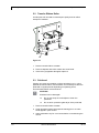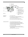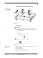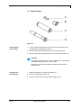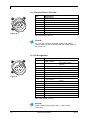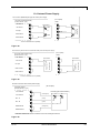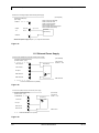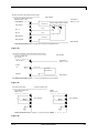
1
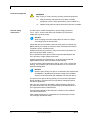
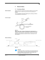
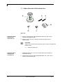
DYNACODE IP Ingress Protection Version Service Instructions Copyright by Carl Valentin GmbH / 7957125.0214 Information on the scope of delivery, appearance, performance, dimensions and weight reflect our knowledge at the time of printing. We reserve the rights to make modifications. All rights, including those regarding the translation, are reserved. No part of this document may be reproduced in any form (print, photocopy or any other method) or edited, copied or distributed electronically without written permission from Carl Valentin GmbH. Due to the constant further development of our devices discrepancies between manual and device can occur. Please check www.carl-valentin.de for the latest update. Trademarks All named brands or trademarks are registered brands or registered trademarks of their respective owners and may not be separately labelled. It must not be concluded from the missing labelling that it is not a registered brand or a registered trademark. Carl Valentin direct print modules comply with the following safety guidelines: EG Machinery Directive (2006/42/EG) CE EG Low-Voltage Directive (2006/95/EG) EG Electromagnetic Compatibility Directive (2004/108/EG) Carl Valentin GmbH Postfach 3744 78026 Villingen-Schwenningen Neckarstraße 78 – 86 u. 94 78056 Villingen-Schwenningen Phone Fax +49 (0)7720 9712-0 +49 (0)7720 9712-9901 E-Mail Internet [email protected] www.carl-valentin.de Dynacode IP Series Table of Contents Table of Contents Table of Contents ............................................................................. 3 1 Notes on this Document ....................................................... 5 1.1 User Notes............................................................................... 5 1.2 Instructions .............................................................................. 5 1.3 Cross References .................................................................... 6 2 Safety Instructions ................................................................ 7 2.1 General Safety Instructions ..................................................... 7 2.2 Safety Handling when Working with Electricity ....................... 9 2.3 Environmentally-Friendly Disposal ........................................ 10 3 General Notes ...................................................................... 11 3.1 Continuous Mode .................................................................. 11 3.2 Intermittent Mode................................................................... 12 3.3 Changing the Module Type ................................................... 13 4 Electronics (Replacing Parts) ............................................ 15 4.1 Primary Fuses ....................................................................... 15 4.2 CPU PCB............................................................................... 16 4.3 Battery ................................................................................... 17 4.4 Input/Output Board ................................................................ 17 4.5 Power Supply Unit ................................................................. 19 4.6 CF Card Slot .......................................................................... 20 4.7 Display PCB .......................................................................... 21 5 Cleaning ............................................................................... 23 5.1 Cleaning Instructions ............................................................. 23 5.2 Transfer Ribbon Roller .......................................................... 24 5.3 Printhead ............................................................................... 24 6 Printhead .............................................................................. 25 6.1 Replacing the Printhead ........................................................ 25 6.2 Angle Adjustment .................................................................. 26 7 Ribbon Cassette (Replacing Parts) ................................... 27 7.1 Track Roller ........................................................................... 27 7.2 Return Pulley ......................................................................... 29 7.3 Ribbon Rewinder Roll/Unwinder Roll .................................... 30 8 Printing Carriage (Replacing Parts)................................... 31 8.1 Printhead Fastener, Pressure Bail, Interlayer ....................... 32 8.2 Guiding Carriage ................................................................... 33 8.3 Motor Circuit Board................................................................ 34 9 Print Mechanics (Replacing Parts) .................................... 35 9.1 Pneumatic Valve.................................................................... 35 9.2 Pressure Switch..................................................................... 36 9.3 Encoder ................................................................................. 37 9.4 Limit Switch ........................................................................... 38 9.5 Cassette Switch ..................................................................... 39 9.6 LEDs ...................................................................................... 40 10 Error correction ................................................................... 41 11 Inputs and Outputs.............................................................. 51 11.1 Alarm Output ......................................................................... 51 11.2 Product Sensor / Encoder ..................................................... 52 11.3 I/O Assignment ...................................................................... 52 11.4 Internal Power Supply ........................................................... 53 11.5 External Power Supply .......................................................... 54 02.14 Service Instructions 3 Table of Contents Dynacode IP Series 12 12.1 12.2 12.3 12.4 13 13.1 13.2 13.3 13.4 13.5 14 15 4 Wiring Plans ......................................................................... 57 Control Unit............................................................................ 57 Print Mechanics Dynacode IP53 ........................................... 58 Print Mechanics Dynacode IP107 ......................................... 59 Print Mechanics Dynacode IP128 ......................................... 60 Layout Diagrams ................................................................. 61 CPU ....................................................................................... 61 Power Electronics .................................................................. 62 CF Card Slot .......................................................................... 63 Dispenser I/O......................................................................... 64 Motor Plate ............................................................................ 65 Connector Assignment of Control Unit............................. 67 Index ..................................................................................... 69 Service Instructions 02.14 Dynacode IP Series Notes on this Document 1 Notes on this Document 1.1 User Notes This service manual is intended for qualified service and maintenance staff. This manual contains information about hardware and mechanical part of the direct print module. Information about operation of the direct print module can be taken from our operating manual. If a problem arises that cannot be solved with help of this service instructions, then please contact your responsible dealer. 1.2 Instructions Basic information and warning references with the corresponding signal words for the danger level are as follows specified in this manual: DANGER identifies an extraordinarily great and immediate danger which could lead to serious injury or even death. WARNING identifies a possible danger would could lead to serious bodily injury or even death if sufficient precautions are not taken. CAUTION indicates a potentially dangerous situation which could lead to moderate or light bodily injury or damage to property. NOTICE gives you tips. They make a working sequence easier or draw attention to important working processes. Gives you tips on protecting the environment. 02.14 Handling instruction Optional accessories, special fittings Datum Information in the display Service Instructions 5 Notes on this Document Dynacode IP Series 1.3 Cross References Item numbers References to specific items in a figure are marked with item numbers. They are identified with parentheses in the text, e.g. (9). If no figure number is provided, item numbers in the text always refer to the graphic directly above the text. If a reference is made to another graphic, the figure number is specified, e.g. (2, in figure 5). Cross references to chapters and sections For a cross reference to chapters and sections, the chapter number and page number are specified, e.g. a reference to this section: see chapter 1.3.2, on page 35). References to other documents References to other documents have the following form: See 'operating manual'. 6 Service Instructions 02.14 Dynacode IP Series Safety Instructions 2 Safety Instructions 2.1 General Safety Instructions Workplace and method of working Clothing Keep the area around the device clean during and after maintenance. Work in a safety-conscious manner. Store dismantled device parts in a safe place while maintenance is being performed. CAUTION! The drawing in of items of clothing by moving parts can lead to injuries. If possible, do not wear clothing which could be caught by moving device parts. Button or roll up shirt or jacket sleeves. Tie or pin up long hair. Tuck the ends of scarves, ties and shawls into your clothing or secure them with non-conductive clips. DANGER! Risk of death from increased flow of current via metals parts which come into contact with the device. Protective clothing 02.14 Do not wear clothing with metal parts. Do not wear jewellery. Do not wear glasses with a metal frame. If a possible danger to your eyes is present, wear protective goggles, especially in the following cases: when knocking in or knocking out pins and similar parts with a hammer when using an electric drill when using spring hooks when loosening or inserting springs, snap rings and gripping rings when soldering when using solvents, cleaning agents or other chemicals Service Instructions 7 Safety Instructions Protective equipment Dynacode IP Series WARNING! Risk of injury in case of missing or faulty protective equipment. General safety instructions After performing maintenance work, attach all safety equipment (covers, safety precautions, ground cables etc.). Replace faulty parts and those which have become unusable. The direct print module is designed for power supply systems of 110 V - 230 V. Connect the direct print module only to electrical outlets with a ground contact. NOTICE! When changing the mains voltage the fuse value is to adapt accordingly (see 'Technical Data'). Couple the direct print module to devices using extra low voltage only. Before making or undoing connections, switch off all devices involved (computer, printer, accessories etc.). Operate the direct print module in a dry environment only and do not get it wet (sprayed water, mist etc.). Do not operate the direct print module in explosive atmosphere and not in proximity of high voltage power lines. Operate the direct print module only in an environment protected against abrasive dust, swarf and other similar impurity. In case of cleaning and maintenance with an open cover, ensure that clothing, hair, jewellery and similar personal items do not contact the exposed rotating parts. NOTICE! With the open printing unit (due to construction) the requirements of EN60950-1 regarding fire protection casing are not fulfilled. These must be ensured by the installation into the end device. The print unit can get hot during printing. Do not touch the printhead during operation. Cool down the print unit before changing material, removal or adjustment. Carry out only the actions described in these operating instructions. Any work beyond this may only be performed by the manufacturer or upon agreement with the manufacturer. Unauthorized interference with electronic modules or their software can cause malfunctions. Other unauthorized work or modifications to the direct print module can endanger operational safety. 8 Service Instructions 02.14 Safety Instructions Dynacode IP Series Always have service work done in a qualified workshop, where the personnel have the technical knowledge and tools required to do the necessary work. There are warning stickers on the direct print modules that draw your attention to dangers. Therefore the warning stickers are not to be removed as then you and others cannot be aware of dangers and may be injured. The direct printing unit must be integrated with the Emergency Stop circuit when it is incorporated into the overall machine. All isolating safety equipment must be installed before starting-up the machine. DANGER! Danger to life and limb from power supply! Do not open the casing. 2.2 Safety Handling when Working with Electricity Qualifications of personnel General precautions to be heeded when beginning maintenance 02.14 The following work may only be performed by instructed and trained electricians: work on the electrical assemblies work on the device while it is open and connected to the power supply. Locate the emergency-stop or power switch so that it can be actuated in case of an emergency. Unplug the device from the electrical outlet before performing the following work: removing or installing power supply units working in the immediate vicinity of exposed power supply parts mechanical inspection of power supply parts modifying the device circuits. Ensure that the device is de-energized. Check the workplace for possible sources of danger, e.g. moist floors, defective extension cables, faulty protective conduction connections. Service Instructions 9 Safety Instructions Additional precautions to be heeded for devices with exposed energized parts Dynacode IP Series Tools What to do in case an accident occurs Give another person the task of remaining near the workplace. This person must be familiar with the location and operation of the emergency-stop and power switches and switch off the power if danger arises. Use only one hand while working on electrical circuits when a device is switched on. Hold the other hand behind your back or put it in your jacket pocket. This prevents the electricity from flowing through your body. To not use worn or damaged tools. Use only tools and testing equipment that is suitable for the respective task. Proceed in a very cautions and calm manner. Avoid endangering yourself. Switch the power off. Request medical help (emergency physician). Call for first aid if necessary. 2.3 Environmentally-Friendly Disposal Manufacturers of B2B equipment are obliged to take back and dispose of old equipment that was manufactured after 13 August 2005. As a principle, this old equipment may not be delivered to communal collecting points. It may only be organised, used and disposed of by the manufacturer. Valentin products accordingly labelled can therefore be returned to Carl Valentin GmbH. This way, you can be sure your old equipment will be disposed of correctly. Carl Valentin GmbH thereby fulfils all obligations regarding timely disposal of old equipment and facilitates the smooth reselling of these products. Please understand that we can only take back equipment that is sent free of carriage charges. Further information on the WEEE directive is available on our website www.carl-valentin.de. 10 Service Instructions 02.14 Dynacode IP Series General Notes 3 General Notes 3.1 Continuous Mode Material Speed Please note that the material has sufficient adhesion at the pressure transducer roll or encoder roll to permit the exact speed by the encoder. It is only possible to print when respecting the operating conditions, i.e. the speed has to be observed. Print Principle Figure 1 After starting a print order the printhead moves against the print medium. The feed of material is registered by the encoder and then evaluated. The printhead is in start position as long as the printing onto the moving material is finished and then it moves back to its home position. Material Guiding Figure 2 NOTICE! In case the encoder is connected to the counter-pressure roll or the encoder roll you have to observe that the material has sufficient adhesion at the pressure roll or encoder roll to guarantee an exact speed by the encoder. 02.14 Service Instructions 11 General Notes Dynacode IP Series 3.2 Intermittent Mode Print Principle Lift Printhead Feed Packaging material Print surface Figure 3 After starting a print order the printhead moves against the print medium. Afterwards the printing carriage moves corresponding to the set or transferred layout length linear over the material which is to be printed. After the print procedure the printhead again lifts up and the printing carriage moves again to the starting position. Print position NOTICE! The direct print module is delivered with a default print length of 65 mm. In order to use the maximum print length of 75 mm, the print position value must be changed to 93. Figure 4 A: Print pos. / Start pos. value = 93 B: Print pos. / Start pos. value = 83 C: Max. position print end D: Stand-by position 12 Service Instructions 02.14 General Notes Dynacode IP Series 3.3 Changing the Module Type Switch on the control unit and the display shows the main menu. Press key to access the function menu. Press key as long as you arrive the Service functions menu. Press key to select the menu. Press key as long as you arrive at the menu Paper counter. Press key to access the menu Password. Enter the service password '2904'. to confirm the entry. Press key Press key or to select the module type. to confirm the selection. Press key The changed module type is indicated in the display. to arrive the next display. Press key Indication if a standard motor (ID166) or a stronger motor (ID267) is installed. Press key Press key mounted. 02.14 to arrive at the next display. or to select if a left or a right print module is Service Instructions 13 Dynacode IP Series Electronics (Replacing Parts) 4 Electronics (Replacing Parts) DANGER! Risk of death via electric shock! Before opening the housing cover, disconnect the device from the mains supply and wait approx. 2 - 3 minutes until the power supply unit has discharged. 4.1 Primary Fuses A Figure 5 1. Unplug the control unit from the electrical outlet 2. Open the housing with the attached key. 3. Unscrew the fuse-holder (A) counter clockwise. 4. Replace the fuses (microfuse 2.0 AT). 5. If necessary, replace the fuse in the second fuse-holder. 6. Close the housing of the printing sytsem. 02.14 Service Instructions 15 Electronics (Replacing Parts) Dynacode IP Series A A A 4.2 CPU PCB B C A A A Figure 6 Removing the CPU PCB Installing the CPU PCB 16 NOTICE! Save the configuration of direct print module onto a CF card. 1. 2. 3. 4. 5. Unplug the control unit from the electrical outlet. Open the housing with the attached key. Unplug all connections from the CPU PCB (B). Remove all screws (A) from the CPU PCB. Remove the CPU BCP (B) carefully. 1. 2. 3. 4. 5. Install the CPU PCB to the existing bolts. Fix the CPU PCB with screws (A). Connect again the power cable. Verify firmware version and update it, if necessary. Load the configuration of the direct print module from CF card. Otherwise set the configuration with help from the function menu. Service Instructions 02.14 Dynacode IP Series Electronics (Replacing Parts) 4.3 Battery DANGER! Danger of explosion when exchanging the battery improper! Pay attention to polarity. 1. Lift up the fixing bracket by means of a non-metallic device (e.g. plastic ruler). 2. Remove the defective battery (A). 3. Instert a new battery into the support (C, Figure 6). NOTICE! Pay attention to polarity. 4.4 Input/Output Board NOTICE! The inputs/outputs can be tested in the Service Functions. If an input is activated then the position corresponding to this input changes to 1. To activate an output, move the cursor to the corresponding position and press the keys and to set value 1. To deactivate the output, set the corresponding position again to 0. Inputs and outputs marked with 'x' are not occupied (example at the left side). The example refers to the I/O Profile 'standard_direct' (see function menu I/O Parameters). 02.14 Service Instructions 17 Electronics (Replacing Parts) Dynacode IP Series A B Figure 7 C C C C Figure 8 Removing the I/O board 1. Unplug the control unit from the electrical outlet 2. Open the housing with the attached key. 3. Remove CPU PCB (see chapter 4.2, page 16). 4. Remove all connections from I/O interface (A). 5. Remove hexagonal bolts (B). 6. Remove screws (C). 7. Remove the I/O board. Installing the I/O board 1. Install the new I/O board. 2. Install the screws (C). 3. Install the hexagonal bolts (B). 4. Insert again all connections. 5. Install again the CPU PCB. 6. Close the housing of control unit. 7. Connect again the power cable. 18 Service Instructions 02.14 Dynacode IP Series Electronics (Replacing Parts) 4.5 Power Supply Unit A B C Figure 9 Removing the power supply unit Figure 10 Figure 11 1. Unplug the control unit from the electrical outlet. 2. Open the housing with the attached key. 3. Loosen screws (A) of power supply unit (B) at the electronics underside. At the same time hold power supply unit. 4. Put the power unit next to the control unit. 5. Remove transparent cover above the clamps (C). 6. Loosen clamps (C) and remove all connections. Installing the power supply unit 1. Fix again all connections at the clampsl (C) of the new power unit. NOTICE! Pay attention to the correct cable configuration at the screwtype terminal. 2. Apply the transparent cover above the clamps. 3. Place the new power unit in the control unit and fix it with the screws (A). 4. Close the housing of control unit. 5. Connect again the power cable. 02.14 Service Instructions 19 Electronics (Replacing Parts) Dynacode IP Series 4.6 CF Card Slot A B A Figure 12 Removing the CF card slot 1. Unplug the control unit from the electrical outlet 2. Open the housing with the attached key. 3. Unplug the connecting cable from CPU PCB to the slot (B). 4. Remove hexagonal nuts (A). 5. Remove the defective slot. Installing the CF card slot 1. Insert the new CF card slot. 2. Install hexagonal nuts (A). 3. Insert connection cable from CPU PCB to slot (B). 4. Close the housing of control unit. 5. Connect again the power cable. 20 Service Instructions 02.14 Dynacode IP Series Electronics (Replacing Parts) 4.7 Display PCB A B A Figure 13 Removing the display PCB 1. Unplug the control unit from the electrical outlet. 2. Open the housing with the attached key. 3. Unplug the connecting cable from CPU PCB to display PCB (B). 4. Remove hexagonal nuts (A). 5. Remove defective display PCB. Installing the display PCB 1. Insert the new display PCB. 2. Install hexagonal nuts (A). 3. Insert connection cable from CPU PCB to display PCB (B). 4. Close the housing of control unit. 5. Connect again the power cable. 02.14 Service Instructions 21 Dynacode IP Series Cleaning 5 Cleaning DANGER! Risk of death via electric shock! Before opening the housing cover, disconnect the device from the mains supply and wait approx. 2 - 3 minutes until the power supply unit has discharged. NOTICE! When cleaning the label printer, personal protective equipment such as safety goggles and gloves are recommended. 5.1 Cleaning Instructions NOTICE! The handling instructions for the use of Isopropanol (IPA) must be observed. In the case of skin or eye contact, immediately wash off the fluid thoroughly with running water. If the irritation persists, consult a doctor. Ensure good ventilation. CAUTION! Abrasive cleaning agents can damage the direct print module! Do not use abrasives or solvents to clean the outer surface of the direct print module. 1. Remove dust and paper fuzz in the printing area with a soft brush or vacuum cleaner. 2. Clean outer surfaces with an all-purpose cleaner. 02.14 Service Instructions 23 Cleaning Dynacode IP Series 5.2 Transfer Ribbon Roller A soiled print roll can lead to reduced print quality and can affect transport of material. A Figure 14 1. Remove transfer ribbon cassette. 2. Remove deposits with roller cleaner and a soft cloth. 3. If the roller (A) appears damaged, replace it. 5.3 Printhead Printing can cause accumulation of dirt at printhead e.g. by colour particles of transfer ribbon, and therefore it is necessary to clean the printhead in regular periods depending on operating hours, environmental effects such as dust etc. CAUTION! Printhead can be damaged! Do not use sharp or hard objects to clean the printhead. Do not touch protective glass layer of the printhead. 1. Remove transfer ribbon cassette. 2. Clean printhead surface with special cleaning pen or a cotton swab dipped in pure alcohol. 3. Allow printhead to dry for 2-3 minutes before commissioning the device. 24 Service Instructions 02.14 Dynacode IP Series Printhead 6 Printhead 6.1 Replacing the Printhead D C CAUTION! The printhead can be damaged by static electricity discharges and impacts! B A Figure 15 Removing the printhead Set up the device on a grounded, conductive surface. Ground your body, e.g. by wearing a grounded wristband. Do not touch contacts on the plug connections. Do not touch the printhead with hard objects or your hands. 1. Remove ribbon cassette. 2. Move printhead unit in an appropriate service position. 3. Press printhead support (C) slightly downwards until an Allen key (2.5) can be inserted in the screws (A). 4. Remove screws (A) and afterwards the printhead (B). 5. Remove rear-mounted connection assembly from printhead Installing the printhead 1. Insert connection assembly to the new printhead. 2. Position printhead in printhead support (C), so the engaging pieces catch in the appropriate holes in the printhead (B). 3. Hold printhead holder (C) with a finger slightly on the pressure roll and check the correct position of printhead (B). 4. Screw in screw (A) and tighten it with an Allen key. 5. Insert again ribbon cassette. 6. Enter the resistance value of the new printhead in the menu Service Functions/Heater resistance. The value is indicated on the type plate of printhead. 7. Start a test print to check printhead position. 02.14 Service Instructions 25 Printhead Dynacode IP Series 6.2 Angle Adjustment Figure 16 The installation angle of the printhead is default 26° to the print surface. However, manufacturing tolerances of printhead and mechanics can require another angle. CAUTION! Damage of printhead by unequal use! Higher wastage of ribbon by faster ripping. Change factory settings only in exceptional cases. 1. Loosen slightly two Allen head screws (A). 2. Move adjusting part (B) to adjust the angle between printhead and printhead support. move downwards = decrease angle move upwards = increase angle 3. Tighten again the Allen head screws (A). 4. Start a print order with approx. 3 layouts to check the correct unwrinkled ribbon run. NOTICE! The slots (C) serve for position control. Pay attention to a parallel adjustment. 26 intermittend mode Service Instructions 02.14 Dynacode IP Series Ribbon Cassette (Replacing Parts) 7 Ribbon Cassette (Replacing Parts) View of transfer ribbon cassette Figure 17 7.1 Track Roller NOTICE! The track roller can be removed without previous loosening of the switch roll. Use a screw driver with max. diameter 5 mm and remove the screw (B). A B C Figure 18 Removing the roller 1. Remove switch roll (C) from track roller (A). Use a 5 Cent coin or a similar auxiliaries. 2. Remove the screw (B). 3. Remove pillar from the track roller (A). 02.14 Service Instructions 27 Ribbon Cassette (Replacing Parts) Dynacode IP Series NOTICE! The sliding supports of track roller are destined for unlubricated operation and therefore are not to be oiled. However, a one-time lubrication at installation improves the infeed manner. Installing the track roller 1. Install track roller (A) to the pillar. 2. Tighten the screw (B). 3. Install switch roll (C) to the track roller (A). NOTICE! Use screw locking adhesive Loctite® 243™ to secure screw (B) against unintentional unscrewing. 28 Service Instructions 02.14 Dynacode IP Series Ribbon Cassette (Replacing Parts) 7.2 Return Pulley A B C D Figure 19 Removing the return pulley 1. Loosen 3 Allen head screws on the inside and remove the rod at the side with the handhold (cassette). 2. Unscrew the Allen head screw (A) of the corresponding roll. 3. Remove bushing for centring sleeve (B + D) and return pulley (C). NOTICE! The sliding supports of track roller are destined for unlubricated operation and therefore are not to be oiled. However, a one-time lubrication at installation improves the infeed manner. Installing the return pulley 1. Install bushings (B + D) and return pulley (C). 2. Screw the socket head screw (A). 3. Tighten 3 Allen head screws and install again the rod. 02.14 Service Instructions 29 Ribbon Cassette (Replacing Parts) Dynacode IP Series 7.3 Ribbon Rewinder Roll/Unwinder Roll A A E B C D Figure 20 Removing ribbon rewinder roll /unwinder roll 1. Remove screw (D) from the appropriate ribbon roll. Take care to hold the centring sleeve (B). 2. Remove chuck cone (C), centring sleeve (B), springs (A) and ribbon roll (E). CAUTION! Using of oil in the environmnet of the chuck cone (C) can affect the brake function. Installing ribbon rewinder roll/ unwinder roll 30 Clean the brake cone. 1. Install again the chuck cone (C), centring sleeve (B), springs (A) and ribbon roll (E). 2. Tighten the screws (D) of the appropriate ribbon roll. Take care to hold the centring sleeve (B). Service Instructions 02.14 Dynacode IP Series Printing Carriage (Replacing Parts) 8 Printing Carriage (Replacing Parts) View of printing carriage F G H F Figure 21 C E D B A Figure 22 C B C Figure 23 02.14 Service Instructions 31 Printing Carriage (Replacing Parts) Dynacode IP Series 8.1 Printhead Fastener, Pressure Bail, Interlayer S S G F C F D C R R Figure 24 1. Remove transfer ribbon cassette. 2. Push both tension springs (C, Figure 23) with tweezers from the pillars (B, Figure 23). 3. Remove printhead cable (E, Figure 22) from printhead (A, Figure 22). 4. Remove Allen head screws (G, Figure 21). 5. Remove the complete printhead unit (printhead fastener, pressure bail, interlayer). 6. Start the necessary service work, e.g. replacing springs (C) or printhead fastener. Please read the following notice. NOTICE! The component can be decomposed in more individual parts. Unscrew the pillars (F) and remove the printhead shaft (D). At installation take care of parallelism of slots next to the screws (G) to the slots in the guiding carriage (H, Figure 21). NOTICE! Use screw locking adhesive Loctite® 243™ to secure pillars (F) and screws (R + S) against unintentional unscrewing. 32 Service Instructions 02.14 Dynacode IP Series Printing Carriage (Replacing Parts) 8.2 Guiding Carriage HI J P O N M L K Figure 25 1. Replacing pneumatic cylinder For replacing the pneumatic cylinder (L), remove the Allan head screws (M) and then remove the pneumatic tube. 2. Replacing linear guiding For replacing the linear guiding (O), remove the Allan head screws (N). Push the guiding carriage (H) aside until the track carriage underneath appears. For replacing the linear guiding (O), remove the Allen head screws (P). The guiding has only little play in the nut to guarantee a linear guiding. Lever the linear guiding by means of a screw driver carefully. NOTICE! If the new guiding should have too much play in the nut, press it to the edge and tighten it. 3. Replacing guiding roll For replacing the guiding roll (I), remove the Allan head screw (K). 4. Replacing guiding carriage For replacing the guiding carriage (H), push the carriage over drillings (J). Insert allen key 2,5 from the botton through the drillings (J) in the screws of the clamping sheet (not visible). Remove 4 screws (N) and remove guiding carriage (H). NOTICE! Use screw locking adhesive Loctite® 243™ to secure screws (I) of the washer lock (J) against unintentional unscrewing. 02.14 Service Instructions 33 Printing Carriage (Replacing Parts) Dynacode IP Series 8.3 Motor Circuit Board A B Figure 26 Removing motor circuit board 1. Remove connecting cable between control unit and print mechanics. 2. Loosen the side screws and remove the mechanics housing at the rear. 3. Remove all connections at the motor circuit board. 4. Remove screws (A). 5. Remove hexagonal bolt (B) at the plug connectors. 6. Remove motor circuit board. Installing motor circuit board 1. Insert a new motor circuit board. 2. Insert the hexagonal bolt (B) at the plug connectors. 3. Tighten the screws (A). 4. Insert all connections to the motor circuit board. 5. Tighten the side screws and fix the mechanics housing at the rear. 6. Insert the connecting cable between control unit and print mechanics. NOTICE! Use screw locking adhesive Loctite® 243™ to secure hexagon bolts (B) against unintentional unscrewing. 34 Service Instructions 02.14 Dynacode IP Series Print Mechanics (Replacing Parts) 9 Print Mechanics (Replacing Parts) 9.1 Pneumatic Valve DANGER! Danger of injury by causing a short-circuit. Because of technical reasons, the adjusting screw of pressure control device unit is on a tension potential of 5V. Do not touch components connected with mass. I H G F E Removing the pneumatic valve D C B A Figure 27 Use isolated tools. Figure 28 1. Loosen the side screws and remove the mechanics housing at the rear. 2. Loosen screws (A, C, and G). 3. Loosen tube (E) from plug-in connection of pneumatic valve (B) 4. Remove pressure switch unit outwards. 5. Loosen tube item (Ø 4 mm) at the bottom side of valve (not visible) and remove the pneumatic valve. 6. Loosen screw (D) and remove pneumatic valve from aluminium fastener. Installing the pneumatic valve 1. Install the new pneumatic valve with screw (D) at the aluminium fastener. 2. Insert tube item at the bottom side of valve. 3. Install pressure switch unit. 4. Fix tube item (E) at the plug-in connection of pneumatic valve (B). 5. Tighten screws (A, C, and G). 6. Tighten the side screws and fix the mechanics housing at the rear. 02.14 Service Instructions 35 Print Mechanics (Replacing Parts) Dynacode IP Series 9.2 Pressure Switch DANGER! Danger of injury by causing a short-circuit. Because of technical reasons, the adjusting screw of pressure control device unit is on a tension potential of 5V. Removing the pressure switch Use isolated tools. Do not touch components connected with mass. 1. Loosen the side screws and remove the mechanics housing at the rear. 2. Remove screws (A, C, and G). 3. Loosen tube (E) from plug-in connection of pneumatic valve (B). 4. Remove pressure switch unit outwards. 5. Remove screw in union (F) with all gaskets and then unplug the flat plug (I). 6. Remove the pressure switch (H). Installing the pressure switch 1. Install the new pressure switch. 2. Insert the flat plug (I) and fix the screw in union (F) with all gaskets. 3. Install the pressure switch unit. 4. Fix tube item (E) at the plug-in connection of pneumatic valve (B). 5. Tighten screws (A, C, and G). 6. Tighten the side screws and fix the mechanics housing at the rear. NOTICE! At the new pressure switch you have to set the switch-point. For this procedure, the compressed air supply is set to 2 bars at manometer. In the Service Functions menu the value 'P' for compressed-air control is examined. Turn at the adjusting thread of pressure switch (between flat connections!) until the value changes from 0 to 1. If you set at manometer a value smaller 2 bar, then value 'P' must be again set to 0. Adjust finely again if necessary. 36 Service Instructions 02.14 Dynacode IP Series Print Mechanics (Replacing Parts) 9.3 Encoder A DE D B C F Figure 29 Removing the encoder Figure 30 1. Remove connecting cable between control unit and print mechanics. 2. Loosen the side screws and remove the mechanics housing at the rear. 3. Remove hexagon bolt at the plugs (see chapter 8.3, page 34). 4. Remove screws (A + F) and the screw at the valve holder (see chapter 9.1, page 35). 5. Remove connection plate (B). 6. Unplug connector assembly (E). 7. Press the engagement hook (D) of the encoder (C) inwards and push the encoder forwards on the aluminium plate. Installing the encoder 1. Push the encoder into the aluminium plate and take care that the engagement hooks (D) engage. 2. Insert connector assembly (E). 3. Install the connection plate. 4. Tighten screws (A + F) and screw at the valve holder. 5. Insert hexagonal bolt at the plugs. 6. Tighten the side screws and fix the mechanics housing at the rear. 7. Insert the connecting cable between control unit and print mechanics. 02.14 Service Instructions 37 Print Mechanics (Replacing Parts) Dynacode IP Series 9.4 Limit Switch D C B x 8 A ︵ ︶ E E Figure 31 Removing the limit switch 1. Loosen the side screws and remove the mechanics housing at the rear. 2. Remove the screws (A) of cover plate (B). The limit switches (E) are on the bottom side of aluminium plate. 3. Loosen the screws of the limit switch. 4. Trace the connecting lines and remove them from the motor plate. 5. Remove the limit switch. Installing the limit switch 1. Install the new limit switch. 2. Insert the connecting lines at the motor plate. 3. Tighten the screws of limit switch. 4. Tighten the screws (A) of cover plate (B). 5. Tighten the side screws and fix the mechanics housing at the rear. NOTICE! Finally the switching of limit switch is to be examined. Push the printing carriage by hand towards the switch. The limit switch is to be operated before the printing carriage pushes towards the stop. 38 Service Instructions 02.14 Dynacode IP Series Print Mechanics (Replacing Parts) 9.5 Cassette Switch D C B x 8 A ︵ ︶ E E Figure 32 Removing the cassette switch 1. Loosen the side screws and remove the mechanics housing at the rear. 2. Remove the screws (A) of cover plate (B). The cassette switch (C) is visible after removing the cover plate (B). 3. Loosen the screws of the cassette switch. 4. Trace the connecting lines and remove them from the motor plate. 5. Remove the cassette switch. Installing the cassette switch 1. Install the new cassette switch. 2. Insert the connecting lines at the motor plate. 3. Tighten the screws of cassette switch. 4. Tighten the screws (A) of cover plate (B). 5. Tighten the side screws and fix the mechanics housing at the rear. NOTICE! Finally the switching of cassette switch is to be examined. This is a Reed switch, i.e. the magnet at the front cover plate releases the switch. 02.14 Service Instructions 39 Print Mechanics (Replacing Parts) Dynacode IP Series 9.6 LEDs D C B x 8 A ︵ ︶ E E Figure 33 Removing the LEDs 1. Loosen the side screws and remove the mechanics housing at the rear. 2. Remove the screws (A) of cover plate (B). The LEDs (D) are visible after removing the cover plate (B). 3. Trace the connecting lines and remove them from the motor plate. 4. Press the LED support (D) to the front from the drilling hole in the aluminium plate. 5. Press out backwards the LED (D) from the support. Installing the LEDs 1. Press new LEDs in the support. 2. Push the LED support backwards to the drilling holes in the aluminium plate. 3. Insert the connecting lines at the motor plate. 4. Tighten the screws (A) of cover plate (B). 5. Tighten the side screws and fix the mechanics housing at the rear. 40 Service Instructions 02.14 Dynacode IP Series Error correction 10 Error correction Error message Cause Remedy 1 Line rises up completely or partly over the upper edge of label. Move line down (increase Y value). Line rises up completely or partly over the bottom edge of label. Move line up (reduce X value). One res. several characters of the text is res. are not available in the selected font. Change text. 2 3 Line too high Line too low Character set Check rotation and font. Check rotation and font. Change font. 4 Unknown code type Selected code is not available. Check code type. 5 Unvalid position Selected position is not available. Check position. 6 CV font Selected font is not available. Check font. 7 Vector font Selected font is not available. Check font. 8 Measuring label While measuring no label was found. Check label length and if labels are inserted correctly. Set label length is too large. Restart measuring anew. No label available. Insert new label roll. Soiled label photocell. Check if labels are inserted correctly. 9 No label found Labels not inserted correctly. Clean the label photocell. 10 No ribbon During the print order the ribbon roll becomes empty. Defect at the transfer ribbon photocell. 11 COM FRAMING Stop bit error. Change transfer ribbon. Check transfer ribbon photocell (service functions). Check stop bits. Check baud rate. Check cable (printer and PC). 12 COM PARITY Parity error. Check parity. Check baud rate. Check cable (printer and PC). 02.14 Service Instructions 41 Error correction Dynacode IP Series Error message Cause Remedy 13 Loss of data at serial interface (RS-232). Check baud rate. Received line number is invalid at RS-232 and Centronics. Check sent data. Invalid length of received mask statement. Check sent data. Transferred mask statement is invalid. Check sent data. No end of data found. Check sent data. 14 15 16 17 COM OVERRUN Field numer Length mask Unknown mask Missing ETB Check cable (printer and PC). Check connection PC - printer. Check connection PC - printer. Check connection PC - printer. Check connection PC - printer. 18 19 20 Invalid character Invalid statement Invalid check digit One res. several characters of the text is res. are not available in the selected font. Change text. Unknown transferred data record. Check sent data. For check digit control the entered res. received check digit is wrong. Calculate check digit anew. Change font. Check connection PC - printer. Check code data. 21 Invalid SC number Selected SC factor is invalid for EAN res. UPC. Check SC factor. 22 Invalid number of digits Entered digits for EAN res. UPC are invalid Check number of digits. < 12; > 13. 23 Check digit calculation Selected check digit calculation is not available in the bar code. Check calculation of check digit. Check bar code type. 24 Invalid extension Selected zoom factor is not available. Check zoom factor. 25 Offset sign Entered sign is not available. Check offset value. 26 Offset value Entered offset value is invalid. Check offset value. 42 Service Instructions 02.14 Dynacode IP Series Error correction Error message Cause Remedy 27 Printhead temperature is too high. Reduce contrast. Printhead temperature Change printhead. Defective printhead sensing device. 28 Cutter error With cut an error occurred. Check label run. Paper jam. Check cutter run. 29 Invalid parameter Entered data do not correspond to the characters allowed from the application identifier. Check code data. 30 Application Identifier Selected application identifier is not available in GS1-128. Check code data. 31 HIBC definition F Missing HIBC system sign. Check definition of HIBC code. Missing primary code. 32 System clock Real Time Clock function is selected but the battery is empty. Change battery. Change RTC component. Defective RTC. 33 No CF interface Interrupted connection CPU CF card. Check connection CPU - CF card interface. Defective CF card interface. Check CF card interface. 34 No print memory No print CF found. Check CF assembly on CPU. 35 Cover open At start of a print order the printhead is open. Close the printhead and start print order anew. 36 BCD invalid format BCD error Check entered format. Invalid format for the calculation of Euro variable. 37 BCD overflow BCD error Check entered format. Invalid format for the calculation of Euro variable. 38 BCD division BCD error Check entered format. Invalid format for the calculation of Euro variable. 39 FLASH ERROR Flash component error. Run a software update. Change CPU. 02.14 Service Instructions 43 Error correction Dynacode IP Series Error message Cause Remedy 40 Invalid length of the received command statement. Check data sent. Length command Check connection PC - printer. 41 No drive CF card not found / not correctly inserted. Insert CF card correctly. 42 Drive error Impossible to read CF card (faulty). Check CF card, if necessary change it. 43 Not formatted CF Card not formatted. Format CF card. 44 Delete current directory Attempt to delete the actual directory. Change directory. 45 Path too long Too long indication of path. Indicate a shorter path. 46 Drive writeprotected Memory card is write-protected. Deactivate write protection. 47 Directory not file Attempt to indicate a directory as file name. Correct your entry. 48 File already open Attempt to change a file during an access is active. Select another file. 49 No file/directory File does not exist on CF card. Check file name. 50 Invalid file name File name contains invalid characters. Correct entry of name, remove special characters. 51 Internal file error Internal file system error. Please contact your distributor. 52 Root full The max. number (64) of main directory entries is reached. Delete at least one main directory entry and create subdirectories. 53 Drive full Maximum CF capacity is reached. Use new CF Card, delete no longer required files. 54 File/directory exists The selected file/directory already exists. Check name, select a different name. 44 Service Instructions 02.14 Dynacode IP Series Error correction Error message Cause Remedy 55 File too large During copying procedure not enough memory space onto target drive available. Use a larger target card. 56 No update file Errors in update file of firmware. Start update file anew. 57 Invalid graphic file The selected file does not contain graphic data. Check file name. 58 Directory not empty Attempt to delete a not empty directory. Delete all files and subdirectories in the desired directory. 59 No interface No CF card drive found. Check connection of CF card drive. Contact your distributor 60 No CF card No CF card is inserted. Insert CF card in the slot. 61 Webserver error Error at start of web server. Please contact your distributor. 62 Wrong FPGA The direct print module is equipped with the wrong FPGA. Please contact your distributor. 63 End position The label length is too long. Check label length res. the number of labels per cycle. The number of labels per cycle is too much. 64 Zero point Defective photocell. Change photocell. 65 Compressed air Pressure air is not connected. Check pressure air. 66 External releaser External print release signal is missing. Check input signal. 67 Row too long Wrong definition of column width res. number of columns. Reduce the column width res. correct the number of columns. 68 Scanner The connected bar code scanner signals a device error. Check the connection scanner/printer. Check scanner (dirty). 02.14 Service Instructions 45 Error correction Dynacode IP Series Error message Cause Remedy 69 Bad print quality. Increase contrast. Printhead completely soiled or defective. Clean printhead or exchange (if necessary). Print speed too high. Reduce print speed. Scanner NoRead 70 Scanner data Scanned data does not correspond to the data which is to print. Exchange printhead. 71 Invalid page As page number either 0 or a number > 9 is selected. Select a number between 1 and 9. 72 Page selection A page which is not available is selected. Check the defined pages. 73 Page not defined The page is not defined. Check the print definition. 74 Format user guiding Wrong format for customised entry. Check the format string. 75 Format date/time Wrong format for date/time. Check the format string. 76 Hotstart CF No CF card found. If option hotstart was activated, a CF card must be inserted. Switch off the printer before inserting the memory card. 77 Flip/Rotate Selection of print of several columns and also mirror/rotate. It is only possible to select one of both functions. 78 System file Loading of temporary hotstart files. Not possible. 79 Shift variable Faulty definition of shift times Check definition of shift times. (overlapping times). 80 GS1 Databar General GS1 Databar error. Check definition and parameter of GS1 Databar code. 81 IGP error Protocol error IGP. Check sent data. 82 Time generation Printing creation was still active at print start. Reduce print speed. Use printers' output signal for synchronisation. Use bitmap fonts to reduce generating time. 46 Service Instructions 02.14 Dynacode IP Series Error correction Error message Cause Remedy 83 Both DPM position sensors (start/end) are active. Displace zero point sensor Transport protection Check sensors in service functions menu 84 No font data Font and web data is missing. Run a software update. 85 No layout ID Label ID definition is missing. Define label ID onto the label. 86 Layout ID Scanned data does not correspond to defined ID. Wrong label loaded from CF card. 87 RFID no label RFID unit cannot recognise a label. Displace RFID unit or use an offset. 88 RFID verify Error while checking programmed data. Faulty RFID label. Error at programming the RFID label. Label positioning. 89 RFID timeout Check RFID definitions Faulty label. 90 RFID data Faulty or incomplete definition of RFID data. Check RFID data definitions. 91 RFID tag type Definition of label data does not correspond with the used label. Check storage partitioning of used label type 92 RFID lock Error at programming the RFID label (locked fields). Check RFID data definitions. Check RFID definitions. 93 RFID programming Error at programming the RFID label. 94 Scanner timeout The scanner could not read the bar code within the set timeout time. Label was already programmed. Defective printhead. Check printhead. Wrinkles in transfer ribbon. Check transfer ribbon. Scanner wrong positioned. Position scanner correctly, corresponding to the set feeding. Timeout time too short. Select longer timeout time. 02.14 Service Instructions 47 Error correction Dynacode IP Series Error message Cause Remedy 95 Scanner data does not correspond to bar code data. Check adjustment of scanner. Scanner layout difference Check scanner settings / connection. 96 COM break Serial interface error. Check settings for serial data transmission as well as cable (printer-PC). 97 COM general Serial interface error. Check settings for serial data transmission as well as cable (printer-PC). 98 No software printhead FPGA No printhead-FPGA data available. Please contact your responsible distributor. 99 Load software printhead FPGA Error when programming printhead-FPGA. Please contact your responsible distributor. 100 Upper position Sensor signal up is missing Check input signals / compressed-air supply. (option APL 100). 101 Lower position Sensor signal down is missing (option APL 100). 102 Vacuum plate empty Sensor does not recognise a label at vacuum plate Check input signals / compressed-air supply. Check input signals / compressed-air supply. (option APL 100). 103 Start signal Print order is active but device not ready to process it. Check start signal. 104 No print data Print data outside the defined label. Check selected module type. Selection of wrong module type (design software). 105 Printhead No original printhead is used. Check selection of left/right version. Check the used printhead. Contact your distributor. 106 Invalid Tag type Wrong Tag type. Tad data do not match the Tag type in the printer. 107 RFID invalid RFID module is not activated. No RFID data can be processed. 48 Service Instructions Adapt data or use the correct Tag type. Activate RFID module or remove RFID data from label data. 02.14 Dynacode IP Series Error correction Error message Cause Remedy 108 GS1-128 invalid Transferred GS1-128 bar code is invalid. Verify bar code data (see GS1128 bar code specification). 109 EPC parameter Error at EPC calculation. Verify data (see EPC specification). 110 Housing open When starting the print order the housing cover is not closed. Close the housing cover and start the print order anew. 111 EAN.UCC code Transferred EAN.UCC code is invalid. Verify bar code data (see corresponding specification). 112 Print carriage Printing carriage does not move. Check gear belt (possibly broken). 113 Applicator error Error while using applicator. Check applicator. 114 Left position Left final position switch is not in correct position. Check LEFT final position switch for correct function and position. Check function of pneumatics for cross traverse. 115 Right position Right final position switch is not in correct position. Check RIGHT final position switch for correct function and position. Check function of pneumatics for cross traverse. 116 Print position The print position is not correct. Check TOP and RIGHT final position switch for correct function and position. Check pneumatics for function 117 XML parameter The parameters in the XML file are not correct. Please contact your responsible distributor. 118 Invalid variable Transferred variable is invalid with customized entry. Select correct variable without customized entry and transfer it. 119 No ribbon During the print order the ribbon roll becomes empty. Change transfer ribbon. Defect at the transfer ribbon photocell. 120 Wrong directory Invalid target directory when copying. Check transfer ribbon photocell (service functions). Target directory must not be within the source directory. Check target directory. 02.14 Service Instructions 49 Error correction Dynacode IP Series Error message Cause Remedy 121 No label found at the rear printhead (DuoPrint). Insert new label roll. No label found Soiled label photocell. Labels not inserted correctly. Clean the label photocell. Check if labels are inserted correctly. 122 IP occupied The IP address was already assigned. Assign a new IP address. 123 Print asynchronous The label photocell do not work in the order as it is expected according to print data. Check label size and gap size. The settings of the photocell are not correct. Check label photocell settings. Settings of label size and gap size are not correct. Check correct loading of label material. No label found at the rear printhead. Insert new label roll. Soiled label photocell. Clean the label photocell. Labels not inserted correctly. Check if labels are inserted correctly. Print speed is too slow. Increase the speed of customers' machine. 124 50 Speed too slow Service Instructions 02.14 Dynacode IP Series Inputs and Outputs 11 Inputs and Outputs Figure 34 A = Alarm output (rely) B = Connection encoder and product sensor C = Connection encoder and product sensor D = External I/O 11.1 Alarm Output With the alarm output the device makes available the changeover contact of a relay, The relay can be used either as Normally Closed Contact or as Normally Open Contact. Figure 35 Pin 1 2 3 4 5 6 Description NO (normally open contact) C (centre contact) NC (normally closed contact) PE Not occupied Not occupied Load current: 1 A Contact voltage: 230 V 02.14 Service Instructions 51 Inputs and Outputs Dynacode IP Series 11.2 Product Sensor / Encoder Figure 36 Pin 1 2 3 4 5 6 7 Casing Description GND internal GND external Encoder lane A + UB external (max. 30 VDC) + UB internal (approx. 24 VDC) Input product sensor Encoder lane B Shielding Max. load current: 100 mA NOTICE! Pin 1 and Pin 2 must be bypassed if the encoder and/or product sensor should be operated with the voltage supply of the control unit. 11.3 I/O Assignment Figure 37 Pin 11 Description GND external 12 EX16_IN1 13 14 15 16 17 18 19 10 11 12 13 14 15 16 Casing GND external OUT1 IN2 OUT2 IN3 OUT3 not occupied OUT4 VCC IN4 OUT5 OUT6 not occupied not occupied Shielding (outputs) (print start product sensor) (inputs) (error message) (X) (print order) (X) (generation) (print) (X) (module ready signal) (printhead up) Max. Load current: 100 mA NOTICE! OUT5 controls internally still a relay --> alarm output (6 pin plug). 52 Service Instructions 02.14 Dynacode IP Series Inputs and Outputs 11.4 Internal Power Supply PS connection (NPN/PNP/push-pull) with internal power supply: (DC coupled) Connector CON2 (PS/encoder) (Product sensor, 7-pin) 4 x 4 x Prod.sensor Prod.sensor 1 2 +Ub internal 5 x PNP 5 x PS input 6 x or 6 x GND internal 1 x NPN 1 x GND external 2 x e.g.: 1N4003,1N4148 2 Push-pull (e.g.:NT6) +Ub external CON2 2 x J2 is to be inserted into 2-3 (default) Figure 38 PS connection (electronical or mechanical relais) with internal power supply: (DC coupled) Connector CON2 (PS/encoder) (Product sensor, 7-pin) PS input 6 x GND internal 1 x GND external 2 x 5 x 6 x 1 x electronical relais 5 x Prod.sensor Potential-free or +Ub internal 4 x Prod.sensor electronical relais 4 x Potential-free or +Ub external CON2 2 x J2 is to be inserted into 2-3 (default) Figure 39 Encoder connection with internal power supply: (DC coupled) Connector CON2 (Product sensor, 7-pin) +Ub external 4x Encoder (right-handed rotation) (brown/green) +Ub internal 5x Enc. 'A' 3x (brown) Enc. 'B' 7x (green) GND internal 1x GND external 2x A2 B2 (white/green) With left-handed rotation of the encoder Pin3 must be exchanged with Pin7! Figure 40 02.14 Service Instructions 53 Inputs and Outputs Dynacode IP Series Connection of message-outputs with internal power supply: (DC coupled) Connector CON3 (I/O) (I/O, 16-pin) PIN4: OUT1 Error message PIN6: OUT2 Print order PIN8: OUT3 Generation PIN10: OUT4 Printing PIN13: OUT5 Printer-ready signal PIN14: OUT6 Printhead up 11 x +VCC 4;6;8;10; 13;14 Output 1-6 x approx.+24V Current (max.100mA) 1x GND ext. With external power supply Jumper 1 (3-4; 5-6) must be inserted. Figure 41 11.5 External Power Supply PS connection (NPN/push-pull) with external power supply: (DC-isolated) Connector CON2 (PS/encoder) (Product sensor, 7-pin) +Ub external 4 x +Ub internal 5 x PS input 6 x GND internal 1 x GND external 2 x +Ub external 24VDC +/- 10% Prod.sensor 1 NPN GND external J2 is to be inserted into 2-3 (default) Figure 42 PS connection (PNP/push-pull) with external power supply: (DC-isolated) Connector CON2 (PS/encoder) (Product sensor, 7-pin) +Ub external 4x +Ub internal 5x PS input 6x GND internal 1x GND external 2x +Ub external 24VDC +/- 10% Prod.sensor 2 PNP GND external J2 is to be inserted into 2-3 (default) Figure 43 54 Service Instructions 02.14 Dynacode IP Series Inputs and Outputs Encoder connection with external power supply: (DC-isolated) Connector CON2 (PS/encoder) (Product sensor, 7-pin) +Ub external 24VDC +/- 10% 4 x +Ub external Encoder (right-handed rotation) (brown/green) +Ub internal 5 x Enc. 'A' 3 x (brown) Enc. 'B' 7 x (green) GND internal 1 x GND external 2 x A1 B1 (white/green) GND external With left-handed rotation of the encoder Pin3 must be exchanged with Pin7! Figure 44 Connection of message-outputs with external power supply : (DC-isolated) Connector CON3 (I/O) (I/O, 16-pin) 11 x +Ub ext. OUT Output 1-6 4;6;8;10; 13;14 x +Ub external 24VDC +/- 10% approx..+24V Current (max.100mA) 1 x GND ext. GND external With external power supply, jumper 1 (1-2; 3-4; 5-6) (default) may not be inserted! Figure 45 Connection alarm relay: Connection alarm relay: Currentless and/or error (Alarm, 4-pin) Ready: (Alarm, 4-pin) 1 x 2 x 1 x max. 230V/6A F1 6,3AT 2 x max. 230V/6A F1 6,3AT 3 x 3 x 4 x 4 x PE PE If I/O connector is not used -> Jumper 1 (1-2 & 5-6) must be inserted Figure 46 02.14 Service Instructions 55 Dynacode IP Series Wiring Plans 12 Wiring Plans 12.1 Control Unit Figure 47 02.14 Service Instructions 57 Wiring Plans Dynacode IP Series 12.2 Print Mechanics Dynacode IP53 Figure 48 58 Service Instructions 02.14 Dynacode IP Series Wiring Plans 12.3 Print Mechanics Dynacode IP107 Figure 49 02.14 Service Instructions 59 Wiring Plans Dynacode IP Series 12.4 Print Mechanics Dynacode IP128 Figure 50 60 Service Instructions 02.14 Dynacode IP Series Layout Diagrams 13 Layout Diagrams 13.1 CPU Figure 51 Jumper plan 02.14 JP1 JP2 JP3 gesteckt offen gesteckt Service Instructions 61 Layout Diagrams Dynacode IP Series 13.2 Power Electronics Figure 52 V+ 48V output V- GND Protective conductor connection N 88~264VAC input L 62 Service Instructions 02.14 Dynacode IP Series Layout Diagrams 13.3 CF Card Slot Figure 53 Following cards can be used: 02.14 64 MB 128 MB 256 MB 512 MB 1 GB Service Instructions 63 Layout Diagrams Dynacode IP Series 13.4 Dispenser I/O V 0 2 3 L 2 R / A 6 g n u r e 1 h F c i 3S J s s u l h c s n A E P g n u g r o s r e V . g p S . l e o lp a m6 . n o C 5 3 1 J 4 3 2 3 1 1 J 1 . eo l l ap m7 en . f o C g n u g r ok s r r ee Vw k . gc pu r SD 4 1 1 J s s u l h c s n A . C N E r e d o c n E / S P 3 3 1 J r e d o c n E / S P 12345 5 J . e ll o a mp e7 . f n o C :d 2 Je s tr o l ue pl c a m3 f eudJ2 A s 6 i / Va l 0e 3R 2 m . xr a al mA 3 1 4 2 2 3 1 J d r a o B V C O / I : 1 Jnnn r ee t ee lp ppp 1 u ooo J a m246 f 2 e u--d J1 35 5 3 1 6 4 1 2 3 4 J : 4 Jnn r e t ee lp pp u oo a fm 2 e u1 -4 dJ 3 2 J 5 2 1 J . e o ll a p m6 e1 f . n o C 1 3 1 J s ' O / I Figure 54 For pin assignment, see chapter 11.3, page 52. 64 Service Instructions 02.14 Dynacode IP Series Layout Diagrams 13.5 Motor Plate Top face Figure 55 Bottom side Figure 56 LEDs for voltage control 02.14 LED D46 D48 D38 Voltage 5V 24V 48V Service Instructions Description Supply voltage for CPU Printhead voltage Motor voltage 65 Dynacode IP Series Connector Assignment of Control Unit 14 Connector Assignment of Control Unit C B A D K E J F G H I Figure 57 A= B= C= D= E= F= G= H= I= J= K= 02.14 Serial interface RS-232 Connecting cable SPI (printhead + sensor) Connecting cable Power Switch Power cable with safety plug and strain relief External inputs/outputs Connection encoder and product sensor Connection encoder and product sensor Alarm output (relais) Ethernet interface 10/100 USB host for USB keyboard and USB memory stick Service Instructions 67 Dynacode IP Series Index 15 Index A Angle adjustment (printhead) ............................................................. 26 B Battery, replacing ............................................................................... 17 C Cassette switch (print mechanics), replacing ..................................... 39 CF card slot Layout diagram ............................................................................... 63 Replacing ........................................................................................ 20 Changing, module type ...................................................................... 13 Cleaning Cleaning instructions ...................................................................... 23 Printhead ........................................................................................ 24 Transfer ribbon roller ...................................................................... 24 Connecting plan, control unit .............................................................. 67 Continuous mode Material guiding .............................................................................. 11 Material speed ................................................................................ 11 Print principle .................................................................................. 11 Control unit, wiring plan ...................................................................... 57 CPU Jumper plan .................................................................................... 61 Layout diagram ............................................................................... 61 CPU PCB, replacing ........................................................................... 16 D Dispenser I/O, layout diagram ............................................................ 64 Display PCB, replacing....................................................................... 21 Document notes ................................................................................... 5 E Electricity, safety handling .............................................................. 9, 10 Electronics (replacing parts) Battery............................................................................................. 17 CF card slot .................................................................................... 20 CPU PCB ........................................................................................ 16 Display PCB .................................................................................... 21 I/O board ................................................................................... 17, 18 Power unit ....................................................................................... 19 Primäry fuses .................................................................................. 15 02.14 Service Instructions 69 Index Dynacode IP Series Encoder (print mechanics), replacing................................................. 37 Environmentally-friendly disposal ....................................................... 10 Error messages/corrections ............................................................... 50 Error messages/Error corrections 41, 42, 43, 44, 45, 46, 47, 48, 49, 50 G Guiding carriage (printing carriage), replacing ................................... 33 I I/O board, replacing ...................................................................... 17, 18 Inputs/Outputs .................................................................................... 51 Alarm output ................................................................................... 51 Encoder .......................................................................................... 52 External power supply .............................................................. 54, 55 I/O assignment................................................................................ 52 Internal power supply...................................................................... 53 Product sensor................................................................................ 52 Instructions ........................................................................................... 5 Interlayer (printing carriage), replacing .............................................. 32 Intermittent mode Print position ................................................................................... 12 Print principle .................................................................................. 12 J Jumper plan, CPU .............................................................................. 61 L Layout diagrams CF card slot .................................................................................... 63 CPU ................................................................................................ 61 Dispenser I/O .................................................................................. 64 Motor plate ...................................................................................... 65 Power electronics ........................................................................... 62 LEDs (print mechanics), replacing ..................................................... 40 Limit switch (print mechanics), replacing ........................................... 38 M Mechanics (replacing parts) Cassette switch............................................................................... 39 Encoder .......................................................................................... 37 Guiding carriage ............................................................................. 33 Interlayer ......................................................................................... 32 LEDs ............................................................................................... 40 Limit switch ..................................................................................... 38 Motor circuit board .......................................................................... 34 Pneumatic valve ............................................................................. 35 70 Service Instructions 02.14 Dynacode IP Series Index Pressure bail ................................................................................... 32 Pressure switch .............................................................................. 36 Printhead ........................................................................................ 25 Printhead fastener .......................................................................... 32 Return pulley................................................................................... 29 Ribbon rewinder roll ........................................................................ 30 Ribbon unwinder roll ....................................................................... 30 Roller............................................................................................... 28 Track roller ...................................................................................... 27 Module type, changing ....................................................................... 13 Motor circuit board (printing carriage), replacing ............................... 34 Motor plate, layout diagram ................................................................ 65 P Pneumatic valve (print mechanics), replacing.................................... 35 Power electronics Layout diagram ............................................................................... 62 Power unit Replacing ........................................................................................ 19 Pressure bail (printing carriage), replacing ........................................ 32 Pressure switch (print mechanics), replacing..................................... 36 Primary fuses, replacing ..................................................................... 15 Print mechanics Wiring plan IP107 ........................................................................... 59 Wiring plan IP128 ........................................................................... 60 Wiring plan IP53 ............................................................................. 58 Printhead Cleaning .......................................................................................... 24 Replacing ........................................................................................ 25 Printhead fastener (printing carriage), replacing ................................ 32 R Return pulley (transfer ribbon cassette), replacing ............................ 29 Ribbon rewinder roll (ribbon cassette), replacing ............................... 30 Ribbon unwinder roll (ribbon cassette), replacing .............................. 30 Roller (transfer ribbon cassette), replacing ........................................ 28 S Safety handling when working with electricity ................................ 9, 10 Safety instructions ............................................................................ 8, 9 Clothing ............................................................................................. 7 Protective clothing ............................................................................ 7 Protective equipment ........................................................................ 8 Workplace ......................................................................................... 7 02.14 Service Instructions 71 Index Dynacode IP Series T Track roller (transfer ribbon cassette), replacing................................ 27 Transfer ribbon roller, cleaning .......................................................... 24 U User notes ............................................................................................ 5 W Wiring plans Control unit ..................................................................................... 57 Print mechanics IP107 .................................................................... 59 Print mechanics IP128 .................................................................... 60 Print mechanics IP53 ...................................................................... 58 72 Service Instructions 02.14 Carl Valentin GmbH Neckarstraße 78 – 86 u. 94 . 78056 Villingen-Schwenningen Phone +49 (0)7720 9712-0 . Fax +49 (0)7720 9712-9901 [email protected] . www.carl-valentin.de