1
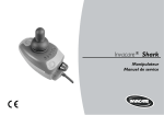
SERVICE MANUAL
®
Invacare Meteor
This manual contains instructions about
troubleshooting and repair
Edition: 02.05.2002
Invacare®Meteor
Service Manual
Contents
Chapter
1
2
3
Page
General information .......................................................................................... 5
1.1
Before you start...................................................................................................................... 5
1.2
Qualifications for service technicians..................................................................................... 5
1.3
Transport back to the manufacturer....................................................................................... 5
1.4
Invacare® service .................................................................................................................. 6
Safety and assembly instructions ................................................................... 8
2.1
Symbols used in these service instructions ........................................................................... 8
2.2
Before any inspection or repair work ..................................................................................... 8
2.3
During dismantling/reassembly.............................................................................................. 9
2.4
Before operation / after completion of service work:............................................................ 10
2.5
Tool list ................................................................................................................................. 10
Overview of the Invacare® Meteor.................................................................. 11
3.1
Scooter layout, components, displays and controls............................................................. 11
3.2
Scooter models, colours and accessories ........................................................................... 11
3.2.1
Scooter models and colours ............................................................................................ 11
3.2.2
Accessories...................................................................................................................... 11
4
Inspection plan ................................................................................................ 12
5
Operational faults............................................................................................ 13
6
7
5.1
General................................................................................................................................. 13
5.2
Fault causes......................................................................................................................... 14
Electronic error codes .................................................................................... 15
6.1
General................................................................................................................................. 15
6.2
Error code description .......................................................................................................... 15
Repair and replacement.................................................................................. 17
7.1
2
Seat unit ............................................................................................................................... 17
7.1.1
General ............................................................................................................................ 17
7.1.2
Armrests........................................................................................................................... 18
7.1.3
Armrest mountings........................................................................................................... 18
7.1.4
Headrest .......................................................................................................................... 18
Service Manual
Invacare® Meteor
7.1.5
Seat belt........................................................................................................................... 19
7.1.6
Seat.................................................................................................................................. 19
7.1.7
Release lever ................................................................................................................... 20
7.1.8
Seat rails .......................................................................................................................... 20
7.1.9
Top seat tube ................................................................................................................... 21
7.1.10
7.2
Seat plate .................................................................................................................... 21
Handlebar, operating console .............................................................................................. 22
7.2.1
General ............................................................................................................................ 22
7.2.2
Operating console and keypad ........................................................................................ 24
7.2.3
Steering column shroud................................................................................................... 25
7.2.4
Steering column adjustment Bowden cable .................................................................... 25
7.2.5
Drive regulator ................................................................................................................. 26
7.2.6
Potentiometer................................................................................................................... 27
7.2.7
Lightbulbs, front ............................................................................................................... 27
7.2.8
Headlights ........................................................................................................................ 28
7.2.9
Handlebar ........................................................................................................................ 28
7.2.10
7.3
Steering column........................................................................................................... 29
Shrouds ................................................................................................................................ 30
7.3.1
Front shroud (three-wheeled version) ............................................................................. 30
7.3.2
Front shroud (four-wheeled version) ............................................................................... 31
7.3.3
Rear shroud (three and four-wheeled version)................................................................ 32
7.3.4
Lightbulbs, rear ................................................................................................................ 32
7.4
Wheels ................................................................................................................................. 33
7.5
Disc brake ............................................................................................................................ 33
7.5.1
Brake Bowden cable........................................................................................................ 33
7.5.2
Brake calliper ................................................................................................................... 34
7.5.3
Brake disc ........................................................................................................................ 34
7.6
Front wheel suspension, three-wheeled version.................................................................. 35
7.6.1
General ............................................................................................................................ 35
7.6.2
Front wheel axle .............................................................................................................. 37
7.6.3
Shock absorber, front ...................................................................................................... 38
7.6.4
Wheel fork........................................................................................................................ 39
7.7
Front wheel suspension, four-wheeled version.................................................................... 40
7.7.1
General ............................................................................................................................ 40
7.7.2
Shock absorber, front ...................................................................................................... 41
3
Invacare®Meteor
7.7.3
Steering linkage ............................................................................................................... 42
7.7.4
Stub axle .......................................................................................................................... 44
7.7.5
Transverse control arm.................................................................................................... 44
7.7.6
Fork steering tube............................................................................................................ 45
7.8
Batteries ............................................................................................................................... 46
7.8.1
Checking the battery (batteries) cable and fuses ............................................................ 46
7.8.2
Removing or refitting battery (batteries) .......................................................................... 46
7.9
Electronic box....................................................................................................................... 47
7.9.1
Removing the electronic box ........................................................................................... 47
7.9.2
Refitting the electronic box .............................................................................................. 47
7.10
4
Service Manual
Drive ..................................................................................................................................... 48
7.10.1
Disassembly ................................................................................................................ 48
7.10.2
Reassembly................................................................................................................. 49
7.10.3
Replacing carbon brushes........................................................................................... 49
Service Manual
1
General information
1.1
Before you start
Invacare® Meteor
This service manual contains information and servicing instructions which are necessary for the
maintenance and overhaul of the Invacare® Meteor.
All maintenance and overhaul work must be carried out in accordance with these repair instructions.
Information contained in the operating manual also applies to general maintenance and care work.
Observe the safety information.
You can find information about ordering spare parts in the spare parts catalogue.
1.2
Qualifications for service technicians
The Meteor may only be maintained and overhauled by qualified personnel. Minimum requirements:
!
Relevant training such as bicycle or orthopaedics mechanic or suitable long-term professional
experience.
!
Safe handling of electrical measurement instruments (multimeter).
1.3
Transport back to the manufacturer
If the Meteor has to be shipped back to the manufacturer for major repairs, you should always use the
original packaging for transport.
You should also include as accurate a fault description as possible.
5
Invacare®Meteor
Service Manual
Invacare® service
1.4
If you have problems or questions please contact Invacare® service:
®
®
Invacare Deutschland GmbH
Invacare A/S
Dehmer Str. 66
D-32549 Bad Oeynhausen
Sdr. Ringvej 39
2605 Brøndby
Deutschland
Danmark
# (Kundendienst):
+49 - (0) 5731 - 754 580
# (Technische Hotline): +49 - (0) 5731 - 754 570
Fax (Kundendienst):
+49 - (0) 5731 - 754 216
Fax (Technische Hotline):+49 - (0) 5731 - 754 208
# (Kundeservice):
Fax (Kundeservice):
®
+45 - (0) 3690 0000
+45 - (0) 3690 0001
®
Invacare , SA
Invacare POIRIER
c/ Areny, s/n
Poligon Industrial de Celrà
17460 Celrà (Girona)
Les Roches
F-37230 Fondettes
France
ESPAÑA
#:
Fax:
+34 - (0) 972 - 49 32 00
+34 - (0) 972 - 49 32 20
®
# (Service Après-Vente):+33 - (0) 2 47 - 62 64 15
Fax (Service Après-Vente):+33 - (0) 2 47 - 62 64 64
Invacare Ltd
Mecc San S.R.L.
South Road
Bridgend Industrial Estate
Bridgend
Mid Glamorgan - CF31-3PY
Via Dei Pini, 35
I - 36016 Thiene (VI)
United Kingdom
#:
Fax:
ITALIA
+39 - (0) 445-380059
+39 - (0) 445-380034
# (Customer Service): +44 - (0) 1656 - 647 372
Fax (Customer Service): +44 - (0) 1656 - 649 016
®
®
Invacare AS
Invacare NEDERLAND
Grensesvingen 9
0603 Oslo
Celsiusstraat 46
NL-6716 BZ Ede
Norge
The Netherlands
# (Kundeservice):
Fax (Kundeservice):
6
+47 - 22 57 95 10
+47 - 22 57 95 01
#:
Fax:
+31 - (0) 318 - 69 57 57
+31 - (0) 318 - 69 57 58
Service Manual
®
Invacare® Meteor
®
Invacare PORTUGAL Lda
Invacare AB
Rua Senhora de Campanhã, 105
4369-001 Porto
Fagerstagatan 9
163 91 Spånga
PORTUGAL
Sverige
#:
Fax:
+352-225105946
+352-225105739
# (Kundtjänst):
Fax (Kundtjänst):
[email protected]
+46 - (0) 8 761 70 90
+46 - (0) 8 761 81 08
Service
®
Invacare JÄRFÄLLA
#:
+46 - (0) 8 – 621 08 44
Fax:
+46 - (0) 8 – 621 08 45
[email protected]
Invacare® S.A. Belgium
MÖLNDAL
Autobaan 14
8210 Loppem (Brugge)
#:
+46 - (0) 31 – 86 36 00
Fax:
+46 - (0) 31 – 86 36 06
[email protected]
BELGIUM
# (Kundeservice):
Fax (Kundeservice):
+32 (50) 831010
+32 (50) 831011
LANDSKRONA
#:
Fax:
[email protected]
+46 - (0) 418 – 285 40
+46 - (0) 418 – 180 89
OSKARSHAMN
#:
+46 - (0) 491 – 101 40
Fax:
+46 - (0) 491 – 101 80
[email protected]
• Alterations to the Meteor which occur as a result of incorrectly or improperly executed maintenance
or overhaul work lead to the exclusion of all liability on the side of Invacare®.
7
Invacare®Meteor
2
Service Manual
Safety and assembly instructions
The safety instructions are intended to prevent accidents at work and it is imperative that they are
observed.
2.1
$
Symbols used in these service instructions
NOTE:
This symbol identifies notes on correct carrying out of service measures, in addition to
specialities and simplifications during disassembly and reassembly.
Caution:
The Caution symbol identifies potential hazards for the service technician or
for the Invacare® Meteor. Always take careful note of any safety instructions
identified through the use of this symbol. Serious injury hazards or danger to
life are additionally identified through the use of the "Hazard!" symbol.
2.2
Before any inspection or repair work
Caution:
HAZARD!
Please note the high weight of some components. This applies especially to
removal of drive units and batteries. Make sure that you are able to remove
and deposit the components safely during the relevant disassembly work.
Caution:
HAZARD!
Danger of injury! Remove any metal watches or rings or metal chains
before carrying out any service work on the batteries. Risk of shortcircuit at batteries or any cables or components directly connected with
the batteries. A short-circuit can lead to serious injuries.
Please read this repair manual and the relevant operating manual carefully before carrying out any
work and observe all information given. Observe the minimum requirements for carrying out the work
(see chapter entitled " General information).
The Invacare® Meteor must be switched off before removal of voltage-carrying components. First
remove the negative and then the positive terminal clamp from the battery, and then remove the
batteries.
8
Service Manual
Invacare® Meteor
Use only undamaged tools in good condition.
When making measurements on voltage-carrying components, avoid short-circuiting the contacts.
2.3
During dismantling/reassembly
Mark all current settings for the wheelchair (seat, armrests, backrest etc.), and the associated cable
connecting plugs, before any removal. This makes reassembly easier. As a basic rule, all work is
described for the process of disassembly. If no other information is given regarding reassembly or
reconstruction, you should assume that reassembly is carried out in reverse order to the stages used
in disassembly. Any discrepancies to the actions used in disassembly, or special information about
reassembly, can always be found at the end of the disassembly description.
Caution:
Prop up the wheelchair with appropriate supports before starting the
disassembly or assembly.
Never use "normal" nuts instead of self-locking nuts.
Always use correctly dimensioned washers or spacers.
$
Note:
Connecting plugs
All plugs are fitted with a mechanical safety device which prevents release of the connecting
plugs during operation. To release the connecting plugs the locking device must be pressed
together in the upper or lower plug area.
When reassembling ensure that the locking device is correctly engaged.
Batteries:
If the Invacare® Meteor needs to be laid on its side for the purpose of carrying out service
work, the batteries must be removed first.
Orientation:
Information about orientation such as "left" or "right" always relates to the view in the
direction of travel, whereby the observer is standing behind the Meteor.
9
Invacare®Meteor
2.4
Service Manual
Before operation / after completion of service work:
Caution:
Check all fixings for tight fit. Check all parts for correct interlocking. Only
operate the wheelchair with correct tyre pressure (2.0 bar).
Always carry out a functional test of any components replaced in addition to a
trial run after completing any service work.
2.5
Tool list
You will need a standard tool set with at least the following:
!
set of open and ring spanners
!
set of Allen keys
!
torque wrench (commercial)
!
socket spanner set
!
set of screwdrivers (flat, Phillips and Torx)
!
oblique pliers
!
flat-nosed pliers
!
circle pliers
!
pointed pliers
!
cable lug pliers
!
wooden or plastic hammer
!
tyre repair kit (commercial)
!
tyre pressure indicator
!
air pump
!
valve removal tool
!
internal remover and insertion or impact tool for ball bearings
!
Multimeter with probes and various cable clips
!
soldering iron 30 W
!
pop riveting tool
10
Service Manual
Invacare® Meteor
3
Overview of the Invacare® Meteor
3.1
Scooter layout, components, displays and controls
The following picture shows the layout of a Meteor. Removal and reassembly of spare parts is
described in Chapter .7
$
NOTE:
The display arrangement and controls for the three or four-wheel Meteor is the same. The
three-wheel Meteor is used as an example in the following picture.
1.
Throttle lever
2.
Tiller adjustment lever
3.
Operating console
4.
Brake lever
5.
Keyswitch (ON/OFF)
6.
Sliding seat lever (front right below seat)
7.
Release lever for rotating and removing seat (right
below seat)
8.
Disengaging lever.
3.2
Scooter models, colours and accessories
3.2.1
Scooter models and colours
The Invacare® Meteor is available as a three- or four-wheel version with the following options:
•
Colour
%
Ruby red
%
Sapphire blue
3.2.2
Accessories
The following accessories are available for the Invacare® Meteor
•
Basket assy. (rear)
•
Cane holder assy.
•
External mirror (right and / or left)
11
Invacare®Meteor
4
Service Manual
Inspection plan
Component
Wheels and
suspension
units
Check
Remedy
Chapter:
•
Check drive wheels for
tight fit and side play
⇒ Adjust, replace
see
operating
manual
•
Check front wheels for
tight fit, float and side
play
⇒ Adjust, replace wheel, axle, see
operating
wheel bearing or fork
manual
7.6, 7.7
•
Check front wheel forks
⇒ Replace bearing
7.6, 7.7
•
Check tyres
⇒ Fit new
see
operating
manual
•
Check cabling
⇒ Replace cable if necessary
•
Check function
⇒ Replace bulbs or cables if
necessary
Drive
•
Check functions in drive
and push modes
⇒ Replace drive units, carbon 7.10
brushes if necessary
Chassis
•
Check screw connections ⇒ Tighten screws / nuts,
and battery straps.
adjust or replace if
necessary
Batteries
•
Damage to batteries,
corrosion on contacts
⇒ Clean contacts, replace
batteries
•
Check contacts, terminal
clamps, cables and strip
fuses
⇒ Tighten, clean, replace if
necessary
•
Check battery voltage
⇒ Charge batteries / replace
•
Operating console, status ⇒ Check cables, plugs and
display flashing
sensors
•
Cable, connecting plug
Lighting
Operating
console
12
⇒ Tighten, replace
7.2.7,
7.3.4
7.8.1
$
Service Manual
5
Operational faults
5.1
General
Invacare® Meteor
The electronic system offers diagnostic information to support the technician during the recognition
and rectification of faults within the system. If a fault is present, the status display (the outside left LED
of the battery charger display) will blink in groups with small pauses. The type of error is displayed by
the number of blinks in each group, which are also known as the "error code" or "error code".
The electronic system reacts differently depending on the seriousness of the fault and its effect on
user safety. It can, for example:
!
simply show the error code as a warning and allow both driving and operation to continue
!
display the error code, stop the Meteor and hold it at a standstill until the electronic system has
been switched off and switched on again
!
display the error code, stop the Meteor and not permit further driving until the fault has been
rectified.
If faults occur in drive mode or power supply proceed as follows:
!
First assess the fault causes described in Section 5.2.
!
Check the status display at the operating console and evaluate the error codes in accordance with
Section 6.2.
!
Carry out the necessary testing / repairs. While doing this please note the references to the
appropriate chapter in the manual or to the appropriate documentation.
13
Invacare®Meteor
5.2
Service Manual
Fault causes
Fault description
Fault cause
Fault remedy
Wheelchair will not start
disengaging lever set to "Rear",
motor disengaged
push disengaging lever forwards
operating unit status display has
gone out
• batteries defective
replace batteries
• completely discharge battery pre-charge batteries
• power supply interrupted
• check battery fuse.
• check voltage at operating
console
• check voltage at batteries
Drive motor judders in drive
mode
Cannot charge batteries
status display blinking on
wheelchair
assess error code
drive unit defective
replace drive unit
carbon brushes defective
replace carbon brushes.
batteries defective
replace battery
charging device defective
replace charging device
Warning horn defective
check warning horn / replace if
necessary
Lighting defective
• check lighting (bulbs) /
replace if necessary
• check cabling / replace if
necessary
14
Invacare® Meteor
Service Manual
6
Electronic error codes
6.1
General
Before assessing error codes, carry out the following test:
!
Turn the operating console on and off several times.
The test checks whether the error can be automatically rectified by the electronics, and if necessary
deactivates the blinking status display at the operating console. If this is not the case, you can locate
the fault using the error codes as follows:
!
Turn the operating console on and off.
!
Check which error code is showing by counting.
!
Wait for the error code pause (approx. 2-3 seconds).
!
Recount the error code just to make sure.
6.2
Error code description
Check the display, the LED on the outside left of the battery charge display, and the electronics
(operating console).The following list is based on the error code:.
Error code
Fault
Consequence for
the Meteor
Comments
1x
Battery voltage too
low
Continues to drive
Battery voltage has dropped below 23.3
V. Charge battery as soon as possible
2x
Battery voltage too
low
Stops driving
Battery voltage has dropped below 16.5
V. Recharge battery
If you switch the Meteor off for a few
minutes, the battery can often recharge
itself to such a level that a short run is
still possible.
Lifter is raised
Reduced driving
speed
Completely lower lifter.
15
Invacare®Meteor
Service Manual
Error code
Fault
Consequence for
the Meteor
Comments
3x
Battery voltage too
high
Stops driving
The battery voltage has risen to over 32
V (due to running downhill too fast or
defective battery charger).
If the battery charger is connected,
disconnect it from the Meteor.
The electronic system charges the
batteries when running downhill and
when braking. This fault is caused when
the battery voltage becomes too high
during this process. Switch the Meteor off
and on again
4x
Current delay
exceeded
Stops driving
The maximum current has been
exceeded for too long a period, the motor
is probably overloaded or has been
running against an immovable obstacle
for too long. Switch the Meteor off, wait a
few minutes and then switch it on again.
The electronic system has determined a
motor short-circuit. Check the wiring
harness for short-circuit and check the
motor.
5x
Brake failure
Stops driving
Brake circuit
interruption
6x
Ensure that the disengaging lever is
pressed in.
There is a defect in the braking coil or in
the cabling. Check magnetic brake and
cabling for open or short-circuit.
Meteor not in neutral Stops driving
when switched on
Drive lever is not in neutral when the
keyswitch is turned. Set the drive lever in
neutral, turn off and then turn on again.
It may be necessary to recalibrate the
drive lever.
7x
Fault in speed
potentiometer
Stops driving
The drive lever electronics could be faulty
or incorrectly connected.
8x
Motor fault
Stops driving
The motor or its cabling is defective
9x
Internal faults
Stops driving
Check electronic box
16
Service Manual
7
Repair and replacement
7.1
Seat unit
Invacare® Meteor
Caution:
Seat adjustments such as seat depth, seat height, backrest angle and
distance between armrests or the steering column should be
individually adjusted to suit the user. The settings should be called up
once again when service work is completed
7.1.1
General
The seat unit individual parts are shown in the following drawing:
17
Invacare®Meteor
7.1.2
Armrests
Disassembly
1.
Loosen the handwheel under the armrest.
2.
Pull the armrest out upwards.
Reassembly
1.
Reassembly takes place in reverse order to disassembly.
7.1.3
Armrest mountings
Disassembly
1.
Loosen handwheel beneath seat.
2.
Withdraw armrest mounting to the side.
Reassembly
1.
Reassembly takes place in reverse order to disassembly.
7.1.4
Headrest
1.
Pull out the headrest while keeping the release
button below the headrest pressed down.
2.
Reassembly takes place in reverse order to
disassembly.
18
Service Manual
Service Manual
7.1.5
Invacare® Meteor
Seat belt
Caution:
Only replace the complete seat belt, in other words both the left-hand
and right-hand part together.
Disassembly
1.
Loosen the Allen screw each side for the left-hand
and right-hand seatbelt, and remove together with
the seatbelt and one washer each.
Reassembly
1.
Reassembly takes place in reverse order to disassembly.
7.1.6
Seat
Caution:
Fold the backrest completely forwards onto the seat area to avoid
danger of tipping once the screws have been removed.
Disassembly
1.
Pull the release lever upwards, turn the seat a
quarter turn to the left or right and raise the seat
from the seat support.
2.
Place the seat on a stable support.
Reassembly
1.
Place the seat on the seat support and lift the
release lever upwards.
2.
Allow the seat to slide within the seat support and
19
Invacare®Meteor
Service Manual
engage by turning slightly.
3.
Let release lever go.
7.1.7
Release lever
Caution:
Risk of crushing when working on slide rails, adjustment levers and
springs!
Disassembly
1.
Dismantle seat (see section 7.1.2).
2.
Turn the seat round with the backrest folded down.
3.
Loosen the release lever hex nut located under the
seat support.
4.
Disengage the torsion springs and replace release
lever.
Reassembly
1.
Reassembly takes place in reverse order to disassembly.
7.1.8
Seat rails
Disassembly
Caution:
Risk of crushing when working on slide rails, adjustment levers and
springs!
1.
Dismantle seat (see section 7.1.2).
2.
Turn the seat round with the backrest folded down.
3.
Loosen the handwheel beneath the seat, pull the
armrest supports with the armrests out to the side.
4.
Unscrew all four hex nuts from the seat support and
remove the seat support.
5.
Unscrew the Allen screws on the seat edge rails
and replace the seat rails.
20
Service Manual
Invacare® Meteor
Reassembly
1.
Reassembly takes place in reverse order to disassembly.
7.1.9
Top seat tube
Disassembly
1.
Dismantle seat (see section 7.1.2).
2.
Unscrew the hex bolts and nuts from the seat
attachment and remove together with washers.
3.
Pull the seat tube out and replace.
Reassembly
1.
Reassembly takes place in reverse order to disassembly.
7.1.10
Seat plate
Disassembly
1.
Dismantle seat (see section 7.1.2).
2.
Dismantle the top seat tube (see section 7.1.9).
3.
Remove the Allen screw together with washers and
nuts.
4.
Remove the seat plate.
Reassembly
1.
Reassembly takes place in reverse order to disassembly.
21
Invacare®Meteor
7.2
Service Manual
Handlebar, operating console
Caution:
Make sure you put the vehicle on blocks before working
Caution:
Risk of accidents!
Always carry out a functional test and a trial run after service work on
the drive lever or electronics!
7.2.1
General
The handlebar and steering column individual parts are shown in the following drawings.
22
Service Manual
Invacare® Meteor
23
Invacare®Meteor
7.2.2
Operating console and keypad
Disassembly
1.
Remove plastic caps.
2.
Loosen Allen screws and washers and remove.
3.
Carefully lift up operating console.
4.
Remove the caps from the turret, and dismantle the
turret.
5.
Unscrew the operating circuit board.
6.
Withdraw the conductor foil with plug.
7.
Raise the double-layer keypad with a flat tool at any
one location, and pull off.
8.
Remove any adhesive remains from the selfadhesive foil.
Reassembly
1.
24
Reassembly takes place in reverse order to disassembly.
Service Manual
Service Manual
7.2.3
Invacare® Meteor
Steering column shroud
Disassembly
1.
Loosen the screw connections between front and
rear steering column shroud.
2.
Remove the Phillips screws.
3.
Dismantle the rear steering column shroud.
4.
Loosen the screw connections between front
steering column shroud and the basket holder.
5.
Remove the Allen screws and the basket holder.
6.
Carefully remove the front steering column shroud.
7.
Pull out the keyswitch complete with wiring harness
from the control panel and remove front shroud.
Reassembly
1.
Reassembly takes place in reverse order to disassembly.
7.2.4
Steering column adjustment Bowden cable
Disassembly
1.
Dismantle the operating console (see section 7.2.2).
2.
Dismantle the rear steering column shroud (see
section 7.2.3).
3.
Note down the Bowden cable route (sketch).
4.
Loosen the union nut on the Bowden cable at the
handle.
5.
Twist the Bowden cable nut out of the handle.
25
Invacare®Meteor
6.
Loosen the Phillips screw at the end of the Bowden
cable out of the clamping sleeve and pull the
Bowden cable out of the attachment.
7.
Draw the clamping sleeve off the Bowden cable.
8.
Remove the Bowden cable
Reassembly
1.
Reassembly takes place in reverse order to disassembly.
7.2.5
Drive regulator
Disassembly
1.
Dismantle the operating console (see section 7.2.1).
2.
Loosen the potentiometer fixing.
3.
Remove the Phillips screws.
4.
Loosen the Allen screws located on the side of the
potentiometer.
5.
Pull the drive regulator out downwards.
Reassembly
1.
26
Reassembly takes place in reverse order to disassembly.
Service Manual
Service Manual
7.2.6
Invacare® Meteor
Potentiometer
Disassembly
1.
Dismantle the operating console (see section 7.2.1).
2.
Loosen the potentiometer fixing.
3.
Remove the Phillips screws.
4.
Loosen the Allen screws located on the side of the
potentiometer.
5.
Pull the potentiometer out downwards.
6.
Strip the potentiometer cable of its insulation and
de-solder.
7.
Dismantle the spring, hex nut and U rail.
Reassembly
Caution:
When reassembling, ensure that the potentiometer or drive regulator is
set to middle setting. Risk of accidents! The potentiometer has a
standard value of around 5 kOhm. You must ensure that the
potentiometer for the right-hand or left-hand connection to middle
setting has exactly the same value using a digital multimeter.
1.
Reassembly takes place in reverse order, and make sure you set the potentiometer to
middle setting.
7.2.7
Lightbulbs, front
Disassembly
1.
Dismantle the control elements (see section 7.2.1).
2.
Loosen the Phillips screw.
27
Invacare®Meteor
3.
Remove the headlight when it has been angled from
bottom to top.
4.
Turn bulb holder out together with bulb.
5.
Replace bulb.
Reassembly
1.
Reassembly takes place in reverse order to disassembly.
7.2.8
Headlights
Disassembly
1.
Remove the bulbs (see section 7.2.7).
2.
Remove headlights.
Reassembly
1.
Reassembly takes place in reverse order to disassembly.
7.2.9
Handlebar
Disassembly
1.
28
Disassembly of the handlebar is shown in the
adjacent exploded drawing.
Service Manual
Service Manual
Invacare® Meteor
Reassembly
1.
Reassembly takes place in the reverse order.
7.2.10
Steering column
Disassembly
1.
Disassembly of the steering column takes place as
shown in the adjacent exploded drawing.
Reassembly
1.
Reassembly takes place in the reverse order.
29
Invacare®Meteor
7.3
Shrouds
7.3.1
Front shroud (three-wheeled version)
Service Manual
General
The individual parts of the front panel shroud (3-wheeled version) are shown in the following drawing.
Disassembly
1.
Dismantle the steering column (see section 7.2.10.
2.
Dismantle the rear shroud (see section 7.3.3).
3.
Remove foot mat.
4.
Loosen four Phillips screws.
5.
Remove front shroud.
Reassembly
1.
30
Reassembly takes place in reverse order to
disassembly.
Service Manual
7.3.2
Invacare® Meteor
Front shroud (four-wheeled version)
General
The individual parts of the front panel shroud (4-wheeled version) are shown in the following drawing.
Disassembly
1.
Dismantle the steering column (see section 7.2.10.
2.
Dismantle the rear shroud (see section 7.3.3).
3.
Remove foot mat.
4.
Loosen four Phillips screws.
5.
Remove front shroud.
Reassembly
1.
Reassembly takes place in reverse order to
disassembly.
31
Invacare®Meteor
7.3.3
Service Manual
Rear shroud (three and four-wheeled version)
The individual parts of the rear panel shroud are shown in the following drawing.
Disassembly
1.
Dismantle seat (see section 7.1.2).
2.
Loosen side Velcro fastenings.
3.
Loosen cable connections.
4.
Remove rear shroud.
Reassembly
1.
Reassembly (3 and 4-wheeled versions) takes place
in reverse order to disassembly.
7.3.4
Lightbulbs, rear
Disassembly
1.
Remove rear shroud (see section 7.3.3).
2.
Unscrew the bulb together with bulb holder out of
the rear shroud.
3.
Replace the bulb.
Reassembly
1.
32
Reassembly takes place in reverse order to disassembly.
Service Manual
7.4
$
Invacare® Meteor
Wheels
NOTE:
Disassembly of wheels and repair of tyres is described in the operating manual.
7.5
Disc brake
7.5.1
Brake Bowden cable
Disassembly
1.
Dismantle the operating console (see section 7.2.2).
2.
Dismantle the rear steering column shroud (see
section 7.2.3).
3.
Dismantle the rear shroud (see section 7.3.3).
4.
Note down the Bowden cable route (sketch).
5.
Loosen the Bowden cable clamp Allen screw at the
brake saddle.
6.
Loosen the brake Bowden cable union nut.
7.
Twist the Bowden cable nut out of the brake saddle.
8.
Loosen the union nut on the Bowden cable at the
handle.
9.
Twist the Bowden cable nut out of the handle.
10.
Mark the cable binder positions along the brake
Bowden cable route and release them.
11.
Remove brake Bowden cable.
Reassembly
1.
Reassembly takes place in reverse order to
disassembly.
2.
Adjust brake Bowden cable.
33
Invacare®Meteor
7.5.2
Service Manual
Brake calliper
Caution:
Before starting work, lay the vehicle down on its side on a relatively
firm underlay, or put the vehicle on blocks.
Disassembly
1.
Dismantle the brake Bowden cable (see section
7.5.1).
2.
Loosen the Allen screws at the brake calliper and
remove them together with washers.
3.
Pull the brake calliper off the brake disc.
Reassembly
1.
Push the brake calliper back over the brake disc.
2.
Bolt to the brake calliper to the chassis with Allen
keys and washers.
3.
Fit the brake cable and adjust.
7.5.3
Brake disc
Caution:
Before starting work, lay the vehicle down on its side on a relatively
firm underlay, or put the vehicle on blocks.
Disassembly
1.
Dismantle drive wheel (see section 7.4).
2.
Dismantle brake calliper (see section 7.5.1).
3.
Remove distance ring and brake disc from the axle.
Reassembly
1.
Fit the brake disc to the drive wheel on the right.
2.
Fit the drive wheel (see section 7.4).
3.
Fit the brake calliper (see section 7.5.1).
34
Service Manual
7.6
Invacare® Meteor
Front wheel suspension, three-wheeled version
Caution:
Before starting work, lay the vehicle down on its side on a relatively
firm underlay so that the front wheel is not loaded and is easily
accessible from both sides, or put the vehicle on blocks.
7.6.1
General
The individual parts front for the wheel suspension, 4-wheeled version, are shown in the following
drawing.
35
Invacare®Meteor
36
Service Manual
Service Manual
7.6.2
Invacare® Meteor
Front wheel axle
Disassembly
1.
Dismantle the front wheel (see section 7.4).
2.
Remove the sleeve and collar from the left-hand
side of the wheel, then the sleeve and collar from
the right.
3.
Pull the axle out of the wheel.
Reassembly
$
NOTE:
The left-hand side of the wheel is labelled with the word Invacare® on the top wheel flange.
1.
Push the axle through the wheel.
2.
Fit the washer and sleeve over the axle (right-hand
wheel side).
3.
Fit the collar and sleeve over the axle (left-hand
wheel side).
37
Invacare®Meteor
7.6.3
Shock absorber, front
Disassembly
1.
Dismantle the front shroud (see section 7.3.1).
2.
Loosen the spring holder (turn collar) and slacken
coil spring.
3.
Loosen nuts from top and bottom suspension.
4.
Pull the shock absorbers (with coil springs) and
washers from top and bottom suspension.
Reassembly
1.
Fit the shock absorbers (with coil springs) and
washers onto the top and bottom suspension.
2.
Place the nuts on the top and bottom suspension
and screw tight.
3.
Tighten the spring holders and tension the coil
spring.
38
Service Manual
Service Manual
7.6.4
Invacare® Meteor
Wheel fork
Disassembly
1.
Dismantle the steering column (see section 7.2.10.
2.
Dismantle the front shroud (see section 7.3.1).
3.
Dismantle the front wheel (see section 7.4).
4.
Dismantle the shock absorber (see section 7.6.3).
5.
Unscrew the top union nut.
6.
Remove the angled panel.
7.
Unscrew the bottom union nut.
8.
Pull the wheel fork out downwards.
9.
Pull the bearing set out of the chassis bearing
sleeve and then remove the wheel fork.
Reassembly
1.
$
Reassembly takes place in reverse order to
disassembly.
NOTE:
The bearing must be adjusted using the bottom
union nut. The bearing must not be allowed to have
any play, and the wheel fork must turn easily.
39
Invacare®Meteor
7.7
Service Manual
Front wheel suspension, four-wheeled version
Caution:
Before starting work, lay the vehicle down on its side on a relatively
firm underlay so that the front wheel is not loaded and is easily
accessible from both sides, or put the vehicle on blocks.
7.7.1
General
The individual parts for the front wheel suspension, 4-wheeled version, are shown in the following
drawing.
40
Service Manual
7.7.2
Invacare® Meteor
Shock absorber, front
Disassembly
1.
Dismantle the front shroud (see section 7.3.2).
2.
Loosen the spring holder (turn collar) and slacken
coil spring.
3.
Remove the bottom Allen screw, the Allen screw
with internal threads, two collars and the sleeve.
4.
Remove the top nut, two washers and the collar.
5.
Pull the shock absorber (with coil spring) and collar
off the top suspension.
Reassembly
1.
Place the collar on the top suspension.
2.
Locate the shock absorber (with coil spring), collar
and two washers.
3.
Tighten the nut.
4.
Insert the sleeve centrally in the bottom shock
absorber spring holder.
5.
Put one collar on each side of the sleeve.
6.
Fit the shock absorber with the Allen screw with
internal thread, and the Allen screw, and screw up
tight.
7.
Tighten the spring holders and tension the coil
spring.
41
Invacare®Meteor
7.7.3
Steering linkage
Disassembly of the steering linkage
1.
Dismantle the front shroud (see section 7.3.2).
2.
Remove the nut, washer and the stop.
3.
Remove the Allen screw.
4.
Remove the TO linkage (to fork steering tube),
washer and FROM linkage (to right-hand wheel).
5.
Push the TO linkage upwards.
6.
Hold the ball pin axle up with flat-nosed players
between the FROM linkage and the stub axle.
7.
Loosen the nut, and remove together with FROM
linkage.
8.
Push the FROM linkage upwards.
9.
Hold the ball pin axle up with flat-nosed players
between the TO linkage and the fork steering tube.
10.
Loosen the nut, and remove together with TO
linkage.
42
Service Manual
Service Manual
Invacare® Meteor
Reassembly of steering linkage
$
NOTE:
When reassembling the steering linkage, you must adjust it so that the steering is located
centrally and the tracking is parallel.
The stop must be adjusted when reassembling.
1.
Fit the FROM linkage (to fork steering tube), washer
and TO linkage (to right-hand wheel) with the Allen
screw in the left-hand stub axle.
2.
Screw the stop, washer and nut to the Allen screw
below the stub axle.
3.
Fit the FROM linkage ball pin into the right-hand
stub axle, and fit the washer and nut.
4.
Raise the FROM linkage.
5.
Hold the ball pin on the FROM linkage up with flatnosed pliers and tighten the nut.
6.
Fit the TO linkage ball pin into the fork steering tube,
and fit the washer and nut.
7.
Raise the TO linkage..
8.
Hold the ball pin on the TO linkage up with flatnosed pliers and tighten the nut.
43
Invacare®Meteor
7.7.4
Service Manual
Stub axle
Disassembly
1.
Dismantle the front shroud (see section 7.3.2).
2.
Remove the front wheel (see section 7.4).
3.
Dismantle the steering linkage (see section 7.7.3.
4.
Remove the nut from the bolted connection.
5.
Remove the nut, collar and the hex bolt.
6.
Remove the stub axle.
Reassembly
1.
Reassembly takes place in reverse order to
disassembly.
7.7.5
Transverse control arm
$
NOTE:
When disassembling or reassembling a transverse control arm, both control arms are
affected when loosening or tightening the internal bolted connection!
Disassembly of the transverse control arm
1.
Dismantle the shock absorber (see section 7.7.1).
2.
Dismantle the steering linkage (see section 7.7.3).
3.
Dismantle the stub axle (see section 7.7.4).
4.
Loosen the nut on the outside assembly eye.
5.
Remove the nut and the Allen screw.
6.
Loosen the nut on the inside assembly eye.
7.
Remove the nut and the Allen screw.
8.
Remove the transverse control arm.
44
Service Manual
Invacare® Meteor
Reassembly of the transverse control arm
1.
Reassembly takes place in reverse order to
disassembly.
7.7.6
Fork steering tube
Disassembly of the transverse control arm
1.
Dismantle the steering column (see section 7.2.10.
2.
Dismantle the steering linkage (see section 7.7.3).
3.
Unscrew the top union nut.
4.
Remove the angled panel.
5.
Unscrew the bottom union nut.
6.
Pull the wheel fork out downwards.
7.
Pull the bearing set out of the chassis bearing
sleeve and then remove the wheel fork.
Reassembly
1.
$
Reassembly takes place in reverse order to
disassembly.
NOTE:
The bearing must be adjusted using the bottom
union nut. The bearing must not be allowed to have
any play, and the wheel fork must turn easily.
45
Invacare®Meteor
7.8
Service Manual
Batteries
Caution:
Observe the safety information (see chapt. 2)! Do not bridge battery
terminals, risk of short circuit! Take care when removing batteries, risk
of crushing! Take off all rings or metal jewellery worn on hands and
wrists.
Always remove the negative battery terminal first and then the positive
battery terminal.
Charging the batteries: see also operating manual.
7.8.1
Checking the battery (batteries) cable and fuses
1.
Check the total voltage at the operating console
charging socket using a multimeter.
Voltage below 24V: charge batteries.
2.
Voltage below 18V: Check individual battery
voltages.
3.
Unclamp battery terminal.
4.
Check voltage across battery terminals.
5.
Voltage under 9V: Charge batteries. If the
undervoltage cannot be rectified by charging,
replace affected battery.
$
Note:
If the individual voltages measured across the
battery terminals are correct, but the total voltage at
the charging socket is not correct, check the cable
and strip fuse blocks.
6.
Carefully unscrew the fuse holder.
7.
Remove the 5AG80 A fuse.
8.
Replace the damaged fuse.
7.8.2
Removing or refitting battery (batteries)
$
46
Note:
Removal and refitting of the batteries is described in the operating manual.
Service Manual
7.9
Invacare® Meteor
Electronic box
Caution:
Remove battery fuses.
Caution:
Before starting work, lay the vehicle down on its side on a relatively
firm underlay so that the chassis floor beneath the electronic box is
easily accessible, or put the vehicle on blocks.
7.9.1
Removing the electronic box
1.
Dismantle the rear shroud (see section 7.3.3).
$
Note:
Note down the position of the cable plugs on the
electronic box.
2.
Remove all cable plugs from the electronic box.
3.
Loosen the electronic box bolted connection on the
chassis floor (four Phillips screws with locknuts).
7.9.2
Refitting the electronic box
1.
Screw the electronic box to the chassis floor using
four Phillips screws and locknuts.
2.
Plug all the cable plugs into the electronic box again
in the positions you noted earlier.
47
Invacare®Meteor
7.10
Service Manual
Drive
Caution:
Make sure you put the vehicle up on blocks before working. The ground
clearance must be at least 150 mm in order to be able to remove the
drive. Please note the high drive unit weight, risk of crushing! Always
carry out a functional test and trial run after service work on the drive.
Risk of accidents!
Caution:
Remove the battery fuses in accordance with the operating manual.
7.10.1
$
Disassembly
NOTE:
Note down the position of the cable plugs on the
electronic box.
1.
Dismantle the rear shroud (see section 7.3.3).
2.
Remove the drive cable plugs.
3.
Dismantle the drive wheels (see section 7.4).
4.
Loosen the axle fixing and bearing bolted
connections.
5.
Remove the Allen screws, washers and nuts.
6.
Remove the axle mounting bracket.
7.
Remove the drive unit.
48
Service Manual
7.10.2
Reassembly
1.
Place the drive unit on the chassis.
2.
Place the axle mounting bracket on the drive unit.
3.
Screw the axle mounting bracket to the chassis
using the Allen screws, washers and nuts.
4.
Plug the drive cable plugs back in in the positions
you noted previously.
7.10.3
Replacing carbon brushes
1.
Dismantle the rear shroud (see section 7.3.3).
2.
Unscrew the four plastic slotted screws out of the
drive unit.
3.
Replace the carbon brushes located behind the
plastic slotted screws.
4.
Reassembly takes place in reverse order to
disassembly.
Invacare® Meteor
49