1
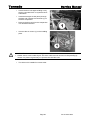
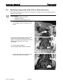
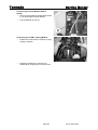
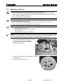
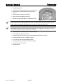
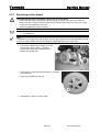
Invacare® Tornado SERVICE MANUAL These instructions contain information about: Troubleshooting Repair Edition: 03.2004 Tornado Service Manual General information These repair instructions contain all the information necessary for maintenance and overhaul of the wheelchair. • All maintenance and overhaul work must be carried out in accordance with these repair instructions. • Please observe all safety instructions. • Information about operation or about general maintenance and care work should be taken from the wheelchair Operating Manual. • You can find information about ordering spare parts in the spare parts catalogue. • Use only genuine Invacare® spare parts. Using parts from any other source will void the warranty! • We reserve the right to make any alterations on the grounds of technical improvements. • The wheelchair may only be maintained and overhauled by qualified personnel. • The minimum requirement for service technicians is relevant training, such as in the cycle or orthopaedic mechanics fields, or suitably long-term job experience. - Experience and knowledge of electrical measuring devices (Multimeter) is also a requirement. - Special Invacare training sessions are recommended. • Alterations to the wheelchair which occur as a result of incorrectly or improperly executed maintenance or overhaul work lead to the exclusion of all liability on the part of INVACARE. • If you have any problems or questions please contact INVACARE SERVICE: Invacare® Deutschland GmbH Invacare® A/S Kleiststraße 49 Sdr. Ringvej 39 32457 Porta Westfalica 2605 Brøndby Deutschland Danmark (Technische Hotline): 01 80 - 5 26 22 64 (Kundeservice): +45 - (0) 3690 0000 Fax (Technische Hotline): 01 80 - 5 26 22 75 Fax (Kundeservice): +45 - (0) 3690 0001 Invacare® POIRIER Les Roches F-37230 Fondettes Invacare®, SA c/ Areny, s/n Poligon Industrial de Celrà 17460 Celrà (Girona) (Service Après-Vente):+33 - (0) 2 47 - 62 64 66 ESPAÑA Fax (Service Après-Vente):+33 - (0) 2 47 - 42 12 24 : +34 - (0) 972 - 49 32 00 Fax: +34 - (0) 972 - 49 32 20 As at: 19.03.2004 France Page 1 Tornado Service Manual Invacare® Ltd Invacare Mecc San s.r.l. South Road Via Dei Pini, 62 Bridgend I - 36016 Thiene (VI) Mid Glamorgan - CF31-3PY ITALIA United Kingdom : +39 - (0) 445-380059 Fax: +39 - (0) 445-380034 (Customer Service): +44 - (0) 1656 - 647 327 Fax (Customer Service): +44 - (0) 1656 - 649 016 Invacare® AS Invacare® B.V. Grensesvingen 9 Celsiusstraat 46 0603 Oslo NL-6716 BZ Ede Norge The Netherlands (Kundeservice): +47 - 22 57 95 10 : +31 - (0) 318 - 69 57 57 Fax (Kundeservice): +47 - 22 57 95 01 Fax: +31 - (0) 318 - 69 57 58 Invacare® PORTUGAL Lda Invacare® AB Rua Senhora de Campanhã, 105 Fagerstagatan 9 4369-001 Porto 163 91 Spånga PORTUGAL Sverige : +351-225105946 (Kundtjänst): +46 - (0) 8 761 70 90 Fax: +351-225105739 Fax (Kundtjänst): +46 - (0) 8 761 81 08 [email protected] Service Invacare JÄRFÄLLA : +46 - (0) 8 – 621 08 44 Fax: +46 - (0) 8 – 621 08 45 [email protected] MÖLNDAL Invacare® n.v. : +46 - (0) 31 – 86 36 00 Autobaan 14 Fax: +46 - (0) 31 – 86 36 06 8210 Loppem (Brugge) [email protected] BELGIUM : +32 (50) 831010 Fax: +32 (50) 831011 LANDSKRONA : +46 - (0) 418 – 285 40 Fax: +46 - (0) 418 – 180 89 [email protected] OSKARSHAMN : +46 - (0) 491 – 101 40 Fax: +46 - (0) 491 – 101 80 [email protected] Page 2 As at:19.03.2004 Tornado Service Manual Notes on transport • If the wheelchair has to be shipped back to the manufacturer for major repairs, you should always use the original packaging for transport. • You should also include as accurate a fault description as possible. The following symbols are used in these repair instructions: 9 Note: This symbol identifies general information which indicate special points or simplifications in dismantling / reassembly. CAUTION: it is imperative that you observe any >safety instructions< identified with this symbol. This symbol identifies service work. Page 4 As at:19.03.2004 Tornado Service Manual Contents 1 SAFETY AND ASSEMBLY INSTRUCTIONS 7 1.1 Before any inspection or repair work 7 1.2 During dismantling/reassembly 7 1.3 After completion of work / before operating the wheelchair: 8 2 TOOL LIST 9 2.1 Tightening torques and Loctite 10 3 LAYOUT OF COMPONENTS AND MODULES 11 4 SERVICE PLAN (1X ANNUALLY) 13 5 TROUBLESHOOTING THE TORNADO 15 5.1 Troubleshooting the Tornado with ACS 5.1.1 Diagnosing driving faults 5.1.2 Diagnosing problems with electric actuators 5.1.3 REM24 Error Codes and Diagnostic Codes 15 15 17 18 5.2 Troubleshooting the Invacare® Tornado with Shark Remote 5.2.1 Diagnosing driving faults 5.2.2 Shark Error Codes and Diagnostic Codes 20 20 22 6 REPAIR WORK 24 6.1 Replacing the drive motors 24 6.2 Replacing components of the ACS or Shark electronics 27 6.3 Replacing batteries 29 6.4 Replacing the main fuse 34 6.5 Checking the cables 36 6.6 Replacing the remote 38 6.7 Testing an actuator motor 39 6.8 Adjusting and replacing the speed reduction switch 40 6.9 Replacing the steering head bearings on the front or rear castor wheels 6.9.1 Front Castor Wheels 6.9.2 Rear Castor Wheels As at: 19.03.2004 Page 5 41 41 43 Tornado Service Manual 6.10 Replacing the Anti-Dive Spring and/or its plastic guides 45 6.11 Repairing a flat tyre 48 6.12 Replacing a drive wheel 50 Page 6 As at:19.03.2004 Tornado Service Manual 1 Safety and assembly instructions These safety instructions are intended to prevent accidents during work and it is imperative that they are observed. 1.1 Before any inspection or repair work • Read and observe this repair manual and the associated operating manual. • Observe the minimum requirements for carrying out the work (see chapter entitled "General information”). Caution: • Please note the heavy weight of some components. This applies especially to removal of drive units and batteries. • The wheelchair must be switched off before removal of voltage-carrying components. To do this, disconnect the batteries or remove them. • When making measurements on voltage-carrying components, avoid short-circuiting the contacts. Danger of fire and combustion ! • Use only undamaged tools in good condition. 1.2 During dismantling/reassembly • Mark all current settings for the wheelchair (seat, armrests, backrest etc.), and the cable connecting plugs associated, before any removals. This makes reassembly easier. Caution: • Prop up the lifted wheelchair with appropriate supports before starting the disassembly or assembly. • Never use standard nuts instead of self-locking nuts. • Always use correctly dimensioned washers or spacers. 9 Note: • All plugs are fitted with mechanical safety devices which prevent release of the connecting plugs during operation. • To release the connecting plugs the safety devices must be pressed in. • When reassembling ensure that these safety devices are correctly engaged. • Cable binders which have been cut off during disassembly should be replaced by new ones during reassembly. As at: 19.03.2004 Page 7 Tornado 1.3 Service Manual After completion of work / before operating the wheelchair: Caution: • Check all fixings for tight fit. • Check all parts for correct interlocking. • Only operate wheelchair with correct tyre pressure (2.5 bar). • Check electrical components for correct functioning, incorrect polarity of cables can result in damage to the electronics. As a last check, always carry out a test-drive. Page 8 As at:19.03.2004 Tornado Service Manual 2 Tool list You will need a standard tool set with at least the following: • set of open and ring spanners (6 – 24 mm) • set of Allen keys (1.5 - 10 mm) • torque wrench (commercial) • socket spanner set • set of screwdrivers (0.5 - 1.6 mm) • oblique pliers • flat-nosed pliers • circlip pliers • pointed pliers • cable lug pliers • wooden or plastic hammer • tyre repair kit (commercial) • tyre pressure indicator • valve removal tool • wheel bearing puller • multimeter with probes and various cable clips • soldering iron 30 W • front wheel hub puller (available from INVACARE Service) • circlip pliers for star lock caps (commercially available, make Tigtemeyer) • pop riveting tool • stepped mandrel As at: 19.03.2004 Page 9 Tornado 2.1 Service Manual Tightening torques and Loctite The tightening torques stated in the following table are dependent on the thread diameters for the nuts and bolts for which no special values are determined. All values apply to dry and grease-free threads. Thread diameter Unit M5 M6 M8 M10 M12 M16 Nm 3.4-4.9 5.9-7.8 14-19 25-34 44-61 115-155 mkp 0.35-0.80 0.60-0.80 1.4-1.9 2.6-3.5 4.5-6.2 11.5-16 mm 8 10 13 17 19 24 Lever arm on ring spanner DIN 838 mm 180 190 215 240 265 285 Therefore achievable torque Nm 56 63 70 84 101 125 Torque Spanner width For comparison! Caution: All other nuts or plastic connectors not noted here must be tightened FINGERTIGHT! Caution: Tighten the front wheel on the castor fork fingertight and without play! Apply microencapsulated adhesive to the thread! INVACARE uses VIBRATITE VC3 for this purpose. Caution: When reassembling the front wheel fork in the head tube, ensure that the fork is freemoving! The union should be tightened fingertight, and should not result in stiff movement of the head tube bearing. Page 10 As at:19.03.2004 Tornado Service Manual 3 Layout of components and modules The following image shows the Tornado from above rear, with the seat lifter raised and the rear cowling removed. 1 Seat tilt actuator 2 Seat-frame / rear cowling anti-collision switch 3 Speed-reduction switch 4 Power module 5 CLAM (Combined Light and Actuator Module) The following image shows the Tornado from above, with the lifter raised and the seat removed 1 Cable loom connectors 2 Seat lifter and tilt actuator end-position switch 3 Speed-reduction switch 4 Seat-frame / rear cowling anti-collision switch As at: 19.03.2004 Page 11 Tornado Service Manual The following image shows the Tornado from the front right, with the lifter raised 1 Lifter actuator Page 12 As at:19.03.2004 Tornado Service Manual 4 Service plan (1x annually) Component Check Action Armrests and side panels • Armrest damage and fastening Tighten screws, replace padding if damaged • Side panel damage and fixing Tighten screws, replace side panels if damaged Seat unit / seat angle adjustment • Cushion Replace covers / upholstery if damaged Backrest unit mechanical • Damage and seams Replace parts if damaged • Fixings Tighten screws Backrest unit electrical • Check cabling Replace cable or motor if necessary Frame (chassis) / battery box • Check fixings, welded seams and battery box Tighten screws, replace components Wheel suspension and wheels • Check drive wheels for tight fit and side play Adjust, replace wheel hubs • Check seat angle adjustment • Check function Replace parts if damaged See "Replacing the steering head bearings on the front or rear castor wheels" on page 41 • Check pneumatic tyres on Repair or replace if the drive wheels damaged See "Repairing a flat tyre" on page 48 Replace motor if necessary • Check disengager Tighten screws / nuts, adjust or replace if necessary Footrests • Check welded seams, interlocking, screws, footplates Tighten, replace if necessary Electrical footrests • Check cabling Replace cable if necessary • Check contacts • Check functions Lighting • Check cabling • Check function As at: 19.03.2004 See "Replacing a drive wheel" on page 50 • Check steering wheels for Replace wheels, wheel tight fit, float and side play fork or wheel bearings • Check functions in drive and push modes Drive units, disengager Notes Replace bulbs or cables if necessary Page 13 9 Tornado Service Manual Component Check Action Batteries • Check batteries for damage Replace batteries if necessary See "Replacing batteries" on page 29 • Check battery charge Charge batteries See User Manual • Check contacts and terminals for corrosion Clean contacts and terminals See "Replacing batteries" on page 29 for Safety Information on working with batteries • Remote, status display blinking Evaluate flash code Remote / electronics Tighten, replace • Fixing Replace • Cable, connecting plug Replace joystick • Joystick function Walking Beam Lifter Notes • Power supply Replace cable, connector plug or console • Check spring for damage Replace if damaged • Check that the bolts that hold the spring guides have become loosened Replace spring guides if damaged • Check correct function Repair if necessary See "Replacing the Anti-Dive Spring and/or its plastic guides" on page 45 • Check function of the Stability Lock Page 14 As at:19.03.2004 9 Tornado Service Manual 5 Troubleshooting the Tornado 5.1 Troubleshooting the Tornado with ACS If a problem occurs with the wheelchair, then please proceed as follows: • Identify the possible cause of the fault by using the troubleshooting tables below. • Check the Status Display on the remote. Identify the error code if it is flashing. • Perform the necessary checks and repairs as recommended in the table below. 5.1.1 Diagnosing driving faults PROBLEM OTHER SYMPTOMS POSSIBLE CAUSE Wheelchai r will not drive Status display on remote lights up normally and does not show an error code Drive motors may be disengaged • Engage the drive motors See User Manual Status display on remote does not light up Batteries may be defective • Replace the batteries See "Replacing batteries" on page 29 Batteries may be completely discharged • Charge the batteries See User Manual Power supply to the remote may be interrupted • Check the main fuse See "Replacing the main fuse" on page 34 • Check cables between modules for loose connections or damage See "Checking the cables" on page 36 Remote may be defective • Exchange the remote on the wheelchair for a different one to eliminate the possibility that the remote may be the cause. See "Replacing the remote" on page 38 Various causes • Identify the error code See "REM24 Error Codes and Diagnostic Codes" on page 18 Status display on remote is flashing As at: 19.03.2004 Page 15 SOLUTION REFERENCE Tornado PROBLEM Wheelchai r does not drive smoothly Batteries cannot be charged Wheelchai r drives too slowly Service Manual OTHER SYMPTOMS POSSIBLE CAUSE Status display on remote flashes 2x, drive mode display shows "U" None Speed reduction switch on the lifter may be defective or disconnected • Replace cable or switch See "Adjusting and replacing the speed reduction switch" on page 40 Batteries may be defective (voltage not stable) • Replace the batteries See "Replacing batteries" on page 29 Drive motor(s) may be defective • Replace the drive motor(s) See "Replacing the drive motors" on page 24 None Batteries may be defective • Replace the batteries See "Replacing batteries" on page 29 LEDs on the charger are flashing Charger may be defective • Replace the charger See User Manual of the charger Status display on remote flashes 2x, drive mode display shows "U" Seat lifter is not in driving position (either too high or too low), and has activated the automatic speed reduction. • Return seat lifter to driving position See User Manual Speedreduction micro-switch on the seat lifter may be badly adjusted • Adjust the micro-switch See "Adjusting and replacing the speed reduction switch" on page 40 Remote may be defective • Replace the remote See "Replacing the remote" on page 38 Batteries may be defective • Replace the batteries See "Replacing batteries" on page 29 None Page 16 SOLUTION REFERENCE As at:19.03.2004 Tornado Service Manual 5.1.2 Diagnosing problems with electric actuators In case an electric actuator will not function, identify the source of the problem using the following table: PROBLEM OTHER SYMPTOMS POSSIBLE CAUSE Electric Actuator does not function Remote displays a flashing "E", status diode on the CLAM does not go out, even if the remote is switched off or disconnected CLAM is defective • Replace the CLAM See "Replacing components of the ACS or Shark electronics" on page 27 None Cable may be disconnected or damaged • Check that the cable is not disconnected or damaged. If necessary, replace the cable See "Checking the cables" on page 36 Electric actuator may be defective • Test the actuator See "Testing an actuator motor" on page 39 Remote may be defective • Exchange the remote on the wheelchair for a different one to eliminate the possibility that the remote may be the cause. See "Replacing the remote" on page 38 As at: 19.03.2004 Page 17 SOLUTION REFERENCE Tornado 5.1.3 Service Manual REM24 Error Codes and Diagnostic Codes The drive electronics are capable of rectifying some errors automatically. In this case the status display will cease to flash. Please switch the remote on and off several times. Wait approx. 5 seconds each time before switching the remote on again. If this does not rectify the error, locate the error using the flash codes shown below. Flash code: Meaning: Solution: Notes 1 x flash Module defective Replace defective module See "Replacing components of the ACS or Shark electronics" on page 27 2 x flashes Accessory error (e.g. actuator short-circuit) • See "Testing an actuator motor" on page 39 3 x flashes Lifter raised or lowered • too far (seat not at driving height) See User Manual If lifter is raised, lower in stages until the status display stops flashing. If lowered too far, raise lifter in stages until the status display stops flashing. If at all possible, only drive when the seat is at driving height. Fault in right-hand motor. • Check connecting plugs Connection loose/defective or motor defective 4 x flashes 5 x flashes 6 x flashes Check accessory connections, check accessories • Check motor Fault in left-hand motor. Connection loose/defective or motor defective • Check connecting plugs • Check motor Fault/brake fault on righthand motor. Connection loose/defective or motor defective • Check connecting plugs Fault/brake fault on lefthand motor. Connection loose/defective or motor defective. • Page 18 See "Checking the cables" on page 36 See "Replacing the drive motors" on page 24 See "Checking the cables" on page 36 See "Replacing the drive motors" on page 24 See "Checking the cables" on page 36 See "Replacing the drive motors" on page 24 Check connecting plugs See "Checking the cables" on page 36 See "Replacing the drive motors" on page 24 As at:19.03.2004 Tornado Service Manual Flash code: Meaning: Solution: Notes 7 x flashes Completely discharge battery • Pre-charge battery See User Manual 8 x flashes Battery voltage too high • Switch lights on to lower battery voltage See User Manual of battery charger • Check battery charger 9 or 10 x flashes Faulty data transmission between modules - Remove all electronic modules except the Power Module and the Remote. Re-attach modules one by one to determine which one is causing the fault. See "Replacing components of the ACS or Shark electronics" on page 27 11 x flashes Motors overloaded / overheated • Switch remote on and off / wait if necessary - 12 x flashes Module used has compatibility problems • Remove incorrect module See "Replacing components of the ACS or Shark electronics" on page 27 As at: 19.03.2004 Page 19 Tornado 5.2 Service Manual Troubleshooting the Invacare® Tornado with Shark Remote If a problem occurs with the wheelchair, then please proceed as follows: • Identify the possible cause of the fault by using the troubleshooting tables below. • Check the Status Display on the remote. Identify the error code if it is flashing. • Perform the necessary checks and repairs as recommended in the table below. 5.2.1 Diagnosing driving faults PROBLEM OTHER SYMPTOMS POSSIBLE CAUSE Wheelchai r will not drive Status display on remote lights up normally and does not show an error code Drive motors may be disengaged • Engage the drive motors See User Manual Status display on remote does not light up Batteries may be defective • Replace the batteries See "Replacing batteries" on page 29 Batteries may be completely discharged • Charge the batteries See User Manual Power supply to the remote may be interrupted • Check the main fuse See "Replacing the main fuse" on page 34 • Check cables between modules for loose connections or damage See "Checking the cables" on page 36 Remote may be defective • Exchange the remote on the wheelchair for a different one to eliminate the possibility that the remote may be the cause. See "Replacing the remote" on page 38 Various causes • Identify the error code See "Shark Error Codes and Diagnostic Codes" on page 22 Status display on remote is flashing Page 20 SOLUTION REFERENCE As at:19.03.2004 Tornado Service Manual PROBLEM Wheelchai r does not drive smoothly Batteries cannot be charged Wheelchai r drives too slowly As at: 19.03.2004 OTHER SYMPTOMS None POSSIBLE CAUSE SOLUTION REFERENCE Batteries may be defective (voltage not stable) • Replace the batteries See "Replacing batteries" on page 29 Drive motor(s) may be defective • Replace the drive motor(s) See "Replacing the drive motors" on page 24 None Batteries may be defective • Replace the batteries See "Replacing batteries" on page 29 LEDs on the charger are flashing Charger may be defective • Replace the charger See User Manual of the charger None Batteries may be defective • Replace the batteries See "Replacing batteries" on page 29 Page 21 Tornado 5.2.2 Service Manual Shark Error Codes and Diagnostic Codes The drive electronics are capable of rectifying some errors automatically. In this case the status display will cease to flash. Please switch the remote on and off several times. Wait approx. 5 seconds each time before switching the remote on again. If this does not rectify the error, identify the error using the flash codes shown below. FLASH CODE Meaning Solution Notes 1 User error • Ensure that the joystick is in the neutral central position (simply release the joystick) and switch on again. 2 Battery error • Check battery and supply cable. • See User Manual Charge batteries. If you switch the wheelchair off for a few minutes, the batteries can often recharge to such an extent that a short run is still possible. However, you should only do this in an emergency, as this causes the batteries to discharge excessively. • Replace batteries See "Replacing batteries" on page 29 • Check motor cable and connecting plugs. • Check motor. See "Checking the cables" on page 36 3 4 Fault on left-hand motor (M2) Fault on right-hand • motor (M1) See "Checking the cables" on page 36 See "Replacing the drive motors" on page 24 Check motor cable and connecting plugs. • Check motor. See "Checking the cables" on page 36 See "Replacing the drive motors" on page 24 5 Error on left-hand (M2) wheel lock • Check cable and connecting plugs. See "Checking the cables" on page 36 6 Error on right-hand • (M1) wheel lock Check cable and connecting plugs. See "Checking the cables" on page 36 7 Error in Shark remote • Check remote bus cable and all connecting plugs. • Replace remote. See "Checking the cables" on page 36 See "Replacing the remote" on page 38 Page 22 As at:19.03.2004 Tornado Service Manual FLASH CODE 8 Meaning Error in Shark power module Solution • • Notes Check all cables and connecting plugs See "Checking the cables" on page in the Shark system. 36 Replace power module See "Replacing components of the ACS or Shark electronics" on page 27 Communication error in Shark system • 10 Unknown error • Check all cables and connecting plugs. See "Checking the cables" on page 36 11 Incompatible remote • The wrong remote type is connected. Ensure that the power module type code matches the remote type code. 9 • Check all cables and connecting plugs See "Checking the cables" on page in the Shark system. 36 Replace remote. See "Replacing the remote" on page 38 See "Replacing the remote" on page 38 See "Replacing components of the ACS or Shark electronics" on page 27 As at: 19.03.2004 Page 23 Tornado Service Manual 6 Repair Work 6.1 Replacing the drive motors Find out here how to replace the Tornado drive motors. CAUTION! Danger of tipping over and crushing! • Secure the vehicle with wedges and a jack-up device to prevent it rolling and tilting, as it tends to do this following removal of a drive wheel. Pre-requisites: • Large screwdriver • 5mm and 6mm hexagon socket • Diagonal-nosed cutting pliers • Material for jacking up the vehicle Please note Please pay attention to the plain washers during dismantling. Put small parts aside in such a way that they can be re-fitted in the correct order. • Jack up the vehicle, for instance by placing a block of wood under the chassis. • Loosen the wheel nut (1) using a 5mm hexagon socket. • Remove the Allen screw and the hub cap. • Pull the complete wheel from the wheel hub. • Loosen the screws (1) using a 6mm hexagon socket and remove the outer side panelling. Page 24 As at:19.03.2004 Tornado Service Manual • Loosen the turn-lock fasteners (1) and remove the inner side panelling. • Remove the securing ring (1) and release the uncoupling rod assembly from the drive unit. • Open the electronic panelling, pushing the rear side panelling away slightly using a large, flat screwdriver. • Pull the motor plug (1) for the right-hand or left-hand drive out of the electronics. As at: 19.03.2004 Page 25 Tornado Service Manual • Secure the drive unit against falling out by placing a wooden block or styrofoam block underneath. • Insert the hexagon socket (5mm) through the bore and unscrew the rear bolts (1) on the drive suspension. • Remove the drive unit from the suspension in a downward direction. • Unscrew the six screws (1) on the bedding plate. CAUTION! Fire hazard! Cables can be pinched and chafed. • Please ensure correct cable layout! The motor cable must be secured on the panelling by means of a plastic ring and may not protrude into the lifter area. • The drive unit is installed in reverse order. Page 26 As at:19.03.2004 Tornado Service Manual 6.2 Replacing components of the ACS or Shark electronics This chapter will explain how to replace the components of either the ACS or the Shark electronic systems on the Tornado. Requirements: • Large flat-bladed screwdriver • Phillips screwdriver • Hexagonal socket head key 4 mm • Use the flat-bladed screwdriver to carefully pry the plastic cover off, as shown in the picture. The picture at right shows the positions of the CLAM and the Power Module of the ACS System. The Shark Power Module is located in exactly the same position as it’s ACS counterpart. 1) CLAM (or Lighting Module) 2) Power Module (partly hidden by cables) • Remove all electrical connectors from the module that needs to be replaced. As at: 19.03.2004 Page 27 Tornado Service Manual If replacing the Power Module (ACS or Shark): • Remove the hexagonal socket head screws (1) on both sides of Power Module. • Pull the Module up and out. If replacing the CLAM / Lighting Module : • Detach the CLAM from it’s holder by simply pulling it upwards. • Replace the defective module and reassemble all components in reverse order. Page 28 As at:19.03.2004 Tornado Service Manual 6.3 Replacing batteries Find out here how to replace the Tornado batteries. CAUTION! Risk of chemical burns! • Please look out for damaged batteries or ensure that you do not damage the batteries. Leaking acid can cause chemical burns to the skin and eyes. • If acid should come into contact with the skin, rinse immediately using plenty of freshwater. • If acid should get into the eyes, rinse immediately using plenty of fresh water and consult a physician. CAUTION! Danger of crushing! • Secure the lifter against unintentional folding by using the mechanism intended for this purpose. • Check whether the battery belts are damaged and lift the batteries carefully. CAUTION: Risk of fire and burns if battery poles are short-circuited! • When replacing the batteries the battery poles MUST NOT come into contact with metal parts of the wheelchair causing bridging! • Be sure to replace the battery pole caps after the batteries have been replaced! CAUTION! Environmental contamination! • Used batteries should not be disposed of with domestic waste or outdoors. Please dispose of the batteries professionally by giving them to your local harmful substance point of acceptance. Pre-requisites: • 11mm open-jawed wrench • 5mm and 6mm hexagon socket • Diagonal-nosed cutting pliers • Rubber hammer • Water-resistant marker • Cable binder • Replacement battery (ies) • Optional new battery belts • Large flat screwdriver Please note It is easier to carry out a few work steps with the assistance of another person, in particular when lifting the lifter and unlocking the retaining mechanism. As at: 19.03.2004 Page 29 Tornado Service Manual • Move the lifter to the uppermost position. • Raise the lifter just a little more so that the retaining mechanism (1) locks into place. • Check whether the retaining mechanism (1) is fully locked into place. • Move the regulating motor to the lowest position. The regulating motor slides out of the upper guiding device. • Use a 5mm or 6mm hexagon socket to unscrew the screws (1) and (2) on both sides of the vehicle. • Remove the front panelling to the front. • Open the plug-in connection on the regulating motor cable. • Pull the nest together with the regulating motor slightly to the front (1) and then lift (2). Now remove the regulating motor and the nest completely. • Open the electronic panelling. In doing so, push the rear side panelling away slightly using a large, flat screwdriver. Page 30 As at:19.03.2004 Tornado Service Manual CAUTION! Electronics can be damaged! • Disconnect all electronic components from the batteries before commencing work on the batteries. A short-circuit during the following work could otherwise damage the electronics. • Disconnect all plugs from the electronic components. Please note Please make a note of the cable layout. In case the cable layout is not flexible enough, the cable binders can be opened. • Remove all pole caps from the poles. • Unscrew the screws (1) on the minus poles using an 11mm open-jawed wrench. • Unscrew the screws (2) on the plus poles using an 11mm open-jawed wrench. CAUTION! Danger of crushing! • The batteries are very heavy. Please ensure that they do not hit the ground when being removed from the chassis. • Pull the battieres out to the front using the carrying belt. CAUTION! Fire hazard! Cables can be pinched and chafed. • Please ensure correct cable layout! They may not protrude into the lifter area. Use cable binders if necessary. As at: 19.03.2004 Page 31 Tornado • Service Manual Installation is carried out in the reverse order. Please note The battery inserters can be inserted between the battery and the carrying belt. They are thus easier to install. Please note The battery poles on the rear battery must point backward and those on the front battery to the front. The batteries cannot be connected in any other fitting direction. • Assemble in accordance with this installation sequence: • Push the batteries (3) together with the carrying belt (5) and battery inserter (4) into the chassis. • Push the regulating motor (2) together with the nest into the chassis and allow to lock into place in the bottom plate. Secure using lateral Allen screws. • Apply the front panelling (1) and secure using lateral Allen screws. • Screw the battery cable onto the plus and minus pole. Slide the pole caps over the poles. • Plug all cables into the electronic components until you hear a slight click. CAUTION! Danger of crushing! • Please ensure that the regulating motor slides into the upper guiding device. • Move the regulating motor to the uppermost position and ensure that it slides into the upper guiding device (1). Page 32 As at:19.03.2004 Tornado Service Manual • Raise the lifter slightly and unlock the retaining mechanism (1). The entire lifter load is now on the regulating motor again. • Test all vehicle functions. • Check the charge status of the new batteries and charge fully. As at: 19.03.2004 Page 33 Tornado 6.4 Service Manual Replacing the main fuse If the main fuse is burnt out, then this almost certainly indicates a short-circuit in the battery cables. If the cause is not a battery cable, then there may be a short circuit inside the power module. This is very unlikely, but can occur under extreme conditions, such as when the wheelchair has been cleaned using a high-pressure cleaning device. Needless to say, using such a device against Invacare’s strong recommendation not to (in the User Manual) will void the warranty. CAUTION! Danger of fire! • Only ever use a fuse with the correct value: ACS System: 50 A, Shark: 40 A! • If the main fuse is burnt out, then the cause must be fixed before inserting a new fuse! Requirements: • Combination wrench 8mm • Spare fuse • Large flat-bladed screwdriver • Use the flat-bladed screwdriver to carefully pry the rear plastic cover off, as shown in the picture. • Open the lid of the fuse compartment (1). • If the main fuse is burnt out, then first determine what caused this. Only when the problem has been fixed may the fuse be replaced • Check the battery cables (2) in their entirety for damage. If damaged, replace them. • If the battery cables are not damaged, then the cause may be a short-circuit inside the power module (3) (partially hidden by cables in the picture). This is not necessarily visible from the outside. In this case exchange the power module for another one to determine whether this is the cause. • Loosen and remove the nuts that hold the fuse with the 8mm combination wrench. • Insert a new fuse, re-position the nuts and tighten. • Close the lid of the fuse compartment. Page 34 As at:19.03.2004 Tornado Service Manual • Reassemble all parts, such as the rear cover, in reverse order. • Test all wheelchair functions to make sure everything is working properly. As at: 19.03.2004 Page 35 Tornado 6.5 Service Manual Checking the cables Find out here how you can check the plug connections on the Tornado electronics. CAUTION! Cables can pull off! • Remove the electronic panelling carefully on vehicles with a lighting system so that the cables are not pulled off the light circuit board. The connectors do not have to be removed. Pre-requisites: • Large, flat screwdriver Please note Use the screwdriver carefully in order to avoid scratches on the panelling • Move the lifter to the uppermost position. • Remove the electronic panelling. In doing so press the cover out of the rear side panelling on one side using a large, flat screwdriver. • Check all cables for signs of damage and crushing. • Be careful with every connector. It must not come away from the bush. • If a connector is loose, use slight pressure to press the connector into the bush. It must lock into place. • Check whether the connector is fitted firmly into the bush. If not, please repeat the preceding work step. • Close the electronic panelling. In doing so, push the rear side panelling away slightly using a large, flat screwdriver. Page 36 As at:19.03.2004 Tornado Service Manual • Check all vehicle functions. As at: 19.03.2004 Page 37 Tornado 6.6 Service Manual Replacing the remote Pre-requisites: • Crosstip screwdriver • Wizard software or hand programming device Please note All remotes are supplied with a standard drive programme. This does not enable lighting and regulating motors to function. If you do not wish to re-adjust all parameters, preferably save the current drive programme before replacing the remote. • Switch off the remote. • Pull the bus cable (1) out of the remote. • Loosen the thumb screw (2). • Pull the remote and the remote holder out of the guiding device. • Unscrew both remote holder screws (1) using the crosstip screwdriver. • Installation of the remote is carried out in reverse order. • Adapt the drive programme using the hand programming device or Wizard software or transcribe the copy onto the new remote. • Check all vehicle functions. Page 38 As at:19.03.2004 Tornado Service Manual 6.7 Testing an actuator motor Requirements: • Multimeter • Check the electrical resistance of the actuator. If it is close to infinite, then the motor is likely to be burnt out. If it is less than 1Ω, then motor has a short-circuit. In either case, the motor needs to be replaced. As at: 19.03.2004 Page 39 Tornado 6.8 Service Manual Adjusting and replacing the speed reduction switch Find out here how you can adjust and replace the switch that reduces the speed when in the upper lifter position. Pre-requisites: • Small pliers • Move the lifter to the upper and lower position several times. In doing so check whether the contact switches. • If the contact does not switch, bend the plate (1) slightly. • If the contact is faulty, replace the entire cable harness. • Check all vehicle functions. Page 40 As at:19.03.2004 Tornado Service Manual 6.9 Replacing the steering head bearings on the front or rear castor wheels CAUTION! Incorrect reassembly can damage the bearings or cause the steering wheels to fall out! • The single-row angular ball bearing races are not the same on both sides! For this reason there is only one correct way to fit them! It is imperative that you observe the reassembly information! Requirements: • Socket wrench 19 mm • Torque wrench 6.9.1 Front Castor Wheels • Release the plastic clips (1) that hold the shroud. • Pull the shroud outwards and forward to remove. As at: 19.03.2004 Page 41 Tornado Service Manual • Prop the wheelchair up on the side that you want to change the bearings on by placing an object underneath the drive wheel. • Loosen and remove the 19 mm nut using the socket wrench. Hold the wheel so it does not rotate while removing the nut. • Pull the steering head shaft down and out of the steering head tube. • Remove the washer and the bearing race from the top of the tube. The other bearing race should be on the shaft. IMPORTANT REASSEMBLY INFORMATION! The pictures show the wide rim on the outside of the bearing race (A) and the narrow rim on the inside (B). The bearings must always be assembled so that the narrow rims are facing each other (inwards)! The steering head bolt and the nut must always press against the wide rims from the outside! Otherwise the bearings will be forced out apart by the pressure of the bolt! The steering wheels should swivel freely after assembly, but there should be no play in the bearings. • First tighten the nut to 20 Nm +/- 2 Nm. • Loosen the nut a little. • Retighten to 15 Nm +/- 1.5 Nm Page 42 As at:19.03.2004 Tornado Service Manual 6.9.2 Rear Castor Wheels • Use the flat-bladed screwdriver to carefully pry the rear plastic cover off, as shown in the picture. • Prop up the wheelchair by lifting it up on the side that you want to work on and then placing the wooden block underneath the battery box on that side. • Loosen and remove the 19 mm nut (1) that holds the castor wheel using the socket wrench. Hold the wheel so it does not rotate while removing the nut. • Pull the steering head shaft down and out of the steering head tube. • Remove the washer and the bearing race from the top of the tube. The other bearing race should be on the shaft. IMPORTANT REASSEMBLY INFORMATION! The pictures show the wide rim on the outside of the bearing race (A) and the narrow rim on the inside (B). The bearings must always be assembled so that the narrow rims are facing each other (inwards)! The steering head bolt and the nut must always press against the wide rims from the outside! Otherwise the bearings will be forced out apart by the pressure of the bolt! As at: 19.03.2004 Page 43 Tornado Service Manual The steering wheels should swivel freely after assembly, but there should be no play in the bearings. • First tighten the nut to 20 Nm +/- 2 Nm. • Loosen the nut a little. • Retighten to 15 Nm +/- 1.5 Nm Page 44 As at:19.03.2004 Tornado Service Manual 6.10 Replacing the Anti-Dive Spring and/or its plastic guides CAUTION! Danger of the wheelchair tipping over or rolling away! • Secure the wheelchair from tipping over by propping it up with a wooden block under the battery box that is long and wide enough! Using a wooden block that is too short or too high could cause the wheelchair to tip over! • Switch the wheelchair off at the remote! Requirements: • 13 mm open-ended wrench • 5 mm Allen key • 6 mm Allen key Note Pay attention to small pieces, and the order in which the components are disassembled. Arrange them in an orderly fashion so they can easily be assembled again in the right order. • Prop up the wheelchair by lifting it up on the side that you want to work on and then placing the wooden block underneath the battery box on that side (1). • Use the 5 mm Allen key to loosen and remove the screw that holds the wheel (2). • Pull the wheel off the axle. • Use the 6 mm Allen key to loosen and remove the bolts (1) that hold the outer shroud. • Release the rear plastic clip (2) that attaches the inner and outer shrouds. • Remove the outer shroud. As at: 19.03.2004 Page 45 Tornado Service Manual • Release the forward plastic clip (1) that holds the inner shroud. • Remove the inner shroud. • Use the 6 mm Allen key and the 13 mm open-ended wrench to remove the lower bolt (1) that attaches the Walking Beam and the steering head tube of the front castor wheel. • Use the 13 mm open-ended wrench to remove the bolt (1) that holds the lower plastic guide of the anti-dive spring. • The two halves of the Walking Beam can now be moved independently from each other. Lift the upper part, which is still attached to the steering head tube of castor wheel, to release the pressure on the antidive spring (1). • Replace the anti-dive spring and/or the plastic guide(s) if necessary. Page 46 As at:19.03.2004 Tornado Service Manual • Reassembly is done in reverse order. As at: 19.03.2004 Page 47 Tornado 6.11 Service Manual Repairing a flat tyre CAUTION! Danger of the wheelchair tipping over or rolling away! • Secure the wheelchair from tipping over by propping it up with a wooden block under the battery box that is long and wide enough! Using a wooden block that is too short or too high could cause the wheelchair to tip over! • Switch the wheelchair off at the remote! CAUTION! Injury hazard! If the wheel has been insufficiently tightened during assembly, it can become loosened during driving! • When reassembling the drive wheels, tighten the Allen screws at a torque of 30 Nm! • Secure all screws using a suitable blocker (e.g. Loctite 243)! Requirements: • Open-ended spanner 5 mm. • Repair kit for tyre repair or a new inner tube. • Talcum powder • Screw blocker Loctite (e.g. Loctite 243) Note Pay attention to small pieces, and the order in which the components are disassembled. Arrange them in an orderly fashion so they can easily be assembled again in the right order. • Prop up the wheelchair by lifting it up on the side that you want to work on and then placing the wooden block underneath the battery box on that side. • Unscrew the 4 bolts that hold the wheel (1), using the 5mm Allen key. • Remove the wheel from the hub. Page 48 As at:19.03.2004 Tornado Service Manual • Unscrew valve cap. • Depressurise tyre by pressing in the pin in the valve . • Remove the 5 cylinder head screws (back of the wheel, 2. • Remove the rim halves from the tyre. • Remove the inner tube from the tyre. • Repair inner tube and replace, or insert a new one. NOTE If the old inner tube is to be repaired and re-used, and has become wet during repair, you can make replacement easier by sprinkling the inner tube with a little talcum powder. NOTE Re-assembly is done in reverse order. Ensure that the tyre is replaced on the same side and in the same travel direction as it was previously mounted. • Insert the wheel rim halves from outside into the tyre. • Pump a little air into the inner tube. • Insert the cylinder head screws in the rim and tighten the wheel rims firmly. • Ensure that the tyre outer is seated correctly. • Pump the tyre up to the prescribed pressure. • Check that the tyre is seated correctly once again. • Screw the valve cap back on. • Refit the wheel. As at: 19.03.2004 Page 49 Tornado 6.12 Service Manual Replacing a drive wheel CAUTION! Danger of the wheelchair tipping over or rolling away! • Secure the wheelchair from tipping over by propping it up with a wooden block under the battery box that is long and wide enough! Using a wooden block that is too short or too high could cause the wheelchair to tip over! • Switch the wheelchair off at the remote! Requirements: • 5 mm Allen key Note Pay attention to small pieces, and the order in which the components are disassembled. Arrange them in an orderly fashion so they can easily be assembled again in the right order. • Prop up the wheelchair by lifting it up on the side that you want to work on and then placing the wooden block underneath the battery box on that side. • Unscrew the 4 bolts that hold the wheel (1), using the 5mm Allen key. • Remove the wheel from the hub. • Reassembly is done in reverse order. Page 50 As at:19.03.2004