1
PIONEER®
The future of sound and vision.
Service
c714anual
ORDER NO.
ARP1465
FM/AN DIGITAL SYNTHESIZER TUNER
Origina
91
MODEL F-91 COMES IN FIVE VERSIONS DISTINGUISHED AS FOLLOWS:
Type
KU/CA
HE
HB
SD/G
HEZ
* Change
Power requirement
AC120V only
AC220V,240V (switchable) *
AC220V,240V (switchable) *
AC110V,120V-127V,220V,240V (switchable)
AC220V,240V (switchable) *
the primary wiring of the power transformer.
Export destination
U.S.A and Canada
European continent
United Kingdom
U.S.Military
West Germany
•This service manual is applicable to the KU/CA, HE, HB, SD/G and HEZ types.
• As to the HE, HB, SD/G and HEZ types, please refer to pages P39-P40.
•Ce manuel pour le service comprend les explications en francais de reglage.(P28429)
• Este manual de servicio trata del mitodo ajuste escrito en espihol. (P30-P31)
CONTENTS
1.
2.
3.
4.
5.
6.
7.
SPECIFICATIONS
PANEL FACILITIES
EXPLODED VIEW AND PARTS LIST
SCHEMATIC DIAGRAM
P.C.BOARDS CONNECTION DIAGRAM
ELECTRICAL PARTS LIST
ADJUSTMENTS
REGLAGE
AJUSTE
PIONEERELECTRONICCORPORATION
2
3
5
9
13
22
26
28
30
8.
9.
10.
11.
12.
PACKING
IC INFORMATION
BLOCK DIAGRAM
CIRCUIT DESCRIPTION
FOR HE, HE, HEZ AND SD/G TYPES
.32
33
35
.37
-39
4-1, Meguro 1-Chome, Meguro-ku, Tokyo 153, Japan
PIONEER ELECTRONICS SERVICE INC. P.O. Box 1760, Long Beach, California 90801 U.S.A.
PIONEER ELECTRONICS OF CANADA, INC. 505 Cochrane Drive, Markham, Ontario L3R 8E3 Canada
PIONEER ELECTRONIC [EUROPE] N.V. Keetberglaan 1, 2740 Beveren, Belgium
PIONEER ELECTRONICS AUSTRALIA PTY. LTD. 178-184 Boundary Road, Braeside, Victoria 3195, Australia TEL: [03] 580-9911
IFIOAUG.1987 Printed in
apiP n
F-91
1. SPEC IF !CATIONS
Audio Section
FM Tuner Section
87,5 MHz to 108 MHz
Frequency range
Mono; 9.8 dBf, IHF (0.85 AV/750)
Usable Sensitivity
50 dB Quieting Sensitivity
U.S. and Canadian models
Mono; 12.8 dBf, IHF (1.2 AV/750)
Stereo; 34.8 dBf, IHF (15 AV/75()
U.K. and other destination's models
Mono; 15.3 dBf, IHP (1.6 AV/750)
Stereo; 35.9 dBf, IHF (17 AV/750)
Mono; 0.75 AV/750
Sensitivity (DIN)
Stereo; 20 1.4V/750
Signal-to-Noise Ratio
Mono; 95 dB (at 80 dBf)
U.S. and Canadian models .
Stereo; 88 dB (at 80 dBf)
U.K and other destination's models
Mono; 95 dB (at 80 dBf)
Stereo; 87 dB (at 80 dBf)
Mono; 77 dB
Signal-to-Noise Ratio (DIN)
Stereo; 73 dB
Mono 0.015% (100 Hz)
Distortion (at 80 dBf)
0.009% (1 kHz)
0.02% (10 kHz)
Stereo; 0.02% (100 Hz)
0.02% (1 kHz)
0.07% (10 kHz)
0 8 dB
Capture Ratio
85 dB (400 kHz)
Alternate Channel Selectivity
65 dB (1 kHz)
Stereo Separation
55 dB (20 Hz to 10 kHz)
Frequency Response
Image Response Ratio
IF Response Ratio
AM Suppression Ratio
Spurious Response Ratio
Subcarrier Product Ratio
Muting Threshold
Antenna Input
+ (12 dB (20 Hz to 15 kHz)
70 dB
100 dB
70 dB
80 dB
60 dB
25.2 dBf (5 AV/750)
75 unbalanced
AM Tuner Section
531 kHz to 1602 kHz (Step 9 kHz)
530 kHz to 1700 kHz (Step 10 kHz)
150 14V/m
Sensitivity (IHF, Loop antenna)
40 dB
Selectivity
50 dB
Signal-to-Noise Ratio
40 dB
Image Response Ratio
60 dB
IF Response Ratio
Antenna
Loop Antenna
Frequency range
Output (Level/Impedance)
FM (100% MOD) FIXED
AM (30% MOD) FIXED
650 mV/0.9 Ica
150 mV/0.9
Miscellaneous
Power Requirements
AC120V, 60 Hz
U.S. and Canadian models
U.K. model
a c.240V- .50/60 Hz
Other destination's models
AC110V/120-127V/220V/240V (switchable), 50/60 Hz
25W
Power Consumption
457 (W) x 85 (H) x 316 (D) mm
Dimensions
18(W) x 3-3/8 (H) x 12- 7/16 (D) in
5.2 kg (11 lb 8 oz)
Weight (without package)
Furnished Parts
FM T-type Antenna
AM Loop Antenna
Connecting Cord with Pin Plugs
Antenna adaptor *
Control cord *
Operating Instructions
* Not attached on U.K. model.
NOTE:
Specifications and design subject to possible modification
without notice due to improvements.
1
1
1
1
1
1
F-91
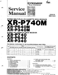
2. PANEL FACILITIES
ileglebalXil
-- ...,.. ..—. ...
—
L.....1.1...L.,..zL.
F -Q1
, ....
,
•
_
l'''7,7,777.ir7.7 .— = ..=._
-- —
..., ...—. , ..— ..
=•=e=•=•.=
_
mi
I
iii1=1
___
as, L__,
iiiiiiiiiiiiiiiiiiiiimii ME...1.-.7..'ilIFII°4'
I 8 EB 8
(7)
-....„
— —.
0 0 0
I
FM /
.—
_99./....— .9:4.,.../ 4.4‘....— Y-....
0 0
AMI Li Li.
AUTO LEVEL
L :VEL
0
IIIIIIIIII1111111111111111111111
o
POWER switch/Indicator
•
•
Press to turn power on
on
Press again to turn power off
e
n
MHz
kHz
I MONO
..... ..
I MUTING
r
13-24
.7
h
I
MEMORY
I- ..............
I HI Blend
PROGRAM I
........ .I- ISET
CHECK
I II
NEC
MANUAL:
Frequency changes by one step each time one of the
TUNING UP/DOWN switches is pressed. When the
switch is held depressed the frequency will mange
continuously.
— AUTO LEVEL indicator off
off
PROGRAM MEMORY buttons
Convenient for programmed recording.
ON/OFF:
Set to ON, and the three memorized stations will be recalled
in sequence as power is turned off and on again.
AUTO 1:
Press one of the TUNING UP/DOWN switches once.
The unit will automatically scan the frequency band
and stop when if finds a station (a too weaksig nal
station will be ignored). In this case use MANU AL
SET:
Press to set the program memory contents.
tuning mode.
j AUTO LEVEL indicator lights up
— ( •
CHECK:
Press to confirm the . program memory contents,
AUTO 2:
e
TUNING UP/DOWN switches
Use these switches to tune in broadcasting stations. Press UP
(+) to receive a station whose frequency is higher than the
displayed frequency, and DOWN (—) to tune in to a lower
frequency station.
Ca TUNING MODE switch
I
Tuning will stop at stations with more than nredi
signal strength.
— ( • ) AUTO LEVEL indicator lights up
urn
, AUTO 3:
Tuning will only stop at strong signal stations.
— (
• ) AUTO LEVEL indicator lights up
To select the tuning mode. It changes each time the switch is
pressed:
t9
MUTING switch
o
The muting circuit is designed to remove the typical FM
interstation noise generated when moving away from in-tune
frequencies, but it can also prevent reception of distant or weak
signal stations. In this case, press the MUTING switch off and
tune into the desired station. Normally, leave this switch on
(MUTING indicators lit).
This switch does not affect AM reception.
NOTE:
The setting of this switch is memorized together with the
station in the station memory.
o BAND selector switches
FM:
Press to receive FM broadcasts.
AM:
Press to receive AM broadcasts.
o
MEMORY switch
Press to memorize preset stations.
The [MEMORY] indicator will remain lit for about 5 seconds.
Press the desired STATION CALL switch to memorize it during
this period.
MEMORY
o
MPX (multiplex) MODE switch
Mode changes as follows each time this switch is pressed:
-0-STEREO:
For listening to FM stereo broadcasts (the indicator
lights up. when a stereo broadcast is received. The
indicator also lights, when a stereo broadcast is
received in Hi-Blend Mode.).
— [STEREO] indicator lights up
O
[1-12/13-24] Station call selector switch
Use this selector to choose between channels 1-12 and 13-24
when memorizing station frequencies or recalling already stored
stations. The [13-24] indicator lights up when channels 13-24
are selected.
13-24
I STEREO I
MONO:
To receive stereo broadcasts in monaural.
— [MONO] indicator lights up
MONO
-0- Hi-Blend:
Select this position when the stereo signal is noisy.
High frequencies will be blended, improving sound
quality.
— [Hi-Blend] indicator lights up
Hi Blend]
STATION CALL switches
•
Use these switches to preset stations and to receive already
preset stations.
O
Operation Display
0
Shows reception band and frequency.
•
When the TUNING MODE switch is set to AUTO 1-3, the
mark • above the signal indicator indicates the level set
for automatic tuning.
•
Signal indicator
0 Lights up when a stereo broadcast is received.
0 Stays lit while muting is occurring.
0 Stays it while the MPX MODE switch is set to MONO.
NOTE:
The setting of this switch is memorized together with the
station in the station memory.
o
•
Flashes when the REC LEVEL CHECK switch is set to on.
0 Stays lit while the MPX MODE switch is set to Hi-Blend.
0 Shows the condition of the program memory mode.
REC LEVEL CHECK switch
To set the tape deck recording level when recording FM
broadcasts. Press this switch on (the REC CHECK indicator
will start flashing), and an FM recording standard level signal
(frequency: approx. 330 Hz; level: equivalent to 50%
modulation FM) will be continuously delivered from the OUTPUT
jacks. Adjust the tape deck level meter reading to approx.
-2 dB to obtain an appropriate recording level. Always press
this switch off after setting the recording level (the REC CHECK
indicator will go off).
•
Stays lit while the PROGRAM MEMORY ON/OFF switat
is on.
®
Lights for about 5 seconds when the MEMORY switch i s
pressed.
0 Lights up when the station call selector switch is set to
13-24.
0 When a STATION CALL switch is pressed, it will show th e
corresponding channel number.
1
1
3
1
2
1
4
3,EXPLODED VIEW AND PARTS LIST
16
27
26
19
A
A
24
24
22 (X1/CA.HE,HB,SD/G)
35 (11E2 only)
22
Parts Li
30
17
Mark
No
24
(KU/CA and
Note:
When install the bonnet case and side board,
tighten the screw in ® to ® order.
22
14
25
22
Extern
15
13
RN1
RN2
•D
22
6--_
18
22
23
2
3
4
5
6
F- 91
NOTES:
• Parts without part ruimber cannot be supplied.
• The i mark found on some component parts indicates the importance of the safety
factor of the part. Therefore, when replacing, be sure to use parts of identical designation.
• For your parts Stock Control, the fast moving items-are indicated with the marks * *
and * .
* * GENERALLY MOVES FASTER THAN*
This classification shall be adjusted by each distributor because it depends on model
number, temperature, humidity, etc.
• Parts marked by "*" are not always kept in stock Their delivery time may be longer
than usual or they may be unavailable.
2 5E1560
2SB834
2SC2369
2SC2668
Typo No
—Lot No
Parts List
A\
*
A* *
Part no.
Description
1
2
3
1W7.1568
AWZ1570
ACE-501
4
0111043
TUNER assembly
AM assembly
Ceramic capacitor
(0.01J1F/AC250V. C409)
Power transformer (1901)
5
6
7
8
9
ASG-541
81101047
AMB1222
AAD1190
A8DI197
Push switch (POWER, S901)
Leg assembly
Panel base assembly
Tact knob B (PROGRAM MEMORY)
Power knob (POWER)
10
11
12
13
14
011111029
AA111298
011111300
0011001
AAP1064
Aluminum sash
Acrylic panel
FL filter
Name plate
Side sash
15
16
17
18
19
AMR1160
0115I015
01151016
011111128
A11E1087
LED lens
Side board L
Side board R
Front panel
Bonnet case
20
21
22
23
24
0881033
AEC-093
004-298
ABAI006
111)81009
Screw
Screw
Screw
Mark
No.
kn-'A38 a; &8N81
No.
Mark
Part no.
Description
4841011
ARA1032
AN-088
88226P0813FMC
FBT40P080FZK
Screw
Screw
AC power cord
Screw
Screw
VM230P060PCD
AW21576
AW21577
AWZ1580
AWZ1579
ABA1035
Screw
BET VCO assembly
IF VCO assembly
FRONT END (1SC assembly
IF MODULE assembly
Screw (REZ only)
2SC2786
2SC2878
LC7570
2
Type No
145218P
101
102
103
104
105
FL assembly
SW assembly
REMOCON assembly
Chassis
Rear panel
106
107
108
109
110
Transformer frame
Front panel holder A
Front panel holder 8
Earth lead
PCB holder
111
112
113
114
PCB support
Shield cover
Earth lead
Earth leader
t(PC11638
APC781405H
LA1247
Typo No —
Lot.
Coil spring A
Binder
NJN14868
PA5008
PA5007
P 00 1
CX-7525B
P05056
External Apperance of Transistor and ICs
2 SK2 41
2SK161
2SC2603
2SA1115
RN1203
RN2201
2SJ103
251(246
Trneno
"'PPP
Lot No
La
Lot No
Lot.
7
9
2
F-91
1
3
4
5
6
4.GCHEMATIC DIAGRAM
AW7 t567 I HE, HB1
TUNER ASSEMBLY AWZ15613 1.6U/CA
AVIZ 1569 1SO /0
AWE 1666 IHE 2/
iF MODULE ASSEMBLY
■111
04.5
.me ME. ASSAY, MeMe
.333
A
10.
17,1
MN*
tar
Afeffmm
!bale
P.
AWV579
IMRE
11111r
: : 1PM
gaol
gig
41'
•
Men
11.11111.1.111MOMMINIMMIA
I M■iliMM
373.
05 LBT1
Pal
a
Inn
Eilat.t-1 .
GD
161.66
AM ASSEMBLY AW2 1570
—
1:73'
M
mat
IF
PI' In.
"
t'61:
IT
11.0
.: 1.11111
=MN
MNMIMI=
=WM
intl%11
ohs WILIIPINIET
2-
IMINIM
■ EMU=
Olti2
■11111i ••••••1
11■ 1111
9
BROMISM
REMOCOV66,....
7; OW/CA 1061020/6 1
110111fign
akt
•
r
ADE
"itil
_
0,0
3
:
IMM
af re a rEUIMEINE
■•■
.-
e
04dla
=se
IM •=111111= •
11
■ I•
11111• ==11
r
2
MIME M.
Ni/MO
IEiI
0 ED 01110
3
4
= M
im
a salmi
■
.481.0401 ,
KM6101.
••IMM■1
W
mwraellp.7ATIR
toe!viniiim
r,
1
60
9
Mil liikano
E REIIEWIM
M
MMEENIM
mins=rea
=
M
MEM on.
3,0
I
eVFE;
"
LL_
"I
A.W7
,, 15 7 7
Owl NM
" Low=sa
li l
r.=
1 iii
-'2
MOO ASSEMBLY
0106 66166 GAO
womplim eimai.lr ,.
1 pa V
E....mina3/4
01
mi
:16611
31:
A10, if Me
1
5
6
I
6
0 I.
14
11111
1111
a
34.11 238 80i
aniumnagal
e+g:-;.•
3 "111•101-- 50 1111,01.1 I
a 0,
9.igarna A-1136135SO
IIMMEMINMEM
wimmocilmi
Immiommi
cmec.imel
IRMIDDI ■1
sime
.g.ra
5300. Om al. 30 (150
ull•miiMMErmin
mo9.IMPIETNIMIZO MI
INDMilutialimi
41-
iminumis
MO
Mal
M.
OM
MN
.11.1
111.1 ES MN
ir. nem=
Nemm
il•ININM
A
frE
A 816355V .5
LE=3 6.0
10,0011
INIMNM ■1
01.
11111.11111
11551 585,11,11-71.
1,0181
1111
%MI6
111•01.010(1
111X1611
111”
361A1. 0 /05 60,
03n J.
03A
MEM !
=
inatems
g •'11 I :1
51
11185•LOVI
.565
""'-"
' ' 11:.56(708•1111•0811
IAMB: MIS
120561L
1■10.6.
MEM
141
Ermommannam.
1061
(AVM 5/01)
19160
110121125 170 8•11810
18.1.1-1,11/3
r (13 Al: 21213
21101"-'1051
800 mar 2141:
tta
111 ■ 1 40 (141 631310 - 3
501- 21.0
r
1813 SUS
MUNI WI
8111.1111/5
018 111181/ 180
0,11 :111S
13.111 'WS
9
1.11.0111.
680100
11151„.
110
1:3■'11''01111101.141-
1054
MIND
MEM
ummom
W'''' ''''11115•511050.011I/981
1121
1112-112101-.111.
80,614
(111210
L2.
1 03 01 -MA
Pt • 0 711
Itf111
LiE.St1
OM .111
ILA.
f
710 1011.1 11/1 9.3
t
NEN
I.19
661.10111
11811-1
SUSI
ODOM 3111816111.1 105.06
MB
mo
hi. •
150501
811.1
51/11100
Mal LOB
11/1 .1. MS
Alms. its
111551
151-1.
1118311.
MI- INV
-1611
I/Xlig;V
801
1613511
181
[OK.
1-61,91
19606111
11110511
101381,00
1.61110, (0 - 501160
szm ral
MK- 1.-42L -KI-A111.13/
VIM 813.1211157/110111828
w
A-18.355V
110111
”1 ::: I - %Pil l:
illICIRWC- EMCGMEEN
100 LW 311116.1.111000 1 1110180
.
1-18.
111011914 1101. 440 SOWN, /.11.01. ,
,a.•
ar,
1111A
alp., a!, , ar saaa
■
gm. co,* .60 68
•1018. .1.1 O..
001000
6. sopa,. sa... .0.00
pima ,ra
0.11.1,•a0
,st,a t
MOW lr
EPD
98/16111:031 ..01. 1.111
ca
ZOg
101
015
,
I
5110
7,1,1
11..
M.21INS 011. -
110680 18.1161
al .01. 1/.00 100•00., 'see
1.01 0100. 000 00 0600.00 1.166.6 611.1.110
:8•3313.81
. •••••••• ■ •17aS.
723 640 .11,0) 11080 '06 16
1606 16 0606
1.10 6660.0 153 W. 8. WI 701 •16 0.0116!
:Matti .1 •
■
,a MI 370.43
asu, g
aaa, aaa, ,
g
,
.0.165 0100 01
01
I1170
MOM
916711g
3
5.P.C.BOARDS CONNECTION DIAGRAM
4
1
0410 0'441' 12 10401
B401
(1.011 ■ BIS0
-
QZ05
Q305
0107
.30f "441■ 309 71120.3
0106
■ 0105
10502 aiti " :10 ,1 110 1
002321
0302
.3
, c1011
D103
.D104
0 1 09
Q304
4 ,101
11,1031e104
Ic106
:DT
0101 4102
ICIO1 10102
04
Ion
ve101
OS 03
0402
1
2907
06
:550" "5"
nr:
DR,OZ
AtiiriIND
A
6
1
Aill1568 gli/CD) DAMES DEW
MB ASSEMBLE ADZIHT (KEA SAME, (SDID)
0210 ""4 7D 13
0409
5
Ase,
r
BONED
e7e:
071202
COnz
IF CO ASSEMBLY (All
L_ —
Dfl BED ASSUBL! (AIM
*Tv.
-..;*
DEMDCON MEDIU
aDIC A AND SEIM
4
FRONT
soxiltot,
e
4 FRONT
•
IF NODDLE ASSEMBLY (071519)
10002
DB01- DBOI
I C.01
FL ASSEIIBLI
1
2
3
4
5
6
Fr".
5
4
1
6
1
I
8
1
1
F - 91
1) WIFE (EU)
181 01215SA (SDIB)
: 2 01
U101 "
RR
"gt
0106
I'Ll'01 ""
''" 1[10P "
J[105
0103 .104
1.102
WRID6
v 103 R104
v
VRIC7
1[106
0103
0404
CIDI 0102
.101 .102
IC.3
61401
Ve1111
I. 03
04
OS
05030502
0501
0407 IC501
*'
/711 DE-C14,14.515
A
*Note 03-4 is the FRONT END OSC ASSEMBLY and
03-1 to 03 - 3 in the TONES ASSEMBLY are
used the even characteristic Paractor.
Therefore, when the FRONT END OSC ASSEMBLY
is replaced, replace 03 - I to 03 - 3 in
Site TUNER ASSEMBLY together.
Use 03 - 1 to 03 - 3 so that 03 -- I to
03 - 3 as even characteristic as r8 - 4 are
instal to in the FRONT END DSC ASSEMBLY_
,
NOTE
. Thn P C connect.on degrein is veered IrtNn the parts mounted a..
. The wen MINN neve been mount. on NS Powd can be replaced ww, whom Rhovwn
WIt, the torreepond, wiring symbols Wed in Om folleenna Table.
VCO ASSENBLY (11F1517
FGR 7C1/5
5FJ
FRONT EID ESC ASSEMBLY (ABI190)
or Likl
F "O' .
_
-pri..r[g-1
TN....
Radial., tyre
trensittor
02.05 --.
—,
0-- 14--.
[No.
R23/
O-4ND--0
Pairtor
Ca...,
IRoYeityl
05,5 )O
BET VCO ASSEMBLY (illi1576)
iNononladtgl
PC., og ee,
Part N•me
IC
IC
Switdv
4
FRONT
RY
ReNe
va
Varied. restate. of
Sew-urea mato,
Fihar
a The...awn. orminw ...ad ...Owlet,. aim.) show, negate.. terminal.
. Th5 cliock terminal merit. with C)
,.thee. ed.
S. The trunistor terminal to which E effixed than the •TItNN.
Si ASSEMBLY
.....
F NOBBLE ASSEMBLY (ANI1578)
I CRO1
4
5
1
6
7
1
8
1
9
1
8
1
a
a
(IX 332IIIIA (A3
223(11A (811
(0T2AS1A) rJ322A A
ea
SOU
A
i - E0
bna YJIM322A MO GI 1110119 sib n
sac Y..10922.11 VS4UT sr11 pi
C - Es
I oil*
AO
re
Al
LC10
MAO
SO I,
r
.10.3.
SOAA
!OA
All or, B01. LOCO SOCA
norni
tet71
1.0111 °
ACM/
141. 1v
10
"
SO IAA
10.1AA fOtov
A0
PK:
'1/1?It
aiolABIA
.talDalav 31/a Itabs1.3 novo st1J bozu
.2.411•113-al NIA
YJ8t1.322A 320 (313 TNOffi off! nerlo .snolsnorIT
niS-EC
sos loon .bsool non zi
,sd1s3oJ YiEt322 ■1 CPU1 on!
on I -EC
on
P —ea
1 --E0 lull on E -EC
ens
on I - EU set/
es ainzinsloolado tynvo
E- EC
.1%IfitI322A 320 CIE 1110g9 otit n i by I Inn zni
3100/
enn000n, noon er11 molt
nao. v.*
ei
.61" mon. . ni basea
...11 nag
...IT
A.A,1 lor.A.1
loft an./
....1
......1
IrOnooni
Ma■I
norramnoa 7.9 cirri" .1
Barak.. raa Insod. no bemworn mad and dara Ansa .7
laranw rag Pra....aaJ
IVO on,enoca..a arn
A,
rgrEl rff-
TIC'
0
0
ALTA
ABA
0
(2:r
(OON) 1.11113122A 320 013 11093
17, '0 '
)
c7-
"SC-
0
d
veob
41_0
iio n 11
1.14122A larlti7 ABA
'7'03
rtKfiK
0
(T7213
noire.. may., ...A.A.,
/
(MIA) 1.111132A ON 130
Iyonsion-onr0
e1.0
mapsila
amsir
....9
ra1nre
TS
ray,
4
vo
arlshaV
Ara.. Baal...
Ti10511
ler .0
anat., aro.. rm.. to., ..111ii40..
era
Asa*. ear. bawl's al 3 rlarlw Wm.. Aorarn.."1"
""--:
21211323A 03
°
VIM/ 112132ZA 3.1010A AI
131
I
8
a
a
2
1
3
MM
IC 801
ICOOS
IE 11111IrE V22EIGII (Us)
°
7■
I
waitiloo
-
EOILL
oat.
1.
TolNyunw
ymin
.1100111
■111
0C1i00
OM.
2d101 :
4'
04.1.11:
ICOMP
WV DE
:201: mower
AMC
V:LE
101I:C7.00
0001
/114.00
MC
%IA
olS02
//COE 00SPV
011003
111S00
mil 03 nolOP
MOOS
DSO:
C POI
awn Me
2 . 1) . C . BOVI5D2 CONNEMON DIV1ft61191
' :700
ourmwucHom rcao,v
woocr) MIghhE
00101
0¢1100
111303
0303
0108
1C10.1
030P
ABACI
1:103
0.01
ItIPC
1C/01 1CIOS
0101 010S
0,
04,
1
■0■■
0 OS 10201
0201
OM 0200
O7
03
F-91
6.ELECTRICAL PARTS LIST
TUNER Assembly (AWZ1568)
NOTES:
• Parts without part number cannot be supplied.
• Parts marked by 'Cr are not always kept in stock. Their delivery time nay be longer than usual or they may be
unavailable.
• The th mark found on some component parts indicates the importance of the safety factor of the part. Therefore,
when replacing, be sure to use parts of identical designation.
• For your parts Stock Control, the fast moving items are indicated with the marks ** and 4c.
** GENERALLY MOVES FASTER THAN *
This classification shall be adjusted by each distributor because it depends on model number, temperature,
humidity, etc.
• When ordering resistors, first convert resistance values into code form as shown in the following exanples.
Ex.I When there are 2 effective digits (any digit apart from 0), such as 560 ohm and 47k ohm (tolerance is shown
by J=53, and K-107.).
5600
50(10'
561
RD1/4PSCO1061OJ
47x105
473
47ka
RD1/4PSEOCLICEJ
0.50
ORS
RN2111118803BK
010
RSIPITOIDOEK
Ex.2 When there are 3 effective digits (such as in high precision metal filn resistors).
5.62kf1
562)(10'
5621
RN1/4SR10J83[2120F
FL Assembly
Miscelloneous Parts
Mark
Symbol & Description
Part No.
REMOCON assembly
FL assembly
TUNER assembly
SW assembly
AM assenbly
0821568
DET 1/CO assembly
IF VCO assembly
FRONT END OSC assembly
IF MODULE assembly
A1421576
AW21577
0821580
0821579
SEMI CONDUCTORS
Mark
Symbol & Description
**
**
*
*
Part No.
IC801.1C802
0801 - 0809
LED (POWER)
0801
0802 -- 0813
LC7570
RN2201
AIL-45I
ISS131
AWZ1570
SEMI CONDUCTORS
Mark
Symbol Z Description
**
**
**
**
**
**
**
**
****
**
**
**
**
**
**
**
****
**
**
**
**
SWI TCHES
Mark
**
Symbol & Description
Part No.
S801 - S803 Tact switch
rPROGRAM MEMORY (CHECK, SET,
A56-711
)
'ON/OFF)
C409
/h
1.511
* 1901
th** 5901
th
Ceramic capacitor
(0.01/01:2500)
Loop antenna assembly
Power transformer
Push switch (POWER)
AC power cord
ACE-501
RES I ST OR S
ATB-086
0111043
ASG-541
ADG-088
** 0603
** 0601,0602
*
sal
Part No.
RNI203
2SC2603
ISS131
Symbol & Description
Part No.
R601 — R604
RD1/8PM103J
OTHERS
Mark
Symbol & Description
2P Mini jack (CONTROL)
22
Part No.
0801
9802 - 9811
R01/4Pre21J
Ro1/8pno a !DJ
Hark
RESISTORS
Mark
Symbol & Description
OTHERS
Symbol & Description
REMOCON Assembly
SEMI CONDUCTORS
Mark
Symbol & Description
Mark
Part No.
AKN-209
*
1/801
Fluorescent indicator tube
Part No.
AAVI025
*
*
*
Part No.
Mark
Symbol 1 Description
Part No.
THI03-2
CK-792513
n5218P
NJM1496D
PA5007
1103,1109.1.110,1122
Axial inductor
L112 Inductor
1113 Inductor
F101 FM Ceramic filter
LAU3R9K
LTA223J
LTA472J
ATF-I18
IC102,1C108.11:201
10502
1C1131, IC105 — IC107
1C401
03
P05008
pD5056
10C116311
PPC78MOSII
P001
F103,F104 FM IF filter
F105,F106 Ceramic filter
F102 FM IF filter
11
FM RF transformer
13
FM Balun transformer
ATF-139
ATF1024
01F1025
ATC-204
ATC-2I8
CI:
C4
C51
C2
0101.0105,8402,0404,0412
(1102,0104
0403.0501
0401
0406,0409
RN) 203
0112201
2SAI115
2S13560
2S13834
1104 FM Matching transformer
12
FM IF transformer
1103 FM Detector transformer
1101,1102
FM Matching transformer
ATE-063
ATE-066
ATE-068
ATEI004
C4:
C4(
Cl!
0205
8302-11304.0407,0408,11410,
0411,0502
0103
04.05
2SC2389
2562603
2SC2668
2SC2786
0106.0107,0202.0203
0201
08.0108
0204,9209,0305.0405,0503
0411
2SC2878
2SJI03
2SK241
2SK246
0256625
1)400,0410,0416
0408
11,107
0418
05
11259031.
1111131111
ROISEB
18101,111201
18501
16363
1C103, 1C104
16302
Thernistor
RD2.2ESB
007.5118
RD8.2ESB
908.2F8
55566
1SS131
0101.0102
0401 - 0406
0103,0104
15585
IODF2FD
2-11(261
12
LI
1.501
1203
1.204
Sy
CS
C5
CL
C2
CL
CA
Ca
C21
1)419
0203,11204
0412 — 0415, 11417, 11506
04,0201,0202. 8302. D303,
D501 — 0505.0507,0.508
COILS. FILTERS
AND TRANSFORMERS
Mark
Symbol & Description
Bark
Part No.
FM RE Coil
FM ANT Coil
Inductor (IWO
Coil (38klix)
Coil (191dU)
ATC-205
ATC -244
ATH-098
ATM-026
8111 -028
1105,1107 Axial inductor
1102.1104,1106,1108.
1.115 -- 1117,1123,1124.1201.
1205 Axial inductor
1101,1111,1114.1.121
Axial inductor
LAU010M
1.0620211
LAU22IK
CAPAC I TORS
Mark
Symbol & Description
Part No.
TCI --TC3 Trimmer
6344 (390p/DC50V)
C1 -- 05,C9,C11,C13.C14,C21.
C22,C28,C37 --C39,C101,C104,
C127,1:130.1:137.C145,1:168,
C169,1:184.C190,C191.1:201
1:267,1:268 (0.01/01:251/)
634
C21
ACM-018
ACG-023
01:6 -036
C4(
C2I
CIE
C18,C27,C102,C103,C105,C106,
CI08.C120.C121,C123,C124,
C128,C129,C131,C134
C138 -- C144,C162,C163,
C165 -- CI67,C170,C171,
C173 --C175,C177,C1 .
C202 -- C204.C209,C211.C220,
C231,C250,C261
(0.047/00251/)
ACG-037
C4C
C2C
C17
040
C21
(47000P/5.5V)
C5I8
CI85
C186
CI87
C132.6369,C419,1:521
ACH1011
CCCS1.010C50
axsukl0c50
CCCS1050C50
CCCSLIOIJ50
C182,C183
C160
CI26
CI33
C12
CCCS1181J50
CCES1221J50
CCCS1271J50
85CSL390J50
CCDCH010C50
C23,C24
C508,C513
8512
C519,C520
C8
CCDCH030050
6600HI50J50
CLOCH220J50
CCDCH270J50
CZDCH470J50
C25,C26
C6,C7
C15,C16,C19,C210
6333
CI7
CCDRHIOJJ50
C22
C22
C15
632
632
ccosH050c50
CCDSH150J50
CCDSLIOIJ50
CCDS1820J50
C23
C32
C20
044
C4r
C33
C50
CZX
633
c154
C15"
C211
C22"
CI6)
635
6341
C241
c26:
caK
TUNER Assembly (AN21568)
SEM I CONDUCTORS
Mark
Symbol & Description
Part No.
Mark
Symbol & Description
Part No.
TH103-2
CX-79258
115218P
NJM14961)
PA5007
1103,1109,1110,1122
Axial inductor
1112 Inductor
L113 Inductor
F101 FM Ceramic filter
LAU3R9K
LTA223J
118472.1
ATP- 118
** IC102, 1C108, 1C201
** IC502
.** 10101, 1C105 - IC107
** 10401
03
PA5008
PC15056
ii PC116311
PC713/105H
P001
F103,F104 FM IF filter
F105, F106 Ceramic filter
F102 FM IF filter
T1
FM OF transformer
13
FM Be I un transformer
ATP- 139
ATF1024
ATF1025
ATC-204
010- 218
' ** 0101,11105,0402,0404,0412
** 0102, 0104
** 0403,11501
** 0401
** 0406, 0409
001203
0112201
221115
22560
258834
T104 FM Matching transformer
12
FM IF transformer
1103 FM Detector transformer
1101,1102
FM Matching transformer
ATE-063
ATE-066
ATE-068
ATE1004
** 2101, TH201 Thermi s tor
** 1201
** 10203
** IC103, IC104
** 1C202
**
** 0205
** 0302 - 0304,0407,0408, 0410,
0411, 0502
** 0103
** 04,05
2S2668
2SC2786
** 0106,0107,0202,0203
** 0201
** 08,0108
** 0204, 0209,0305, 0405,0503
* 1411
2502878
2SJI03
22241
22246
1126C2L
2SC2389
222603
*
*
*
*
*
11409,11410,l1416
0408
0407
11418
05
1129A3L
11013118
12015611
8(12. 20S8
5118
*
*
*
*
0419
0203, 0204
0412 - D415, 9417, 0506
04, D201,0202, L1302,1)303,
0501 - 0505. 0507, D508
1108. 20S11
1208.2PB
2566
ISS131
11101, 1102
0401-0406
0103, 0104
1SS85
100F2F0
2- 10201
*
*
*
COILS. FILTERS
AND TRANSFORMERS
Mark
Symbol & Description
Part No.
L2
FM RF Coil
LI
2 ANT Coil
1501 Inductor (110
1203 Co; (38kHz)
1204 Coil (19kHz)
ATC-205
ATC-244
ATH-098
ATM-026
ATM-028
1105,1107 Axial inductor
1102,1104,1106,1108,
1115 -L117,1123, 1124,1201,
L205 Axial inductor
L101,1111.1,114.1121
Axial inductor
LADOIOM
LAU2R2M
1811221K
CAPAC I TORS
Mark
Mark
RES I STORS
Symbol & Description
Part No,
0501
0502
C179,C192,C206.0332
0243
C159,C242,C246,C247.C416.
0418,0214
CEANL2R21150
CEASI1471450
CEAS0101150
CFASIR5M50
CEASIOOK50
C125, C511
0414,0415
204
C214, C249, C330, C421 ,C505
C122
CEASIOIMIO
CEAS1011116
CEAS1011135
CEAS2201125
CEAS2211116
0410. 0411
0402
C181, C334, C336, C408, C420
0262
C212, C401,0412, 0413
CEAS222M16
CEAS3321135
CEAS4117/150
CE854701110
CEAS470M25
CEAS6181150
CE0A2221116
CEX84711150
CEYANP3R31150
CEYA1011116
Symbol & Description
Part No.
TCI -TC3 Trimmer
0244 (390p/06500)
Cl - C5, C9, CI I . C13, C14, C21,
022, C28, 037 - 039, C101, C104,
C127. CI30, C137, C145, C168,
C169, C184, C190, C191, C201
C267, C268 (0.01/06250)
AC11-018
ACG-023
008 -036
0245
0251
0404
0217, C2I8
C189
C18. C27, C102, C103, C105, C106,
C108, C120. C121, CI23, C124.
C128, CI29, C131, C134-C136,
C138 -C144, C162. C163,
C165 - C167, C170, CI71,
C173 -C175, C177, Cl
C202-C204, 0209, 02I 1 . C220,
0231,0250,C261
(0.047/0250)
ACG-037
0406,C407
0205,C260
C176
0403
0210, 0219
CEVA 1011150
CEYA] 021416
0E0A2211116
CE082211150
0000222096
0221, 0222, 0234 , 0235, 0237, 02313
0225 , C226
C156
0327 - 0320
C325
CFYA4R7M50
CFTXA103J50
CFIXA104J50
CFIX9123.150
CFI11A223J50
C518
(47000P /5.5V)
C185
C186
0187
0132, C269, 0419, 0521
ACHI011
0:(21010050
CCCSL030050
22105020
CCCSLIO1J50
0236
0326
CFTXA333J50
CFTXA473J50
CKDYF102150
CKEIVF103150
CODVF2237-50
C182, C183
0160
C126
C133
C12
07051181.150
CCCS1221J50
CCC2271J50
CCCSL390J50
CC0C11010C50
023,024
0208,0513
0512
C5I9, C520
131
070611030650
000611150.150
000611220.150
025,026
08,07
C15, C16, C19, C20
0333
C17
Mark
*
*
*
*
*
*
*
*
Symbol & Description
Fart No.
1/8106, 012202 Semi-fixed (toO))
VR103, VR204 , VR205
Semi-flood (10k t2)
V8102, VR104. VR201
Semi -fixed (100k 12)
V01560S102
0111S605103
VRTS6VS104
141101, 011203 Semi-fixed (220 S2 ) VRTS6VS22I
011107, VR206 Semi-fixed (2. 2k II) 081S60S222
011207 Semi-fixed (MD)
0RTS60S223
VR208, VR209 Semi-fixed (220k Q) VR1568S224
00302 Semi-fixed (47k D )
0R1S60S473
R408 Carbon conpos i t ion
resistor (2. 211/1/2W)
11527, 11528
Resistor array (10k x4)
0526 Res is tor array (10k x 5)
11206, R207, R210 - R213,
8216-- 0235. R237, 122,38,
0240- 8243, 0258, 11261
1234, R250, 0401
RI 1 , R20, R236
8208.11209, R214,12215,11248,
8403,0404
R420, R421
0409,8422
Other resistors
ACN-209
RA4SI03.1
RA5S103./
R001/4P010 00.1
lll1/2FMO 00.1
21/4P110 0 0J
RN1/4P0 0 0 0 0F
RSILMF181.1
RS21.11F 0 00.1
011/819100 0J
OTHERS
minimum
C00011470J50
CCDRI1101J50
000S11050050
CCDSI1150J50
06051101,150
06051820.150
0208. 0509
044.C170, C180. 0335, 0506
0417
231, C405, 0507. 0510, 215. 216
0,503
0225,0224
0232,0233
0158
CKDVF47320
C000103J50
CIIMXA102J100
COMXA182J100
CIIMXA202.1100
C157
0215. 0216
C227.1'228
C161
C229,0230
00OI38222.1100
C011)(A242J100
C0808272J100
CO1C(A362.111)(1
COMXA472J100
0248
0241
0263,0204
0239,0240
0058682.150
CO2821150
00SXL331J160
0IIS18561J160
Mark
*
*
Symbol 11 Description
Fart No.
12502 Ceramic resonator
11501 Crystal resonator
2P Fin jack (OUTPUT)
2P Push terminal
ASS-030
ASSIDO9
01(01031
AKE-060
SW Assembly
SEMI CONDUCTORS
Mark
*
Symbol & Description
Part No.
D702,0703, D705-11708, 0710
105131
SWI TCHES
Mark
Symbol & Description
Part No.
** 5701 - 5718, S720 -S723
82-711
Tact snitch
STATION CALL, TUNING (UP,
DOWN) , 1-12/13-24 MEMORY, BAND
(FM, AM). TUNING MODE, MUTING,
IIPX MODE, RE LEVEL CHECK
F-91
AM Assembly (ANZ1570)
SEMI CONDUCTORS
Mark
Symbol & Description
** IC301
** 0301
* 0301
* 0304, D305
* 0306
* 0307
Part No.
LA1247
2SK246
KV1226
1SS131
RD5.1ESB
HZS5CLL
DET VCO ASSEMBLY (ANZ1576)
IF VCO ASSEMBLY (AWZ1577)
*FRONT END OSC ASSEMBLY (AWZ1580)
IF MODULE ASSEMBLY (AR1579)
There are not supplied parts above four
assemblies.
CO I L, F I LTER AND TRANSFORMERS
Mark
Symbol & Description
Part No.
L301 AM OSC Coil
F301 AM Ceramic filter
1301 AM Antenna transformer
1302 AM IF transformer
AIR- 073
ATF1004
AIR-087
ATB1002
CAPACITORS
Symbol & Description
Mark
Part No.
TC301
TC302
C304
C309
C306
ACM-019
ACM-020
CCDUJ100050
CEAS010M50
CEAS100M50
C317, C320
C311, C312
C32.3
C324
C316, C318
CEAS330M16
CEAS4R7?150
CFTXA103J50
CFTXA473J50
CKDYF102Z50
C307, C308, C313, C315, C321
C310, C322
C302, C314, C319
C305
C333
CKDYF1037,50
CKDYF2237,50
CKDYF473Z50
COSA431K50
CCDSL101J50
RES I STORS
Mark
Symbol & Description
* VR301 Semi-fixed (22k12)
Other resistors
*Note :
03-4 in the FRONT END OSC ASSEMBLY and 03-1 to
D3-3 in the TUNER ASSEMBLY are used the even
characteristic varactor.
Therefore, when the FRONT END OSC ASSEMBLY is
replaced, replace 03 —1 to 03-3 in the TUNER
ASSEMBLY together.
Use D3-1 to 03-3 so that D3-1 to 03-3 as
even characteristic as 03 —4 are installed in
the FRONT END OSC ASSEMBLY.
Part No.
YRTS6VS223
RD1/8PM0 U ELI
OT HERS
Mark
Symbol & Description
* X301 Ceramic resonator
Part No.
ATF-125
25
F-91
7. ADJUSTMENTS
AM Section Adjustments
• Wire as shown in Fig. 7 I
• Set the AM key to ON and the REC LEVEL CHECK key to OFF.
-
AM SG
(400Hz, 30% de modulation)
Step
Frecuency
Level
Adjustments
F-91
frequency
Adjustment
point
Standard
530kHz
1531kHz1 •1
L301
Adjust so that the voltage between terminal 33 and ground
is 2V (± 0.3V).
1,700kHz
(1,602kHz)"
TC301
Adjust so that the voltage between terminal 33 and ground
is 24.5V 1±0.5V1.
indication
_
1
No signal
2
3
Repeat steps 1 and 2 until both ground voltage standards are satisfied.
4
Mechanically set VR301 to the midpoint.
5
6
7
B
600kHz
(603kHz)•1
50 — 80dB
600kHz
(603kHzr 1
T301
Maximize the voltage between terminal 35 and ground.
1,400kHz
1,400kHz
TC302
50 — 80dB
(1,395kHz1 •1
(1,395kHz ) "
Repeat steps 5 and 6 until the maximum voltage standard is satisfied in both steps.
600kHz
(603kHz1 •1
100dB
600kHz
1603kHzr 1
VR301
Adjust so that the voltage between terminal 35 and ground
is 4.9V (±0.1V). •2
'1: The frequency in the parenthesis is the frequency at 9kHz STEP (HE and HB types').
*2: Do not let the voltage of terminal 35 exceed 5.2V.
FM Section Adjustment
Note: The adjustment method of this FM section is simple throughout.
• Wire as shown in Fig. 7 2
• Set the FM key to ON, and the EEC LEVEL CHECK and MUTING keys to OFF.
-
Stec)
FM SG
(1kHz, ±75kHz deviation)
Frequency
Level
1
Adjustments
F-91
frequency
indication
Adjustment
point
Standard
108MHz
L3
Adjust so that the voltage between terminal 33 and ground
is 23.5V ( ± 0.2V).
No signal
Confirm that the voltage between terminal 33 and ground
is 7,5V (± 1,0V).
87.5MHz
4
5
6
90MHz
40dB
90MHz
L1, T1, L2
106MHz
40d13
106MHz
TC1—.3
Maximize the voltage between terminal 22 and ground.
Repeat steps 3 and 4 until both ground voltage standards are satisfied. Terminate the adjustment with step 4.
106MHz
60dB
106MHz
T103—a
98MHz
18dB
(Stereo
modulation)*
98MHz
VR103
98MHz
40dB
98MHz
Set the REC LEVEL CHECK key to ON.
—
VR302
Sat the voltage to OV for terminal 24 to 26.
Adjust to the point just before muting is applied.
Check the output level of the output terminal.
At step 8, set the output level of the output terminal to
—6d8 (± 1dB).
• Stereo modulation: Main 1kHz, L-R, ± 68.25kHz dev. pilot 19kHz, ± 6.75kHz dev.
F-91
AM antenna terminal Output terminal
Oscilloscope
AM loop antenna
1
AC voltmeter
Digital voltmeter I L—I
Fig.7-1 AM adjustment wiring diagram
I
Frequency counter
— — — — —I Digital voltmeter 1
Oscilloscope
300 ohms dummy
FM 75-ohm antenna terminal
AC voltmeter
F-91
Output terminal
with matching unit)
Fig.7-2 FM adjustment wiring diagram
AM assembly
ii
OUTPUT
Cart
1302
;
0.0
TC302
TC301
VR301 001
/
vo)
11
e
TC22 411:1
•
25'1'
26
•
TC1
/IP
34
•
35
23 VN103
1103
24—*
Vs
Li
1301
VR302
TC3
100
L2
00
0
••
0
L30 0
Fig.7-3 Adjustment point
27
F-91
7. REGLAGE
Reglages de la Section AM
• Effectuer le cablage comme indique sur la figure 7- I.
• Enclencher la touche AM et clesenclencher la touche REC LEVEL CHECK.
Etape
AM SG
(400Hz, 30% de modulation)
Frequence
Reg'ages
F-91
indication de
Point de
reglage
Norma
530kHz
(531kHz1 •1
L301
Regler de telle maniere que la tension entre la borne 33 at la
terre soit egale a 2V (-± 0,3V).
1.700kHz
11.602kHzr 1
TC 301
Regler de telle maniere qua la tension entre la borne 33 et la
terre soit egale a 24,5V (± 0. 5V).
frequence
Niveau
1
Aucun signal
2
3
Repeter les etapes 1 et 2 jusqu a ce que les deux normes de tension de terre soient satisfaites.
4
Regler mecaniquement VR301 a mi-chemin.
5
6
7
8
600kHz
(603kHz)•1
50 - 80dB
1.400kHz
(1.395kHz) •1
50 - 80dB
Repeter (as etapes 4 at 6 jusqu
600kHz
(603kHz)' 1
100dB
600kHz
(603kHzr 1
a
T301
Regler de telle maniere que la tension entre la borne 35 et la
terre soit au maximum.
1.400kHz
TC302
(1.395kHzr 1
ce que la norme de tension maximum soit satisfaire dans les deux etapes.
600kHz
(603kHz)' 1
VR301
Regler de sorte qua la tension entre la borne 35 at la masse
soit de 4,9V ( -±0,1V). •2
"1: La frequence entre les parentheses est la frequence a l'intervalle de 9kHz (modeles HE et FIB).
*2: Ne pas laisser la tension de la borne 35 depasser 5,2V.
Reglage de la Section FM
Remarque: La methode de reglage de cette section FM est simple du debut jusqu'a la fin.
• Effectuer le cablage comme indique dans la figure 7 2,
• Enclencher la touche FM et desenclencher les touches REC LEVEL CHECK et MUTING.
-
Etape
FM SG
(1 kHz, ±75kHz de deviation)
Frequence
Niveau
1
Indication de
frequence de
Reglages
F-91
Point de
reglage
Norma
108MHz
L3
Regler de telle maniere qua la tension entre la borne 33 at la
terre soit egale 6 23,5V ( -± 0,2V).
87,5MHz
. . .
Aucun signal
2
4
5
90MHz
40dB
90MHz
L1, T1, L2
106MHz
40d8
106MHz
TC1 -3
Verifier si la tension entre la borne 33 et la terre eat egale é
7,5V (-± 1,0V).
Regler de telle maniere qua la tension entre la borne 22 at la
terre soit au maximum.
Repeter les etapes 3 et 4 jusqu'a ce qua les deux normes de tension de masse soit atteintes. Parachever le reglage avec l'etaP*4.
6
106MHz
60dB
106MHz
T103 -a
7
98MHz
18dB
(Modulation
stereol•
98MHz
VR103
98MHz
40dB
98MHz
Enclencher la touche REC LEVEL CHECK.
VR302
Regler la tension stir CV pour les bornes 24
a
26.
Regler au point situe juste avant que l'assourdissement
n'entre en service.
Verifier le niveau de sortie de la borne de sortie.
A l'etape 8, regler le niveau de sortie de la borne de sortie
sur - 6dB ( -± 1dB).
----...
• Modulation stereo: Principale 1kHz, G-D, 68,25kHz dev. pilote19kHz, ±- 6,75kHz dev.
F-91
Borne de l'antenne AM Borne de sortie
Oscilloscope
I
-
Cadre AM
Voltmetre de CAI
Voltmetre digital
Fi9.7-1 Diagramme de ablage de reglage AM
Frequencemetre
r— ———
MPX SG
1
FM SO
1
Voltmetre digital
Oscilloscope
Charge artificielle
fictive apparente
de 300 ohms
Voltmetre de CA
F-91
Borne de sortie \
Borne d'antenne de 75 ohms FM
(avec unite d'appariement)
Fig.7-2 Diagramme de eiblage de reglage FM
AM assembly
ii
OUTPUT
c=•
1301
a
1302
VR302
00
tO
'
TC302(;)
TC301
L301 Al e
VR/301_
eo 7 e—PC
34
23 -1103
24
25 -7
26
Li
35
T103
TC1
Ti
•
0
#
•
TC2 .14
CID
TC3
L2
00
0
0
L30 0
FRONT END OSC assembly
eeee
et
TUNER assembly
Fig.7-3 Point de reglage
F-91
7. AJUSTE
Ajustes de la SecciOn AM
• Ejecutar el alambrado como se muestra en la figura 7 I.
• Ponga la tecla AM en ON, y la tecla REC LEVEL CHECK en OFF.
-
Paso
AM SG
1400Hz, 30% de modulacion)
Frecuencla
Nivel
1
Ninguna setial
2
Ajustes
F-91
indicacion de
Punto de
ajuste
Estandar
530kHz
1531kHz1 •1
L301
Ajustar de modo qua el voltaje entre el terminal 33 y la tierra
sea de 2V I 1: 0,3V).
1.700kHz
(1.602kHz) •1
TC301
Ajustar de modo que el voltaje entre el terminal 33 y la tierra
sea de 24,5V ( ± 0,5V).
frecuencia
3
Repetir los pesos 1 y 2 hasta que ambos estandares de voltaje de tierra sean satisfechos.
4
Ponga VR301 mec8nicamente en el punto central.
5
6
7
8
600kHz
(603kHzr 1
50 — 80dB
600kHz
(603kHz) •1
T301
1.400kHz
(1.395kHz) .1
Ajustar de modo que el voltaje entre el terminal 35 y la tierra
sea maximo.
1.400kHz
TC302
50 — 80dB
(1.395kHz)•1
Repetir los pesos 5 y 6 haste que el estandar de voltaje maximo sea satisfecho en ambos pesos.
600kHz
(603kHz )' 1
100dB
600kHz
1603kHz) •1
VR301
Ajuste de forma que la tension entre el terminal 35 y masa
sea de 4,9V (± 0,1V). •2
• 1: La freciliencia entre parentesis corresponde a 9kHz STEP Imodelos HE y HB).
'2: No deje quo la tensidn del terminal 35 sobrepase los 5,2V.
Ajuste de la Seccion FM
Nota: El metodo de ajuste de esta secciOn de FM es muy sencillo.
• Ejecutar el alambrado como se muestra en la figura 7-2.
• Ponga la tecla FM en ON, y las teclas REC LEVEL CHECK y MUTING en OFF.
Paso
FM SG
(1kHz, ± 75kHz de desviaciOni
Frecuencia
Nivel
1
Ajustes
Indicacidn de
frecuencia de
F-91
Punto de
ajuste
Estandar
108MHz
L3
Ajustar de modo que el voltaje entre el terminal 33 y la tierra
sea de 23,5V ( ± 0,2V).
Ninguna sen'al
2
5
6
Verificar si el votaje entre el terminal 33 y la tierra es de 7,5V
87,5MHz
90MHz
40dB
90MHz
L1, Ti, L2
106MHz
40dB
106MHz
TC1-3
Ajustar de modo quo el voltaje entre el terminal 22 y la tierra
sea maxim°.
Repita los pesos 3 y 4 haste obtener ambos valores de tensien. Termine el ajuste con el paso 4.
106MHz
60dB
106MHz
T103 —a
VR103
98MHz
18dB
IModulacion
estereol•
98MHz
98MHz
40dB
98MHz
Ponga la Ilave REC LEVEL CHECK en ON.
—
VR302
Ajuste la tension a OV pare los terminales 24 a 26.
.Ajuste el punto justamente antes de quo se
silenciamiento.
el
Compruebe el nivel de salida del terminal de salida.
En el paso 8, ajuste el nive) de salida del terminal de salida a
—6dB (±1dB).
• ModulaciOn estereo: Principal 1kHz, L-R, piloto de ± 68,25kHz de desviacian 19kHz, desviacidn de
3:3
aplique
-±6,75kHz
F-91
Terminal de antena FM Terminal de salida
l
Voltimetro CA
Antena en cuadro AM I Voltimetro digital
Fig.7-1 Esquema de alambrado de ajuste AM
————
Medidor de frecuencial-
Voltimetro digital I
,
MPX SG
I
FM SG
Osciloscopio
1
Carga artificial de
j-- 300
ohmios
•
F-91
Terminal de antena de 75 ohmios FM
Volt (metro CA
Terminal de salida
(con unidad de adaptacion)
Fig.7-2 Esquema de alambrado de ajuste FM
AM assembly
OUTPUT
cw
a
vR302
s
7302
L301
vR301
0
4
Li
1301
1302
g3oi
Tel
,-^
gip /11
Ti
•
e
35
VR103
24
1103
•
25-7 a
26
TC20
•
TC3
411i
L2
00
0
0
L3 0 0
FRONT END OSC assembly
eeeee
TUNER assembly
Fig.2-3 Punto de ajuste
691
F-91
8. PACKING
Parts List
No. Part no.
Mark
Description
1 ADB-081
2 ADE-085
Connector cord with pin plug
Connector cord with mini plug
3
4
FM antenna
Catalog bag
Antenna adaptor
ADH-005
ANG-153
5 AKX-080
6 ARB1075
7
8
9
10
Operating instructions
(English)
Front pad
Rear pad
Packing case
Loop antenna assembly (L901)
AHA1083
AHA1084
AHD1259
ATB-086
5
3
10
F-91
9. IC INFORMATION
• CX-7925B
TV/FM/A11 frequency synthesizer PLL IC
• Pin Functions
Pin
1
2
3
4
5
6
7
8
9
10
11
12
13
14
Pin name
VBB
CLK
LAT
DIN
XI
XO
PD
AO
BO
TVI
FM
V0m,
AM
Vmm
Function & Operation
Circuit board terminal
Clock input for 20 bit series data input
Latch signal input of shift register input and Up/Down clock input
Data input and Up/Down mode change (H* level:Up, "I? level :Down)
Crystal oscillator connect terminal for reference signal generator
(Max.:13MHz, Standard:4.0MHZ)
Phase comparator ouptut (3 states)
Exite control signal output/Unlock output (E/E MOS push-pull)
Exite control signal output/data check (E/E MOS push-pull)
High frequency signal input (30011Hz max.) including 1/2 prescarer
High frequency signal input (15011Hz max.)
Power supply (+5V)
High frequency signal input (4011Hz max.)
Ground
• DI ock Di agram
V ss
AMI
ITfl
Vim
17:31
12
or-
SWALLOW
COUNTER
1/4. 1/6
PRESCARER
MP
TV'
BO
ITO1
171
AO
ru
1/2
PRESCARER
MAIN DIVIDER
(16 BIT PROGRAMMABLE)
-Ow
UP DOWN COUNTER (18 BIT)
4
PHASE
COMPARATOR
SHIFT REGISTER (20 BIT)
CIRCUIT BOARD
VOLTAGE
GENERATOR
LATCH (19 BIT)
REFERENCE DIVIDER
(14 BIT PROGRAMMABLE)
TIMING
CONTROLLER
OSC
1
VB.
CLK
1_11J
LAT
LAI
DIN
Lii
XI
1
61
XO
Ui
PD
•
F-91
• pD5056 (10502)
• P n Functions
Pin
1
2
3
4
5
6
7
8
9
10
11
12
13
14
15
16
17
18
19
20
21
22
23
24
25
26
27
28
29
30
31
32
Pin name
Function & Operation
Vcc
Power supply (5V)
AVss
Analog ground (0V)
VRVF
Reference voltage input (5V)
D-A
N.C.
P41
41
N.0
P63
Compulsion MONO
P6:
VCO KILLER (AM ON)
P6,
Hi-Blend
P60
MUTE CONTROL
AN,
FM S METER (g). (AID)
AN4
FM S METER 0 (AID)
AN5
0-VOLT MUTE (AID)
AN.
AM S METER (AID)
P4a
9V/10k input (11=10W)
AM & REC CHECK CUT
P4 z
(AM or REC CHECK --• H)
P4I
REC LEVEL CHECK
P40
N.C.
MW +8 CONTROL
P3.
P34
ANTENNA A/B (A -+ H)
P35
STEREO information (L=STEREO)
P34
LPF CONT (OV MUTE OM)
P33
STEREO IND.
INT.
Interrupt for back up (AC input)
P36
N.C.
Remote control data input
P30
TNT,
(5V Pull Up)
CNVss
GNU
RESET
Power ON reset
Oscillator input (fo . 4MHz)
XIII
XOUT
Oscillator output
4'
N.C.
Vs s
GND
1 : CMOS INPUT
0 :CMOS OUTPUT
I/O
N
N
N
N
Active Pin
33
34
35
36
37
H
38
H
39
H
40
H
41
I
-
42
I
I
1
I
-
43
44
45
46
47
48
49
-
N
H
N
H
H
H
H
H
L
L
L
-
N
N
N
1
N
N
I
N
1
I
I
0
-
50
51
52
53
54
55
56
57
58
59
60
61
62
63
64
Active
1/0
Pin name
Function & Operation
P5,
P54
P55
P54
KEY MATRIX I NPUT
P 53
I
P5:
P5I
P50
Pl.
i S METER display
(LSE)
(2)
P14
(3)
Pls
Pl.
(4)
Pl.
(5)
Pl.
(6)
Pl,
(7)
(MSB)
Plo
LEVEL ADJ.CONT (0-VOLT MUTE 'ON=L)
PO,
Test 2 (DOT)
PO4
(L --. test data load and FM +B OFF)
Test (L -.• test data load) (FE)
POs
PO4
P03
KEY MATRIX OUTPUT
PO:
PO,
POo
FM A CONTROL
P2,
P24
PLL lock
P25
FL blank ("L" at Power ON)
LC7570 (No.2) enable line
P24
P23
LC7570 (No.1) enable line
P2:
PLL enable line
Data line for serial data translator
P21
P20
Clock line for serial data translator
1
I
-
I
-
1
I
I
-
1
-
N
N
N
N
N
N
N
N ,
N
L
L
L
L
L
L
L
L
L
1
L
J
I
N
N
N
N
N
0
0
0
0
0
0
0
H
H
-
N : Nch OPEN
• Pin connections (Top view)
M.4.4
.
*
WI
°
11111111111111111111111111111111
1:1 L-J
3— ! 11 f. f —2.
t!I
11 / 111 111/111111111111111 1 1 1
r-
▪
U
.1I.
fel
cs
334
1
cc
■1.0
EZZZZi
vt
0.
0.
"
F- 91
10. BLOCK D I AGRAM
L F
IC203
VR104
TP22
RF AMP
03
L2
Ti
T02 TOT
;/,'
MIX
04
IF
12
F101 110.78)
20PUT
CI
IF AMP
ICIO7
CM
.AMP 7101
08103
TP14
02
10108
IF CONTROL 0E1
49 CPTP21
-
OUTPUT
L R suvaanoN ADJ
VR2 4
106
••
•
TP26
L118
VCO
1P17
DOD
IC201
0810?
oto,
0110
050 BUFFER
L5
06
VC
TP27
0109
13
08203
C/C BALANCE
0106
LEVEL CANT
311z
86
ADJ
TP15
171
TP29
0820?
PI LOT
CANCELER
1201
06
OSC BUFFER
MIX
IC104
MIX
IC103
IF AMP
IC 102
IF AMP
IC101
10111.
IF AMP
103 F104
I
110 71411
03°5
1104
1/1
.111
PPP'
0206
e-W"11
050
0207
TP33
0
VT
02013
0503
0502
0208- 2013
VCO
13 .45M
PLL
0501
a
Y.
F107
F109
j. F108
t -kirl>
1C10 ,3 1105
10501
PLL
£110 7106
7107
V11>
10112 T1013
F110
1
F111
10115 7109
ICIO 9-113
IF FILTER ( 13.45M61
RF BUFFER
CN302 -1
1301
0301
AM INPUT
BUFFER
0303
ONO
CM 302-2
SW
0305
SW
0302
AM
1C301
,(T
0301
VR301
k
1302 F501
TP35
VR302
REC LEVEL
AD J
0304
PEE OSC
65)
C9
F-91
11. CIRCUIT DESCRIPTION
11.1 New IF system principle
Fig.11-1 (a) shows the conventional IF system
which band is wide position, and Fig.11-1 (b)
shows the new IF system.
Vertical line indicates the time variable of
desired signal.
The line at right side of desired signal indicates
undesired signal.
Mountanious curve shows the amplitude
characteristic of IF filter.
In the case of conventional system, signal pass
through the filter without generate the distortion
so that filter is wide. At this time, the system
is affected by undesired signal.
In the case of new system, signal pass through
directly so that narrow filter follow the signal.
Besides, the system is not affected by undesired
signal.
This system's filter is controlled by feedforward
control, therefore, stability is very high and not
oscillation.
This system organize the equivalent follow type
filter so that input FM signal frequency
controlled for center of the filter at any time.
(At conventional system, filter is followed the
input signal.)
Fig.11-2 shows the block diagram. System is
consists of the control block and filter block.
Control block is consists of band pass filter
(19F1), FM detector (BET!) and low-pass filter
(LPF).
The band-pass filter (BPF1) has the same
characteristic as conventional tuner's narrow
filter, and this filter has selective
characteristic sufficiently.
When FA signal is inputed, FM signal is detected
by FM detector (DUI) after pass through the
band-pass filter (BPF1). And then, output signal
of FM detector (DET1) is cut the useless highfrequency elements by low-pass filter (LPF).
Filter block is consists of two mixer (MIX1 and 2).
band-pass filter (BPF2) and VCO.
Mixer 1 (MIX1) perform frequency change so that
multiply input FM signal by VCO output.
F-91 introduce the secondary IF frequency as 13.45
MHz.
Band-pass filter (BPF2) has the same narrow
bandwidth characteristic as the band-pass filter
(BPF1).
This filter (BPF2) cut the obstruction wave
including input signal.
Input signal of passed through the band-pass
Filter
curve
filter (BPF2) is multiplied by VCO output at
mixer 01112) again, then change to the original
Undesired
signal
frequency.
Original signal is detected by FM detector (DET2),
then audio output is obtained.
In this way, in spite of use the filter of fixed
the center frequency, F-91 operate to the
-
ft
+
-
Conventional Slate.
00
variable filter so that center frequency follow
the input signal as equivalent.
If desired signal (S) and undesired signal (U)
apply to input as shown in Fig.II-2, first, these
Fin.11 -1
f0
+
New System
(b)
Signal tracing characteristics
signals are appllied to control block, and cut
the undesired signal (U) by BPF1. At this time,
desired signal is distorted by BPFI.
This desired signal without undesired signal is
detected by FM detector (DET1), then changed the
FM waveform by VCO again.
Output signal of VCO is sum of the desired signal
(S) and the distortion element (D).
This distortion element (D) not only include
generated distortion at filter (BPF1) but also
MIX2
include generated distortion at detector and VCO.
INPUT
On the other hand, desired signal (S) and
undesired signal (U) apply to the filter block,
then mix with the VCO output. Direction of desired
0
0
BPF2
S+U
signal's modulation is same way as input signal.
Si-B
1
DET1
The differential element is took out from mixer 1
(M1X1)'s output by BPF2. At this time, desired
signal (S) is vanished and undesired signal (U)
is eliminated by BPF2.
Therefore, only distortion element (D) Pass
through the BPF2.
When distortion element (0) pass through the BPF2.
element (D) hardly distort so that frequency
deviation of the distortion element (D) is just a
little
And signal is mixed with VCO output by mixer 2
(MIX2) and pick up the differential element again.
Then, desired signal (S) is obtained to not
distortion. At this time, undesired signal (U) has
eliminated.
LPF
VCO
J
Control block
Fig.11 -1 Blockdiagram of Active Real-time Tracing System
DET2
ouvur
---c)
F-91
12. FOR HE, HB, HEZ AND SD/G TYPES
NOTES:
• Parts without part number cannot be supplied.
• Parts marked by "0" are not always kept in stock Their delivery time may be longer than usual or they may be unavailable.
• The ii mark found on some component parts indicates the importance of the safety factor of the part. Therefore, when
replacing, be sure to use parts of identical designation.
• For your parts Stock Control, the fast moving items are indicated with the marks * * and *.
* * GENERALLY MOVES FASTER THAN*
This classification shall be adjusted by each distributor because it depends on model number, temperature, humidity, etc.
Contrast of Miscellaneous Parts.
The F-91/HE,118,HEZ and SD/G types are the same as the F-91/KU/CA type with the exception of the
following sections.
Mark
B
A‘
Symbol & Description
Part No.
F-91/HB
type
F-91/SD/G
type
• • • •
AWZ1566
. • • •
AAK1303
AAK1299
- • • •
AWZ1569
Non supply
AAK1298
AAK1300
ADE-085
ADG1021
•• • •
ADH1002
• • • AMS1019
ADG-063
• • • •
ADH1002
• • • •
A1IS1015
ADG1010
•• - •
ADH1002
•- • •
AMS1019
ADG-i•4
ADH-0105
•• • AKX-080
AMS1015
AMS1016
AMS1020
AMS1016
AMS1020
AMS1016
ARB1075
•• - •
•• • ARE1054
ARB1075
• • • •
•• • •
•- • •
ARB1075
•• • •
" • •
•• • •
•• "
•• • •
• • • •
.
ARC1051
•• • •
•• • '
ARC1068
A1T1043
•- • •
•- • •
• • • •
•" " • • '
ATT1045
A111045
•• • •
• • • •
• • • •
•• • -
•• • •
ATT1045
•• • ABA1035
•• • •
•• • •
A1T1044
•
For
2P pin jack
' ' ' •
AHD1259
° • ' •
AHD1259
• • • •
AHD1259
- • • •
AHD1259
AHB1021
A11D1260
For paciimg
For paclim
type
F-91/HE
type
TUNER assembly
REMOCON assembly
Acrylic panel
FL filter
Connection cord with
Mini plug
AWZ1568
Non supply
AAK1298
AAK1300
ADE-085
AWZ1567
•• • •
AAK1303
AAK1299
" • •
AWZ1567
• • • •
AAK1303
AAK1299
AC power cord
FM antenna
FM antenna assembly
Antenna adaptor
Side board L
ADG-ii•
ADH-005
•• • •
AKX-080
AMS1015
Side board R
Operating instructions
(English)
(English / German /
French / Italian)
(German)
(Spanish)
A- Power transformer (T901)
(AC120V)
(AC220/240V)
(AC110/120-127/220/240V)
Screw
Spacer
Packing case
Remarks
F-91/HEZ
type
F-91/KU/CA
For packing
• •
•
-
39
F-91
TUNER Assembly
The TUNER assembly AWZ1567 (HE and HB types), AWZ1566 (HEZ type) and AWZ1569 (SD/G type) are the
same as the AWZ1568 (KU/CA type) with the exception of the following sections.
Mark
Symbol & Description
&kik
Part No.
AWZ1566
AWZ1569
COMXA242J100 Cf1MXA182J100 CUMXA182j100 CHMXA182J100
RD1/8PM822.1 RD1/8PM473J RD1/8PM473j RD1/8PM473J
RN1/41113162F RDR1/4PM303J RDR1/4PM303j RDR1/4P11303J
• • . •
• . • •
. • • •
ACN-209
• • • •
• . • •
• • . •
RS1LMF181J
R422
R530
Pal. socket
(0.01/25V)
C3
C3,C42 ,
RS2LMF181J
RD1/8PM102j
L206, L207
L208,L209
L401 Line filter
R33
14 FM RF transformer
A-11r
AWZ1567
C215,C216
R178
R214, R215
R408 (2.2Mg2,1/2W)
R420,R421
C41
C43
C267,C268 (0.01/25V)
C270,C271
L2 FM RF coil
A-Jk
AWZ1568
(1210,(1211
R259,R260
350J Slide switch (CHANNEL
STEP/FM DR-EMPHASIS)
S902 Voltage selector
(AC110/120-127/220/240V)
C265,C266
R34
•
•
•
•
ACC-036
•
•
-
•
•
•
•
•
•
•
-
•
•
•
•
•
•
•
•
•
•
•
•
•
•
-
•
•
•
•
•
•
•
•
•
•
•
•
•
•
•
.
•
•
•
•
•
•
ATC-205
ATC-205
•
•
•
-
•
.
•
•
•
•
•
•
•
•
•
•
•
•
•
-
.
.
.
•
•
•
•
•
•
•
•
•
•
•
•
•
•
•
•
•
-
•
•
•
•
-
•
•
-
•
•
•
•
ACC-036
•
•
•
•
•
•
RD1/8PM102j
CCCSL101J50
CKDYX104M25
ACG-036
CHSXA152J160
•
.
•
•
CCDCH150J50
•
.
RD1/2PM103J
•
AKX1013
AKX1013
ACG-036
-
.
•
•
LAU2R2M
LAU101K
ATP-151
RD1/8PM472j
ATC-257
'
•
•
•
•
'
•
•
•
•
•
"
•
•
•
•
•
ATC-205
.
•
•
•
•
•
•
•
•
•
•
•
•
•
•
.
2SK161
RD1/8PM105J
ASH1009
-
•
•
-
.
.
.
.
•
•
•
•
AKX-505
•
.
•
•
•
•
•
•
COMA821J50
•
.
•
•
•
•
•
•
•
•
•
'
Remarks
.