1
PIONEER®
The Art of Entertainment
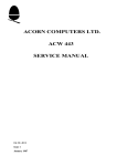
Service
c7lianual
nib.
ARP2435
ORDER
FM/AM DIGITAL SYNTHESIZER TUNER
F93
HEWZI
• Refer to the service manual ARP2221 for F-93.
• This manual is applicable to F-93/HEWZI.
CONTRAST OF MISCELLANEOUS PARTS
NOTES:
• Part without part number cannot be supplied.
• The mark found on some component parts indicates the importance of the safety factor of the part. Therefore, when replacing,
be sure to use parts of identical designation.
• Parts marked by "0" are not always kept in stock. Their deliver); time may be longer than usual or they may be unavailable.
F-93/HEWZI and F-93/HEVVZ have the same construction except for the following:
Mark
Symbol & Description
Part No.
F-93/HEWZ
---i
ARC1352
Operating instructions (Italian)
Rear panel
PIONEER ELECTRONIC CORPORATION
Remarks
F-93/HEWZI
Non supply
Non supply
4-1, Meguro 1-Chome, Meguro-ku, Tokyo 153, Japan
PIONEER ELECTRONICS SERVICE INC. P.O. Box 1760, Long Beach, California 90801 U.S.A.
PIONEER ELECTRONICS OF CANADA, INC. 505 Cochrane Drive, Markham, Ontario L3R 8E3 Canada
PIONEER ELECTRONIC [EUROPE] N.V. Haven 1087 Keetberglaan 1, 9120 Melsele, Belgium
PIONEER ELECTRONICS AUSTRALIA PTY. LTD. 178-184 Boundary Road, Braeside, Victoria 3195, Australia TEL: [03] 580-9911
C
PIONEER ELECTRONIC CORPORATION 1992
FO JAN. 1992 Printed in Japan
(ID PIONEER°
The Art of Entertainment
Service
c7Ilanual
ORDER NO.
ARP2 2 21
FM/AM DIGITAL SYNTHESIZER TUNER
F93
F-93 HAS THE FOLLOWING:
Remarks
Power Requirement
Type
KU/CA
AC 120 V only
HEWZ
AC 220-230 V, AC 230-240 V(switchable)*
HE
AC 220-230 V, AC 230-240 V(switchable)*
HB
AC 220-230 V, AC 230-240 V(svvitchable)*
SD
AC 110 V, 120 V-127 V, 220V, 240 V(switchable)
.
* Change the connection with the primary wire of the power transformer.
• This manual is applicable to the KU/CA, HEWZ, HE, HB and SD types.
• As to the HEWZ, HE, HB and SD types, refer to page 59.
• Ce manuel pour le service comprend les explications de reglage en francais.
• Este manual de servicio trata del metodo ajuste escrito en espaiiol.
CONTENTS
1. SAFETY INFORMATION
2
6. AJUSTE
51
2. EXPLODED VIEWS, PACKING AND PARTS LIST
3
7.1C INFORMATION
56
3, P.C.B's PARTS LIST
9
8. CIRCUIT DESCRIPTION
58
4. SCHEMATIC DIAGRAM
15
9. FOR HEWZ, HE, HB AND SD TYPES
59
5, P.C. BOARDS CONNECTION DIAGRAM
31
10. PANEL FACILITIES
62
6. ADJUSTMENTS
41
11. SPECIFICATIONS
66
6. REGLAGE
46
PIONEER ELECTRONIC CORPORATION
4-1, Meguro 1-Chome, Meguro-ku, Tokyo 153, Japan
PIONEER ELECTRONICS SERVICE INC. P.O. Box 1760, Long Beach, California 90801 U.S.A.
PIONEER ELECTRONICS OF CANADA, INC. 505 Cochrane Drive, Markham, Ontario L3R 8E3 Canada
PIONEER ELECTRONIC [EUROPE] N.V. Keetberglaan 1, 9120 Beveren, Belgium
PIONEER ELECTRONICS AUSTRALIA PTY. LTD. 178-184 Boundary Road, Braeside, Victoria 3195, Australia TEL: [03] 580-9911
0
PIONEER ELECTRONIC CORPORATION 1991
FO APR. 1991 Printed in Japan'
F-93
This service manual is intended for qualified service technicians; it is not
meant for the casual do-it-yourselfer. Qualified technicians have the necessary test equipment and tools, and have been trained to properly and safely
repair complex products such as those covered by this manual.
Improperly performed repairs can adversely affect the safety and reliability
of the product and may void the warranty. If you are not qualified to
perform the repair of this product properly and safely, you should not risk
trying to do so and refer the repair to a qualified service technician.
WARNING
Lead in solder used in this product is listed by the California Health and Welfare agency as
a known reproductive toxicant which may cause birth defects or other reproductive harm
(California Health & Safety Code, Section 25249.5).
When servicing or handling circuit boards and other components which contain lead in
solder, avoid unprotected skin contact with the solder. Also, when soldering do not inhale
any smoke or fumes produced.
1. SAFETY INFORMATION
—(FOR USA MODEL ONLY)
1. SAFETY PRECAUTIONS
The following check should be performed for the
continued protection of the customer and service
technician.
LEAKAGE CURRENT CHECK
Measure leakage current to a known earth ground
(water pipe, conduit, etc.) by connecting a leakage
current tester such as Simpson Model 229-2 or
equivalent between the earth ground and all exposed
metal parts of the appliance (input/output terminals,
screwheads, metal overlays, control shaft, etc.). Plug
the AC line cord of the appliance directly into a 120V
AC 60Hz outlet and turn the AC power switch on. Any
current measured must not exceed 0.5mA.
Reading should
not be above
0.5mA
Test all
exposed metal
surfaces
. . .n
. . Also test with
'-''''
reversed
Jplug
(Using AC adapter
plug as required/
AC Leakage Test
2
Earth
ground
ANY MEASUREMENTS NOT WITHIN THE LIMITS
OUTLINED ABOVE ARE INDICATIVE OF A POTENTIAL SHOCK HAZARD AND MUST BE CORRECTED BEFORE RETURNING THE APPLIANCE TO
THE CUSTOMER.
2. PRODUCT SAFETY NOTICE
Many electrical and mechanical parts in the appliance have special safety related characteristics. These
are often not evident from visual inspection nor the
protection afforded by them necessarily can be obtained by using replacement components rated for voltage, wattage, etc. Replacement parts which have
these special safety characteristics are identified in
this Service Manual.
Electrical components having such features are
identified by marking with a & on the schematics and
on the parts list in this Service Manual.
The use of a substitute replacement component which
dose not have the same safety characteristics as the
PIONEER recommended replacement one, shown in
the parts list in this Service Manual, may create shock,
fire, or other hazards.
Product Safety is continuously under review and
new instructions are issued from time to time. For
the latest information, always consult the current
PIONEER Service Manual. A subscription to, or additional copies of, PIONEER Service Manual may be
obtained at a nominal charge from PIONEER.
2. EXPLODED VIEWS, PACKING AND PARTS LIST
NOTES:
•
Parts without part number cannot be supplied.
•
Parts marked by "*" are not always kept in stock. Their delivery time may be longer than usual or they may be
unavailable.
•
The
mark found on some component parts indicates the importance of the safety factor of the part.
Therefore, when replacing, be sure to use parts of identical designation.
A
2.1 EXTERIOR SECTION
Parts List of Exterior
•■■•
Mark No. Description
1 ROTARY KNOB
2 NAME PLATE (METAL)
3 SCREW (STEEL)
4 SCREW (STEEL)
5 SCREW
1
6 SCREW (STEEL)
7 AC POWER CORD
8 SPACER
9 WOOD COLLAR
10 BARRIER
11 SPACER
12 SPACER SUPPORT
13 FOOT
14 INDICATING LENS
15 SIDE BOARD L
Parts No.
AAB1232
ABA1011
ABA1048
ABA1074
ABA1086
ADGI057
AEC1165
AEP-I82
AMR1159
AMR1160
AMS1054
16
IMMINO
16 SIDE BOARD R
17 CHASSIS
18 FRONT PANEL
19 REAR PANEL
20 PCB HOLDER
AMS1055
ANB1469
21 TRANS. HOLDER
22 HOLDER C
23 HOLDER D
AN 24 T701 POWER TRANSFORMER ATT1156
25 HOLDER
26 NUT
27 NUT
28 BONNET
29 C723 CKA (0.01/AC150V)
30 SCREW (STEEL)
NK7OFUC
NK9OFUC
PYY1093
AC01005
ABA1009
31 S801 ROTARY ENCODER
32 TUNER ASSEMBLY
33 IF ASSEMBLY
34 SCREW
35 SCREW
ASX1011
AWZ3501
AWZ3319
BBZ30P080FZK
ABA1047
36 WASHER
37 SCREW
WA92F1401/100
VMZ30P060FCU
18
PANEL BASE(AMB1821)
14
MOEN
13
2
3
0
tIZ BI 9 V1V)3SV9 131,1%
a
.1.1•••■
Iml•••■
CO
9
0
2
F — 93
3
2.2 FRONT PANEL SECTION AND PACKING
Parts List of Front Panel and Packing
Mark No. Description
1 KNOB (PLASTIC)
2 LIGHT ACTION BUTTON
3 KNOB
4 FL FILTER
5 PANEL(PVC)
6
17
Parts No.
AAD1016
AAD1733
AAD1971
AA101300
AAK2191
6 PANEL
7 PANEL BASE
8 HINGE L
9 RINGER
10 MAGNET PLATE
AAK2158
AMB1821
11 EJECT ASSEMBLY
12 SHAFT ASSEMBLY L
13 SHAFT ASSEMBLY R
14 DOOR PANEL
15 DISPLAY ASSEMBLY
AWL1081
AWL1082
AWL1083
ANB1468
AWZ33I8
16 SCREW
17 SCREW
18 SCREW (STEEL)
19 SCREW
20 MAGNET
PBZ20P040FZK
BPZ26PO8OF8SC
ABA1009
BPZ30P080FZK
AXX1016
21 DUMPER
22 PLUG CORD
23 CORD WITH PLUG (MINI)
24 FM ANTENNA
23 LITERATURE BAG
AXA1010
ADE-081
ADE-085
ADFI-005
26 RF TRANSFORMER
27 OPE. INSTRUCTIONS(E)
28 PAD
29 PACKING CASE
30 L BAR ANTENNA
AKX-080
ARB1328
AHA1434
AHD2063
ATB-086
31 PACKING SHEET
32 SPRING
33 SCREW
ARG1017
ABE11073
ABAI125
ANGI558
30
23
28
7
2
3
2
3
A
4
17
MIME
MIN
D.
"A,.B : Porto of PANEL BASE
7
1
2
3
5
6
F - 93
3. P.C.B.'s PARTS LIST
NOTES:
• Parts without part number cannot be supplied.
• Parts marked by "C)" are not always kept in stock. Their delivery time may be longer than usual or they may be
unavailable.
•
The
mark found on some component parts indicates the importance of the safety factor of the part.
Therefore, when replacing, be sure to use parts of identical designation.
• When ordering resistors, first convert resistance values into code form as shown in the following examples.
Ex. 1
When there are 2 effective digits (any digit apart from 0), such as 560 ohm and 4 7k ohm (tolerance is
shown by J = 5%, and K = 10%)
J
56012 56 x 10' 561
RD1/4PS
7- J
RD1/4PS
4 Mg 47X 10 3 473
0.50 OR5
RD2H OR 5K
117 010
RD1P o jxEx.2
When there are 3 effective digits (such as in high precision metal film reS;stors).
5.62kil 562 x 10' 5621
RD1/4SR15., 6
Mark No. Description
Parts No.
C)FM VCO ASSEMBLY (AWC1004)
Mark No. Description
Parts No.
OTUNER ASSEMBLY (AWZ3501)
SEMICONDUCTORS
SEMICONDUCTORS
Q8 TRANSISTOR
Q9 MOS-FET
2SC2668
2SK241
D3 VARI-CAP DIODE *1
KV1320-5
L17 COIL
L18 COIL
ATH-093
ATC-077
COIL
CAPACITORS
ICI, IC2
IC201-1C203 FM IC
10204,1C205 OP-AMP IC
IC301,1C302 FM-NR
IC303-IC310 OP-AMP IC
CXA1355L
PA5008
RC4558DXP
PA0042
RC4558DXP
1C311-1C314 OP-AMP IC
IC315 OP-AMP IC
IC401 PLL SYNTHESIZER IC
IC501 AM IC
IC502 LOGIC IC
UPC4570HA
RC4558DXP
CX-7925B
LA1247
UPD4066BC
IC601 MPX IC
IC701 REGULATOR IC
IC801 TUNER CONTROL p-COM
PA5007
NJM78M56FAS
PD5161A
C33 CERAMIC CAPACITOR
C34 CERAMIC CAPACITOR
C35 CERAMIC CAPACITOR
C36 CERAMIC CAPACITOR
C37 CERAMIC CAPACITOR
CKDYX103M25
CCDCH150J50
CCDCH330J50
CCDCH010C50
CCDTH080D50
C38 CERAMIC CAPACITOR
C39 CERAMIC CAPACITOR
C40 CERAMIC CAPACITOR
C42 CERAMIC CAPACITOR
CCDSH120J50
CCDSH330J50
CCDCH030C50
CKDYX103M25
Q1 TRANSISTOR
Q2 TRANSISTOR
Q3 TRANSISTOR
Q4 TRANSISTOR
Q5 FET
2SA1115
XDA124ES
2SC2705
2SC2603
3SK122
RD1/8PMDDEJ
Q6 N-FET
Q7 FET
Q10,Q11 TRANSISTOR
Q201-Q204 N-FET
Q205 TRANSISTOR
2SK16i
3SK122
XDO124ES
2SK246
XDC124ES
Q206 TRANSISTOR
Q207 N-FET
Q208 TRANSISTOR
Q209 P-FET
Q301 TRANSISTOR
2SC2878
2SK246
2SC2603
2SJ103
2SA1145
RESISTORS
All Resistors
*ENCODER ASSEMBLY (AWZ3321)
SWITCH
S801 ROTARY ENCODER
ASX1011
CAPACITOR
C811 CKA (0.01/25V)
ACG-036
*1 ; Specifications for 03-1 to 03-5 are matched. If you change 03-1 to D3-4, at the same time also change
FM VCO assembly. Likewise, if you change FM VCO assembly, at the same time change 03-1 to D3-4.
In the case of both of the above mentioned, D3-1 to D3-4 parts are mounted on the newly ordered
FM VCO assembly ; use spare parts.
9
1
0
Parts No.
Parts No.
Mark No. Description
Q302 TRANSISTOR
Q303 TRANSISTOR
Q304 TRANSISTOR
Q401 N-FET
Q402 TRANSISTOR
XDC143ES
2SA1145
XDC143ES
2SK246
2SA1115
RELAYS
Q403 TRANSISTOR
Q501 N-FET
Q502 TRANSISTOR
Q503 TRANSISTOR
Q504 TRANSISTOR
2SC2603
2SK246
2SA1115
2502603
XDA124ES
COILS, FILTERS AND TRANSFORMERS
Q505,Q506 N-FET
Q507 TRANSISTOR
Q601-Q603 N-FET
Q701 N-FET
Q702 TRANSISTOR
2SK246
2SC2603
2SK117
2SK246
2SB834
Q703,Q704 TRANSISTOR
Q705 TRANSISTOR
Q706 TRANSISTOR
Q707 TRANSISTOR
Q708 TRANSISTOR
2SC2603
XDC143ES
2SA1529
2SA1115
2SB834
Q709-Q712 TRANSISTOR
Q713 TRANSISTOR
Q714 TRANSISTOR
Q715,Q716 TRANSISTOR
Q717,Q718 TRANSISTOR
2SC2878
XDA143ES
XDC124ES
2SC2603
XDC124ES
Q719 TRANSISTOR
Q801 TRANSISTOR
Q802,Q804 TRANSISTOR
Mark No. Description
RY1 RELAY
RY301 RELAY
RY302 RELAY
ASR-087
ASR1018
ASR1018
Li-LID AXIAL INDUCTOR
L11 COIL
L12 AXIAL INDUCTOR
L14 AXIAL INDUCTOR
L15,L19,L20 AXIAL INDUCTOR
LAU010M
ATC-244
LAU010M
LAU2R2M
LAUOIOM
L21 AXIAL INDUCTOR
L22 AXIAL INDUCTOR
L23 AXIAL INDUCTOR
L24 AXIAL INDUCTOR
L25-L27 AXIAL INDUCTOR
LAUR56M
LAUR39K
LAUR56M
LAUR39K
LAU010M
L201,L202 AXIAL INDUCTOR
L204 COIL
L205 AXIAL INDUCTOR
L206-L210 AXIAL INDUCTOR
L211 AXIAL INDUCTOR
LAU2R2M
ATM1004
LAU2R2M
LAU221K
LAU220K
L401 AXIAL INDUCTOR
L501 IF TRANSFORMER
L502 AXIAL INDUCTOR
L601 COIL
L801 AXIAL INDUCTOR
LAU2R2M
ATB-073
LAU470K
ATM1003
LAU220K
2SC2603
XDC124ES
2SC2603
F501 CERAMIC FILTER
F502 CERAMIC FILTER
ATF1004
ATF1077
D1,D4 DIODE
D2 DIODE
D201,D202 ZENER DIODE
D203 ZENER DIODE
D204 VARI-CAP DIODE
1SV156
1SS252
RD8.2FB
RD4.7ESB
SVC321SP
T2 RF TRANSFORMER
T3 COIL
T4 RF TRANSFORMER
T5 RF TRANSFORMER
T7 IF TRANSFORMER
ATG-257
ATG-204
ATC-257
ATC-218
ATE1011
D205-D207 DIODE
D301,D302 ZENER DIODE
D303-D307,D401-D404 DIODE
D405 ZENER DIODE
D501,D502 VARI-CAP DIODE
1SS252
RD8.2FB
1SS252
RD7.5EB
SVC321C2
T201,T202 IF TRANSFORMEF.
T203 IF TRANSFORMER
T501 COIL
T502 IF TRANSFORMER
ATE-068
ATE1010
ATB-08 7
ATB1002
D503 DIODE
D504 ZENER DIODE
D505 DIODE
D601 ZENER DIODE
D701-D706 DIODE
1SS252
RD5.1ESB
1 SS252
RD8.2FB
10DF2FD
D707-D710 DIODE
D711,D712 ZENER DIODE
D713,D7I4 ZENER DIODE
D715 ZENER DIODE
D716 DIODE
S5566
RD12ESB
HZS9A3L
HZS6C2L
155252
D717 ZENER DIODE
D719 ZENER DIODE
D720 ZENER DIODE
D721 DIODE
D722-D725 DIODE
HZS9A3L
RD8.2ESB
RD2.2ESB
1SS252
10DF2FD
D801,D802,D804-D809 DIODE
1SS252
CAPACITORS
Cl-05 CKA (0.01/25V)
C6 CERAMIC CAPACITOR
C7 CERAMIC CAPACITOR
C8,C9 CERAMIC CAPACITOR
C10 CERAMIC CAPACITOR
ACC-036
CCDCH220J50
CCDCH100D50
CCDSH100D50
CCDCH030C50
C11,C12 CERAMIC CAPACITOR
013 CERAMIC CAPACITOR
C14 CERAMIC CAPACITOR
C15,C18 CERAMIC CAPACITOR
C18,C19 CERAMIC CAPACITOR
CCDSH030C50
CCDSHIOOD50
CCDCH030050
CCDSH030050
CCDSH100D50
C20,C21 CERAMIC CAPACITOR
023-026 CERAMIC CAPACITOR
C27,C28 CERAMIC CAPACITOR
C29,C30 CKA (0.01/25V)
043,044 CERAMIC CAPACITOR
CCDC11150J50
CCDCH220J50
CCDSL221J50
ACG-036
CCDCH100D50
Mark No. Description
Parts No.
Mark No, Description
Parts No.
045 CERAMIC CAPACITOR
CCDCH150J50
C46,C47,C50 CKA (0.01/25V)
ACG-036
055,059 CKA (0.047/25V)
ACG-037
C60,C62,C63,C65,C66, CKA (0.01/25V) ACG-036
C69,C72,C73
0302 CKA (0.047/25V)
0303 ELECTROLYTIC CAPACIT
0304 CKA (0.047/25V)
C306 ELECTROLYTIC CAPACIT
0307 CKA (0.047/25V)
ACG-038
CEEA222M16
ACG-038
CEEA222M16
A CG-038
074 CERAMIC CAPACITOR
C75-C78 CKA (0.01/25V)
080,081 CERAMIC CAPACITOR
C82 CERAMIC CAPACITOR
083-C85 CKA (0.047/25V)
CCDSHIOOD50
ACC-036
CKDYX4731925
CKDYX103M25
ACG-037
CEEA100M25
C308,C309, ELECTR. CAPACIT
0312,0313,0314,C315
0316 ELECTROLYTIC CAPACIT
CEEANP100M25
C317,C318 ELECTROLYTIC CAPACIT CEAS6R8M50
CEAS4R7M50
C319-C321 ELECTR.CAPACITOR
C86,C87 CKA (0.01/25V)
C88 ELECTR.CAPACITOR
C89-C98 CKA (0.01/25V)
099 CERAMIC CAPACITOR
0201,0202 CKA (0.01/25V)
ACG-036
CEAS101M16
ACG-036
CKDYX103M25
ACG-036
0322 ELECTROLYTIC CAPACIT
0323,0324 ELECTR. CAPACITOR
0325 ELECTROLYTIC CAPACIT
C326-C330 ELECTR.CAPACITOR
0331-0333 ELECTR.CAPACITOR
CEAS1R5M50
CEAS010M50
CEEANP100M25
CEAS010M50
CEASOR1M50
C203,C204 CKA (0.047/25V)
0205 CKA (0.047/25V)
0206 ELECTROLYTIC CAPACIT
0207 CKA (0,047/25V)
0209 ELECTROLYTIC CAPACIT
ACG-037
ACG-038
CEEA1021■ 116
ACG-038
CEEA220M25
0334 POLYESTER CAPACITOR
C335 POLYESTER CAPACITOR
C336 POLYESTER CAPACITOR
0337 POLYESTER CAPACITOR
0338 POLYESTER CAPACITOR
CQMXA823J100
CQMXA2233100
CQMXA6833100
CQMXA1533100
CQMXA5633100
C210 ELECTROLYTIC CAPACIT
0211,0212 CKA (0.047/25V)
0213 ELECTROLYTIC CAPACIT
0214 CKA (0.047/25V)
0215 CKA (0.047/25V)
CEEA222/416
ACG-037
CEEA102M16
ACG-037
ACG-038
C339 POLYESTER CAPACITOR
C340 POLYESTER CAPACITOR
C341 POLYESTER CAPACITOR
0392 POLYESTER CAPACITOR
0343 POLYESTER CAPACITOR
CQMXA123,1100
CQMXA393J100
CQMXA103J100
CQMXA3333100
CQMXA6823100
0217 ELECTROLYTIC CAPACIT
C219 CKA (0.047/25V)
0220 ELECTROLYTIC CAPACIT
0222 PL.STYRENE CAPACITOR
0223 CKA (0.01/25V)
CEEA222M16
ACG-037
CEEA220M25
CQSA821350
ACG-036
0344 POLYESTER CAPACITOR
0395 POLYESTER CAPACITOR
0346 POLYESTER CAPACITOR
0347 POLYESTER CAPACITOR
0348 POLYESTER CAPACITOR
CQMXA2233100
CQMXA5623100
CQMXA183J100
CQMXA392J100
CQMXA123J100
0224,0225 CKA (0.047/25V)
0226 ELECTRCAPACITOR
C227 CKA (0.047/251
C231 CKA (0.047/25V
0232 ELECTR.CAPACITOR
ACG-037
CEAS101M16
ACG-038
ACG-037
CEAS471M10
C399 POLYESTER CAPACITOR
0350 POLYESTER CAPACITOR
0351 POLYESTER CAPACITOR
0352 POLYESTER CAPACITOR
0353 POLYESTER CAPACITOR
CQMXA3323100
CQMXA1033100
CQMXA272.1100
CQMXA8223100
CQMXA182J100
C234 CERAMIC CAPACITOR
0235 ELECTR.CAPACITOR
C236,C237 ELECTROLYTIC CAPACIT
0240 ELECTR.CAPACITOR
0241 PL.STYRENE CAPACITOR
CCDCH220350
CEAS010M50
CEANP100M25
CEAS010M50
CQSA471350
C354 POLYESTER CAPACITOR
C355 POLYESTER CAPACITOR
C356 POLYESTER CAPACITOR
0357 POLYESTER CAPACITOR
0358 POLYESTER CAPACITOR
CQMXA6823100
CQMXA1523100
CQMXA4723100
CQMXA1223100
CQMXA3923100
0242 ELECTR.CAPACITOR
0243 CERAMIC CAPACITOR
0244,0246 ELECTR.CAPACITOR
0247,0248 CERAMIC CAPACITOR
0249 CKA (0.01/25V)
CEAS2R2M50
CKDYX223M25
CEAS4R7M50
CCDSL181J50
ACG-036
C359 PL.STYRENE CAPACITOR
0360 POLYESTER CAPACITOR
C361 PL.STYRENE CAPACITOR
0362 POLYESTER CAPACITOR
0363 PL.STYRENE CAPACITOR
CQSA821J50
CQMXA2723100
CQSA681J50
CQMX A 2223100
CQSA561J50
0250 ELECTR.CAPACITOR
C251 CKA (0.047/25V)
C252 ELECTR.CAPACITOR
0254 CKA (0.047/25V)
C255 ELECTR.CAPACITOR
CEAS470M16
ACG-037
CEAS010M50
ACG-037
CEAS010M50
0364 POLYESTER CAPACITOR
C365 PL.STYRENE CAPACITOR
C366-C373 PL.STYRENE CAPACITOR
0374 ,C375 POLYESTER CAPACITOR
C376-C380,C383 CKA (0.047/25V)
CQAIXA1823100
CQSA391J50
CQSA103J50
CQMXA1033100
ACG-037
0256 ELECTR.CAPACITOR
0257,0258 CERAMIC CAPACITOR
0259-0264 CKA (0.047/25V)
C265 CERAMIC CAPACITOR
0301 ELECTROLYTIC CAPACIT
CEAS470M16
CCDSL181350
ACG-037
CCDCH680J50
CEEA1023d16
0401 CKA (0.01/25V)
0402 CERAMIC CAPACITOR
0403 CERAMIC CAPACITOR
C404 CKA 0.01/25V)
0405 CKA 0.047/2W)
ACC-036
CCDC1-1150.150
CCDC11220350
ACG-036
ACG-037
11
Mark No. Description
Parts No.
Parts No.
Mark No. Description
0406 ELECTR.CAPACITOR
0407 ELECTR.CAPACITOR
C408 ELECTROLYTIC CAPACIT
C409 POLYESTER CAPACITOR
C410 ELECTR.CAPACITOR
CEAS1015110
CEAS470M25
CEANLR47M50
CQIIXA103J100
CEAS1015135
C636,C637 CERAMIC CAPACITOR
0702 ELECTROLYTIC CAPACIT
C703 ELECTROLYTIC CAPACIT
0704 ELECTR.CAPACITOR
0705 ELECTR. CAPACITOR
CCDSLIO1J50
CEAS4705135
CEAS221M63
CEAS2215150
CEAS471M50
0411 ELECTROLYTIC CAPACIT
C412 CKA (0.047/25V)
0501 CERAMIC CAPACITOR
0502 PL.STYRENE CAPACITOR
C503 CERAMIC CAPACITOR
CEEA2R2M50
ACG-037
CCDUJ100D50
CQSA471J50
CKDYX223M25
0706 ELECTROLYTIC CAPACIT
C707 CKA (0.047/25V)
C708 ELECTROLYTIC CAPACIT
C709 ELECTROLYTIC CAPACIT
0711,0712 ELECTROLYTIC CAPACIT
CEEA332M35
ACG-038
CEHAQ101M16
CEHAQ101M25
CEEA1015425
C504 CKA (0.01/25V)
0505 CERAMIC CAPACITOR
0506 CERAMIC CAPACITOR(0.01p)
C507 CERAMIC CAPACITOR(0.022y)
0508 ELECTR.CAPACITOR
ACG-036
CCDSL101J50
ACG1021
ACG1022
CEAS1005150
0713 ELECTR.CAPACITOR
0715 ELECTR.CAPACITOR
0716 ELECTROLYTIC CAPACIT
0717 ELECTR.CAPACITOR
0718 ELECTR. CAPACITOR
CEAS2225125
CEASIO1M16
CEAS471 M25
CEAS470M25
CEAS101M16
0509 CKA (0.01/25V)
0510 CERAMIC CAPACITOR
C511 CERAMIC CAPACITOR(1000p)
0512 CERAMIC CAPACITOR(0.022y)
0513 CERAMIC CAPACITOR(001j)
ACC-036
CKDYX223M25
ACG1020
ACG1022
ACG1021
C720 ELECTR.CAPACITOR
C721 ELECTR.CAPACITOR
C722 CERAMIC CAPACITOR
C801 CERAMIC CAPACITOR
0802 ELECTR. CAPACITOR
CEAS220M25
CEAS100M50
CKDYX2235125
CCDSL101J50
CEAS100M25
0514 ELECTR.CAPACITOR
0515 CERAMIC CAPACITOR(0.01y)
0516 CERAMIC CAPACITOR
05I7 CERAMIC CAPACITOR(1000p)
0518,0519 ELECTR.CAPACITOR
CEAS330M16
ACG1021
CKDYX223M25
ACG1020
CEAS4R75150
C803 CERAMIC CAPACITOR
0804 CEA (47000/5.5V)
0805 CERAMIC CAPACITOR
0806 ELECTR.CAPACITOR
C807,C808 CKA (0.01/25V)
CCDSL101J50
ACH1037
CKDYX223M25
CEAS4705116
ACG-036
0520 MYLOR FILM CAPACITOR
0521 MYLOR FILM CAPACITOR
0522 ELECTR.CAPACITOR
0523 CERAMIC CAPACITOR(0.0228L)
C524 CERAMIC CAPACITOR
CQMA393J50
CQMA103J50
CEAS330M16
ACG1022
CKDYX223M25
0809 CERAMIC CAPACITOR
0810 CERAMIC CAPACITOR
CKDYX223M25
CCDSL101J50
TC1-TC4 CERAMIC TRIMMER
TC501,TC502 CERAMIC TRIMMER
ACM-018
ACM-019
0525,0526 ELECTR. CAPACITOR
0527 ELECTR.CAPACITOR
C528 ELECTR.CAPACITOR
0529 CERAMIC CAPACITOR(0.0220)
0530 CKA (0.01/25V)
CEAS010M50
CEAS3305116
CEASOR15150
ACG1022
ACG-036
C601,C602 PL.STYRENE CAPACITOR
C603 ELECTR. CA PACITOR
0604 CKA (0.047/25V)
C605 ELECTROLYTIC CAPACIT
0606 ELECTROLYTIC CAPACIT
CQSXA222J160
CEAS470M25
ACG-038
CEEA222M25
CEEA102M16
0608 ELECTR.CAPACITOR
0609 ELECTROLYTIC CAPACIT
0610 CKA (390P/50V)
0611 ELECTROLYTIC CAPACIT
C612, C613 ELECTR.CAPACITOR
CEAS100M25
CEAS1R5M50
ACG-023
CEAS6R8M50
CEAS100M25
C614 PL.PROPYTENE CAPACIT
0615 ELECTR.CAPACITOR
0616,0617 ELECTROLYTIC CAPACIT
C618,C619 POLYESTER CAPACITOR
0621,0622 CERAMIC CAPACITOR
CQPA682G100
CEAS330M16
CEEA1005125
CQMXA822J100
CCDC11330.150
C623 ELECTR.CAPACITOR
C625,C626 POLYESTER CAPACITOR
C629,C630 ELECTROLYTIC CAPACIT
C631 CKA (0.047/25V)
C634,C635 ELECTROLYTIC CAPACIT
CEAS0105150
CQMXA822J100
CEEA1005125
ACG-038
CEEA100M25
RESISTORS
VR201,VR202 VR(2200)
VR203 VR(1K)
VR204,VR205 VEri
VR206,VR207 VR 10K
VR208 VR(1K)
1
ACP1038
ACP1040
ACP1044
ACP1043
ACP1040
VR209-VR211 VR
VR301,VR302 VR 47K
10
VR303, VR304 VR 9.7K)
VR501 VR(47K)
VR601 VR
ACP1043
ACP1045
ACP1042
ACP1045
VRTS6VS222
VR602 VT2K)
VR603 VR 2K)
VR604 SEMI-FIXED RESISTOR
VR605-VR607 VR(10K)
ACP1044
ACS1069
VRTB6VS103
ACP1043
R8 CARBON FILM RESISTOR
R16 RESISTOR
R40,R41 CARBONFILM RESISTOR
R202 CARBON FILM RESISTOR
R206,R207 CARBON FILM RESISTOR
RD1/4P51151J
RFA1/4PS100J
RD1/2P11103J
RDR1/4P51102J
RDR1/4PM102J
R210 CARBON FILM RESISTOR
R213,R214 CARBON FILM RESISTOR
R218 CARBON FILM RESISTOR
R219 CARBON FILM RESISTOR
R301-R306 CARBON FILM RESISTOR
RDR1/4P511023
RDR1/4PM102J
RDR I /6PIJ392J
RDR1/4P51103J
RDR1/4PMMEJ
12
Parts No.
Mark No. Description
R339-R362 CARBON FILM RESISTOR
R363 CARBON FILM RESISTOR
R366-R369 CARBON FILM RESISTOR
1370,R371 CARBON FILM RESISTOR
R374 CARBON FILM RESISTOR
RDRI/4PMECID
RD1/4PM221J
RDR1/6PUDEIDJ
RDR1/4PM362J
RD1/4PM221J
CAPACITORS
R418-R420 CARBON FILM RESISTOR
R510 CARBON FILM RESISTOR
R517 CARBON FILM RESISTOR
R601-R604 CARBON FILM RESISTOR
R607-R612 CARBON FILM RESISTOR
RDR1/4PM105J
RD1/4PM151J
RDR1/4PM1023
RDR1/4PM223J
RDR1/4PMI I I b
OTHERS
R614 METALFILM RESISTER
R616-R623 CARBON FILM RESISTOR
11625 CARBON FILM RESISTOR
11628 CARBON FILM RESISTOR
R634-R637 CARBON FILM RESISTOR
RN1/4PQ5601F
RDR1/4PM I=E
RDR1/4PM222J
RDR1/4PM222J
RDIU/4PMELED
*IF ASSEMBLY (AWZ3319)
R701,R702 CARBONFILM RESISTOR
11703 CARBON FILM RESISTOR
11709 CARBON FILM RESISTOR
11710 METAL OXIDE RESISTOR
11712 CARBONFILM RESISTOR
RD1/2PM47IJ
RD1/4PM6811
RD1/4PM222.1
RS2LMF2R2J
RDI/2PM101J
11713-R716 CARBON FILM RESISTOR
R732 RESISTOR(2.2M, 1/2W)
R733-R735 METAL OXIDE RESISTOR
11812 CARBON FILM RESISTOR
R820 RESISTOR ARRAY(22K)
RD1/4PM010J
ACN-208
RS3LMF120J
RD1/4PM101J
RA8T223J
R825 RESISTOR ARRAY(22K)
RA8T223J
!Mark No. Description
Other Resistors
RD1/8PMDCEJ
C901, C902 CERAMIC CAPAU r(0.022p) ACG1022
RESISTORS
R902,R903 CARBON FILM RESISTOR RD1/4PM151J
Other Resistors
V901 FL TUBE
RD1/8PMODDJ
AAV1121
SEMICONDUCTORS
IC101-IC109 AMPLIFIER IC
IC110 FM IC
1C931-1C939 OP-AMP IC
TA7060AP
PA5008
RC4558DXP
Q101,Q102 TRANSISTOR
Q103,Q104 TRANSISTOR
Q105 TRANSISTOR
Q106,Q107 TRANSISTOR
Q108-Q110 MOS-FET
XDA143ES
2SC2668
XDC124ES
2SC2603
2SK241
Q111-Q114 TRANSISTOR
Q115 TRANSISTOR
2SC2668
2SC2603
D101-D112 DIODE
D113,D114 DIODE
D160,D161 DIODE
1SS85
2-1K261
ISV156
COILS, FILTERS AND TRANSFORM ERS
OTHERS
CN1 CONNECTOR 12P)
CN2 CONNECTOR 13P)
CN3 CONNECTOR 9P
CN4 CONNECTOR 4P
0N5 CONNECTOR 4P
KPE12
KPE13
KPE4
KPE4
KPE4
J PLUG CORD
ADE1111
X401 CRYSTAL RESONATOR
X501 CERAMIC RESONATOR
X502 CERAMIC RESONATOR
X801 CERAMIC RESONATOR
ASS1005
ATF1027
ATF1027
ASS1055
SCREW (STEEL)
PIN JACK(2P)
TERMINAL 2-P
JACK
SCREW
Parts No.
ABA1009
AKB1099
AKE-060
AKN1006
BBZ30P080FCU
*DISPLAY ASSEMBLY (AWZ3318)
SEMICONDUCTORS
L101,L102 AXIAL INDUCTOR
L103,L105,L106 AXIAL INDUCTOR
L160,L161 AXIAL INDUCTOR
L162 AXIAL INDUCTOR
LAU2R2M
LAU221K
LAUlOOK
LAU2R2M
F101-F108 CERAMIC FILTER
F109 CERAMIC FILTER
F110-F112 CERAMIC FILTER
FI13,F114 CERAMIC FILTER
ATF1080
ATF1079
ATF-119
ATF1079
T101-T106 IF TRANSFORMER
ATE-063
CAPACITORS
C101 CKA (0.01/25V)
C102,C103 CKA (1.047/25V)
C104,C105 CKA 0.01/25V)
C106 CKA 0.047/25V)
C107 CKA 0.01/25V)
ACG-036
ACG-037
ACG-036
ACG-037
ACG-036
C108-C110 CKA (0.047/25V)
C111,C112 CKA (0.01/25V)
C113 CKA $0.047/25V)
C114 CKA 0.01/25V)
C115-C117 CKA (0.047/25V)
ACG-037
ACG-036
ACG-037
ACG-036
ACG-037
C11$ CERAMIC CAPACITOR
C119 CKA (0.01/25V)
C120-C131 CKA 0.047/251/
C133-C138 CKA 0.047/25V
C160,C161 CERAMIC CAPACITOR
CCDCH101J50
ACG-036
ACG-037
ACG-037
CKDYX473M25
1C901-1C903 FL STATIC DRIVER IC LC7570
D901-D904 DIODE
D905 LED(RED,AMBER)
1SS252
AEL1115
SWITCHES
S901-S929 SWITCH
ASG1029
13
F - 93
Parts No.
Mark No. Description
0162 CERAMIC CAPACITOR
C163,0164 CERAMIC CAPACITOR
0165 CERAMIC CAPACITOR
C166,C167 CERAMIC CAPACITOR
C168 ELECTR.CAPACITOR
CKDYX103M25
CKDYX473M25
CKDYX103M25
CKDYX473M25
CEAS470M10
OTHERS
0169-0172 CERAMIC CAPACITOR
C173 ELECTR.CAPACITOR
C179 CERAMIC CAPACITOR
C175 CKA (0.047/25V)
0176-0178 CERAMIC CAPACITOR
CKDYX473M25
CEAS101M16
CKDYX473M25
ACG-037
CKDYX103M25
Mark No. Description
CN6 CONNECTOR(3P)
TH101 THERMISTOR
TH102 THERMISTOR
PIN JACK(1P)
Parts No.
KPE3
TH102-2
TH102-2
AKB1062
C931,C932 MYLOR FILM CAPACITOR CQMA103.150
0933 ELECTR.CAPACITOR CEAS470M16
C934,C935 MYLOR FILM CAPACITOR CQMA103J50
C936 ELECTR.CAPACITOR CEAS470M16
C937,C938 MYLOR FILM CAPACITOR CQMA103J50
CEAS470M16
0939 ELECTR,CAPACITOR
0940,C941 MYLOR FILM CAPACITOR CQMA103350
C942 ELECTR.CAPACITOR CEAS470M16
0943,0999 MYLOR FILM CAPACITOR CQMA103.150
C945 ELECTR.CAPACITOR CEAS470M16
0946,0947 MYLOR FILM CAPACITOR CQMA103J50
CEAS470M16
0998,0949 ELECTR,CAPACITOR
CQSA182J50
0950 PL.STYRENE CAPACITOR
C951,C952 PL.STYRENE CAPACITOR CQSA821,150
CQSA162J50
0953 PL.STYRENE CAPACITOR
0954 ELECTR.CAPACITOR
C955 ELECTR,CAPACITOR
0956 ELECTR.CAPACITOR
C958 ELECTR.CAPACITOR
C960 PL.STYRENE CAPACITOR
CEAS470M16
CEAS010M50
CEASIO1M16
CEAS470M16
CQSA182J50
C961,C962 PL.STYRENE CAPACITOR CQSA821J50
CQSA162.150
0963 PL.STYRENE CAPACITOR
CEAS470M16
0964 ELECTR.CAPACITOR
CEAS010M50
0965 ELECTR.CAPACITOR
CEASIO1M16
0966 ELECTR.CAPACITOR
0967 MYLOR FILM CAPACITOR
0968 MYLOR FILM CAPACITOR
0969 CKA (0.01/25V)
CQMA102350
CQMA223J50
ACG-036
RESISTORS
VR101 110K)
VR102 VR 2.2K)
VR932 VR 22K)
ACP1043
ACP1041
ACP1044
R109 CARBON FILM RESISTOR
R118 CARBON FILM RESISTOR
R127 CARBON FILM RESISTOR
R130 CARBON FILM RESISTOR
R133 CARBON FILM RESISTOR
RD1/9PM151J
RD1/4PM151J
RD1/9PM151J
RD1/4PM151J
RD1/4PM151J
R136 CARBON FILM RESISTOR
R139 CARBON FILM RESISTOR
R163 CARBON FILM RESISTOR
R168 CARBON FILM RESISTOR
RD1/4PM151J
RD1/4PM151J
RD1/4PM151J
RD1/4PM151J
Other Resistors
RD1/8PMEMJ
14
2
F - 93
4
3
4. SCHEMATIC DIAGRAM
r
L'
NEW-E.-1.1E- • • .5v233/71,
;8
'
TUNER ASSEMBLY(1/2)(AW23501,KU/CA TYPE)
A
6
7
R>23-R735
: [U2OA .......
• 1213110
LOENERS• • 2.852R15aoer. ..
.....
igen
0
%,0010.2.,..0502,07Q7
cia EW11./0
33
00 RE A*T1
2 2
j.;■ 4, VA
5
_
: 25,05
x0A128Es
2502705
:2502603
r
5 .02,08.0402.0502.
7 .07%. ""
07°1 6
2.: 7
60: .
C5,0 7
p6
p:p
I 38E122
0206 , 0709 -0712
Q209
1
„o5
17712.071,0801
0201-0204 .5207 .11.071
0501 .0505. 0506.0701
2.5e2a6
25N2 46
° 7°
Q
072
2502875
2.103
2.510334
250,152.
:25663a
■ 50 OHLy ■
A.13
ee
L
5=TEYEJ
.
,711-4:70.0;
••• J_* V AHU5
;;•!
IC: :MIXER
- 9
7,,71J
RFL' f*72 a?.
ICa 0, ELL
Oa;
LOCAL 05C
r-
na
glfiS”
2 2
03:
ZU%
2-
4--
'313
P13
!SI"
131
11 ta
7
emeal., Tel).
rommiiiiiiermuffiraf
re
1-13 a-t
113
Me 7
_LIVERTER
Ike!
•1510011
.11
ed.
0„A„: 50
06: BUFFER AN
leuz,
itr
P--'
ESS
13 1E1 IV NI 131 = MD
1192
ola
n WE To
a
(1:12
01.0.1
15v156
02.0206-0202.
155252
2401-0404.0503.0505.07 6.
0721 .0601 .11602 .06251-0509
0201,202
I ROB 2E8
D203
: RDe 7E58
0.4
, SvC3215P
0405
: RD7 5E8
0800:BUFFER
.
0501, 0502
SVC32122
070! -0806,07.22- 0725 : 1007270
0707-0710
: 55566
0711 11012E58
0713, 0, 701, 071 7
:11250A3L
D715
: /125602L
0716
: ROB 2E98
0720
' R02.2E58
orz
:
47,L:A°47'
111131
1.
lef j f.)
to OVIN 11111112l
i
1111111411
m`e'71
cZ2
I
C.
IMO • I
"
"
Vu'r'F'N
11,10,12.1.13.019,20. LA.11010,51
125,27
1..11
: AEC- 244
L . ,5201,L202,L203.0•101 IL Al2.251
2209
A781008
L206 - L.210
LAQ2215
L21,L23
EAUE568
1.722,L.
LA12173.5
L2/1,/.1301
1LAu22011
L50/
:4713 - 073
47502
1 1,04708
ema
■
;:.
f;I:AgS1
7•1' 4P
Y".
IC1,102
IC201-10205
:c
c 2.00e,iC205
1C301
IC302
10701
2501
2501
7:V2R7Z10
CAA 1336L
..5006
:RC:433010XE
c2-711255
:1,124 7
520•10661X
:57.758:56FeS
P0516.
1004
ATE 1017
8701. 864
T..... "
UM
0713,7,6: AC 2 1•11TER
411,0 j "ur-iEr
111
& MI I El
El 31 TE
earolinf
cm ---11 ionr
sal
il .
Mai
41
437' 77
CO
071,
POWER 51QTE
ma lato us to In nt au ul
07011- 07121 AL POwER 5817C11
AIM
"AA?
e-1/.25
'Ar
C502:
V'eTrEcl+
Mr EPLATOR
-
latmj
17:
11111131
tit
6,
*1 2020211 511 .2
NET
15
1
2
4
5
6
Z1
L
01
raiisr;::e-Rig7nWax'
;la•
as?,.,,' !case
1
Bialia
2.9:0
r casn• • •Eti•aw z•31,1 ,rnaao.• •81.31,2019101
• vers • ramo r ,mrsn
,
L tvneo..,
5?,?
as,,,vrue,
sz06
. ,
21
- 20.903 indw
.393:
YT
13239 000
i
Li
r
Cie
..,
-
t0:
EEL
„...
s snows
0321.5
.0. , „ ,.
•
7.-9.11,. OEM
.„."="armimmomme
0..
MNIII=1013
7.3,
1.20
20.210 :
2021
LBO 1.1
:00.
90.450 :
:00s
0:013111;
0021
.2. - 602.
12.311. 209S • 1009
3111; 2021,0.
0.3.104
302nn • 902an
200.50
10.
.013,4 :
21
tin
.01.39 .
000.. 002. ; 202. .0 -ss. :2003.111.3.1. 102 - 31p :
21
900.30 202...203
11 •
131- 132 <0.2 - 310
....
010.39:
NMI
an
. osalls
me sans•
.
6
....
.
....
„
,7g
...............
,.
...
I Os 210
01 J10 ;
"".
1111
Low:
i_otire
■9 ■ 20.1
920 3 99V: 1. '2
1 ■ 01020: :093
5139.02.31:
.99010. :
4121.:
;
.00320. •
9002.
1232,42
20
106
100
233
102
109
92230102
20231- .2
221 • ■
213
ssTs
seas
01%
:41
m
m.
•
11111114
Vs°
str ,s
11
NM' cm saiIu1
123.3
:2020
02 10,
A31
rstw,
. 1111
00133130 30231
`471
72::,‘,70
m1%
TV>
1
it'sol
•
,
319
1romi
%am
%wog•
I
sa
'sr,rosr,7-0-T
•223
.03
1.3,102
6222,29.2123 31103
sts,..ga'soso,
(0.4J • LL20,20,023,02,
2.3.3.9 • 1923-2220 . 102.1023• .29•02.11,222
Lt0. 131:.123 ; .23 . 2.22 .23,022 . 0023,03 - .2 ; 222 . 992
9022 , 092 • 0022 • 6032.092 . 1.3 . 1.2 . .z3 . aza . zon
• ■ 020.63-623 . 42. 923 . 92.332, 3 . 2.3030•393
940-991
.92 . 293. 222.23.32.2 39.3
. 622 . 23- 13
sY,
;131.
rNs
roo",
923. 209 ;
0032 900 •
1239220 ;
4 ,0 L n
1.252. ;
21532:22
92305
0/22001 : 02/0 - 2210. 9,
23.33.;
WHO 30 . 2,11. ■
20.33:3:
22.2123
02019. •
220.30
1201904
evo -900 :
CLIMM
3 MHZ1
grigill
AIX
.3
.2233.2 not2001.0 .2023;
all.
do
83.01: :2i
- 5 ' 1■I'Onc*:-5,, AtiON
.030• 202 0 .23
.133130 .02 a:
FAss
"--
Lowdalli
11
01
6
L
I
A
1
o
-
0101,0105.0,06 z IF BAWD SW,TC1.1
0102: AMP
0109 z peR
IC102
AA,
COO: aMP
0. , 2 z BUFFER
0113 :BUFFER
01 , •
rm.
opal
0102,0., IF 8.10 SwITC.
IC106,1[1091, AMP FOR METER
1C105 - rrlOr :
0103 :SUFFER
ME FL. 010, BUFFER
Est
6,1
AMP
M
1111110.31
0
•911119111Mill
iti ID g DETECTOR FOR METER
win
II
1111
gra NM. 1F*WrllIlMlmw
[.50
7.
1.71C /2 ,
'20'■
f444
Igrgto
ma.
mel
■ celon
- PC,09
■ C110
1.PPI
ICS3,10959
sol•.v
7,t
W
ig
Elw
"1/4
.111.i
NOi1143ES
.01.1,02
0103.0104 ,0,11- 0114 z ZSC2666
x0c12AES
C105
0106 , 0107, 0115
: 2302605
0106 -0110
:261(20/
'AL
amp
NIPMNIirad
.c,•,1
7' 3T--=
TA7000AP
IPA50061
RC453210XP
:141
0101 -D112
0113
0160,0161
IS665
12 -11(261
15056
F101- FIDS
F109,F113,114
FM- F112
:4,1000
LID1,02,162
L103,05,106
LIOC,L161
LAL2R2M
:1,02211,
AulOOF
ATF10,9
ATF -119
71.1iO ■ , X402
VRIO1
v
11.03;
C101.C104,C105.
r-11 , 11R.C,, ,C11. 9
C969
002.003.006.C1
no,c,
cu,c, oxo - C
C133 -C136,C175
1
6
1
8
I
9
10
11
12
f
DISPLAY ASSEMBLY (AWZ 3318)
005 :DUFFER
9151 515552FER
74'
1,7
.
S •
T°
:=L11
417:i
L
:
j
_:__
I
_
L J 1.11 _:̀.51 t_47..j.
;:J ,F
_L ,
.,_
,_1/4_1
'-'-
— 1 LaR
'0
,C7570
:155252
5551113
5501-5929
: 9501029
VaCA
9921121
C901.C902
5001092
'17'I
.o
'E.
10501 - 6903
0901 - D904
9505
4_1
`XS.
—
"
"'" "•.1 """'"
,uuzill111111,1111 11111i11111
o.
O.L.<
3,
33 3
Trr
>,
33,
< 33
>
'444D'In'Z'el"
5A0
5-65,06 5-5
°J.j‘;-61
?3/1
Hz
11111 11111111 1 1 1
51
82
AUTY0P.
dej-P,:chss
S - MPX
MEMORY
ANTI
I NORMAL
L AUTO j
"ANr— Ej SUPER I MONO I
ERF „AT 11 NARROW rSTEREO
83
36
GI
A ovl
SIGNAL
S12
99251990,993519073:1755,0=
5
"AT
cilsS
n
'Pr
rtr
515
37
MPX NR I
sss
FINE
519
2
15
: 2520602,
:P55008
594332DAP
959
• ,0111- 011a
.7
,,; 0115
:2091513E5
F5C9668
X0C191ES
25.603
5 259241
5 15555
5 2 A12261
155155
5
:5171090
5 5TF5029
5 5TF -119
5
-TIO6
: 5155- 063
1, '0,3509
5 T1002-2
515105
VR102
VR932
:5C21093
5 ACP10.1
ACP1044
C101,C104,503.C107,
C111,119C114,C119,
C969
C102,010965106,C109
C1059110 S115,013.
C116,157,120 C153 - 038.073
5 ACG-038
),1111)all
11111111111111111111
4: ,, , R7,22.gtr.r.tr.ZY
),X1.11111),M1M
SC
.....
FROM TONER ASSEG18,14/25
.9 Po 54 .285
: ACC-037
LAU2R251
5 1611.52212
:1591001,
-
TXTT7CIMM
YTXTTYYT
22
6
7
8
9
10
11
12
spo301
V
cov000.1 ■
414J1 . 01,3 I - S047.
A-121139So
SeS1111.
1.1021A
L.2f
019D
t420,09.1
• LOGO'
20.
4993,09, 9293
'1.297 ,293 . 0890
4940 . 09.-9[40
32-11111
0.0,0 11.
J3E1
!
F.
W•
SOS
SOSO ,
570
'14
-1-'11=--
e
=
• OSOI
2032
41030
sotal
-F9
_1
1095
slow
3333
909.
409.
209.
SO9GIA
Si
Ut3
3
Co
0sCO
'333
3 1A3
3 3Z35
Is04. • 40“A
20 20,04.
204A21 • 104AGI
0
NMI
6091- 2091
/091
10
(020 - 2040
l090' 20401040
O/1 •
--,..--F:.-ri
' Lac-Malmi
—444"i 1:4"4 1
wiEM.awn
ginaarsENPS
pi En"-Mlimill
inw-IATI MIN
" -71111.11Mii
ItimmtS1111m01111
P,
M
acid
6/1/11.0
011
MIR w
MN
gug
Eimmi
ec
MI MEMIIIIIIN
. mr-111
4—
OS
BEI
al
Inumws
■ OS
:44
31?
31
3204
3333
SOSO
I,NO
9V
9090 . 0090
5324100%
4090 - ,090
V040 . 2090
VHOL99,1S,
.09591s.:
1.47 r - t4.31
4.31 . 04471-40431
.4,52
40E0 . IOSO
2900,1:
20471 . 1.0431
exsz
e ••msz
eoosvel
wsJI
LIIMM
11171 CC
mesurm
sz
tan MEI
um
2 .0
7
z.
0
t.,
"VA
8.1210 AV13.1040
V
aosaenv
se0q0o,
73dAi vo/nN`10g£ZMV)(Z/ZIA1TILAJ3SSV 3,139111.
1,..€rFeemr - •
9
E6
a
7
11
; 2sot .cso;
. - • T. -
. Rii42:1:22:;L'ar!
12
'"''' , "' 9, c...“26 • -=
LSED ,
3300P
1.RESISTORS
Indicated in
1/4W, 1/6W and 1/8W,
otherwise noted k,
k f?,
M;
-±5% tolerance unless
(F); ±1%, (0); ±2%. (K)
±10%, (M); ±20% tolerance.
A
2.CAPACITORS
Indicated in capacity (ktF)/voltage(V) unless otherwise noted p pF.
Indication without voltage is WV except electrolytic capacitor.
!NTT t1/2,
TBNIT/21
3.VOLTAGE, CURRENT
DC voltage (V) at no input signal.
1-1
Value in ( ) is DC voltage at rated power.
CsmA ; DC current at no input signal.
Signal voltage at FM 400Hz±758z DEV.
4.0THERS :
a7.7,±
Signal route.
® ; Adjusting point
The t mark found on some component parts indicates the
inportance of the safety factor of the part. Therefore, when
replacing, be sure to use parts of identical designation.
iF marked capacitors and resistors have parts numbers.
This
is the basic schematic diagram, but the actual circuit
may
vary
due
to
0 1;
Specifications for 03-1 to 03-5 are matched. If you
improvements in design.
■ CTINIVT,
change 03-1 to 03-4, at the same time also change
FM VCO assembly Likewise, if you change FM VCO
assembly, at the same time change D3-1 to 03-4. In
the case of both of the above mentioned, D3-1 to
03-4 parts are mounted on the newly ordered
0 30,0302 ,0 601
0303 - D307
Roe
L601
L602 - I-609
ATIA/00 3
2 FB
155252
FM VCO assembly ; use spare parts.
L AU01031
1NEWZ , HE ONLY I
.0601
RY301,RY302
43171016
VR301,VR 302
AC P ■ 045
VR303, VR304
ACP1042
vRTS6 V5222
VR601
VR602
VR603
VR604
/C601:
DOD TYPE IV
IMPX,
4,1044
; AC5106.
: VRTB6V 5103
VR605 - VR607
AC P1043
3601
ASP, 00.
(SO ONLY)
C376,360.0363
C620 . C624. C627.
syr
C626.C642 -C645
C502.6304,307.
TO IF ASSEMBLY
.16 043, 211
000 -037
: ACG - 037
'123
OIEWD.N6 ONLY,
ACC-036
C604.C651
0610
ACC-023
6 ,t
7
8
9
10
11
2
r.r■
.10•II•••I1
1111■111=1
0
2
OE
\550\SIOA
VC110\150-151
VC 60ME8 COO
bOMEK
•■■■
bOMEB 2nbbrA 2EC1JOV LOB 20 lAbE
VCS/O-SPOA
VC bOMEH COUD
-510A L
idV142kOMEd
b0MEd
w
••••10
Pe
je
1500 ,, V\520A
En ;
•
BOMEB 2nbbrA 2ECIION BOB HEME'HE VAD BB iAbE2(2C520 - 3VOA)
7 1
• 1111■
VCSSO-2202
VC bOMEd COdD
-5 d0A
520
1
IdV142LOWEIS
bOMEEf
-I
iliV142LOLMIEd
w bOMEB
VCiS0A
VC 60MEY COd0
BOMEB 2nbbrA 2ECIA0V LOB HEMS'HE VVID HEi 1AbE2(VCSSO - 520A)
(VMS2200 EoL 21) 4.Abe)
2 b'C' BOVHD2 COVIVIEC1101/1 DIVCKVIN
h-83
(vms2ctaa EoL He Obs)
•aNs r; alp wo ■I pannap, sival2eu, •8-D•d
(VMS22J1 EoL HEMS aucl HE 4Abs2)1
(VME2201 EoL Kn\cv Abe)
inmEb V22EINBFA
2
cL
bOMEB 2ObbrA 2EC.ifOM LOB
Kn\cv iAbE
2
F-93
3
4
5
TUNER ASSEMBLY
(AW73501 For KU/CA type)
(AW23317 For HEW7 and HE types)1
(AW73499 For HB type)
(AW23500 For SD type)
5. P.C. BOARDS CONNECTION DIAGRAM
6
POWER SUPPLY SECTION FOR KU/CA TYPE
SOWER SUPPLY SECTION FOR HEWZ.HE AND HE TYPES(A0220 -230V)
—
A
AC POWER CORD
AC120V
POWER
TRANSFORMEi
AC POWER CORD
AC220-230V
POWER SUPPLY SECTION FOR HEWZ.HE AND HB TYRES(Af230-240V)
r-
FU I
T200mA/250V
POWER
TRANSFORMER
405
AC POWER CORD
AC230- 240V
6 1
L
POWER SUPPLY SECTION FOR SD TYPE
U I
T200mA/250V
b6
POWER
TRANSFORMER
AC POWER CORD
AC110/120- 127
/22Q/2405
31
1
2
3
4
1
6
7
fla■
2
4
5
6
IF ASSEMBLY (AW73319)
115102
0103
0115
<SO>--
1C110
0109
A
10109
0107
12106
101
0102
ENCODEF
0119
FAW
0113
0112 12107
0111
10106
0110 10105
0106 IC104
0109 1C103
10101
10102
•
-
.PEFLRENCf
<J7>
0101
0105
FM VCO ASSE1.
(AWC100e.
0106 10939
10937 10938
10935 I2956
\./10953 1C934
I5931 10932
932
DISPLAY ASSEMBLY (AWZ3318)
C
"Z3318
•
-
IC901
10902
12900
<J3 .Z>- ■
2
3
4
6
4
5
6
7
8
9
F - 93
NOTE
1. This PCB connection diagram is viewed from the parts mounted side.
. The oa3s which have been mounted on the Moot can be replaced wiM Mose shown
with the corresponding wirng symbols listed in the following Table.
P C 8 oattern diagram indication
Corresponding part symbio/
Part Name
A
Tra
to
EFrK 'rf inK
ENCODER ASSEMBLY
(AW23321)
0203 --o
o--R23 7 —0
(0513 )
.
@
/
T
Radiator type
transistor
.i.,1orifil
°5
r
CE113
0
SI
0
Diode
R237
0-444-0
R
or
---W.
Capacitor
(Polartry)
°-1 1--°
Capacitor
(Non-polanty
Otbf
P.C.B. pattern diagram indication
FM VCO ASSEMBLY
(AWC1004)
•
le,u :
ex,;:_v; •
..
Z7 ".
.
IC
S
Switch
RV
Relay
L
Coil
E
7...• t
OR
•
Part Name
IC
Filter
Variable resistor or
Semi-fixed resistor
=NM
z)
The capactor terminal marked withe (double circles) shows negative terminal_
4. The diode terminal marked WM 0 (double circles) shows cathode side.
4 wow)
__':j'-f••
.•
•::::::• 1 ,
8 The transistor terminP to whlch Ci. affixed shows the emitter
• 1 Specifications for 03-1 to 03-5 are matched. If you
change D3-1 to 03-4, at the same time also change
43>
FM VCO assembly. Likewise, if you change FM VCO
assembly, at the same time change 03-1 to 03-4. In
the case of both of the above mentioned, 03-1 to
03-4 parts are mounted on the newly ordered
FM VCO assembly ; use spare parts.
=MEI
37
4
5
6
7
8
2
VMC1004)
EN ACO V22ENBFA
(VMS22SJ)
EMCODEU V22ENBFA
,
P! IP} D.°4
. 8 . D . d !91
8
b - a3
a
o i
wed from the foil side.
e
EESINA YJE1M322A R I
A
J3l/13
8
?..A 0 0 V MR
)r0WA)
0
(8tEESWA) YJEW1322A YAJ9210
8tEE1WA 0
. .
'Tr`, •
... ..
roe),
soeo I
e0e0
111.."4
u-dasitr,
P"41/""ftemillrell
IS
4111.141"
a
a
I■mo■
F-93
6. ADJUSTMENTS
Note : For connections and points to be adjusted, refer to Figs. 6-1, 6-2 and 6-3.
6.1 AM TUNER SECTION
• Press the BAND SELECT button to go to the AM mode.
• SD type only : Position the channel step switch on the rear panel to the 50 KHz/9 KHz/50pS position.
Step
No.
Frequency(KHz)
Level (dBAV/m)
530KHz
(531KHz)*1
5
6
Specifications
Set the voltage at 2.0±0.2V
between TP-17 and GND.
1600KHz
(1602KHz)*1
TC502
Set the voltage at 16.0±0.2V
between TP-17 and GND.
Low level*3
530KHz
(531KHz)*1
INORMAL1*2
T501
Low level*3
1600KHz
(1602KHz)*1
[NORMALJ*2
TC501
No signal
Front End VT adjustment
Front End sensitivity up
adjustment
Adjustment
Point
L501
2
3
F-93 Indication
530KHz
(531KHz)*1
1
4
Adjustments
AM SG (400Hz, 30% modulation)
Adjustment Title
1600K Hz
(1601KHz)*1
Maximizes the voltage between
TP-18 and the GND.
Repeat steps 3 and 4 to satisfy the requirements.
S meter adjustment
1010KHz
(1008K1-lz)*1
100
1010KHz
(1008KHz)*1
VR501
Set the voltage at 5.0±0.2V
between TP-18 and GND.
* 1: For types HE, HB, HEWZ and SD, adjust the frequencies in the parentheses( ).
* 2: Press the IF BAND button to make the IF Band "Normal."
* 3: Measure the voltage between TP-18 and the GND when the AM SG "Level (dBpV/m)" is set to 80dBpV/m. Lower the
AM SG "Level (dBmpV/m)" until the voltage is half the original value.
60 cm
Loop antenna
DC voltmeter
F-93
center
center
AM antenna terminal
Fig. 6 - 1
AM Adjustment Connection Diagram
41
6.2 FM TUNER SECTION
• Press the Band Select button to go to the FM mode.
• Press the ANT A/B button to select the antenna terminal with the FM SG output connection.
• Press the RE ATT button to select "OdB" (RE ATT OFF).
• For adjustments without indications, turn "OFF" AUTO OPERATION, MPX NR, SSS, S-MPX and turn the MPX MODE
to "AUTO".
• See page 44 regarding *4 through *10.
Step
No.
FM SG (1101z ± TSKHz dew.)
Adjustment Title
Frequency(MHz)
and condition
Level(dBaV)
1
Front End VT adjustment
4
Front End sensitivity up
adjustment
5
Adjustment
Point
108MHz
L18
Adjust the voltage to 20.0±0.1
V between TP-17 and GND.
87.5MHz
—
Confirm the voltage between
TP-17 and GND is 7.1± 0.6V.
90
Low level *4
90MHz
[NORMALI*6
TI,T2,
T3,T4
106
Low level *4
106MHz
[NORMAL)*6
TC1,TC2,
TC3,TC4
IF section sensitivity
up adjustment
98MHz
[NORMAL1*6
98
[MONOI*7
Maximize output level of Output
T101, T102,
terminal.
T103
Low level*5
98MHz
T104, T105,
[SUPER NARROVV]*6
T106
7
8
Detector VT adjustment
98
[MON0]*7
60
98MHz
[NORMAL[*6
T201-B
Adjust the voltage between TP12 and 13 to 0±100mV.
' T202-8
Adjust the voltage between TP6 and 14 to 0±100mV.
10
T203
11
T201-A
VR203
98
[M0N0J*7
12
Maximizes the voltage between
TP - 15 and GND.
Repeat steps 3 and 4 to satisfy the requirements.
6
9
Specifications
No signal
2
3
Adjustments
F-93 Indication
Mono distortion adjustment
[NORMAL)
60
98MHz
[NORMAL] *6
T202-A
VR208
Adjust the voltage between TP3 and 4 to 0± 100mV.
Short between TP-1 and 2.
Short between TP-10 and TP-26
(+13V). Minimize distortion
(0.4% or less).
Short between TP-1 and 2.
Short between TP-11 and TP26 (+13V). Minimize distortion
(0.4% or less).
13
42
While shorting between TP-1 and 2 (with TP10, 11, 26 open), if the distortion value exceeds 0.4%, adjust
T201-B (and T202-B) so that the voltage between TP-12 and 13 (and between TP-6 and 14) is 0±100mV.
Repeat steps 11 and 12 above.
F -93
Step
No.
Adjustment Title
FM SG (1KHz
Frequency(MHz)
and condition
±
Adjustments
75KHz dev.)
Level(d13/N)
F-93 Indication
14
Adjustment
Point
VR210
98
[MONO)*7
15
60
98MHz
[NORMAL] *6
VR206
Tertiary monaural distortion
adjustment [NORMAL]
T203
16
Specifications
Minimize TP-7 AC output (80
mV or less).
Open between TP-1 and 2.
Minimize distortion (tertiary)
with VR206.
Minimize distortion (secondary)
with T203.
Repeat steps 15 and 16 if the distortion requirements are not satisfied (0.2% or greater).
17
Tertiary monaural distortion
adjustment
[SUPER NARROW]
18
98
EMON0J*7
60
98MHz
[SUPER NARROM*6
98
[Lch only[*8
60
98MHz
[NORMAL)*6
20
98
[Lch onlyr8
60
98MHz
[NORMALJ*6
22
98
[Lch only)*8
60
98MHz
[SUPER NARROM*6
23
98
[Lch only[*8
Stereo distortion adjustment
[SUPER NARROW)
Minimize distortion
less).
or
(0.4% or
Adjust VR205 to center. Adjust
T104, T105,
T104, T105 and T106 within
T106
±45 ° to minimize distortion.
Minimize distortion (2% or less).
VR205
VR604
Maximize L to R separation
(45d8 or greater).
98
[Rch only]
VR605
Maximize R to L separation
(45dB or greater).
98
[Lch only]*8
VR607
Maximize L to R separation
(30dB or greater).
VR606
Maximize R to L separation
(30dB or greater).
60
24
(0.4%
Adjust VR204 to center. Adjust
T101, T102,
T101, T102 and T103 within ±
T103
45 to minimize distortion.
VR204
21
Minimize distortion
less).
:
19
Stereo distortion adjustment
[NORMAL]
VR207
98MHz
[NORMAL1*6
Separation adjustment
25
,
60
98MHz
[SUPER NARROVV]*6
26
98
[Rch only[*8
27
98
[Lch only[*8
60
98MHz
ENORMALI*6
VR301
98
[10kHz,Lch only[*9
- 60
98MHz
[NORMAL]*6
VR302
98
[Lch only]*8
60
98MHz
[SUPER NARROW[*6
[S-MPX ON]*10
VR209
Noise reduction separation
adjustment
28
29
S-MPX distortion adjustment
Measure the output level of the
output (FIXED) jacks when the
MPX NR is OFF. Turn ON the
MPX NR. Adjust to a level that
is +1dB higher in relation to
when the MPX NR is OFF.
Turn OFF the MPX NR after
adjusting.
Minimize the distortion (2.5% or
less).
43
Step
No.
Adjustments
FM SG (1KHz ± 75KHz dev.)
Adjustment Title
Frequency(MHz)
and condition
Level(dBpV)
F-93 Indication
VR211
30
31
S-MPX separation
adjustment
98
[Lch only1*8
Adjust to optimum separation
(26dB or more).
[SUPER NARROM*6
[S-MPX 01s11*10
VR932
90
33
35
60
Specifications
Repeat steps 30 and 31 if the separation requirements are not satisfied (26dB or greater).
32
34
Adjustment
Point
S meter adjustment
98
50
80
98MHz
[NORMAL]6
VR102
Adjust S meter to 85dB.
VR101
Adjust S meter to 50dB,
VR102
Adjust S meter to 80dB.
* 4 : Set the FM SG "LEVEL (d13/N)" so that the voltage between TP-15 and GND is approx. 3V to 5V.
* 5 : Measure the output level of the output (FIXED) jacks when the input signal level from the FM antenna terminal is 60
dBpV.
Lower the FM SG "LEVEL (dByV)" so that the output level decreases about 3 dB. And adjust in this state.
* 6 : Press the IF BAND button and select the IF BAND shown in the brackets [ 1.
* 7: Set the TONE signal mode of the MPX SG to "MONO".
* 8: Set the TONE mode of the MPX SG to the channel shown in the brackets [ I.
* 9 : Set the MPX SG tone signal to 10KHz and the TONE mode to "Lch".
* 10: Press the S-MPX button and turn ON the S-MPX.
44
F—93
Output (FIXED) jacks,
Lch and R ch
Oscilloscope
F-93
FM SG
MPX SG
FM 7517 antenna terminal
AC voltmeter
Digital
Distortion meter
voltmeter
Fig. 6-2 FM Adjustment Connection Diagram
og
TC 501
TP15
0
VR102
1501
VR101
VR3 0 4
0
1
VR602
1
oTC502
T
giT106 L5°1-(105
1104
VR601
1102
VR605 VR606 VR607
\\ (13
CI 0
0
TP11
TP5
0
Li TC2
c-f1 T103
J)
VR302
VR301
V1,
VR501 (rps1
,
VR604
VR303
n
mir
T1
TC 1
7101
072
C-
13
0
TP2500
14
0 1C4
0
Ø )
)
OTP10
TP6 TOO
0 0
Bø VR208
.21
.6
411 OA
0 VR202
balig
T202
VR203
VR201
TP8 0
TP14
VR211 n
VR204
TP2 II
TP7
.0
1P121201
0
ToP3 ThOT3p 13
1P26
0
1P40
1P18
0
T P1
VR210e a
o
VR207 VR206
12
L18
R205
VR209
<15.
Fig. 6-3 Adjustment Points
45
7.IC INFORMATION
• PD5161A(TUNER CONTROL p-COM)
Pin Function
No.
1
Pin name
PMUT
Function
0
I/O
Function
Active
SELECT
I
F-93/F676 switching
L
28
KEYIN 1
I
Key input 1
L
H/L
29
KEYIN 2
I
Key input 2
L
H/L
30
KEYIN 3
I
Key input 3
L
Active
No.
Power source mute
H
27
AM step switcher,
FM step switcher
HA
Rotary encoder input
I/O
Pin name
2
10K/9K
3
ROT A
I
4
ROT H
I
5
FM SM
I
FM S meter input
—
31
KEYIN 4
I
Key input 4
L
6
AM SM
I
AM S meter input
—
32
KEYIN 5
I
Key input 5
L
7
NOISE/RST
—/L
33
KEYIN 6
I
Key input 6
L
8
STOP
I
Auto-stop input
L
34
KEYIN 7
I
Key input 7
L
9
MUTE
0
Mute output
H
35
S NARROW
0
Super narrow
L
10
MONO
0
H
36
NORMAL
0
Normal
L
11
FM+B/AM+B
0
H/L
37
FL AC
0
FL switch
L
12
KEY IN 0
I
Key input c/o
L
38
POWER
0
Power output
L
13
ATT2
0
RF ATT control
H/L
39
ANT A/B
0
Antenna AB switching
14
ATT1
0
H/L
40
KEYOUT 4
0
Key output
15
AC IN
I
AC input
—
41
KEYOUT 3
0
L
16
POWER IND
0
Power indicator
output (standby)
L
42
KEYOUT 2
0
L
17
STEREO IN
I
Stereo input
L
43
KEYOUT I
0
L
18
NR
0
Noise roduction output
H
44
TEST
1
Test data
for production)
L
19
SSS
0
SSS output
45
LC7570Z
0
LC7570 ® enable
H
20
S-MPX
0
S-MPX output
H
46
LC7570©
0
LC7570 ® enable
H
21
REM IN
I
Remote control input
H/L
47
FL BLANK
0
FL blanking (light off)
L
22
CN Vss
—
CND
—
48
LC7570(D
0
LC7570
23
RESET
I
Reset input
L
49
PLL CE
0
24
Xin
I
Oscillator input
H/L
50
CLK
0
25
Xout
0
Oscillator output
HA
51
DATA
26
Vss
—
CND
—
52
Vcc
56
Noise input/
I/0 reset output
Forced monaural
output
Fls,I+B outpu t/
AM+B output
cp enable
H/L
L
H
H
0
PLL (CX7975B)
chip enable
Clock
(serial transmission)
Data
(serial transmission)
—
+5V power source
—
L
H
F-93
• CXA1355L(VHF-UHF TUNER)
Pin Function
No.
Pin name
1
IF OUT
2
MIX OUT1
3
MIX OUT2
Function
IF output terminal
Mixer output and IF Amp input
4
VHF IN1
5
VHF IN2
6
GND
GND terminal
7
OSC OUT/
SW
Connected to 9V via a resistance of appOSC output for PLL and U/V switching terminal.
rox. 5 KOhms for VHF reception. Connected to OV (OPEN) for UHF reception.
VHF input terminal. Normally, pin
(1)
is grounded with the capacitor and input to pin
8
V OSCB
10
V OSCC
VHF oscillator. Pin @ is an open collector.
approx. 500 Ohms or a choke coil.
9
VCC
Power source terminal (9V).
11
UHF IN1
12
UHF IN2
13
GND
14
U OSCC
15
U OSCB1
16
U OSCB2
Connected
e.
to the power source via a resistance of
UHF input terminal. Input to pin (ED and C1) by differential.
GND terminal
UHF oscillator. Pin g is an open collector connected to the power source via a resistance of approx.
500 Ohms or a choke coil.
57
8. CIRCUIT DESCRIPTION
• S-MPX circuit
The S-MPX is a circuit for eliminating the ultra-close
interference that cannot be removed with the standard MPX
demodulator. It can minimize the beat noise caused by
adjacent stations (100kHz to 200kHz) with FM stereo
reception.
Standard MPX
S —MPX
(
L—R
L+R
50
15K 19K
38K
Desired
53K
Interferenoe(noise)
Interference
100KHz
Because the standard type MPX has a demodulation band up
to 53 KHz, it is affected by interferences. However, the SMPX (Single Side-band MPX) has a demodulation band up
to 38 KHz and is thus not affected by interferences.
Block Diagram
1C937-1C933
IC201
IF Input
0
1C931, IC932
L+R
8+0
DOD
0 L oh OUTPUT
1c935, IC936
IC202
0+90
DOD
38kHz<90'
IC201
DOD
Phase Shifter
0 R ch OUTPUT
/C933. IC934
L ^R
8+0'
Phaae shifter
313kHz<0'
5B
-93 /HEWZ,HEMB,S0
9. FOR HEWZ, HE, HB AND SD TYPES
9. 1 CONTRAST OF MISCELLANEOUS PARTS
NOTES:
• Parts without part number cannot be supplied.
• Parts marked by 0" are not always kept in stock. Their delivery time may be longer than usual or they may be
unavailable.
mark found on some component parts indicates the importance of the safety factor of the part.
•
The
Therefore, when replacing, be sure to use parts of identical designation.
HEWZ, HE, HB and SD types are the same as the KU/CA type with the exception of the following sections.
Mark
0
1
Symbol
& Description
Part No.
F-93/HEWZ
F-93/HE
F-93/HB
F-93/SD
TUNER assembly
AWZ3501
AWZ3317
AWZ3317
AWZ3499
AWZ3500
FL filter
AAK1300
AAK1299
AAK1299
AAK1299
AAK1300
Connection cord with mini plu g
ADE-085
AC power cord
ADG1057
FM antenna
ADH-005
FM antenna assembly
1
Remarks
F-93/KU/CA
FU1 Fuse (T200mA/250V)
Packing case
AHD2063
ADE-085
ADG1010
ADG1021
ADG1085
ADH1002
ADH1002
ADH1002
ADG1015
ADH-005
AEK-502
AEK-502
AEK-502
AEK-502
AHD2061
AHD2061
AHD2061
AHD2061
AKX-080
Antenna adaptor
AKX-080
Front panel
ANB1469
ANB1442
AN81442
ANB1442
ANB1469
Door panel
ANB1468
ANB1443
ANB1443
ANB1443
ANB1443
PVC panel
AAK2191
AAK2187
AAK2191
AAK2191
AAK2191
Operatin g instructions
ARB1328
ARB1328
AR81328
(English)
Operating instructions
ARC1290
(German)
ARE1208
Operating instructions
(English/French/German/
Italian/Swedish/Dutch/
Spanish/Portuguese)
1
Power transformer(T701)
Screw
ATT1156
ATT1158
ATT1158
ATT1158
ATT1157
PBZ4OPCOOFZK
59
F 93 / HE WZ ,HE BD
TUN ER ASSEMBLY(AWZ3317, AWZ3499, AWZ3500)
The TUNER assembly (AWZ3317, AWZ3499, AWZ3500) is the same as the TUNER assembly(AWZ3501)
with the exception of the following sections.
Part No.
Symbol & Description
Mark
AWZ3501
AWZ3317
AWZ3499
CKDYX473M25
C531
C601,C602
CQSXA222J160
CQSXA152J160
CQSXA152J160
CQSXA152J160
C618,C619,C625,C626
CQMXA822J100
CKDYB332K50
CQMXA822J100
CQMXA8221100
ACG-037
C620,C624,C627,C628
CQSXA751J160
C632,C633
C638-C641
CKIDYB472K50
C642-C645
CKDYX473M25
C724
C810
D808,D809
ACG1002
CCDSL101J50
CCDSL101J50
1SS252
155252
L602-L609
LAUOIOM
Q604,Q605
Q804
R40,R41
25K246
2SC2603
23C2603
RD1/2PM103J
R638,R639
R732
R733-R735
RD1/8PM105J
ACN-208
RS3LMF120J
R803
RD1/8PM223J
R822
RD1/8PM472J
RD1/8PM472J
RD1/8PM104J
RD1/8PM104J
R830
RD1/8PM224J
RD1/8PM224J
R831
RD1/8PM101J
RD1/8PM101J
R832
RD1/8PM102J
RD1/8PM102J
RD1/8PM104J
RD1/8PM104J
5701 Slide switch
AKX-505
S601 Voltage selector
ASH1009
Jack
60
RD1/8PM223J
R826
R833
1
AWZ3500
AKN1006
AKN1006
Remarks
F — 93 / HEWZ , HE ,HB, SD
9.2 LINE VOLTAGE SELECTION (For HE, HB and HEWZ types)
Line voltage can be changed with the following steps.
1. Disconnect the AC power cord.
2. Remove the bonnet.
3. Change the connection of the power transformer lead
wires as follows,
Voltage
220V-230V
230V-240V
Terminal No. 64
ORG wire
RED wire
Terminal No, 58
RED wire
ORG wire
4. Stick the line voltage label on the rear panel.
Part No.
Description
AAX-193
AAX-192
220V label
240V label
230V-240V
220V-230V
TUNER ASSEMBLY
TUNER ASSEMBLY
063
0 63
RED
°RG
0 64
RED
RE
0 64
OPG
0 58
5s
59
POWER TRANSFORMER
POWER TRANSFORMER
ORG
230V
- 24 OV
OGG
230V
-240V
RFD
22DV
- 230V
220V
-230V
VhrT
61
10. PANEL FACILITIES
REAR PANEL FACILITIES
Illustration not applicable to U.K, model.
10101
lIlII
a
7-
0
0
Q FM ANTENNA jacks
Connect to the accessory FM T-type antenna cord or a separately
purchased FM antenna. There are two jacks, A and B, so you can
connect two antennas pointing in different directions towards different
broadcasting stations.
@CONTROL jacks (U.S., Canadian and Multi-voltage
models only)
IN/OUT jacks for Pioneer remote control signals. The basic functions
of this tuner can be operated from the remote control unit supplied with
Pioneer amplifiers bearing the gl mark.
Q AM ANTENNA terminals
CO. , •Ot. i
Connect to the accessory AM loop antenna or a separately purchased
To the CONTROL
e-----cpr ,==)-- IN jack of other
component.
V—)
AM antenna.
()OUTPUT (FIXED) jacks
Connect to a stereo amplifir's TUNER jacks. Signals are output at a fixed
level.
® OUTPUT (VARIABLE) jacks and LEVEL knob
Connect to a stereo amplifier's TUNER jacks. Signal output level from
these jacks is controlled by the level adjustment knob, so you can adjust
accordingly to match the level of other components connected to the
stereo amplifier.
A mp lifier
Amp
F-93 .
Remote control
unit
CONNECTING THE POWER CORD
(For U.S. and Canadian models)
°Power cord
Household electrical outlets are provided with specific polarity, a
live side and a neutral (ground) side. This unit utilizes such polarity
in order to improve sound quality. As shown in the illustration, be
sure to insert the power plug so that its blades match the width of
slots in the outlet.
POWER-CORD CAUTION
Household electrical outlet.
Long slot is neutral
(ground) side.
Handle the power cord by the plug. Do not pull out the plug by tugging
the cord and never touch the power cord when your hands are wet as
this could causes Short circuit or electric shock, Do not place the unit,
a piece of furniture, etc,. on die power cord, or pinch the cord. Never
make a knot in the cord or tie it with other cords. The power cords
should be routed such that they are not likely to be stepped on. A
damaged power cord can cause fire or give you an electrical shock.
Check the power cord once in a while. When you find it damaged, ask
your nearest PIONEER authorized service center or your dealer for a
replacement.
Insert the wide blade
into the ground side slot.
62
FRONT PANEL FACILITIES
00 ® ©
0 'NONE
--
®©@© @® CD
[Inside figure of
the hinged panel]
CD 00 CD 00
CD
® POWER STANDBY/ON switch/indicator
® MEMORY SCAN button
This is the switch for electric power.
ON:
When set to the ON position, power is supplied and the unit
becomes operational.
STANDBY: When set to STANDBY position, the main power flow is
cut and the unit is no longer fully operational. A minute flew
of power feeds the unit to maintain operation readiness.
The STANDBY indicator lights when the power is STANDBY, and goes
out during ON.
Press to receive currently selected class and preset stations for a few
seconds in sequence. Press again and reception of the station presently
NOTE:
• As long as the power cord is connected to the outlet, the memory
continues to be protected.
• If the power cord is unplugged, the memory will be retained for several
days.
°Operation display
See page 10.
0 STATION CALL buttons
Use these buttons to preset stations and to receive already preset
stations.
They are also used when performing direct access tuning.
0 DOOR OPEN button
Use to open the hinged panel door.
being received will continue.
°Hinged panel door
[INSIDE THE HINGED PANEL]
C)AUTO OPERATION button
Press this button, and the unit automatically switches between the
following modes to find the one for optimum reception.
• RE ATT 110/15/20/0)
• ANT A/B
• IF BAND (NORMAL/SUPER NARROW)
• MPX NR (ON/OFF)
• MPX MODE (AUTO/MONO)
Automatically switches to mono in case of interference.
Muting turns on automatically if signal is weak.
MPX NR button
When MPX NR is on, MPX NR indicator lights up.
During reception of stereo broadcasts where the signal is weak, set this
to ON if noise is a problem. Noise will be suppressed and sound quality
will become clearer.
NOTE.
® TUNING knob
Use for manual tuning. To raise the frequency, turn in a clockwise
direction: to lower the frequency, turn counterclockwise.
°CLASS button
• If MPX NI3 is turned on during FM reception, the MPX MODE
automatically switches to AUTO.
• This button's status is preset for each station In station memory.
• This does not operate during AM signal reception or when the
broadcast is monaural.
Use to switch between preset memory classes 1 to 4. In each class,
one station can be memorized in each of the 1 to 10 STATION CALL
buttons, enabling a total of 40 stations to be memorized.
63
F-93
0 SSS button
®IF
When SSS is on, SSS indicator lights. If turned on during reception of
AM or when during reception of a manaural broadcast, this will produce
a simulated stereo effect which provides rich ambience.
SSS: Spectrum Simulated Stereo.
Each time this button is pressed the bandwidth of the IF circuit switches
between "normal" and "super narrow" for the FM band and the AM
band.
The selected bandwidth is displayed as follows:
The NORMAL or SUPER NARROW indicator lights LIP.
Set to SUPER NARROW in case of interference from other stations,
NOTE
• If SSS is turned on during FM reception, the MPX MODE automatically
switches to MONO.
• This button's status is preset for each station in station memory.
BAND button
NOTE:
The setting of this button is memorized together with the station in the
station memory.
0AUTO LEVEL button
This lets you select from among six signal threshold levels, to determine
the received signal level above which Auto Tuning will detect a station
and stop. The Signal indicator and Station/Signal display indicate the
set level. If the station's signal level is lower than the set threshold level,
tuning will not stop at that station. Press once and the current level is
displayed. Each subsequent time the button is pressed, the level changes
in order.
ii MPX (multiplex) MODE button
Mode changes as follows each time this button is pressed:
'AUTO
MONO
This button does not affect AM reception.
• AUTO:
C)S-MPX
button
Switch ON when adjacent stations interfere with FM stereo reception
even when the IF BAND is in the SUPER NARROW position. Switching
this on also automatically selects the SUPER NARROW IF BAND, and
AUTO MPX MODE.
NOTE:
• S-MPX only operates during FM stereo reception.
• The setting of this button is memorized together with the station in
the station presets.
® MEMORY button
Press to memorize preset stations. The MEMORY indicator will remain
lit for several seconds. While the indicator is lit, select the class you
want to memorize with the CLASS button, and press the STATION
CALL button (1 through 10/01 you want to memorize.
C) BAND selector buttons
Press to receive FM broadcasts.
AM:
Press to receive AM broadcasts.
0 ANT A/B button
Selects between two antennas connected to the FM antenna A and
B terminals. ANT- [ '] or ANT-fl indicator lights up.
NOTE:
This button's status is preset for each station in station memory.
0 RF AU button
Use when FM reception is too strong, resulting in a distorted sound.
The RF ATT indicator lights, and the set attenuator level is indicated
in the station/signal display. Press once and the current level is displayed.
Each subsequent time the button is pressed, the level changes in the
following order:
10 dB
15 dB
NOTE
When the signal level is too weak for reception, sound output is
automatically muted.
• MONO:
MONO indicator lights up.
To receive stereo broadcasts in monaural,
If there is a lot of noise during stereo reception of a weak signal, you
can reduce the level of noise by switching to MONO.
NOTE:
The setting of this button is memorized together with the station in the
station memory.
°FINE TUNING button
FM:
n
AUTO indicator lights up.
Depending on the broadcast station, STEREO or MONO is automatically
selected.
STEREO indicator lights up when a FM stereo broadcast is received.
20 dB
0 dB (RF AU OFF)
Normally, this button should be set to 0.
NOTE:
This button's status is preset for each station in station memory.
Use this when sound is distorted owing to radio interference even
though you are tuned to your desired frequency. When FINE TUNING
is operating, the FINE indicator lights.
During FM reception, the frequency is changed in 10 kHz steps. (When
FINE TUNING is off, it changes in 50 kHz or 100 kHz steps.)
By changing the frequency slightly with the TUNING 1+, — I button,
noise caused by interference can be minimized.
NOTE.
• When FINE TUNING is on and no station is being received, muting
is applied automatically to prevent noise. Muting is not applied when
a station is received, even if there is much noise and interference.
• Stations tuned using FINE TUNING can be preset.
0 DIRECT button
When this button is pressed, the STATION CALL buttons function as
ten-key number buttons for direct input of the desired reception
frequency.
When FINE TUNING is on during FM reception, frequencies can be
specified in 10 kHz steps. If FINE TUNING is off, frequencies can be
specified in 50 kHz or 100 kHz steps.
g TUNING (4- ,
—)
buttons
If you press and immediately release the button, the frequency changes
a step at a time. If you keep the button depressed for a few moments
before releasing it, then auto-tuning operates and stops at the first
station received.
You can set the signal level you want to be regarded as a station with
the AUTO LEVEL button.
64
[Operation display]
0
0 0
1nr nn KH
I LI LISLE LI
AM
FM
1
1 01 1 1 1 1 1 1 1 1 1',1 1 1 1 1 1 1 1 1 1 1 1 1 1 1 1
AUTO LEVEL
ANT.;
13
[RF ATT3
ntI1J 5
LI oh
NORMAL
AUTO
SUPER
NARROW
MONO
77
AUTO OP.
CLASS SIGNAL
MHz
ANT-
I 1
0 0
S-MPX
MEMORY•
I IMPX
NR
SSE
TERE01 L.F1 N E
® ®® 0
® Frequency indicator
0 ANT- I A I , ANT- I B indicators
shows reception band and frequency,
These indicate the selected antenna.
()CLASS indicator
Shows preset memory class 1
RF AU indicator
—4.
@SIGNAL level/STATION No./RF ATT level/AUTO
LEVEL indicator,
• After performing Manual tuning, Auto tuning, or Direct tuning,
"SIGNAL" lights, and signal strength is displayed.
• When recalling a station preset in a STATION CALL button, STATION
is displayed. If you press the STATION CALL button of the recalled
station once more, "SIGNAL" lights, and the received signal strength
is displayed for several seconds.
• During RF AU operation, the attenuation level is displayed for several
seconds.
• When setting AUTO LEVEL, the auto stop level is displayed for several
seconds.
C) AUTO OP. indicator
Lights when RE ATT of 10 dB, 15 dB, or 20 dB has been selected.
0
NORMAL, SUPER NARROW indicators
These indicate the selected IF BAND mode.
@AUTO, MONO, STEREO, indicators
AUTO/MONO: Indicates the selected MPX mode.
When the MPX mode is switched to AUTO, this lights
STEREO:
when an FM stereo broadcast is received.
°FINE indicator
This lights when the FINE TUNING button is pressed to change the
frequency in 10 kHz steps during FM reception.
®SSS indicator
This lights when SSS (Spectrum Simulated Stereo) is ON.
This lights when AUTO OPERATION is operating.
0 S-MPX indicator
This lights when S-MPX is ON.
0 MEMORY indicator
Lights for a several seconds when MEMORY button is pressed.
C)Signal indicator
When setting AUTO LEVEL, the reception level step is displayed.
0 AUTO LEVEL indicator
This lights when setting AUTO LEVEL.
65
@ MPX NR indicator
This indicator lights when the MPX NR is operating.
11. SPECIFICATIONS
FM Tuner Section
Frequency range
Usable Sensitivity
NORMAL
50 dB Quieting Sensitivity
NORMAL
Sensitivity (DIN)
NORMAL
Signal-to-Noise Ratio
Signal-to-Noise Ratio (DIN)
Distortion (at 80 d8f)
NORMAL
SUPER NARROW
Capture Ratio
NORMAL
Alternate Channel Selectivity
NORMAL
SUPER NARROW
Stereo Separation
Frequency Response
Image Response Ratio
IF Response Ratio
AM Suppression Ratio
Spurious Response Ratio
Subcarrier Product Ratio
Muting Threshold
Antenna Input
AM Tuner Section
87.5 MHz to 108 MHz
Mono: 11.2 dBf, IHF (1.0 AV/75 0)
Mono: 15.9 dBf, IHF (1.7 aV/75 (2)
Stereo: 36.2 dBf, IHF (17.7 I2V/75 (t)
Mono: 0.8 AV/75 f2
Stereo: 26 AV/7512
Mono: 96 dB (at 80 dBf)
Stereo: 88 dB (at 80 dBf)
Mono: 76 dB
Stereo: 73 dB
Mono: 0.03 % (1 kHz)
Stereo: 0.04 % (1 kHz)
Mono: 0,2 % (1 kHz)
Stereo: 0.25 % ( 1 kHz)
530 kHz to 1,700 kHz (Step 10 kHz)
531 kHz to 1,602 kHz (Step 9 kHz)
150 AV/m
Sensitivity (INF, Loop antenna)
40 dB
Selectivity
50 dB
Signal-to-Noise Ratio
40 dB
Image Response Ratio
60 dB
IF Response Ratio
Antenna
Loop Antenna
Frequency range
Audio Section
Output (Level/Impedance)
[FIXED)
FM 1100% MOD)
AM (30% MOD)
[VARIABLE)
FM
AM
1,000 mV/0.5 kit
220 mV/0.5 kil
1,200 mV MAX
264 mV MAX
Miscellaneous
1 dB
85 dB (400 kHz)
85 dB (300 kHz)
60 dB (1 kHz)
50 dB 120 Hz to 10 kHz)
20 Hz to 15 kHz ('-'81, dB)
90 dB
100 dB
80 dB
90 dB
60 dB
23.2 dBf
61.2 dBf (6 step)
75 0 unbalanced
Power requirements
U.K. model
U.S., Canadian models
Multi-voltage model
Power Consumption
Dimensions
Weight (without package)
a.c. 240 Volts—, 50/60 Hz
AC 120 V, 60 Hz
AC 110 V/120 — 127 V/220 V/240 V
(swithchable), 50/60 Hz
30 W
420 (WI x 106 (HI x 327 (D) mm
16-1/2 (WI x 4-3/16 (H) x 12-7/8 (D) in
6.5 kg (14 lb 3 oz)
Furnished Parts
(U.K. model)
FM T-type Antenna
AM Loop Antenna
Connecting Cord with Pin Plugs
Operating Instructions
(Other destination models)
FM T-type Antenna
AM Loop Antenna
Connecting Cord with Pin Plugs
Control Cord with Pin Plugs
Antenna Adatpor (300 0 — 75 01
Operating Instructions
1
1
1
1
1
1
1
1
1
1
NOTE:
Specifications and design subject to possible modification without notice
due to improvements.
66