1
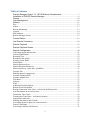
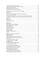
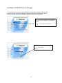
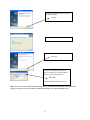
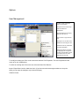
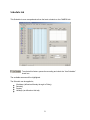
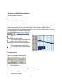
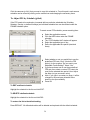
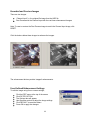
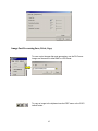
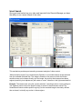
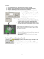
2007 Remote Manager Manual Revision 1.0 2 Table of Contents Remote Manager Version 7.2.1.0718 Minimum Requirements.......................................7 Installation of DIGIOP Remote Manager .............................................................................8 Options ....................................................................................................................................10 User Management.................................................................................................................10 Network ...................................................................................................................................11 Play ..........................................................................................................................................12 Sensor.......................................................................................................................................13 Remote Monitoring ..................................................................................................................13 Joystick ....................................................................................................................................14 Miscellaneous ..........................................................................................................................14 Remote Manager Screen ..........................................................................................................15 Connect Button ......................................................................................................................16 Live Remote Connection ......................................................................................................18 Remote Playback ..................................................................................................................19 Remote Playback Screen ....................................................................................................19 Remote Configuration...........................................................................................................20 Video input status and selection ..............................................................................................21 Camera identification ...............................................................................................................22 Recorded View.........................................................................................................................22 Recorded video quality ............................................................................................................23 Security Screen Mode ..............................................................................................................23 Watch Mode .............................................................................................................................23 Motion Detection Area ............................................................................................................24 Motion Detection Sensitivity ...................................................................................................24 Motion Sensitivity “quick start” guidelines .............................................................................25 Network Tab ............................................................................................................................26 Enabling network connectivity ................................................................................................27 Network Settings (EDIT) .........................................................................................................27 Network Adaptor List ..............................................................................................................27 IP Address ................................................................................................................................27 Gateway ...................................................................................................................................27 DNS..........................................................................................................................................27 Additional Network Options ....................................................................................................28 Remote Event Notification ......................................................................................................28 Remote Connection Time Limit – refer Event Notification list ..............................................29 Auto Disconnect on no activity after: ......................................................................................29 Connection Time Limit ............................................................................................................29 Transmission Time Limit – on Sensor activation. ...................................................................29 Sensor and Control tab .............................................................................................................30 Enabling the Sensors and Controls ..........................................................................................30 Associating Sensors (inputs) to create an action......................................................................31 Sensor Time Range ..................................................................................................................31 Associating Cameras with Sensors ..........................................................................................32 3 Associating PTZ Presets with Sensors .....................................................................................32 Associating Relay Outputs (Controls) to Sensors....................................................................32 Setting Sensor Record Time ....................................................................................................32 Miscellaneous Options for Sensors ..........................................................................................33 Recording Mode – Normal or Optimized ................................................................................33 Initiating a Camera(s) to record on a Sensor trigger ................................................................34 Sensor Type .............................................................................................................................35 Sensor Alarm ...........................................................................................................................35 Sensor 16 (last sensor input on system) used for shut down ...................................................35 Sensor 16 Auto Shut Down......................................................................................................35 Causing a Sensor trigger to move a camera to a pre-defined PTZ position. ...........................36 Causing a Sensor trigger to activate a Camera and a Control (output relay). ..........................37 PTZ Tab ...................................................................................................................................38 Enable PTZ ..............................................................................................................................39 PTZ Protocol ............................................................................................................................39 PTZ Camera Address ...............................................................................................................39 Color Tab .................................................................................................................................40 Display Tab ..............................................................................................................................41 Enable/Disable Camera Recording ..........................................................................................42 Password Protected Recording ................................................................................................42 External Monitor ......................................................................................................................43 Recording Resolution...............................................................................................................44 Frames per second....................................................................................................................44 Display Division ......................................................................................................................45 Adding a sequence ...................................................................................................................45 Modify or Clear a sequence .....................................................................................................45 Default......................................................................................................................................45 Display Division Rotation Dwell Time ...................................................................................46 FPS/Resolution tab...................................................................................................................48 Pause Recording.......................................................................................................................49 FPS Settings per Camera (by Resolution) ...............................................................................49 Allocating FPS and Resolution to each camera .......................................................................50 Schedule tab .............................................................................................................................51 To create a schedule for a camera ............................................................................................52 To define the time on a schedule .............................................................................................52 Recording modes .....................................................................................................................52 To Adjust FPS by Schedule (global) .......................................................................................54 To EDIT a defined schedule. ...................................................................................................54 To DELETE a defined schedule ..............................................................................................54 To restore the list to the default setting. ...................................................................................54 Defining a HOLIDAY for the Schedule ..................................................................................55 Image enhancement option buttons .........................................................................................63 Recorded and Preview Images .................................................................................................64 User-Defined Enhancement Settings .......................................................................................64 Image Post Processing Save, Print, Copy ................................................................................65 View Search Process (during SmartSearch) ............................................................................67 4 Sensitivity (for SmartSearch) ...................................................................................................68 SmartSearch - Search ...............................................................................................................68 Quick Search ............................................................................................................................68 Start the SmartSearch Process .................................................................................................69 Search Next Movement............................................................................................................69 Stop Search ..............................................................................................................................69 SmartSearch Result Event List ................................................................................................69 Zoom (for playback only) ........................................................................................................70 5 DIGIOP Remote Manager is a command and control software application designed for use with enterprise, remote and network applications. Remote manager allows users to remotely access, search, browse, display and transfer stored video/image files to a remotely connected workstation(s). Additionally, users may simultaneously view, search and archive up to 24 video channels, control access through administrative and user level password assignments, remotely configure DVR and individual camera settings and receive notification of events such as alarm, motion detection and video loss. Command & Control Software Solution for Enterprise, Remote and Network Applications Remotely View, Search & Archive up to 24 Channels Integrated Web Browser Provides Easy to Use Interface for Search & Retrieval Triplex Functionality allows Users the Ability to View Live, Search Recorded Data and Back-up Video/Image Files Simultaneously Remotely Configure DVR and Individual Camera Settings Control Access via Administrative and User Level Passwords Receive Remote Notification of Events Including Alarm, Motion and Video Loss Smart Search Functionality Allows Retrieval of Specific Information Contained Within Video Frames 6 Remote Manager Version 7.2.1.0718 Minimum Requirements The minimum requirements to run this software are: S-Class CPU: 2.0GHz+ (Celeron/P4/AMD) Memory: 512MB Video Memory: 32MB+ (1024 x 768 32 Bit) Support Direct Draw and GDI Direct X 8.1+ Disk Space: 300MB+ LAN: 10/100/1000 Network OS: Windows 2000 w/SP4 or XP Home or Pro w/SP2 H-Class CPU: 3.0GHz+ (Celeron/P4/AMD) Memory: 1024MB Video Memory: 128MB+ (1024 x 768 32 Bit) Support Direct Draw and GDI Direct X 9.0+ Disk Space: 300MB+ LAN: 10/100/1000 Network OS: Windows 2000 w/SP4 or XP Home or Pro w/SP2 ** Results May Vary If Using Nvidia Riva TNT2 & SiS Video Chipsets. Compatible Server Software: DIGIOP Server Version 7.2.0.0601 or DIGIOP Server Version 6.11 7 Installation of DIGIOP Remote Manager 1.The following screens appear when DIGIOP Remote Manager installation CD is inserted. If the screens don‟t appear automatically, open disk1 folder from the supplied CD and run Setup.exe. Follow the program installation instructions as shown on the screen. When you inert the disc supplies with Your DIGIOP the screen to the left will be displayed. To install Remote Manager Click on the Remote Manager icon This screen will come up Click on Install 8 DIGIOP Remote Manager Wizard will come up, to install the software Click Next The Install Wizard will Install the software The Install Wizard complete box will come up Click Finish When the software Wizard has completed the installation The Remote Manager Login will appear. A Password has not been installed at this time. Leave Password Blank and Click OK The Remote Manager Screen will come up Note: The user functions within Remote Manager are on a client based relationship meaning that the rights you assign to the user will ONLY be applicable to that user on that workstation only. 9 Options User Management To Add or modify users Click Tools, choose Options The options screen will come up select the folder User Management Click Add and the User Property (New) box will come up User ID: Enter a Login ID for the user Description: You can enter more detailed info concerning the user Password: Enter any combination of numbers and letters Select the functions for the user by highlighting the unsupported functions and Click add. This will move the function over to the Supported Function side To modify an existing user Click on the user name and then Click Properties. The User Properties box will come up for your modifications To delete an existing user Click on the user name and then Click Remove Import Export Save User list, Adds User list in (If you have several remote agent stations to set up the same you can save the settings to a pin drive and import) .DUA file format 10 Network Network Time Out provides you with a place to set the time that Remote Manager will stay connected with no activity Live setting is setting the time interval for reconnecting in the event that there is a network interruption. If you click Advanced you will be provided a box to select Try reconnecting continuously for network server error Buffering Time provides the ability to smooth out the video being received by providing a buffer Modem provides you with the ability to setup a modem for communication to your DIGIOP units. When you click on Config another box like the example below will appear. Choose the modem you wish to use from the provided list. 11 Play Video Play Setting Use Direct Draw is used as a useful tool which Remote Manager utilizes to allow for smoother graphics transfer and communication to stream video. Show Last Video in Playback End is used when you want the last played video clip to populate within the Remote Manager viewing area. Video Caption Font Size sets the text size within the video screen. Voice Play Setting Disable Voice removes the ability to hear sound. Play Voice of All Screens Simultaneously will playback all incoming audio channels at the same time. If this option is not checked then audio will only playback for the channel that is selected. VOD File Save Folder The VOD File Save Folder is the directory that video will be stored in when the VOD button is selected during playback. High Quality Printing Mode will increase the quality of the image to be printed. 12 Sensor Sound Effect Duration Choose the time frame in which a Sound Effect is audible for a Sensor Activation Event. Remote Monitoring Receive Remote Event: Enables the following options General Event: when a system event occurs that is not in the category of the other items mentioned in this area. Sensor Event: when a Sensor is triggered on a unit Reboot Event: when a unit does an improper restart Video Loss Event: when a unit detects loss of Video signal Automatically Connects Sensor Occurrence Sites: when Remote Manager starts it searches for events for units in its site list. Use User-Defined Event Sound Effect is a sound file that can be associated with Events besides Sensor Events. Remote Monitoring Remote Monitoring is the option to enable Monitoring choices. Monitoring Interval is the amount of time that the Maximum number of retrial is the amount of times the system will attempt to Keep event log files allows for the system to keep the information shown in the Event Panel of main screen for a defined time. 13 Joystick Set up the operation for the joystick Works with all joysticks that can load onto the Remote Manager workstation. Button 1: Hot Function Option Button 2: Hot Function Option Button 3: Hot Function Option Button 4: Hot Function Option All of the Hot Function Options pertain to PTZ functions and controls and the available options within this setting are: None, Zoom, Focus, Iris, Presets 1 – 8. Miscellaneous Panorama Playback Enable panorama playback mode is to enable a single screen across all views with Remote Manager. Default Caption Show server name is to display unit information in the video screen. Show channel title is to display camera name in the video screen. Show date and time is to display date/time information in the video screen. Show status is to display what state it is in when playing in the video screen such as Pause, Live, or Playback. Miscellaneous Select the first connectible camera when a camera is not available for display; the Remote Manager will show the first available camera in its place within the video screen. Always Download XML When Application Starts always checks the Server for latest Active X controls. Recorded File Save Folder is the directory that video will be stored in when video is saved from Remote Manager‟s Site Save 14 File option. Remote Manager Screen The Function of Each Button is for the most part self explanatory. In the following pages the functionality of each part of the software will be explained in detail. 15 Connect Button This is where you set up the DIGIOP units that you want to view remotely. To Add a Site Click the Connect Button ‘Site/File Open’ Screen comes up Click Add ‘New Open (New)’ Window Opens . Select „Connection Type‟.(LAN,Modem) Enter the name of site (For Example: Branch Name, Store Number, etc.) Enter the sites‟ IP address or phone number. Enter User ID and Password for DigiOp connection. Enter the desired camera channel number. A detail description of the selected site can be entered on „Description‟. Click “OK” to confirm the entries <Remove> A site can be deleted by selecting the desired site to be removed and clicking “Remove” A Caution box will come up click Yes 16 <Properties> Checks and modifies the entered user Information <Export> <Import> Save site list, Adds site list in (If you have several remote agent stations to set up the same you can save the settings to a pin and import) .DAC‟ file format 17 Live Remote Connection Live Mode Select desired sites (Dell S 120-16) to connect to. Select „Live‟ in “View Type”. To view sites on channels other than those in the list, select the desired channel from the „Channel‟ box in “Connection Option” at the bottom of the screen. Click “OK” to connect to the server. Multi-Site Connection To connect to multiple sites at the same time, select desired sites in the list and press “OK”. The multiple sites can be selected at once by clicking on the sites while pressing down on <Ctrl> or <Shift> button. * Simultaneous access to more than one site is available only through the LAN. The modem connection allows only single site access per connection. Live Video Screen Disconnect from single channel Disconnect All Channels Activate 2 way Audio Start Record to prespecified drive The live view screen once connected gives you the ability to Remotely View and control your DIGIOP. Most functions available on the DIGIOP Server are also active from the Remote Manager Software. Screen Quadrant Selection (Click screen again to move to next camera or group of images Zoom Click the Zoom button and then click the video you want to Zoom in on Connection Panel Provides a quick connect for live or recorded video drag and drop the recorder to the first screen for live video. Click VOD and select time and date then drag and drop recorder to first screen for recorded video PTZ Camera Control gives you the ability to remotely control the Pan Tilt Zoom and Preset Functions of a PTZ Camera 18 Relay Panel Allows you to remotely activate Relays that are set up on the server Remote Playback Remote Playback Select a site (DigiOpG2 DVR) that you want to connect to Select „Remote Playback‟ in “Connection”. Select desired date and time to search. To view sites on channels other than those in the list, select the desired channel from the „Channel‟ box in “Connection Option” at the bottom of the screen. Click Intelli search for 24 hour or leave blank for 1 hour Click “OK” to connect to the server. Remote Playback Screen Remote Playback screen functions the same as live with more functionality. Remote Playback once connected gives you the ability to Remotely View and control your recorded video from your DIGIOP. Most functions available on the DIGIOP Server are also active from the Remote Manager Software. Intella Search Panel gives you a graphic display of the video captured for the time period. The blue areas show the recorded video slide the red line to the time you want to view and push play Video Control buttons are active on playback from left to right Go to start, fast backwards, pause, play, one frame forward, fast forward, go to end The Event Panel displays incoming events from DIGIOP DVR‟s 19 Remote Configuration Remote configuration provides you with the ability to make administrative changes to the DIGIOP unit from a remote location. The configuration parameters are similar to the DIGIOP Server software. Please refer to the G3 Service Manual for detailed instruction. The System Tab is different in remote manager and a new Tab called Time is added they are covered below. To access remote configuration click on tools, remote configuration. When the Remote Configuration screen comes up click on connect. That will bring up a list of the units that you have programmed into Remote Manager. Choose the Unit that you want to configure from the list or enter the site name in the provided box. The password you must enter on this page is the administrator password for the unit that you are connecting to. Then click Connect 20 Camera Tab Video input status and selection The camera icons at the top of this tab identify the channel input status. Camera source connected to channel 1 video input and selected for configuration. While this icon is highlighted the options displayed are related to this camera. Camera source connected to channel 2 but not currently being configured. To switch to this camera, click on this icon. No video source connected to channel 26. 21 Camera identification The descriptive name entered here will appear on the main screen and the RemoteManager software as an identifier for this camera. Be as descriptive as possible to avoid confusion. The name can be entered directly into the text box using an external keyboard or by clicking the on-screen keyboard icon and using the mouse. Recorded View The selected camera will appear in the “Current Recorded View”, assuming the System is still recording that view. If the System recording has been paused, a default image will be displayed. If the System is set up for motion detection, any detected movement will be highlighted on the image as white squares (this feature varies between System models and software versions). The current kbps and estimated HDD storage is also repeatedly updated. These are only estimates, based on current rates and settings (this feature varies between System models and software versions). 22 Recorded video quality This slider control enables the operator to adjust the level of compression based on the selected compression type (e.g. MPEG, MPEG4, H.264). Moving the slider to the far left will produce small files of low resolution to maximize hard drive storage capacity. Moving the slider to the far right will maximize the quality for scrutiny later but will consume more hard drive space. The file size impact is indicated by the “current kbps” update (see above) and can also be monitored on the RemoteManager software. Security Screen Mode Records images from a camera without displaying the images to the current Operator. In this mode the Operator will only see the default image on the screen with the message “Security Screen” in the top left of the image. Each camera can be individually configured for this mode. In this mode the images are not streamed to Remote Viewing applications. Watch Mode A camera configured for “Watch Mode” will NOT be recorded and can only be used for live surveillance. When selecting this option the image on the CAMERA tab with change to the default image as it is no longer being recorded. In this mode images are not streamed to Remote Viewing applications. If the mode is changed to “Watch Mode” during remote viewing a message will be displayed on the remote viewing application and the image will freeze. 23 Motion Detection Area The incoming video can be used to trigger recording. This option only functions if the Continuous/Motion record mode is set to Motion. Do this by clicking the CONTINUOUS icon on the lower right of the CAMERA tab screen (unless already set to MOTION). There are two available modes of motion detection: 1. Monitor the entire image for motion 2. Operator-defined “motion sensitive” areas on an image. Only when these defined areas detect motion will the System start recording this camera e.g these areas can be positioned over doors, windows, parking areas, etc. Operator-defined “motion-sensitive” areas can be added to the right-hand image on the CAMERA tab using the left mouse button and removed by using the right mouse button. Double-clicking the image will fill the entire image with motionsensitive areas so the Operator can remove rather then add sensitive areas. If errors are made, the Operator can clear the entire screen and start over by checking then unchecking the “Cover Entire Area” check box. A total of 300 motion-sensitive areas can added. Motion Detection Sensitivity This slider with define the amount of movement (motion) required within motion-sensitive areas before the System recognizes it as an activation trigger. If the camera is monitoring a distant image and the expected movement is very slight, the sensitivity needs to be very high. If the image is a doorway and only people are to be detected rather then small pets, the sensitivity can be very low. 24 Motion Sensitivity “quick start” guidelines . 1. Entire Movement: When the entire body moves. 2. Partial Movement: When only the arms or legs move. 3. Movement Speed: Approx. ±20 compensation of recommended sensitivity value (High speed : max. +20, Low speed: max. -20). 4. Number of Persons: If the number of persons on the screen increases, the motion can be detected at a lower sensitivity level. Adjust the sensitivity value accordingly. Note: If the System is to record in low light conditions with poor illumination, cameras may try to compensate resulting in image noise which will trigger the System to record and waste hard drive storage unless Sensitivity is set to a lower position on the slider. 25 Network Tab Edit System IP Address Enable Network Connection Enter IP Address of PC operating Remote Manager Allows you to control the time for remote connection Maximum time for Remote Connection Auto Disconnect after max time period 26 If the System is to be used on a Local Area Network (LAN) to interface with another application, or so it can be accessible via a web browser or Remote Manager software, then the IP address of the System must be fixed. Enabling network connectivity Enable network connectivity by checking the “Enable Network” check box Network Settings (EDIT) Click the EDIT button to open the “Network configuration settings” window. The three critical items are the Adaptor (leave as default), the System IP Address and Subnet Mask. Network Adaptor List The default adaptor value is normally okay but an alternative maybe selected using the drop-down list. IP Address To enable other applications to reliably access this System, a fixed IP address is required. Enter the System IP Address and Subnet Mask into the appropriate boxes in the correct format (xxx.xxx.xxx.xxx). Tip: To identify the Subnet Mask, check the network details of your Remote PC configuration. You can go to START>RUN, type in CMD <then press enter>, then at the prompt type in IPCONFIG <then press Enter>. The PC IP Address will appear with the Subnet Mask. Copy the number of the Subnet Mask to the System Subnet Mask. Gateway If the LAN has access to external networks a gateway can be entered but is not necessary. DNS Enter DNS details as necessary or leave as default. Note: To access the internet from the DIGIOP a DNS server must be defined. 27 Additional Network Options Remote Overlay Control: Allow Syncronization: Allows the PC running remote manager to be synchronized with the server Remote Event Notification For Remote Manager Users to receive events (alarms) from the System, their PC IP Address must be registered under the “Remote IP and Phone Number” list. There is a limit of 10 that can receive notification. *DIGIOP Systems do not come standard with diallers/modems; however DIGIOP Systems do support US Robotics model #5633. The ADD button brings up the ADD window which prompts you for the Remote Manager PC IP Address to be added. To DELETE a PC, highlight the item on the list and press DELETE. 28 Remote Connection Time Limit – refer Event Notification list Auto Disconnect on no activity after: The Remote Manager PCs that have their IP address entered in the "Remote IP and Phone numbers” list will be automatically connected by the System when a sensor event occurs (up to 32 connections). "Connection time limit when sensor occurs" determines how long this connection should exist. Time range is up to 20 minutes. Connection Time Limit See above. When a System has made a connection to a remote PC (after a sensor trigger event), this setting disconnects the remote PC again after the specified time interval. For unlimited connection time uncheck this option (default). Time limit range is up to 120 minutes. Transmission Time Limit – on Sensor activation. Video will stream to Remote Manager on sensor activation. The time that video streams may be different than the Sensor Record period (see Sensor and Controls tab). To limit the transmission time select the desired period from the drop down list. The options range from 10secs to 10mins in various increments. “No Limit” is also an option which means the video will continuously transmits until it is manually disconnected. 29 Sensor and Control tab Most of the functions on this tab are selected by clicking the icon image. A second click will deselect that function. A greyed out icon implies the item is not available to configure, or has not yet been configured on a different tab. The term “sensor” is interchangeable with “input” and the term “Control” is interchangeable with “output” or “relay output”. Generally an input is connected to a dry clean set of normally open (N/O) or normally closed (N/C) contacts. No „end of line resistors‟ or “balanced input resistors‟ should be used. The exception is the H480R-16 (D1) unit (EXTIO-16) that uses an external I/O device that requires a 2.2KΩ resistor (refer to EXTIO-16 Manual). Enabling the Sensors and Controls This Sensor and Controls tab defines the function of the INPUTS and OUTPUTS of the System. Unless the “Enable Sensors and Controls” check box is checked, the I/O will not function as expected. 30 Associating Sensors (inputs) to create an action The available sensors (inputs) are highlighted in blue across the top of the tab window. If the selected sensor is available, its icon will turn yellow. The number of sensors varies from each model of DIGIOP. Note: For this discussion we are going to use the S120 unit that has 16 cameras, 4 sensor inputs and four control outputs. Sensor Time Range Sensors can be disabled by schedule as defined on the top right of the Sensor and Controls tab. By default sensors and controls are scheduled for 24 hour operation (assuming they have been „enabled” – see above) To change the default, simply drop the “From Hour” list and select the “enable sensor time” and then drop the “To Hour” list and select the “disable sensor” time. This schedule is applicable for a full 7 day period. Note: For comprehensive scheduling TOOLS>CONFIGURE>SCHEDULE tab. 31 of sensor monitoring go to Associating Cameras with Sensors After selecting a sensor you can choose which camera to associate with. Associating PTZ Presets with Sensors After selecting a sensor and a PTZ camera you can choose which Presets to associate with. Associating Relay Outputs (Controls) to Sensors After selecting a sensor a control can be configured to activate. Setting Sensor Record Time Choosing Sensor Active Duration will cause the associated camera to record for the duration of sensor activation. Choosing Predefined Time allows a user set a range of recording time from 3 seconds to 5 minutes once initiated by a sensor. 32 Miscellaneous Options for Sensors Display mode - When this mode is selected and the sensor (corresponding to a selected camera) activates, the system automatically maximizes the image display of that camera for the duration of the preset “Display Mode Freeze after sensor,” regardless of the display mode selected. Motion Sensor - This enables a motion detection activation to be displayed to the User rather then just recording the event. Recording Mode – Normal or Optimized This mode selection is only applicable to sensor activiations and NOT related to motion detection activations. This will attempt to take any available frames (up to 29 additional) and apply them to that channel during that alarm period. Optimize Frames is only available in HClass units.* This means, if the camera channel is selected to record on sensor (S) or motion/sensor (M,S) modes, or Continuous/sensor (C/S) the record will be “Optimized” at the time of the sensor trigger. The resultant recording will be at the maximum available fps for the duration of the sensor alarm (does not include the pre-alarm period). 33 Example: If a camera is recorded at 5fps and the “Optimize Frames Per Second” option is checked, then when the sensor is triggered the camera will be recorded at 25fps (if available) till the end of the “Sensor Recording Time” where the fps will return to 5fps. If the User is viewing a multi-divisional display (split screen), the alarmed channel will enlarge to fill the screen. Once the alarm period has expired, the image will return to the original split screen mode. When “Normal” is selected, the resultant recording from sensor activation will be at the fps set by the Operator. Example; if that channel is set for 5fps recording continuous or motion, it will stay at 5fps on sensor activation. Under the “Normal” mode, a sensor activation will not make any changes to the image. A red border round the image will alert the Operator to the image in alarm. Initiating a Camera(s) to record on a Sensor trigger To associate a sensor (input) with a single camera, select the available sensor, then click the available camera. This will cause the camera to start recording when the sensor is triggered. A single sensor can be associated to many cameras, so a single sensor input can cause multiple cameras to record. A camera may also be associated with more than one sensor in which case it will start recording when any of its associated sensors are triggered. Scenario A: Sensor 1 is associated with Camera 1 and Camera 2, and Sensor 2 is also associated with the Camera 1 and Camera 2. Triggering Sensor 1 or Sensor 2 will result in both cameras recording. Scenario B: Sensor 1 is associated with Camera 1 and Camera 2; Sensor 2 is associated with Camera 1 and Camera 3. Triggering Sensor 1 will cause Cameras 1 and 2 34 Sensor Type Specify whether the sensor is of the “normally open” type (i.e. the sensor will close the circuit on activation), or of the “normally closed” type (i.e. the sensor will open the circuit on activation). Sensor Alarm This provides an audible alert for sensor activations. When this is selected the System will beep on sensor activation. Each sensor can be individually set. Sensor 16 (last sensor input on system) used for shut down Sensor 16 Auto Shut Down In the case of power failure, an Uninterruptible Power Supply (UPS) is highly recommended which will protect against surge, spike protection, and momentary power loss. If the UPS provides a relay output for power protection, this can be wired to notify the Unit to start the auto shut down procedure. This will eliminate a system power off and reduce the possibility of system damage that often occurs with power disruptions and prevent a system recovery. The system will close down after the time period selected and it will take approximately one minute to do so. For example if your UPS lasts for 5 minutes, select a period of 3 or 4 minutes to allow for the extra minute. When power is provided via the UPS then the system will start up and go back into a record mode. 35 Loss Detection Parameters Video Loss Detection - Turning this setting ON will take control of your last output control relay, activating it for one to two seconds whenever the system detects video loss on any connected camera. This is a “global” setting across all connected cameras. Recording Failure Alarm – If, for any reason, a video channel fails to record to the hard drive (e.g. HDD damage) the second to last control relay will activate attributing a recording failure. An external device can be connected to notify an alarm panel or siren of the recording failure. Note: System events will be logged to the Event Log. Scenario A: Sensor 1 is associated with Camera 1 and Camera 2, and Sensor 2 is also associated with the Camera 1 and Camera 2. Triggering Sensor 1 or Sensor 2 will result in both cameras recording. Scenario B: Sensor 1 is associated with Camera 1 and Camera 2; Sensor 2 is associated with Camera 1 and Camera 3. Triggering Sensor 1 will cause Cameras 1 and 2 to record. Triggering Sensor 2 will cause Cameras 1 and 3 to record. Causing a Sensor trigger to move a camera to a pre-defined PTZ position. Sensor inputs can be associated with any available camera PTZ preset location. Using our Talon PTZ, up to 127 presets can be selected. Any one of the 127 preset locations can be associated with a sensor input. Note: The Camera PTZ must be enabled (go to the TOOLS>CONFIGURE>PTZ tab) and the PTZ Presets must be defined. 36 Scenario C: Sensor 1 is to swing Camera 1 (PTZ) to the Preset 5 position. To do this; select Sensor 1, select Camera 1, drop down the PTZ list under Camera 1 and click on “5”. This could be just as easily done for multiple cameras. Scenario D: Sensor 1 is to swing Camera 1 (PTZ) to the Preset 5 position and Camera 3 (PTZ) to Preset 127 position. To do this; select Sensor 1 icon, select Camera 1 icon, and select “5” from the PTZ drop-down list under Camera 1. Then select Camera 3, and select “127” from the PTZ drop-down list under Camera 3. Now triggering a single sensor input will cause both Camera 1 and Camera 3 to reposition and record. Causing a Sensor trigger to activate a Camera and a Control (output relay). Sensor inputs can be associated with any available Control output (relay) BUT must also be associated to a Camera. Different Systems have different combinations of sensors vs. outputs. The icons on the Sensor and Control tab will identify the available I/O. The Controls (outputs) are identified by the “Warning Light” icon. Available Controls are displayed as dark grey. A smaller grey Control icon indicates the Control is being used by another System function. A red Control icon indicates the Control is currently selected. To associate a Sensor to a camera and an output relay, simply select the sensor icon, select the camera (and PTZ preset position if required) and then select the Control. As each device is selected, its associated icon will be highlighted. Scenario E: Triggering Sensor 1 will record Cameras 1 and 2, cause Camera 1 to go to Preset Position 2 and cause Relay Output 2 to activate e.g. turn on lighting. 37 PTZ Tab 38 To activate the use of a PTZ on one of the cameras, check the “Use PTZ” check box Enable PTZ The available cameras are highlighted across the top of the window. Camera icons in grey are not available for configuration. If the Operator is to use a PTZ on one of these cameras, select the appropriate camera icon and check the “Enable PTZ” check box. A PTZ camera does not require configuration unless it is to be used from the DIGIOP. PTZ Protocol Once the PTZ is enabled for the selected camera, use the PTZ Protocol drop down box to select the pre-defined protocol to be used. If the specific PTZ is not listed, look for a similar model, or the same manufacturer, and test it. If a special protocol is required, please contact your DIGIOP servicing dealer. PTZ Camera Address Each PTZ on the network will have its unique ID number (which is set via dip switches on the PTZ camera). Enter this number into the software using the on-screen keyboard and press input which will close the keyboard. 39 Color Tab By selecting the camera at the top of this tab, the image content (luminance/chroma) can be adjusted. Each camera image on the system can be customized to enhance the image. For example, if the image colors are too contrasting, the image could be customized to reduce the contrast. The controls are self explanatory. All kinds of effects can be achieved Clicking DEFAULT will bring back the original settings. 40 Display Tab This provides the operator some fundamental control over the display and recording options of the System. A number of items can be selected here on a global scale, but maybe more defined when using advanced features provided on other tabs e.g. Frames per second, compression. 41 Enable/Disable Camera Recording By default all operating cameras connected to the DIGIOP System produce highlighted camera icons, which means they Image 1 Image 2 are being recorded. The greyed out icons represent channels that do not recognize any usable video input (see image 1, cameras 5-16). To disable a camera from recording to the hard drive, click the icon. It will retain its blue numbering and dark outline but To lose its highlight (see image 2, camera 2). On a “real-time” unit, the image will still appear on the main screen, but on the non-real-time display units the camera image will not be present. Password Protected Recording Applying a Password to video and/or audio provides an extra level of security for the encrypted data on the hard drive. A password can be assigned to the video, the audio, or a single password can be used for both by clicking the Same as Video box and entering a password in the Video box. The password can contain up to 50 characters, including lowercase alphabet letters and Arabic numbers. Note: A password is only applied to files at the BEGINNING of the next recorded hour unless recording is stopped and restarted. For example: a new password is selected at 3:20, the password will be used to encode recordings after 4:00. So the images recorded between 3:20 and 4:00 will not be protected with the new password unless recording is stopped and restarted. The password will be required each time recording video is to be watched from the System or any external application. There is no way to recover this password if lost. 42 To use the password option, click the “Password Protected Recording” checkbox. Chose either to have a common password on video and audio or separate passwords using the “Same as video” check box. To enter a password into the appropriate option, click the associated ENTER button. An onscreen keyboard will appear. Type in the password and click INPUT. A second on-screen keyboard will appear for you to verify the password. Re-type it and click INPUT. If the passwords match – all will be well. External Monitor The External Monitor (spot monitor – if available) is the ANALOG monitor plugged directly into the Systems‟ Capture board on the S30 to S240 model DIGIOP‟s. Each DIGIOP model handles the external monitor option slightly differently. S30 – S240 Display tab The external monitor sequences through an Operator-defined sequence of video channels. To create a sequence to be displayed on the external monitor, check the “Sequence” check box and check the cameras to view. Set the dwell time. The Sequence option can be left checked or uncheck to avoid accidental reconfiguration. S480 has a multi screen monitor output that displays the image as seen on the server software screen. H Class DIGIOPs are not equipped with a spot monitor out. It can be purchased as an option which will add a card to the back of the unit that has 4 BNC connectors with one being a multi screen output which will display the images as seen on the server software. 43 Recording Resolution In most cases, these options will only be available while recording is paused. Each System may have different recording resolutions. This is a global setting applied to all cameras when not using the FPS/Resolution tab to define individual camera resolutions. With recording paused, select the resolution for ALL the cameras. Note that these settings will be overridden by any options configured using the FPS/Resolution tab. Frames per second This is a global setting that will affect all cameras if the FPS/Resolution is not being used. (To individually configure each camera for a specific frame rate, enable the FPS/Resolution tab.) The function of this setting control can vary slightly from model to model and between S-Class and H-Class units. The available FPS is based on the compression type, the model of the unit, the number of cameras connected, and the resolution. Changes in these parameters will change the “Maximum Frames” rating. 44 Display Division The multi screen System display is split into divisions where a combination of images can be viewed. For example, if the operator wants to see four cameras at once, they click the button on the main screen and the first four cameras in the sequence are displayed. In this example that would be Cameras 1, 2, 3, & 4). And if the button is clicked again Cameras 5, 6, 7, & 8 will be displayed, and so on. By default the System comes with sequential sequences that can be deleted or modified. Other sequences can also be added. Adding a sequence 1 2 3 4 To add a sequence, choose the desired multi-image screen mode setting from the set of available “Division” icons. A highlighted icon identifies the current selection (example here is 4-way split screen). Click on the camera icons in the desired sequence with which you would like them to appear on the screen. As an example you may want Camera 12 in the #1 division, Camera 3 in the #2 division, Camera 6 in the #3 division, and Camera 1 in the #4 division. Each camera icon will highlight and be added to the text box when clicked. Click the ADD button and the new sequence is added. Modify or Clear a sequence While entering a sequence and an error is made, click either the MODIFY or CLEAR buttons and the system will clear that sequence. Default 45 To default the System back to the original sequence list, press DEFAULT (there is no “undo”). Display Division Rotation Dwell Time Each multi-image screen division mode (e.g. 4way split, 6-way split, etc) can have different sequences of images per screen displayed setup (or use the default). For example the default sequence for a 4-way screen division split is channel 1, 2, 3, 4 but can be customized to display 2, 3, 4, 9. The display can “rotate” (sequence) through the defined screen division setups (see above) by checking this option, or clicking the rotation button on the main screen (these two check options are directly linked and can be activated here or on the main screen). The dwell time can be set to anywhere between one and sixty seconds. 46 Time Tab In most System applications the time of events is critical. System clocks can be individually set or set by a “time server”. DIGIOPTS is a time server application that will synchronize all DIGIOP clocks on a network to a single time. If the System is not on DIGIOPTS the Time tab allows you to manually adjust the time of the DIGIOP 47 FPS/Resolution tab The Frames per Second (FPS) setting controls the number of complete images captured and saved per second and the Resolution controls the image size. Both these settings directly affect the quality of the video recorded and thus the hard drive storage capacity required. The higher the quality of video recorded (size and speed of images), the greater the hard drive storage capacity that is required. This tab allows you to minimize the image quality (and thus, the disk space used) for video considered to be “secondary priority” while maximizing the quality of video considered to be “high priority”, by setting the FPS and Resolution for each of the cameras individually. Note: Only activate this tab if you want to record different cameras using varying levels of quality. For a “global” setting (all cameras) see the DISPLAY tab. Pause the System recording and check the “FPS and Resolution Setting per camera” to activate this feature. Please refer to the steps below for instructions on how to access this tab. 48 Pause Recording By clicking this button an authorized operator can access the System configuration and Pause Recording to allow access into the FPS/Resolution Tab. PAUSE RECORDING: Pauses the recording of all cameras to the hard drive. In most cases it is required to pause the recording to change recording type parameters e.g. fps, resolution, schedule, etc. If no actions have been performed on the system it will return into a record mode after 15 minutes. FPS Settings per Camera (by Resolution) Each System has a set amount of capture capability. This effects the number of images (frames), of a certain size, that can be captured and displayed. Using the up/down arrows beside each resolution size, the Operator can define how the available FPS is allocated to each resolution 49 The image shows a S120 example: The set-up shows that: 120 ips is available for the 352 x 240 resolution but in the example it is set at 0. 120 ips for the 720 x 240 resolution 90 ips for the 720 x 480 resolution but in the example it is set at 0. Allocating FPS and Resolution to each camera Each camera can be allocated a Resolution and a portion of the available FPS for that Resolution (see above). To set-up each camera: Pause the Unit recording (the available cameras are highlighted) Select the camera to be set-up from the available cameras Select the desired Resolution setting. (The available FPS for that resolution will be updated to the left of the resolution selected). Use the slider control to set the FPS for that camera. 50 Schedule tab This Schedule is more comprehensive than the basic schedule on the CAMERA tab. To activate this feature, pause the recording and check the “Use Schedule” check box. The available cameras will be highlighted. The Schedule can be applied to; Workdays (defined as Monday through to Friday) Saturday Sunday Holidays (as defined on this tab) 51 To create a schedule for a camera Click an available camera icon To define the time on a schedule To set the recording mode for a particular time(s) of day, select the applicable cell(s) in the Record Option table. Each cell in this table maps to a time of day and a type of day (e.g. Workday, Saturday, etc.) and a particular camera (i.e. the currently selected camera). Any of the following methods can be used to select cells: Select Click on a row or column header to select the entire row or column Click an individual cell on the schedule Hold down the CTRL key on your keyboard while clicking multiple non-adjacent cells Click and drag across multiple cells Click the ALL button to select the entire schedule Recording modes There are 6 possible recording modes: M Motion Detection M,S Motion Detection AND Sensor triggered recording S Sensor only triggered recording C Continuous recording 52 C,S Continuous AND Sensor triggered recording Note: If a SENSOR is used to initiate recording it can cause other features to be activated e.g. optimized recording rates (H-Class ONLY) can be used, audio alerts, etc. Once the cells on the schedule have been selected, choose a recording mode to be used for the selected time period(s) and camera. The selected “mode” will appear in the cells selected. Here on Monday to Friday between: Midnight to 1am -> Motion detection 1am to 2am -> Sensor trigger 2am to 3am -> Motion detection with sensor trigger 3am to 4am -> Continuous recording at fps 4am to 5am -> Continuous and Sensor trigger (maybe optimized) 5am to 6am -> Camera is OFF (not recorded or visible) Once these are defined, this schedule can be copied to other cameras by clicking the COPY TO button. The COPY SCHEDULE window will appear. 53 Click the cameras (or ALL) that you want to copy this schedule to. From this point, each camera schedule can be refined by clicking on the camera icon and changing the necessary items. To Adjust FPS by Schedule (global) If the FPS needs to be reduced or increased within a particular scheduled day (Workday, Saturday, Sunday, or defined Holidays) an individual schedule item can be created under the FRAME schedule option. To create a new FPS schedule, pause recording then: Select the applicable camera Click the ADD button under the FRAME schedule The “FPS Schedule Add” window will appear Select the applicable type of day Define the applicable time period (start/end times) Select whether or not you would like to use the predefined FPS rate. How? (Under the FPS option), for the question “Do you want to use Adjustable Frame Setting?” select “Yes”. If you have chosen not to use the pre-defined FPS rate, then select a custom FPS rate to be used for the selected time period. How: Adjust the slider (or type a numeric value). Note: If you type in a number too large, it will be changed to the maximum allowable value based on the fps availability. Press OK To EDIT a defined schedule. Highlight the schedule in the list and click EDIT. To DELETE a defined schedule Highlight the schedule in the list and click DEL. To restore the list to the default setting. Press DEFAULT. All defined schedules will be deleted and replaced with the default schedule. 54 Defining a HOLIDAY for the Schedule The Holiday column on the schedule relates to the “holidays” defined under this window. Enter the Holiday description into the DESCRIPTION text box Enter the date (USA format mm/dd) Click the ADD/EDIT button, and the item will be added to the Holiday schedule list 55 System Tab Record: Applies to the DIGIOP server gives the ability to Start, Stop recording and restart the server Notify by email: Is the same as the DIGIOP server refer to G3 service manual for instruction System: Remotely initiate a server system backup Remote Upgrade: Provides the ability to push upgrades to the server software from Remote Manager. Click Install this will bring up the window below. Select the file and click OK Saving Setting Value: Provides the ability to import or export configuration values 56 Print Image When in Remote Playback you can print an image by pausing recording and using the Tools menu choose Print Image. A print screen will come up, choose the desired printer and click OK 57 Back-up Image When in Remote Playback you can Back-up an image by pausing recording and using the Tools menu choose Back-up Image. A Save As screen will come up, choose the desired location to save and click OK 58 Remote Backup To save video clips remotely Click Tools> Remote Backup. The remote screen will come up. Choose the DIGIOP that you want to back up video on and click Connect This screen will come up. Choose the desired camera you want to backup and to the right an hourly display will populate. Using Backup Path: Choose the media you want to backup to. Choose the time frame that you want to backup *note the file size and ensure it will fit on the media Click Save 59 Remote Manager will proceed to write the file to the media 60 Import Backup Video To view the video that has been exported Click the Connect button. The Site/File Open folder will come up. Choose the Local Tab and click Browse. Find the file that has been backed up and click Open. This will populate the file info block Click Add this will apply the video to remote manager When you click OK the video will play 61 Image Post Processing Once you have backed up your video and imported it into Remote Manager you have the ability to adjust the image to optimize the quality To do this: Using the graphical time line on the upper part of the screen, select the approximate time of the images (not critical as the Image Post Editor will display images for the entire file) Click the TOOLS menu button Select the IMAGE POST PROCESSING option. The Image Processor window will open. 62 The Preview panel will enable you to scan images for the entire hour‟s recording, assuming there is an hour of recording. If the camera was set for Motion Detect, there may be less than a full hour of video. At the left most end, the Preview slider will identify the time (HH:MM:SS:1/1000 ref) that the camera started recording in the selected hour. The first images are displayed, frame by frame across the Preview panel. Each thumbnail preview is captioned with the time and 1/1000 frame reference number. Moving the slider will scan through the full hour of images in increments defined by the 1/1000 reference. Image enhancement option buttons These enhancement tool buttons are typical of most video enhancement editors. Enhancements are: Median Smooth conv. Gaussian Gray ST Adaptive Denoise Reset Auto Contrast Enhance Sharpen Conv. Sharpen Edge Sensitivity De-interlace 63 Recorded and Preview Images There are two images: “Channel Input” i.e. the original file image from the HDD file Post Processed is the Channel Input with the real-time enhancement changes Note: To reset or restore the Post Process image to match the Channel Input image, click RESET. Click the buttons below these images to enhance the images. The enhancement buttons provide „stepped‟ enhancements. User-Defined Enhancement Settings To edit the image using finer or course settings; Click the EDIT menu at the top of the screen Click FILTER OPTION The Options tabs will appear Use the slider controls to adjust the image settings Click DEFAULT to reset the sliders Press OK to apply the changes 64 Image Post Processing Save, Print, Copy To save or print images after post-processing, use the FILE menu. Images can be saved in either BMP or JPG format. To copy an image to the clipboard use the EDIT menu or the COPY toolbar button. 65 Smart Search Once you have backed up your video and imported it into Remote Manager you have the ability to run a smart search of the video The SmartSearch (also referred to as “IntelliSearch” or “Museum Search”). This mechanism provides post-recording movement analysis of video content. “Motion sensitive regions” are created by the Operator on a recorded camera image selected from the available recorded files. The image is viewed on the screen to which the motion sensitive areas can be drawn directly onto the image. Any activity that compromises these regions (sensitivity level adjustment) will create an „event‟ reference in the right associated list. Example: The cameras are using the “motion detection” recording mode to view a parking lot. The Operator wants to know the specific time(s) a certain lot was entered or exited. The SmartSearch feature enables specific region(s) on the recorded image to be clearly defined, then reviewed, to identify any motion in those regions. 66 Procedure: 1. 2. 3. 4. On the main search screen, select the date/time to start the search at. Select the camera to be analysed by clicking on the image (border will highlight) Select the SMARTSEARCH option from the Search>TOOLS menu. The above window appears which confirms the camera and the date and time of the search. 5. In the SEARCH options, enter the start and end times for the search. You can use the File Begin and File End checkboxes to set the start and end times to match the available file content. 6. Click the “Go to start” button to view the start point selected. 7. There are two available options for defining search regions: a. “Block” creates a fixed-size square on the image. Up to 20 horizontal and 15 vertical blocks can be added to the image by simply clicking on the image in the desired location. b. “Square” creates a User-defined rectangle. Simply click on Block the image, then drag the mouse to define a “square” region. Multiple squares and rectangles can be created on a single image to create the motion sensitive regions required. Blocks and squares can overlap. Square 8. Select the MOVE option to click on a Block or a Square and move it to a new location. 9. Select the DELETE option to click on a Block or Square and remove it. View Search Process (during SmartSearch) Check the "View Search Process" check box to view all video. When this option is unchecked, only the images that compromise the defined movement sensitive Squares or Blocks at the sensitively level selected are previewed. If no event is found, the image will not change. 67 Sensitivity (for SmartSearch) The sensitivity slider can be adjusted between zero (not sensitive to movement) and 100% (very sensitive to any changes in the defined regions). Set this value depending on the amount of movement you wish to be detected before an event is triggered. The number of events appearing on the event log will reflect the sensitivity of the regions i.e. 100% sensitivity will return more events. SmartSearch - Search By default the System will open with the START TIME as the beginning time of the first recording for that camera, that day (initially the same as “File Begin” time). The END TIME is the time of the end of the file (initially the same as “File End”) when the SMARTSEARCH menu was opened (i.e. does not update real time). These two times can be adjusted to a more defined period by using the up/down arrow buttons, or directly editing the numeric in the boxes. Click the “Go to Start” button to see the image at the start of the selected period. To ignore the defined START TIME and/or END TIME and redefine to the file beginning and/or file end, check the FILE BEGIN and/or FILE END check boxes. The appropriate START or END text box will grey out indicating the override selection. Quick Search The Quick Search feature simply speeds up the process. During casual testing a 10 minute recording processed 20% faster with Quick Search selected. Seach times are typically 60 seconds per 10 minutes of video. In effect the Quick Search ONLY reviews the “index” images and ignores the other images. In a realitively motionless scene this option could save considerable search time. If the Quick Search option not selected, DIGIOP will review every image recorded. 68 Start the SmartSearch Process Search Next Movement Click the “Search Next Movement” button to start the search. The search will pause at the first event (i.e. movement detected inside a defined sensitive region). The found event appears on the list with the start and stop time of the event. Click again to move to the next search. Search All The “Search All” button will erase the current search event list and start the search from the beginning again. The search can be stopped but not paused. Events will be listed by start/end times. Stop Search The “Stop Search” button terminates the search completely (no pause option is available). SmartSearch Result Event List Once the SmartSearch is complete, events can be highlighted in the list and reviewed using the controls above the list: Go to beginning of file Pause playback Playback Fast Forward Go to end of file The Speed slider control only impacts the playback. The playback speed varies depending on the fps the recording was recorded at. At the lowest setting the video will playback at about 1fps. 69 Zoom (for playback only) Choose a record, click the Zoom button, then use the mouse scroll wheel to zoom into the part of the image of most interest (e.g. a square or block region). Press the Play button and the video will playback at that zoom magnification. At the end of the playback, or when a different video record is selected from the SmartSearch list, the zoom magnification will be retained until the zoom button is clicked again and the mouse wheel is used to readjust the image. To disable zoom click the “Go to start” button. The SAVE button will bring up a folder browser. Select the destination folder and choose OK. A folder and file will be created as either BMP or JPG with a name: Folder and file: 20060118-071746.079-01 The name format is: YYYYMMDD – HHMMSS.RRR – Cam# (where RRR is a 1/1000 sec reference number) Once saved, the System will display a confirmation message. The Print button will print the first image of the search event. The ERASE button will erase the list and is the same as pressing SEARCH ALL (see above) 70