1
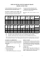
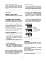
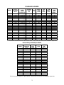
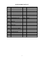
INSTALLATION, OPERATING and SERVICE MANUAL THE INSTALLATION OF THE UNIT SHALL BE IN ACCORDANCE WITH THE REGULATIONS OF THE AUTHORITIES HAVING JURISDICTION. EH Electric Furnace HEAD OFFICE Newmac Mfg. Inc. WAREHOUSE Newmac Mfg. Inc. DEBERT AIR INDUSTRIAL PARK, LANCASTER CRESCENT P.O. BOX 9, DEBERT NOVA SCOTIA, BOM 1G0 PHONE: 902-662-3840 FAX: 902-662-2581 430 SPRINGBANK AVE., SOUTH P.O. BOX 545 WOODSTOCK, ONTARIO N4S 7Y5 PHONE: 519-539-6147 FAX: 519-539-0048 MARKETING / PRODUCTION EMAIL: [email protected] Website: newmacfurnaces.com NOTICE TO HOMEOWNER: READ AND SAVE THESE INSTRUCTIONS 156156 2210047 MAY 2003 MODEL EH CENTRAL ELECTRIC WARM AIR FURNACE GENERAL INSTRUCTIONS It is the responsibility of the consignee of the unit to examine the package for damages and, if found, to note the same on the Carrier's Bill of Lading. The furnace has 240 volt elements and for 240volt, 2 wire, 240 volt blower motor, or 240/120volt, 3 wire, 120 volt blower motor. All furnaces are 1 phase, 60 Hz. The furnace is shipped in one package. This includes the furnace assembly complete with elements, controls, blower, motor and casing, filter rack, filters, thermostat and instruction booklet. kW BTU/hr Model @ 240 Output Static Pressure ins wc Temp Rise °F EH10* EH15* EH20* EH25* EH30* 10 15 20 25 30 34,120 51,180 68,240 85,300 102,360 0.20/0.50 0.20/0.50 0.20/0.50 0.20/0.50 0.20/0.50 35/35 45/45 50/55 60/65 65/70 Model kW @ 240v BTU/hr Output Static Pressure ins wc Temp Rise °F EH9* EH14* EH18* EH23* EH27* 9 13.5 18 22.5 27 30,708 46,062 61,416 76,770 92,124 0.20/0.50 0.20/0.50 0.20/0.50 0.20/0.50 0.20/0.50 30/30 40/40 40/45 55/60 60/65 *D *DS *B See furnace label and this manual for more details. Minimum Circuit Ampacity, A 240V 120/240V 240V 120/240V 4 8 58 63 4 8 84 89 4 8 110 115 4 8 136 141 4 8 162 167 Maximum Circuit Fuse, A 240V 120/240V 60 70 90 90 125 125 150 150 175 175 Minimum Circuit Ampacity, A 240v 120/240v 240v 120/240v 4 8 52 58 4 8 76 81 4 8 99 105 4 8 123 128 4 8 146 152 Maximum Circuit Fuse, A 240v 120/240v 60 60 80 90 100 125 125 150 150 175 Blower Motor A Blower Motor A Air Filter 1@20x20x1 1@20x20x1 1@20x20x1 1@20x20x1 1@20x20x1 Air Filter 1@20x20x1 1@20x20x1 1@20x20x1 1@20x20x1 1@20x20x1 Direct Drive, 1/2HP, 4 speed motor, 240v, or 120v. Delhi G10-8 or Airdex 1020-800-5 DDblower. Direct Drive, 1/2HP, 3 speed motor, 240v. G10-8 or 1020-800-5 direct drive blower. Belt Drive, 1/2HP, 240v or 120v, 1725 rpm motor. G10-8 or 1020-800-5 belt drive blower. EH10 to EH30 elements are 5kW, 240 volts. EH9 to EH27 elements are 4.5kW, 240 volts. Control circuit is 24 volts. Blower motor fuse: 120v - CRN15 type D time delay. 240v - 2 @ TRM8 miniature time delay. CLEARANCE TO COMBUSTIBLES The Newmac EH Electric Furnace may be installed in the up-flow, down-flow, horizontal-left or horizontal -right positions with the following clearances to combustibles: Sides 0" Rear 0" Front (For Servicing) 24" Warm Air Plenum and Duct 0" Locate the furnace to provide: Best heat distribution Shortest supply cable Least interference with present or future plans. INSTALL TO CODE This furnace shall be installed in accordance with the CSA Standard C22.1, Canadian Electric Code, and the requirements of the authority having jurisdiction. These instructions are intended as a general guide and do not supersede local codes. Consult local authorities before installation. POWER CABLE Use 75°C copper supply sized according to the minimum ampacity. This should be connected to a separate fused disconnect switch to power the furnace. Suitable ground must be provided. 1 RETURN AIR AND FILTER RACK The filter rack may be mounted on either side, the bottom or the back of the appliance. Position the rack so that there is easy access to change the filter. HI/ECONO HEAT SWITCH This switch is provided on some models. It is located on the front of the furnace and provides the homeowner with the option of manually increasing or reducing the heating power of the furnace. It can be used to manually switch from "Hi" to "Econo" if less heating power is temporarily desired, depending on the outdoor temperature. This switch can also be controlled automatically by a suitable multi- or two-stage thermostat connected to the W1 (Econo) and W2 (Hi) terminals. Set the switch to "Econo" if a two stage or multi-stage thermostat is used. If a standard thermostat is connected across W1R, a remote switch or an outdoor temperature switch can be connected across OT-W2 to switch from "Econo" to "Hi" as the outdoor temperature drops. Leave the furnace switch in "Econo" if a remote or outdoor temperature switch is used. WARM AIR Before installing the plenum, look into the furnace and check the heating elements to ensure that no damage has occurred and that they are free of foreign material. THERMOSTAT and ANTICIPATOR Should be installed according to the instructions packed with it and connected to the 24 volt terminals on the front of the appliance. The heat anticipator should be set to 0.4 amps. BLOWER SPEED AND STATIC PRESSURE The Newmac EH Electric Furnace is tested and approved by CSA for static pressures of 0.20 to 0.50 ins wc. The 0.20 ins wc static pressure setting is for normal use and the units are factory equipped with the blowers set to provide this. The 0.50 ins wc static pressure setting is for air conditioning. The installer should set the required blower speed - see table below. Set the speed of the belt-drive-blower units by adjusting the motor pulley. Adjust this pulley to give the recommended air temperature rise. OT W2 W1 C G R 2 stage Heat/Cool Thermostat OT W2 W1 C Remote Switch (Optional) SEQUENCE OF OPERATION As the room temperature drops, the thermostat contacts will close and energize the heating element on the first sequencer. After approximately 20 seconds, the first set of contacts in the sequencer will close, bringing on the #1 element. At the same time the circulating blower will start. After approximately 40 seconds, the #2 element will come on. Depending on the model, and if the furnace is set to Hi, #3, #4, #5, and #6 elements will come on in sequence. See below for more information on the Hi/Econo switch setting. When the room thermostat is satisfied, it will break contact. All the elements will turn off in random sequence. The blower will stop when the last element shuts off. Heat/Cool Thermostat OT W2 W1 C Remote Switch (Optional) G R R = 24vac C = 24vac G = Fan Relay W1 = Heat Relay Stage 1 W2 = Heat Relay Stage 2 OT = (R) 24vac G R Heating Thermostat MAINTENANCE To maintain the performance of the furnace, replace or clean the air filter monthly. HOMEOWNER If you, the homeowner, suspect the furnace is not operating properly, or if there is no heat, do not tamper with the furnace. Have a qualified service person check out the furnace installation. BLOWER REMOVAL Turn off the main electricity power supply before servicing the furnace. Open the centre access panel to disconnect the wiring to the blower motor Open the blower access panel. Carefully unscrew the bolt(s) holding the blower assembly in place, and remove the entire blower/motor assembly by sliding it out through the access opening. HI/LO CONTINUOUS FAN SWITCH This is located on the front of the furnace and provides the homeowner with the option of having the circulating blower run continuously at high or low speed. This control does not affect the normal heating and cooling cycles of the furnace. 2 STANDARD BLOWERS MODEL EH10* EH15* EH20* EH25* EH30* EH9* EH14* EH18* EH23* EH27* 0.20 0.50 0.20 0.50 0.20 0.50 0.20 0.50 0.20 0.50 VARIABLE SPEED MOTOR PULLEY (TO) 3-1/4" (0) 3-1/4" (2) 3-1/4" (0) 3-1/4" (2) 3-1/4" (0) 3-1/4" (2) 3-1/4" (0) 3-1/4" (2) 3-1/4" (0) 3-1/4" (2) 0.20 0.50 0.20 0.50 0.20 0.50 0.20 0.50 0.20 0.50 3-1/4" (0) 3-1/4" (2) 3-1/4" (0) 3-1/4" (2) 3-1/4" (0) 3-1/4" (2) 3-1/4" (0) 3-1/4" (2) 3-1/4" (0) 3-1/4" (2) STATIC PRESSURE INS WC BLOWER PULLEY INS BEL T INS DIRECT DRIVE SPEED 6 5 6 5 6 5 6 5 6 5 40 38 40 38 40 38 40 38 40 38 Lo Lo MLo MLo MHi MHi MHi MHi Hi Hi 1,400 1,200 1,400 1,200 1,400 1,200 1,400 1,200 1,400 1,200 900 900 1,100 1,000 1,300 1,200 1,300 1,200 1,400 1,300 APPROX TEMP RISE °F DIRECT 35 35 45 45 50 50 60 65 65 70 6 5 6 5 6 5 6 5 6 5 40 38 40 38 40 38 40 38 40 38 Lo Lo MLo MLo MHi MHi MHi MHi Hi Hi 1,400 1,200 1,400 1,200 1,400 1,200 1,400 1,200 1,400 1,200 900 900 1,100 1,000 1,300 1,200 1,300 1,200 1,400 1,300 30 30 40 40 40 45 55 60 60 65 CFM BELT DRIVE CFM DIRECT DRIVE * = B for belt-drive blower and D for direct-drive blower. Note actual cfm and rise are installation dependent. HIGH CFM (3 SPEED) BLOWER MODEL EH10DS EH15DS EH20DS EH25DS EH30DS EH9DS EH14DS EH18DS EH23DS EH27DS STATIC PRESSURE INS WC 0.20 0.50 0.20 0.50 0.20 0.50 0.20 0.50 0.20 0.50 DIRECT DRIVE SPEED Lo Lo Med Med Med Med Hi Hi Hi Hi 0.20 0.50 0.20 0.50 0.20 0.50 0.20 0.50 0.20 0.50 Lo Lo Med Med Med Med Hi Hi Hi Hi 1,000 900 1,250 1,150 1,250 1,150 1,700 1,450 1,700 1,450 APPROX TEMP RISE °F 30 35 40 40 50 55 45 55 55 65 1,000 900 1,250 1,150 1,250 1,150 1,700 1,450 1,700 1,450 30 30 35 35 45 50 45 50 55 60 CFM DS for direct-drive high cfm 3 speed blower. Note actual cfm and rise are installation dependent. 3 2 WIRING DIAGRAMS - EH30, EH27 Lo Blower Auto L Hi 2 5 2 M1 M3 H M5 M7 H M1 M3 H M5 M7 H M1 M3 H Heat Relay Heat Relay 15S-22 15S-22 15S-21 4 4 M2 M4 H M6 M8 H M2 M4 H M6 M8 H M2 M4 H M6 H 4 WR 90-370 4 G R 5 Primary 24v 3 wire models (120v motor) 120/240v, 1ph, 60Hz 1 Connect to N, L1, and L2 2 No fuse 3 CRN15 type D fuse 4 WR90-372 heat relays 5 120/24v transformer 6 See motor lead colours 60T11 60T11 60T11 60T11 60T11 60T11 OT W2 W1 C Motor H=Black MH(4 spd),M(3 spd)=Blue ML(4 spd)=Orange 6 Lo=Red N or L2 =White 2 5 1 2 3 4 5 6 EH30D, EH27D and DS models M5 H 5 Hi H MH 3 Econo DD Blower Motor ML 6 L2 L1 L2 2 wire 1 N L1 L2 3 wire Heat Blower Auto Econo Hi 3 Heat Hi M1 M3 H M5 M7 H M1 M3 H M5 M7 H M1 M3 H M5 H 15S-22 15S-22 15S-21 M2 M4 H M6 M8 H M2 M4 H M6 M8 H M2 M4 H M6 H 2 5 1 2 3 4 5 6 4 60T11 60T11 60T11 60T11 60T11 60T11 OT W2 W1 C WR 90-370 EH30B, EH27B 2 wire models (240v motor) 240v, 1ph, 60Hz 1 Connect to L1 and L2 2 TRM8 mini fuse 3 TRM8 mini fuse 4 WR90-374 heat relays 5 240/24v transformer 6 See motor lead colours Lo L H L2 L1 L2 N L1 L2 Belt drive blower motor 2 2 wire 1 3 wire 3 fils optional N 4 N Cap G R 5 Primary 24v 2 2 Lo Blower Auto L Hi 2 5 5 M1 M3 H M5 M7 H M1 M3 H M5 M7 H Heat Relay Heat Relay 15S-22 15S-24 4 4 M2 M4 H M6 M8 H M2 M4 H M6 M8 H 4 DS models WR 90-370 1 2 3 4 5 4 G R WIRING DIAGRAMS - EH25, EH23, EH20, EH18 Blower Auto Econo Hi 3 Heat M1 M3 H M5 M7 H M1 M3 H M5 M7 H 15S-22 15S-24 M2 M4 H M6 M8 H M2 M4 H M6 M8 H 2 5 1 2 3 4 5 4 60T11 60T11 60T11 60T11 60T11 OT W2 W1 C WR 90-370 EH25B, EH23B EH20B, EH18B EH20B and EH18B omit element 5 and use 15S-21 in place of 15S-24 Hi 2 wire models (240v motor) 240v, 1ph, 60Hz 1 Connect to L1 and L2 2 TRM8 mini fuse 3 TRM8 mini fuse 4 WR90-374 heat relays 5 240/24v transformer 6 See motor lead colours Lo L H L2 L1 L2 N L1 L2 Belt drive blower motor 2 2 wire 1 3 wire EHxxD = 4 speed direct drive EHxxDS = 3 speed direct drive EHxxB = Belt drive 5 Primary Primaire 24v 3 wire models (120v motor) 120/240v, 1ph, 60Hz 1 Connect to N, L1, and L2 2 No fuse 3 CRN15 type D fuse 4 WR90-372 heat relays 5 120/24v transformer 6 See motor lead colours 60T11 60T11 60T11 60T11 60T11 OT W2 W1 C Motor H = Black MH(4 spd),M(3 spd)=Blue ML(4 spd)=Orange Lo = Red 6 2 5 EH25D, EH23D EH20D, EH18D and EH20D and EH18D omit element 5 and use 15S-21 in place of 15S-24 Hi H MH 3 Econo DD Blower Motor ML 6 L2 L1 L2 2 wire 1 N L1 L2 3 wire Heat optional N 5 N Cap G R 5 Primary 24v 2 2 Lo Blower Auto L Hi 2 5 5 M1 M3 H M5 M7 H Heat Relay Heat Relay 15S-24 4 4 M2 M4 H M6 M8 H 4 EH10D and EH9D omit element 3 and use 15S-21 in place of 15S-24 H MH DD Blower Motor ML 6 3 L2 L1 L2 2 wire 1 N L1 L2 3 wire N 6 WR 90-370 4 60T11 60T11 60T11 G R WIRING DIAGRAMS - EH15, EH13, EH10, EH9 Blower Auto Hi M1 M3 H M5 M7 H 15S-24 M2 M4 H M6 M8 H EH10B and EH9B omit element 3 and use 15S-21 in place of 15S-24 2 5 1 2 3 4 60T11 60T11 60T11 OT W2 W1 C WR 90-370 EH15B, EH13B EH10B, EH9B 2 wire models (240v motor) 240v, 1ph, 60Hz 1 Connect to L1 and L2 2 TRM8 mini fuse 3 TRM8 mini fuse 4 WR90-374 heat relays 5 240/24v transformer 6 See motor lead colours Lo L H 3 L2 L1 L2 N L1 L2 Belt drive blower motor 2 2 wire 1 3 wire EHxxD = 4 speed direct drive EHxxDS = 3 speed direct drive EHxxB = Belt drive 5 Primary 24v 3 wire models (120v motor) 120/240v, 1ph, 60Hz 1 Connect to N, L1, and L2 2 No fuse 3 CRN15 type D fuse 4 WR90-372 heat relays 5 120/24v transformer 6 See motor lead colours Motor H = Black MH(4 spd),M(3 spd)=Blue ML(4 spd)=Orange 6 Lo = Red N or L2 =White 2 5 1 2 3 OT W2 W1 C optional EH15D, EH13D EH10D, EH9D and DS models N Cap G R 5 Primary 24v 24v EH REPLACEMENT PARTS LIST PART NO. DESCRIPTION PART NO. DESCRIPTION 2020008 2020009 1/2 Hp Direct Drive Motor - 4 Speed (120v) 1/2 Hp Direct Drive Motor - 4 Speed (240v) 1/2 Hp Direct Drive Motor - 3 Speed (240v) 1/2 Hp Belt Drive Motor (120v) 1/2 Hp Belt Drive Motor (240v) Variable Speed Motor Pulley 3-1/4" X 1/2" Blower Pulley - 5" (0.5"Wc Static) Blower Pulley - 6" (0.2"Wc Static) Blower Belt - 38" (For 5" Pulley) Blower Belt - 40" (For 6" Pulley) 10-8 Direct Drive Blower assembly complete 10-8 Direct Drive Blower 10-8 Belt Drive Blower c/w 5" pulley 10-8 Belt Drive Blower c/w motor hardware Motor Belly Band assembly, 10" Blower Legs (2) Capacitor - 5uF Capacitor - 7.5uF Heating Element - 5kW, 240v Heating Element - 4.5kW, 240v Sequencer, 15S-21 Sequencer, 15S-22 Sequencer, 15S-24 Fuse Holder (120v motor) for CRN15 fuse Fuse Holder (240v motor) for TRM8 fuse 15A Fuse (120v motor models) CRN15 type D 8A Fuse (240v motor models) TRM8 miniature 24v Transformer (120v model) 24v Transformer (240v model) Cooling Relay (24v coil) WR 90-370 Heating Relay (120v coil) WR 90-372 Heating Relay (240v coil) WR 90-374 240v terminal block (all models) 3090334 4120442 4120438 4120257 4120259 4120260 4120258 4120445 4120437 4120436 4120435 4120439 4120434 Heating Element Blank Cover Front Access Panel (Wiring) Front Panel - Switch Side Panel RH (36" DD models) Side Panel LH (36" DD models) Rear Panel (36" DD models) Blower Access Door (for 36" DD models) Side Panel RH (40" BD models) Side Panel LH (40" BD models) Rear Panel (40" BD models) Blower Access Cover (for 40" BD models) Air Filter Assembly Base Panel 2210047 2010008 Manual Instructions Thermostat (heating only) 2200280 2200258 Switch - Blower, Hi/Lo Continuous Switch - Heat, Hi/Econo 2200130 Thermo-O-Disc 60T11 312301Limit 2180006 20" x 20" air filter 2020003 2240001 2240005 2240006 2240038 2240040 4050280 2040115 2040116 4050281 4110214 2010040 2200121 2200124 2200117 2200118 2200119 2200236 2200282 2200237 2200283 2010022 2010084 2010081 2010082 2010083 2200232 7 NEWMAC Limited Warranty Subject to the following provisions, Newmac Mfg. Inc. ("Newmac") warrants the heating unit under normal use and repair against defects in workmanship or material for a period of one year from the date of installation. Under this warranty, Newmac will replace or repair any defective part at no cost or expense to you except for the cost of delivery and labour in the removal of the defective part and the installation labour of the replacement part. This warranty is void if the unit is not installed, operated, maintained, and cleaned according to the owner's manual. The heating unit must be installed by a competent, qualified installer in accordance with our installation instructions, applicable codes and the National Warm Air Heating and Air Conditioning Association Standards or generally accepted equivalent standards. The warranty is void if any alteration is made to the heating unit without written authorization by Newmac. This warranty is the only warranty made by Newmac. Newmac does not authorize any person or company to provide any other warranty or to assume any further obligation in connection with the sale of this heating unit on its behalf. This warranty shall not apply to damage of the heating unit caused by misuse or failure to maintain the heating unit properly. This warranty does not apply to the installation or wiring not integral to the heating unit. The operation of the heating unit in a corrosive atmosphere (such as concentration of acids or halogenated hydrocarbons) is considered misuse and voids this warranty. This heating unit must be used and cared for in accordance with the instruction manual. The purchaser is responsible for required periodic maintenance such as changing or cleaning air filters and lubrication of components. See instruction manual for details. Newmac shall not be responsible for any consequential damage however caused whether by a defect in the heating unit or any part thereof warranted hereunder or by the negligence of any person. If the heating unit requires service, contact the dealer who installed the equipment originally, or an alternate qualified and registered heating dealer or electrician. As stated herein, Newmac does not assume responsibility for costs of delivery and labour involved in the replacement of defective parts. Unless otherwise directed by Newmac, defective parts must be returned to the Newmac plant; freight prepaid. Collect charges will not be accepted. Replacement parts will be supplied F.O.B. our factory. Whenever requesting service, please be sure to give the model and serial numbers located on the rating plate of your heating unit. This warranty is not effective unless the warranty registration card is properly filled out with all of the required information and received by Newmac at the address below within thirty (30) days of the installation date. Keep this warranty certificate and the instruction manual for future reference. Warranty Registration PLEASE PRINT OR TYPE Owner's name . . . . . . . . . . . . . . . . . . . . . . . . . . . . . . . . . . . . . . . . . . . . . . . . . . . . . . . . . . . . . . . . . . . . . . Address of Installation . . . . . . . . . . . . . . . . . . . . . . . . . . . . . . . . . . . . . . . . . . . . . . . . . . . . . . . . . . . . . . . Date of Installation . . . . . . . . . . . . . . . . . . . . . . . . . . . . . . . . . . . . . . . . . . . . . . . . . . . . . . . . . . . . . . . . . . Dealer's name . . . . . . . . . . . . . . . . . . . . . . . . . . . . . . . . . . . . . . . . . . . . . . . . . . . . . . . . . . . . . . . . . . . . . . Dealer's address . . . . . . . . . . . . . . . . . . . . . . . . . . . . . . . . . . . . . . . . . . . . . . . . . . . . . . . . . . . . . . . . . . . . Furnace serial number . . . . . . . . . . . . . . . . . . . . . Furnace Model Number . . . . . . . . . . . . . . . . . . . Newmac Mfg. Inc, P.O. Box 9, 208 Lancaster Crescent, Debert, Nova Scotia, Canada, B0M 1G0 8