1
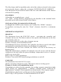
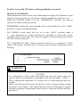
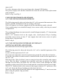
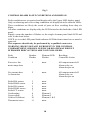
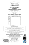
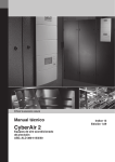
INSTALLATION INSTRUCTIONS
ELECTRIC
WARM AIR FURNACE
BY
IMPACT DISTRIBUTION
Save these instructions for reference
This furnace must be installed by a certified installer
and where required by law, a licenced technician.
FOR SERVICE CALL:
INSTALLATION INFORMATION
_________________
_________________
Qualified Contractor
Telephone Number
_________________
_________________
Unit Model Number
Unit Serial Number
_________________
Date of Installation
MANUFACTURED BY
SUMMERAIRE MANUFACTURING
EXCLUSIVELY FOR
IMPACT DISTRIBUTION
1
INSTALLATION
GENERAL INSTRUCTIONS
ALPHA series electric furnaces are designed, built and inspected to provide
safe and dependable operation when properly installed in compliance with all
National and Local Codes.
The Alpha series of warm air electric furnaces are available in the following
models; 10kW,15kW,18kW, 20kW, 23kw and 27kW outputs .
ELECTRICAL
All electrical equipment and wiring shall be installed following the requirements
Canadian or U.S.A. National Codes.
These electric furnaces require 120/240 vac, 1 phase , 60 Hz – 3 wire power
supply (C/W neutral).
LOCATION
The furnace shall be centrally located in relation to the outlet registers, with
suitably sized warm air ducts, for improved heat distribution.
MULTI POSITION
Alpha series electric warm air furnaces can be installed for vertical, horizontal, or
down flow operation.
NOTE: An optional “ DownFlow “ base shall be installed with units over
23 KW. All panels / doors must be secured in place prior to starting unit.
A filter frame C/W disposable filter is supplied to suit 20 x 20 x 1 filter.
2
The filter frame shall be installed on the side of the cabinet selected for the return
air to enter the furnace; either side or bottom. NOT IN BACK OF CABINET.
Four knockouts are provided on each of the two sides and bottom of the furnace
to locate R/A opening.
FEATURES
All models are completely pre - wired.
All “ field “ wiring shall be completed by the Installer to the terminal block
provided on the main control board in the furnace.
INSTALLATION CLEARANCES FURNACE
As shipped the ALPHA series furnaces are Certified for “ZERO” clearance.
To facilitate servicing the unit, the “Front” clearance should be a minimum
of 24”.
OPERATING SEQUENCE
HEATING
The thermostat closes the R-W1/W2 circuit, - activating the controller and
elements one by one. The blower starts at low speed at the same time as the first
two elements come on.
Blower speed increases as the other elements turn on.
Furnace is factory set in modulation mode.
If modulation has been selected at the controller, the blower speed with adjust
automatically to maintain the factory set discharge air temperature.
If modulation has not been selected, the blower will run at the factory set
heating speed.
When the thermostat is satisfied, all elements turn off at once and the blower
continues to run until either the preset discharge temperature is met or 1 minute,
which ever occurs first.
Refer to fig.2 to select modulation.
Position 1 on switch SW2 turns heating modulation on and off.
COOLING
The thermostat closes the R-Y/G circuit,
thereby activating compressor relay. The blower starts at cooling speed.
Furnace is factory set in modulation mode.
If modulation is selected at the controller, the cooling sequence starts first at high
speed blower for approximately 7 minutes (sensible mode) followed by
approximately 7 minutes of lower speed blower (latent mode). This sequence repeats.
If modulation is deselected, cooling speed is fixed at high speed.
Refer to fig.2, SW2 position 2 to turn modulation ON or OFF.
3
Position 2 on switch SW2 turns cooling modulation on and off.
MANUAL CONTROLS
When thermostat calls for heat, the element indicator lights will illuminate as the
elements turn on in sequence, the blower speed automatically adjusts as well.
When the POWER switch is in the “MODERATE” position, the furnace
operates at reduced heating capacity.
REMEMBER, during the winter months, this switch should be in the “MAX”
position to ensure maximum heating.
The POWER switch must also be set in the “MAX” position when a
2 – stage thermostat or outdoor thermostat is installed to control the electric
elements of the second stage. Also, the wire jumper on the main control, positions
W1/W2 must be removed.
The “CONTINOUS FAN” switch turns the blower on to continuous “LOW”
speed. This feature will filter the air and provide for better distribution in the
building.
! WARNING
CAUTION
It is important to check airflow and make sure that the furnace does not
operate above the temperatures specified in the Specifications ( Table 1 ).
This is particularly important if a cooling coil or a heat pump has been installed.
High Limit Thermal Protectors should never need to engage during normal
operation of the furnace. The High Limit protectors are designed to engage
during the improper functioning of the blower or when the filter has not been
kept clean.
4
CHECKING HIGH LIMIT THERMAL SWITCHES
After 10 minutes of operation at full capacity, block the supply or return air
opening. Record the supply air temperature at a point that is not exposed to radiant
heat from the elements. The elements must shut down, before the temperature
exceeds 93°C ( 200°F )
INSTALLING A HEAT PUMP WITH AN SE SERIES ELECTRIC
FURNACE.
You may require a kit to prevent the simultaneous operation of the furnace
elements and the heat pump. Refer to the instructions provided with the thermostat
or the “fossil fuel” type kit for proper wiring of the furnace and the heat pump.
Fossil fuel kit is not required if A/C Coil is installed in return air plenum.
DUCT
Duct work for furnaces up to and including 20KW can be installed with “zero”
clearance to combustibles
THERMOSTAT WIRING
The thermostat shall be installed on an interior wall where it will not be affected
by drafts, sun light, warm air diffusers, fireplaces etc. Follow the instructions that
are supplied with the thermostat.
1 stage – electric heating only
2 stage – electric heating only
1 stage – thermostat with outdoor control for 2 stage function, electric heating
only
2 stage thermostat, electric heating and air conditioning
1 Stage Thermostat, Electric Heating Only
When a digital thermostat is used, set this function to Gas or Oil Furnace.
ELEMENT RELAY SUBSTITUTION
TURN POWER SUPPLY OFF PRIOR TO PERFORMING THIS PROCESS.
THIS PROCESS TO BE PERFORMED BY QUALIFIED TECHNICIAN
ONLY!
WARNING, FAILURE TO FOLLOW PROPER PROCEDURES MAY
RESULT IN SERIOUS HARM OR DEATH.
Included in the Alpha controller design is the ability to select alternate element
relay use in the event of original relay failure.
This option permits the alternate selection of up to two (2) relays.
Refer to fig.1 to determine the correct dip switch settings to select alternate relays.
Selections are made at the 4 position dip switch on the controller labeled as SW1.
This switch is located immediately behind the W1/W2 thermostat connections.
To toggle the switch down towards the switch identifying numbers on the control,
5
turns it off.
To select alternate relays does not change the element LED display.
The power supply wire and the element wire must be moved to the replacement
relay position.
Refer to Fig 1 and Fig 2.
COOLING DISCHARGE AIR SENSOR
A/C COIL INSTALLED DOWNSTREAM
The following must be observed when the A/C coil is mounted downstream of the
furnace and the modulation mode of cooling is desired.
Note, all furnaces are factory supplied with the modulation mode selected.
If air conditioning is not installed simply leave sensor safely coiled up in control
compartment.
The cooling discharge air sensor must be installed approximately 15” downstream
of the A/C coil.
Drill a 3/8” diameter hole in the supply duct, install plastic Heyco bushing
provided, insert sensor at least 2” into supply duct and secure sensor in place
using plastic clip provided
Refer to fig.6.
A/C COIL INSTALLED UPSTREAM OF FURNACE
(OPTIONAL RETURN AIR SENSOR)
Recommended for Heat Pump applications.
The following must be observed when the A/C coil is installed upstream of the
furnace.
Locate air filter upstream of A/C coil.
The return air temperature must be monitored to permit the controller to function.
To do this, the return air sensor must be installed in the return air duct upstream of
the A/C coil.
Disconnect the “Disc Air Rem” sensor connector from the controller and connect
on to “Ret Air Rem” receptacle on controller and route to outside of cabinet
through sleeved holes provided. Do not route sensor leads through the same
openings as the power leads. Sensor leads must be routed away from power leads.
Drill a 3/8” diameter hole in the return air duct approximately 18” upstream of the
A/C coil. Insert the Heyco bushing provided into the hole.
Insert the sensor lead end into the return air duct approximately 2” and secure into
place using the plastic clip provided.
Refer to fig.6.
6
Fig 1
RELAY SUBSTITUTION DIP-SWITCHES
Switch SW1
All furnaces are factory supplied with all switches set to the off position
The relay dipswitch is located on the main control board
• SW1selections will select relay to be disabled and the new relay to be
enabled.
• SW2 positions 1 and 2 labeled MOD will select modulation options.
DO NOT CHANGESWITCH POSITIONS 3 to 6.
In the tables below a switch ON is represented by a value “1” while a switch OFF
is represented by a value “0”.
The following tables highlight valid selection for each furnace size
Switch
Position
Two Element Furnace
0100
1100
0010
1010
0110
1110
0001
1001
0101
1101
0011
1011
0111
Old
Relay
New
Relay
1
1
1
1
2
2
2
2
3
3
3
4
4
3
4
5
6
3
4
5
6
4
5
6
5
6
7
Switch
Position
Three Element Furnace
1100
0010
1010
1110
0001
1001
0101
1101
0011
1011
0111
Switch
Position
Four Element Furnace
0010
1010
0001
1001
1101
0011
1011
0111
Switch
Position
Five Element Furnace
1010
1001
0011
0111
Old
Relay
New
Relay
1
1
1
2
2
2
3
3
3
4
4
4
5
6
4
5
6
4
5
6
5
Old
Relay
New
Relay
1
1
2
2
3
3
4
4
5
6
5
6
5
6
5
6
Old
Relay
New
Relay
1
2
3
4
6
6
6
6
8
Fig 2
MAIN CONTROL BOARD
9
Fig 3
CONTROL BOARD FAULT CONDITIONS AND DISPLAY
Fault conditions are recognized and displayed by the Upper LED display panel
Only overheating and overcooling conditions are displayed at the element LEDs.
These conditions are likely the result of poor air flow resulting from dirty air
filters.
All other conditions are displayed by the LED located on the backside of the LED
panel.
Simply count the number of flashes at the single element panel fault LED and
refer to the chart below.
NOTE, to view the LED panel fault indicator LED the front control cover must be
removed.
This sequence should only be performed by a qualified contractor.
WARNING, HIGH VOLTAGE IS PRESENT IN THE CONTROL
COMPARTMENT, SERIOUS INJURY OR DEATH MAY RESULT
IF PROPER PRECAUTIONS ARE NOT FOLLOWED.
Fault
Condition
Number
Flashes
Element LED
Flashes
Resulting
Controller Action
Excessive fan
motor amp draw
1
none
All outputs turned off
Alarm relay on
Alarm beeper on
No current draw
At fan motor
2
none
All outputs turned off
Alarm relay on
Alarm beeper on
Failed RA sensor
Failed RAR sensor
Failed DA sensor
Failed DAR sensor
Failed CT sensor
Overheating
Overcooling
Crfitical Overheat
Thermostat error
3
4
5
6
7
8
9
10
11
none
none
none
none
none
Element 1
Element 2
Element 1 & 2
none
10
11
����������������������
������������������
�
�
��
��
��
��
��
��
��
��
�
�
�
���
��
�
�
�
�
�
�
�
�
���
�
�
�
�
����
����
������
��
������
���������������������
�
�
�
����� ����� �����
����� ����� �����
����� ������
�
�����
����
�����
�
��������������
��������������
����������������
������������
�
�
�
�
�
������
�������
������
������
����
������
����
����
��� ����������������������
�����������
������
���������������
��� ��� ��� ��� ��� ��� ��� ��� ��� ��� ��� ��
�������
��������
������������
����
�������
�����������
��
���������
������������
���������
���������
�����
�������������������
��������������������
��������������
�����������������
����
������������������������
�����������������������
�������������������������
���������������
��������
���������������
��������������
��������������������
����������������
��������
���������������
����������
�������
��������������
�������������������
����������
������������
����������������������
�������������
�����������������
��
�
��
��
��
��
��
��
��
���������
�
�
������������
������
����
���������
������
��������������
���������������������
��������������������
�����������������
�������
��������
���
�����
�������
�������
���������
�����������
���
�����
�������
�������
���������
�����������
�
�
�������
��������
�
�
�������������
������
�������������
������
���������
�������
��������
Fig 4
Upflow Installation
NOTE: Return air opening must be
cut out to knockouts provided.
Minimum return air opening size,
18” X 18”.
Caution: Return air openings shall not
be installed in back panel.
12
Non combustible base required
Return air knock out
Counterflow Installation
NOTE: Field selected suspension materials
must be sized by the installing contractor
and be of sufficient strength to support
air handler weight of 100 lbs and connected
accessory fittings and materials.
Minimum 1” x 1” x 1/8” angle
Supply air plenum must be
constructed of suitable materials
and sized by installing contractor
so as to be of sufficient strength
to support furnace and accessory
fittings and materials.
Horizontal Installation
Fig 5
Fig 6
Temperature Sensor and
Low voltage lead routing
A/C Coil installed Downstream
of Furnace
Drill 3/8” dia hole in warm air
duct a minimum of 15” upstream
of plenum. Install RAR sensor.
(return air remote)
Snap round bushing into hole and
insert sensor lead approximately
2” and secure to duct using nylon
strap included.
Discharge sensor lead shall be routed
out of furnace casing through
knockout provided in either side
of casing and secured to plenum using
nylon clips provided.
Discharge sensor lead and low voltage
lead wires shall be isolated from
high voltage leads and routed through
knockouts provided.
Temperature SensorDrill
and3/8” dia hole in warm air
duct
Low voltage lead routinga minimum of 15” upstream
of plenum. Install RAR sensor.
A/C Coil installed Upstream
of Furnace (return air remote)
Snap round bushing into hole and
insert sensor lead approximately
2” and secure to duct using nylon
strap included.
Air Filter
A/C Coil drain must be trapped.
Discharge sensor lead and low voltage
lead wires shall be isolated from
high voltage leads and routed through
knockouts provided.
13
ELECTRIC FURNACE PRESTART CHECKLIST
❏
❏
❏
❏
1. REMOVE PACKING MATERIALS FROM LEFT SIDE OF BLOWER
2. CONFIRM DIP SWITCH SETTINGS AS FOLLOWS
3. DISCHARGE AIR SENSOR INSTALLED AFTER A/C COIL
4. LOW HEAT/HIGH SELECT SWITCH SET TO HIGH HEAT. (UNLESS
OTHERWISE SELECTED)
❏ 5. INITIATE CALL FOR HEAT.
ELEMENT LEDS ILLUMINATE AS ELEMENTS TURN ON,
FAN MOTOR SPEED INCREASES AS ELEMENTS TURN ON
RECORD FULL AMP DRAW AT FULL POWER
❏ 6. CANCEL CALL FOR HEAT
ELEMENT LEDS TURN OFF.
APPROXIMATELY 1 MINUTE LATER, FAN TURNS OFF
(PROVIDED THAT CONTINUOUS FAN HAS NOT BEEN SELECTED)
❏ 7. INTERRUPT POWER TO OUTDOOR CONDENSOR.
INITIATE CALL FOR COOLING,
ONCE FURNACE FAN IS RUNNING, CONFIRM 24 VOLT OUTPUT AT Y
AND C AT COMP RELAY
RECONNECT POWER TO CONDENSOR IF TEST SUCCESSFUL
NOTE: MAIN CONTROL DELAY INTERVAL BETWEEN COOLING
CYCLES MAY DELAY COOLING RESTART UP TO 5 MINUTES.
❏ 8. CANCEL CALL FOR COOLING
APPROXIMATELY 1 MINUTE LATER, FAN TURNS OFF
(PROVIDED THAT CONTINUOUS FAN HAS NOT BEEN SELECTED)
14
PARTS
ITEM
PART NUMBER
1 ELEMENT LIMIT CONTROL
2 TRANSFORMER
3 MAIN TERMINAL BLOCK
4 CONTROLLER
5 ELEMENT PLATE
6 ELEMENT
7 LED PANEL
8 SELECTOR SWITCH
9 FAN MOTOR
10 MOTOR CAPACITOR
11 BLOWER
CAPACITOR BOOT(not shown)
CIRCUIT BREAKER(not shown)
2.LIMIT3LO1130
2.TRANS40VA24
8.TBMAIN
2.BOARDSE6
2.ELMPLTE
2.ELEMENT3, 2.ELEMENT4, 2.ELEMENT5
2.PANLED
2.SWITCHRCKR
2.MTRDDO25 (1/3HP), 2.MOTOR5845A
2.CAP370V5MF(1/3HP),2.CAP370V15MF(3/4HP)
2.BLOWER10208, 2.BLOWERGT1210
2.CAPBOOT
2.BRKR16A
15
16
85
90
60
60
MINIMUM CIRCUIT AMPS
BREAKER SIZE - AMPS
15” x 18”
48 KG (105 Lbs.)
UP TO 3 TONS
WARM AIR PLENUM
SHIPPING WEIGHT
AIR CONDITIONING
* INCLUDES 5 AMPS FOR BLOWER MOTOR AND 2 AMPS FOR EXTERNAL DEVICES.
20” W x 21” D x 36” H
DIMENSIONS WIDTH x DEPTH x HEIGHT
GENERAL INFORMATION
AIRDEX-1020-800-5
69
48
TOTAL AMPS *
1/3 HP - 3 SPEED
64
43
HEATING ELEMENT AMPS
BLOWER
5
MOTOR H.P. - SPEEDS
45-60
5
TEMPERATURE RISE - RANGE °F
40-50
51180
34120
OUTPUT - B.T.U.H.
MOTOR AMPS
15
10
KW RATING
SPECIFICATIONS
20
125
110
88
83
5
55-75
68240
AIR FILTER - 1 REQUIRED
RETURN AIR PLENUM
100
100
81
76
5
50-70
61416
18
20” x 20” x 1”
18 1/2” x 18 1/2”
125
125
104
99
5
60-80
78480
23
UP TO 5 TONS
DELHI-GT12-10
3/4 HP - 3 SPEED
150
150
120
116
10.7
60-80
92130
27
MANUFACTURED BY
SUMMERAIRE MANUFACTURING
EXCLUSIVELY FOR
IMPACT DISTRIBUTION
17
Revised 09_18_07