1
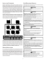
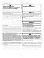
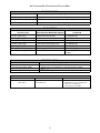
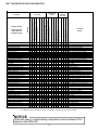
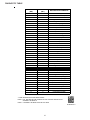
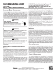
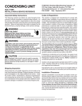
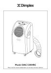
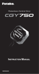
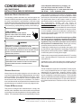
CONDENSING UNIT AIR CONDITIONING INSTALLATION & SERVICE REFERENCE IMPORTANT SAFETY INSTRUCTIONS The following symbols and labels are used throughout this manual to indicate immediate or potential safety hazards. It is the owner’s and installer’s responsibility to read and comply with all safety information and instructions accompanying these symbols. Failure to heed safety information increases the risk of personal injury, property damage, and/or product damage. WARNING HIGH VOLTAGE ! DISCONNECT ALL POWER BEFORE SERVICING . MULTIPLE POWER SOURCES MAY BE PRESENT . FAILURE TO DOS SO MAY CAUSE PROPERTY DAMAGE, PERSONAL INJURY OR DEATH . WARNING ONLY INDIVIDUALS MEETING THE REQUIREMENTS OF AN “ENTRY L EVEL TECHNICIAN”, AT A MINIMUM , AS SPECIFIED BY THE AIR CONDITIONING , HEATING AND REFRIGERATION INSTITUTE (AHRI) MAY USE THIS INFORMATION . ATTEMPTING TO INSTALL OR REPAIR THIS UNIT WITHOUT SUCH BACKGROUND MAY RESULT IN PRODUCT DAMAGE , PERSONAL INJURY, OR DEATH . © 2014 Goodman Manufacturing Company, L.P. 5151 San Felipe, Suite 500, Houston, TX 77056 www.goodmanmfg.com -or- www.amana-hac.com P/N: IO-449 Date: September 2014 ment installed in violation of any codes or regulations. Rated performance is achieved after 72 hours of operation. Rated performance is delivered at the specified airflow. See outdoor unit specification sheet for split system models or product specification sheet for packaged and light commercial models. Specification sheets can be found at www.goodmanmfg.com for Goodman® brand products or www.amana-hac.com for Amana® brand products. Within either website, please select the residential or commercial products menu and then select the submenu for the type of product to be installed, such as air conditioners or heat pumps, to access a list of product pages that each contain links to that model’s specification sheet. The United States Environmental Protection Agency (EPA) has issued various regulations regarding the introduction and disposal of refrigerants. Failure to follow these regulations may harm the environment and can lead to the imposition of substantial fines. Should you have any questions please contact the local office of the EPA. If replacing a condensing unit or air handler, the system must be manufacturer approved and Air Conditioning, Heating and Refrigeration Institute (AHRI) matched. NOTE: Installation of unmatched systems is strongly discouraged. Outdoor units are approved for operation above 55°F in cooling mode. Operation below 55°F requires the use of an approved low ambient kit. CAUTION SCROLL EQUIPPED UNITS SHOULD NEVER BE USED TO EVACUATE THE AIR CONDITIONING SYSTEM . VACUUMS THIS LOW CAN CAUSE INTERNAL ELECTRICAL ARCING RESULTING IN A DAMAGED OR FAILED COMPRESSOR. Operating the unit in a structure that is not complete (either as part of new construction or renovation) will void the warranty. FEATURES SHIPPING INSPECTION Always keep the unit upright; laying the unit on its side or top may cause equipment damage. Shipping damage, and subsequent investigation is the responsibility of the carrier. Verify the model number, specifications, electrical characteristics, and accessories are correct prior to installation. The distributor or manufacturer will not accept claims from dealers for transportation damage or installation of incorrectly shipped units. This air conditioner is a part of the ComfortNet™ family of products. It may be installed as part of a “legacy” system using a standard 24 VAC thermostat. However, with the CTK0* ComfortNet thermostat kit, this air conditioner may be installed as part of a digitally communicating system. The ComfortNet system provides automatic airflow configuration, enhanced setup features, and enhanced diagnostics. It also reduces the number of thermostat wires to a maximum of four and a minimum of two. CODES & REGULATIONS This product is designed and manufactured to comply with national codes. Installation in accordance with such codes and/ or prevailing local codes/regulations is the responsibility of the installer. The manufacturer assumes no responsibility for equip- is a registered trademark of Maytag Corporation or its related companies and is used under license to Goodman Company, L.P., Houston, TX. All rights reserved. INSTALLATION CLEARANCES SAFE REFRIGERANT HANDLING Special consideration must be given to location of the condensing unit(s) in regard to structures, obstructions, other units, and any/all other factors that may interfere with air circulation. Where possible, the top of the unit should be completely unobstructed; however, if vertical conditions require placement beneath an obstruction there should be a minimum of 60 inches between the top of the unit and the obstruction(s). The specified dimensions meet requirements for air circulation only. Consult all appropriate regulatory codes prior to determining final clearances. While these items will not cover every conceivable situation, they should serve as a useful guide. WARNING TO AVOID POSSIBLE INJURY, EXPLOSION OR DEATH, PRACTICE SAFE HANDLING OF REFRIGERANTS . WARNING REFRIGERANTS ARE HEAVIER THAN AIR. THEY CAN “PUSH OUT” THE OXYGEN IN YOUR LUNGS OR IN ANY ENCLOSED SPACE . TO AVOID POSSIBLE DIFFICULTY IN BREATHING OR DEATH : • NEVER PURGE REFRIGERANT INTO AN ENCLOSED ROOM OR SPACE. BY LAW , ALL REFRIGERANTS MUST BE RECLAIMED . • IF AN INDOOR LEAK IS SUSPECTED , THOROUGHLY VENTILATE THE AREA BEFORE BEGINNING WORK . • LIQUID REFRIGERANT CAN BE VERY COLD. TO AVOID POSSIBLE FROST BITE OR BLINDNESS, AVOID CONTACT AND WEAR GLOVES AND GOGGLES. IF LIQUID REFRIGERANT DOES CONTACT YOUR SKIN OR EYES, SEEK MEDICAL HELP IMMEDIATELY. • ALWAYS FOLLOW EPA REGULATIONS. NEVER BURN REFRIGERANT , AS POISONOUS GAS WILL BE PRODUCED . Another important consideration in selecting a location for the unit(s) is the angle to obstructions. Either side adjacent the valves can be placed toward the structure provided the side away from the structure maintains minimum service clearance. Corner installations are strongly discouraged. NOT RECOMMENDED B B B A OK! B AA WARNING AA C AA OK! TO AVOID POSSIBLE EXPLOSION, USE ONLY RETURNABLE (NOT DISPOSABLE) SERVICE CYLINDERS WHEN REMOVING REFRIGERANT FROM A SYSTEM . • ENSURE THE CYLINDER IS FREE OF DAMAGE WHICH COULD LEAD TO A LEAK OR EXPLOSION . • ENSURE THE HYDROSTATIC TEST DATE DOES NOT EXCEED 5 YEARS. • ENSURE THE PRESSURE RATING MEETS OR EXCEEDS 400 PSIG. WHEN IN DOUBT , DO NOT USE CYLINDER. OK! C AA AA OK! OK! OK! A AA C AA C Minimum Airflow Clearance Model Type A B C Residential 10" 10" 18" Light Commercial 12" 12" 18" AA 20" 24" WARNING TO AVOID POSSIBLE EXPLOSION: • NEVER APPLY FLAME OR STEAM TO A REFRIGERANT CYLINDER. IF YOU MUST HEAT A CYLINDER FOR FASTER CHARGING, PARTIALLY IMMERSE IT IN WARM WATER . • NEVER FILL A CYLINDER MORE THAN 80% FULL OF LIQUID REFRIGERANT . • NEVER ADD ANYTHING OTHER THAN R-22 TO AN R-22 CYLINDER OR R410A TO AN R-410A CYLINDER. THE SERVICE EQUIPMENT USED MUST BE LISTED OR CERTIFIED FOR THE TYPE OF REFRIGERANT USED . • STORE CYLINDERS IN A COOL, DRY PLACE. NEVER USE A CYLINDER AS A PLATFORM OR A ROLLER. This unit can be located at ground floor level or on flat roofs. At ground floor level, the unit must be on a solid, level foundation that will not shift or settle. To reduce the possibility of sound transmission, the foundation slab should not be in contact with or be an integral part of the building foundation. Ensure the foundation is sufficient to support the unit. A concrete slab raised above ground level provides a suitable base. ROOFTOP INSTALLATIONS If it is necessary to install this unit on a roof structure, ensure the roof structure can support the weight and that proper consideration is given to the weather-tight integrity of the roof. Since the unit can vibrate during operation, sound vibration transmission should be considered when installing the unit. Vibration absorbing pads or springs can be installed between the condensing unit legs or frame and the roof mounting assembly to reduce noise vibration. REFRIGERANT LINES CAUTION THE COMPRESSOR POE OIL FOR R-410A UNITS IS EXTREMELY SUSCEPTIBLE TO MOISTURE ABSORPTION AND COULD CAUSE COMPRESSOR FAILURE. DO NOT LEAVE SYSTEM OPEN TO ATMOSPHERE ANY LONGER THAN NECESSARY FOR INSTALLATION. 2 Use only refrigerant grade (dehydrated and sealed) copper tubing to connect the condensing unit with the indoor evaporator. After cutting the tubing, install plugs to keep refrigerant tubing clean and dry prior to and during installation. Tubing should always be cut square keeping ends round and free from burrs. Clean the tubing to prevent contamination. Do NOT let refrigerant lines come in direct contact with plumbing, ductwork, floor joists, wall studs, floors, and walls. When running refrigerant lines through a foundation or wall, openings should allow for sound and vibration absorbing material to be placed or installed between tubing and foundation. Any gap between foundation or wall and refrigerant lines should be filled with a pliable silicon-based caulk, RTV or a vibration damping material. Avoid suspending refrigerant tubing from joists and studs with rigid wire or straps that would come in contact with the tubing. Use an insulated or suspension type hanger. Keep both lines separate and always insulate the suction line. These sizes are suitable for line lengths of 79 feet or less. If a run of more than fifty feet is required, refer to Remote Cooling Service Manual, or TP-106 Long Line Set Application R-22, or TP-107 Long Line Set Application R-410A or contact your distributor for assistance. Insulation is necessary to prevent condensation from forming and dropping from the suction line. Armflex (or satisfactory equivalent) with 3/8” min. wall thickness is recommended. In severe conditions (hot, high humidity areas) 1/2” insulation may be required. Insulation must be installed in a manner which protects tubing from damage and contamination. BURYING REFRIGERANT LINES If burying refrigerant lines can not be avoided, use the following checklist. 1. Insulate liquid and suction lines separately. 2. Enclose all underground portions of the refrigerant lines in waterproof material (conduit or pipe) sealing the ends where tubing enters/exits the enclosure. 3. If the lines must pass under or through a concrete slab, ensure lines are adequately protected and sealed. Where possible, drain as much residual compressor oil from existing systems, lines, and traps; pay close attention to low areas where oil may collect. NOTE: If changing refrigerant types, ensure the indoor coil and metering device is compatible with the type of refrigerant being used; otherwise, the indoor coil must be replaced. REFRIGERANT LINE CONNECTIONS RECOMMENDED INTERCONNECTING TUBING (Ft) Cond Unit Tons Suct Liq Suct Liq Suct Liq 1 1/2 2 2 1/2 3 3 1/2 4 5 5/8 5/8 5/8 3/4 7/8 7/8 7/8 1/4 1/4 1/4 3/8 3/8 3/8 3/8 3/4 3/4 3/4 7/8 1 1/8 1 1/8 1 1/8 3/8 3/8 3/8 3/8 3/8 3/8 3/8 3/4 3/4 7/8 1 1/8 1 1/8 1 1/8 1 1/8 3/8 3/8 3/8 3/8 3/8 3/8 3/8 0-24 25-49 Line Diameter (In. OD) IMPORTANT 50-79* To avoid overheating the service valve, TXV valve, or filter drier while brazing, wrap the component with a wet rag, or use a thermal heat trap compound. Be sure to follow the manufacturer’s instruction when using the heat trap compound. Note: Remove Schrader valves from service valves before brazing tubes to the valves. Use a brazing alloy of 2% minimum silver content. Do not use flux. * Lines greater than 79 feet in length or vertical elevation changes more than 50 f eet refer to the Remote Cooling Service Manual or contact your distributor for assistance. 3 Pressure test the system using dry nitrogen and soapy water to locate leaks. If you wish to use a leak detector, charge the system to 10 psi using the appropriate refrigerant then use nitrogen to finish charging the system to working pressure then apply the detector to suspect areas. If leaks are found, repair them. After repair, repeat the pressure test. If no leaks exist, proceed to system evacuation. Torch heat required to braze tubes of various sizes is proportional to the size of the tube. Tubes of smaller size require less heat to bring the tube to brazing temperature before adding brazing alloy. Applying too much heat to any tube can melt the tube. Service personnel must use the appropriate heat level for the size of the tube being brazed. NOTE: The use of a heat shield when brazing is recommended to avoid burning the serial plate or the finish on the unit. SYSTEM EVACUATION Condensing unit liquid and suction valves are closed to contain the charge within the unit. The unit is shipped with the valve stems closed and caps installed. Do not open valves until the system is evacuated. 1. The ends of the refrigerant lines must be cut square, deburred, cleaned, and be round and free from nicks or dents. Any other condition increases the chance of a refrigerant leak. 2. “Sweep” the refrigerant line with nitrogen or inert gas during brazing to prevent the formation of copper-oxide inside the refrigerant lines. The POE oils used in R410A applications will clean any copper-oxide present from the inside of the refrigerant lines and spread it throughout the system. This may cause a blockage or failure of the metering device. 3. After brazing, quench the joints with water or a wet cloth to prevent overheating of the service valve. 4. Ensure the filter drier paint finish is intact after brazing. If the paint of the steel filter drier has been burned or chipped, repaint or treat with a rust preventative. This is especially important on suction line filter driers which are continually wet when the unit is operating. WARNING REFRIGERANT UNDER PRESSURE! FAILURE TO FOLLOW PROPER PROCEDURES MAY CAUSE PROPERTY DAMAGE , PERSONAL INJURY OR DEATH. NOTE: Scroll compressors should never be used to evacuate or pump down a heat pump or air conditioning system. CAUTION PROLONGED OPERATION AT SUCTION PRESSURES LESS THAN 20 PSIG FOR MORE THAN 5 SECONDS WILL RESULT IN OVERHEATING OF THE SCROLLS AND PERMANENT DAMAGE TO THE SCROLL TIPS , DRIVE BEARINGS AND INTERNAL SEAL . NOTE: Be careful not to kink or dent refrigerant lines. Kinked or dented lines will cause poor performance or compressor damage. 1. Connect the vacuum pump with 250 micron capability to the service valves. 2. Evacuate the system to 250 microns or less using suction and liquid service valves. Using both valves is necessary as some compressors create a mechanical seal separating the sides of the system. 3. Close pump valve and hold vacuum for 10 minutes. Typically pressure will rise during this period. • If the pressure rises to 1000 microns or less and remains steady the system is considered leak-free; proceed to startup. • If pressure rises above 1000 microns but holds steady below 2000 microns, moisture and/or noncondensibles may be present or the system may have a small leak. Return to step 2: If the same result is encountered check for leaks as previously indicated and repair as necessary then repeat evacuation. Do NOT make final refrigerant line connection until plugs are removed from refrigerant tubing. NOTE: Before brazing, verify indoor piston size by checking the piston kit chart packaged with indoor unit. LEAK TESTING (NITROGEN OR NITROGEN-TRACED) WARNING TO AVOID THE RISK OF FIRE OR EXPLOSION, NEVER USE OXYGEN , HIGH PRESSURE AIR OR FLAMMABLE GASES FOR LEAK TESTING OF A REFRIGERATION SYSTEM . WARNING • TO AVOID POSSIBLE EXPLOSION, THE LINE FROM THE NITROGEN CYLINDER MUST INCLUDE A PRESSURE REGULATOR AND A PRESSURE RELIEF VALVE . THE PRESSURE RELIEF VALVE MUST BE SET TO OPEN AT NO MORE THAN 150 PSIG. 4 If pressure rises above 2000 microns, a leak is present. Check for leaks as previously indicated and repair as necessary then repeat evacuation. These devices have sufficient time delay to permit the motorcompressor to start and accelerate its load. 5000 VACUUM IN MICRONS 4500 HIGH VOLTAGE CONNECTIONS 4000 Route power supply and ground wires through the high voltage port and terminate in accordance with the wiring diagram provided inside the control panel cover. LEAK(S) PRESENT 3500 3000 2500 LOW VOLTAGE CONNECTIONS 2000 CONDENSIBLES OR SMALL LEAK PRESENT 1500 Condensing unit control wiring requires a nominal 24 VAC (+/6 VAC), 60 Hz, minimum 25 VA service from either the indoor or optional outdoor transformer. Low voltage wiring for the condensing units depends on the thermostat used. The unit is designed to work as part of a fully communicating HVAC system utilizing the ComfortNet™, CTK0* thermostat, ComfortNet compatible indoor unit, and up to four wires. The unit also has legacy 24 VAC inputs to support non-communicating systems. Route control wires through the low voltage port and terminate in accordance with the wiring diagram provided inside the control panel cover. 1000 NO LEAKS NO CONDENSIBLES 500 0 1 2 3 4 5 6 MINUTES 7 8 9 10 ELECTRICAL CONNECTIONS WARNING HIGH VOLTAGE! DISCONNECT ALL POWER BEFORE SERVICING . MULTIPLE POWER SOURCES MAY BE PRESENT . FAILURE TO DO SO MAY CAUSE PROPERTY DAMAGE , PERSONAL INJURY OR DEATH DUE TO ELECTRIC SHOCK . WIRING MUST CONFORM WITH NEC OR CEC AND ALL LOCAL CODES . UNDERSIZED WIRES COULD CAUSE POOR EQUIPMENT PERFORMANCE, EQUIPMENT DAMAGE OR FIRE. HIGH VOLTAGE PORT WARNING TO AVOID THE RISK OF FIRE OR EQUIPMENT DAMAGE , USE COPPER CONDUCTORS. LOW VOLTAGE PORT Voltage Ports NOTICE NOTE: If the condensing unit is wired in the communicating mode together with the compatible communicating indoor unit and thermostat, then the communicating thermostat is able to search and identify the condensing unit when power is applied to the system. Refer to the Installation Manual of the communicating thermostat for more information. UNITS WITH RECIPROCATING COMPRESSORS AND NON-BLEED TXV’S REQUIRE A H ARD START KIT. The condensing unit rating plate lists pertinent electrical data necessary for proper electrical service and overcurrent protection. Wires should be sized to limit voltage drop to 2% (max.) from the main breaker or fuse panel to the condensing unit. Consult the NEC, CEC, and all local codes to determine the correct wire gauge and length. Local codes often require a disconnect switch located near the unit; do not install the switch on the unit. Refer to the installation instructions supplied with the indoor furnace/air handler for specific wiring connections and indoor unit configuration. Likewise, consult the instructions packaged with the thermostat for mounting and location information. Y2 Thermostat Two-Stage Heating with Two-Stage Cooling Y2 FURNACE OR AIR HANDLER Y2 OVERCURRENT PROTECTION OD UNIT Two-Stage Non-Communicating Thermostat Low Voltage Wire Connection (legacy mode) The following overcurrent protection devices are approved for use. • Time delay fuses • HACR type circuit breakers 5 SYSTEM START UP CHARGE VERIFICATION WARNING CAUTION POSSIBLE REFRIGERANT LEAK! REFRIGERANT UNDER PRESSURE! TO AVOID A POSSIBLE REFRIGERANT LEAK, OPEN THE SERVICE VALVES UNTIL THE TOP OF THE STEM IS 1/8” FROM THE RETAINER . • DO NOT OVERCHARGE SYSTEM WITH REFRIGERANT . • DO NOT OPERATE UNIT IN A VACUUM OR AT NEGATIVE PRESSURE. FAILURE TO FOLLOW PROPER PROCEDURES MAY CAUSE PROPERTY DAMAGE , PERSONAL INJURY OR DEATH. NOTE: Power must be supplied to the 18 SEER outdoor units containing ECM motors before the power is applied to the indoor unit. Sending a low voltage signal without high voltage power present at the outdoor unit can cause malfunction of the control module on the ECM motor. CAUTION USE REFRIGERANT CERTIFIED TO AHRI STANDARDS. USED REFRIGERANT MAY CAUSE COMPRESSOR DAMAGE , AND IS NOT COVERED UNDER THE WARRANTY . MOST PORTABLE MACHINES CANNOT CLEAN USED REFRIGERANT TO MEET AHRI STANDARDS . Adequate refrigerant charge for the matching HSVTC evaporator coil and 15 feet of lineset is supplied with the condensing unit. If using evaporator coils other than HSVTC coil it maybe necessary to add or remove refrigerant to attain proper charge. If line set exceeds 15 feet in length, refrigerant should be added at .6 ounces per foot of liquid line. NOTICE VIOLATION OF EPA REGULATIONS MAY RESULT IN FINES OR OTHER PENALTIES. NOTE: Charge should always be checked using superheat when using a piston and subcooling when using TXV equipped indoor coil to verify proper charge. CAUTION Open the suction service valve first! If the liquid service valve is opened first, oil from the compressor may be drawn into the indoor coil TXV, restricting refrigerant flow and affecting operation of the system. OPERATING THE COMPRESSOR WITH THE SUCTION VALVE CLOSED MAY CAUSE SERIOUS COMPRESSOR DAMAGE . FINAL CHARGE ADJUSTMENT When opening valves with retainers, open each valve only until the top of the stem is 1/8” from the retainer. To avoid loss of refrigerant, DO NOT apply pressure to the retainer. When opening valves without a retainer remove service valve cap and insert a hex wrench into the valve stem and back out the stem by turning the hex wrench counterclockwise. Open the valve until it contacts the rolled lip of the valve body. The outdoor temperature must be 60°F or higher. Set the room thermostat to COOL, fan switch to AUTO, and set the temperature control well below room temperature. After system has stabilized per startup instructions, check subcooling and superheat as detailed in the following section. NOTE: These are not back-seating valves. It is not necessary to force the stem tightly against the rolled lip. CAUTION TO PREVENT PERSONAL INJURY, CAREFULLY CONNECT AND DISCONNECT MANIFOLD GAUGE HOSES . ESCAPING LIQUID REFRIGERANT CAN CAUSE BURNS. DO NOT VENT REFRIGERANT INTO THE ATMOSPHERE. RECOVER After the refrigerant charge has bled into the system, open the liquid service valve. The service valve cap is the secondary seal for the valves and must be properly tightened to prevent leaks. Make sure cap is clean and apply refrigerant oil to threads and sealing surface on inside of cap. Tighten cap finger-tight and then tighten additional 1/6 of a turn (1 wrench flat) to properly seat the sealing surfaces. EXPANSION VALVE SYSTEM Do not introduce liquid refrigerant from the cylinder into the crankcase of the compressor as this may damage the compressor. NOTE: Units matched with indoor coils equipped with non-adjustable TXV should be charged by subcooling only. 1. Break vacuum by fully opening liquid and suction base valves. 2. Set thermostat to call for cooling. Check indoor and outdoor fan operation and allow system to stabilize for 10 minutes for fixed orifices and 20 minutes for expansion valves. Run the remote on low stage cooling for 10 minutes until refrigerant pressures stabilize. Use the following guidelines and methods to check unit operation and ensure that the refrigerant charge is within limits. Charge the unit on low stage. 1. Purge gauge lines. Connect service gauge manifold to base-valve service ports. ALL REFRIGERANT DURING SYSTEM REPAIR AND BEFORE FINAL UNIT DISPOSAL. 6 2. Temporarily install a thermometer on the liquid line at the liquid line service valve and 4-6" from the compressor on the suction line. Ensure the thermometer makes adequate contact and is insulated for best possible readings. Use liquid line temperature to determine subcooling and vapor temperature to determine superheat. b. If subcooling and superheat are high, adjust TXV valve to 7 to 9 ºF superheat, then check subcooling. d. If subcooling is high and superheat is low, adjust TXV valve to 7 to 9 ºF superheat and remove charge to lower the subcooling to 5 to 7 ºF. NOTE: Do NOT adjust the charge based on suction pressure unless there is a gross undercharge. 4. Disconnect manifold set, installation is complete. 3. Check subcooling and superheat. Systems with TXV application should have a subcooling of 5 to 7ºF and superheat of 7 to 9 ºF. a. c. If subcooling and superheat are low, adjust TXV to 7 to 9 ºF superheat, then check subcooling. NOTE: Check the Schrader ports for leaks and tighten valve cores if necessary. Install caps finger-tight. NOTE: To adjust superheat, turn the valve stem clockwise to increase and counter clockwise to decrease. SUPERHEAT FORMULA = SUCT. LINE TEMP. - SAT. SUCT. TEMP. If subcooling is low and superheat is high, add charge to raise subcooling to 5 to 7 ºF then check superheat. SATURATED SUCTION PRESSURE TEMPERATURE CHART SUCTION PRESSURE PSIG SATURATED LIQUID PRESSU RE TEMPERATURE CHART SATURATED SUCTION TEMPERATURE ºF R-22 LIQUID PRESSURE R-410A SATURATED LIQUID TEMPERATURE ºF PSIG R-22 200 101 70 210 105 73 6 220 225 108 110 76 78 32 7 235 113 80 34 8 245 116 83 62 35 10 64 37 11 255 265 119 121 85 88 66 38 13 275 124 90 68 40 14 285 127 92 70 41 15 72 42 16 295 305 130 133 95 97 74 44 17 325 137 101 76 45 19 355 144 108 78 46 20 375 148 112 80 48 21 405 155 118 85 50 24 415 157 119 90 53 26 425 n/a 121 95 56 29 100 59 31 435 445 n/a n/a 123 125 110 64 36 475 n/a 130 120 69 41 500 n/a 134 130 73 45 140 78 49 525 550 n/a n/a 138 142 150 83 53 575 n/a 145 160 86 56 170 90 60 600 625 n/a n/a 149 152 50 26 1 52 28 3 54 29 4 56 31 58 60 7 R-410A On the other hand, the indoor unit, outdoor unit, and thermostat comprising a ComfortNet system “communicate” digitally with one another. It is now a two-way communications path. The thermostat still sends commands to the indoor and outdoor units. However, the thermostat may also request and receive information from both the indoor and outdoor units. This information may be displayed on the CT thermostat. The indoor and outdoor units also interact with one another. The outdoor unit may send commands to or request information from the indoor unit. This two-way digital communications between the thermostat and subsystems (indoor/outdoor unit) and between subsystems is the key to unlocking the benefits and features of the ComfortNet system. ADDITIONAL NOTES: 1. There are (3) 7-segment LED displays on the PCB. See the Troubleshooting Tables at the end of this manual for definitions of the LED status. 2. When system is at Standby mode, press “TEST” push button to turn on both compressor and outdoor fan for five (5) seconds. 3. Press “RECALL” push-button to retrieve the six most recent faults. The control must be in Standby Mode (no thermostat inputs) to use the feature. Depress the pushbutton for approximately two seconds and less than five seconds. The (3) 7-segment LED displays will then display the six most recent faults beginning with the most recent fault and decrementing to the least recent fault. The faults may be cleared by depressing the button for greater than five seconds. Consecutively repeated faults are displayed a maximum of three times. Refer to the fault code definitions at the end of this manual for more details. 4. “TERM” dipswitch is used for communications bus configuration. Leave the settings to the factory default position. 5. “LEARN” push button is used in communication mode to support device recognition on start-up. As the communication system supports automatic identification of both indoor unit and outdoor unit, this button is not used for a normal start-up. Two-way digital communications is accomplished using only two wires. The thermostat and subsystem controls are powered with 24 VAC Thus, a maximum of 4 wires between the equipment and thermostat is all that is required to operate the system. AIRFLOW CONSIDERATIONS Airflow demands are managed differently in a fully communicating system than they are in a legacy wired system. The system operating mode (as determined by the thermostat) determines which unit calculates the system airflow demand. If the indoor unit is responsible for determining the airflow demand, it calculates the demand and sends it to the ECM motor. If the outdoor unit or thermostat is responsible for determining the demand, it calculates the demand and transmits the demand along with a fan request to the indoor unit. The indoor unit then sends the demand to the ECM motor. The following table lists the various ComfortNet™ systems, the operating mode, and airflow demand source. COMFORTNET™ SYSTEM OVERVIEW The ComfortNet system (or CT system) is a system that includes a ComfortNet compatible air handler/furnace/modular blower and air conditioner or heat pump with a CTK0* thermostat. Any other system configurations are considered invalid ComfortNet systems and must be connected as a tradition (or legacy) system. The table below compares the valid CT systems. CT compatib le Air Handler/Furnace/Modular Blower CT compatib le Air Handler/Furnace/Modular Blower CT compatib le Air Conditioner Full CT system b enefits & features CT compatible Heat Pump Full CT system b enefits & features Sys te m A ir Conditioner + A ir Handler A ir Conditioner + Furnace A ComfortNet heating/air conditioning system differs from a legacy/traditional system in the manner in which the indoor unit, outdoor unit and thermostat interact with one another. In a traditional system, the thermostat sends commands to the indoor and outdoor units via analog 24 VAC signals. It is a one-way communication path in that the indoor and outdoor units typically do not return information to the thermostat. 8 Sys te m Ope r ating M ode Air flow De m and Sour ce Cooling A ir Conditioner Heating A ir Handler Continuous Fan Thermostat Cooling A ir Conditioner Heating Furnace Continuous Fan Thermostat For example, assume the system is an air conditioner matched with an air handler. With a call for low stage cooling, the air conditioner will calculate the system’s low stage cooling airflow demand. The air conditioner will then send a fan request along with the low stage cooling airflow demand to the air handler. Once received, the air handler will send the low stage cooling airflow demand to the ECM motor. The ECM motor then delivers the low stage cooling airflow. The table below lists the nominal high and low stage airflow for the ComfortNet air conditioners. M ode l Hig h TWO-WIRE OUTDOOR, FOUR-WIRE INDOOR WIRING Two wires only may be utilized between the indoor and outdoor units. For this wiring scheme, only the data lines, 1 and 2, are required between the indoor and outdoor units. A 40 VA, 208/ 230 VAC to 24 VAC transformer must be installed in the outdoor unit to provide 24 VAC power to the outdoor unit’s electronic control. The CTK0* manual will state if this transformer is optional or mandatory. See kit instructions for mounting and wiring instructions. Four wires are required between the indoor unit and thermostat. NOTE: Use of the CTK0* transformer is recommended if installing a dual fuel system. Failure to use the transformer in the outdoor unit could result in over loading of the furnace transformer. L ow *SXC160241 800 600 *SXC160361 1200 800 *SXC160481 1550 1100 *SXC160601 1800 1400 *SXC180361 1250 850 *SXC180481 1750 1210 *SXC180601 1750 1210 CTK0* WIRING 40VA Transformer NOTE: Refer to Electrical Connections - High Voltage Connections for 208/230 volt line connections to the air conditioner. 208/230 VAC 1 2 R C CT Compatible Air Handler/Furnace/Modular Blower Integrated Control Module 1 2 R C 2 CT Compatible Air Handler/Furnace/Modular R C Blower Integrated Control Module 1 2 R C CT Compatible AC/HP Integrated Control Module 24 VAC CONFIGURATION The configuration menu provides functional information about the installed equipment. System tonnage and number of cooling and heating stages are displayed within this menu. A tonnage check will help determine if the equipment shared data is correct for the unit. If the tonnage is not correct, even though very rare, a memory card is available to load the proper data. Typical wiring will consist of four wires between the indoor unit and outdoor unit and between the indoor unit and thermostat. The required wires are: (a) data lines, 1 and 2; (b) thermostat “R” (24 VAC hot) and “C” (24 VAC common). R C 1 The ComfortNet system permits access to additional system information, advanced setup features, and advanced diagnostic/troubleshooting features. These advanced features are organized into a menu structure. See thermostat installation manual for directions on how to access the ComfortNet User Menus. See following tables for menu layout. FOUR-WIRE INDOOR AND OUTDOOR WIRING 2 R C COMFORTNET™ SYSTEM ADVANCED FEATURES Typical 18 AWG thermostat wire may be used to wire the system components. However, communications reliability may be improved by using a high quality, shielded, twisted pair cable for the data transmission lines. In either case, 125 feet is the maximum length of wire between indoor unit and outdoor unit, or between indoor unit and thermostat. 1 2 System Wiring using Two-Wires between the indoor unit and AC/HP and Four-Wires between the indoor unit and Thermostat NOTE: A removable plug connector is provided with the control to make thermostat wire connections. This plug may be removed, wire connections made to the plug, and replaced. It is strongly recommended that multiple wires into a single terminal be twisted together prior to inserting into the plug connector. Failure to do so may result in intermittent operation. CTK0* Thermostat CTK0* Thermostat 1 DIAGNOSTICS Accessing the air conditioner/heat pump’s diagnostics menu provides ready access to the last six faults detected by the air conditioner/heat pump. Faults are stored most recent to least recent. Any consecutively repeated fault is stored a maximum of three times. Example: The power supply to the air conditioner/heat pump is continuously below 187 VAC. The control will only store this fault the first three consecutive times the fault occurs. CT Compatible AC/HP Integrated Control Module System Wiring Using Four-Wires NOTE: It is highly recommended that the fault history be cleared after performing maintenance or servicing the heat pump. 9 • IDENTIFICATION Model Number, Serial Number and Software Version are displayed within this menu. A model number check will help determine if the equipment shared data is correct for the unit. If the model number is not correct, even though very rare, a memory card is available to load the proper data. Profile D ramps up to 50% of the demand for 1/2 minute, then ramps to 82% of the full cooling demand airflow and operates there for approximately 7 1/2 minutes. The motor then steps up to the full demand airflow. Profile D has a 1/2 minute at 50% airflow OFF delay. OFF OFF SENSORS The outdoor ambient temperature and coil temperature are displayed in the Sensor Menu. This information can be used for troubleshooting purposes. Airflow Tables STATUS COOL SET-UP The current system operational mode and requested indoor CFM is reported in this menu. This information can be used for troubleshooting purposes. This menu allows for the adjustment of several cooling performance variables. Cool Airflow Trim (range from -10% to 10% in 2% increments), Cool Airflow Profiles, Cool Fan ON Delay, Cool Fan OFF Delay and Dehumidification Select (enable or disable dehumidification) can be adjusted in this menu. See the following images showing the four cooling airflow profiles. • Profile A (default) provides only an OFF delay of one (1) minute at 100% of the cooling demand airflow. 100% CFM 100% CFM OFF OFF 1 min • Profile B ramps up to full cooling demand airflow by first stepping up to 50% of the full demand for 30 seconds. The motor then ramps to 100% of the required airflow. A one (1) minute OFF delay at 100% of the cooling airflow. 100% CFM 100% CFM 50% CFM OFF OFF 1/2 min • OFF 1 min Profile C ramps up to 82% of the full cooling demand airflow and operates there for approximately 7 1/2 minutes. The motor then steps up to the full demand airflow. Profile C also has a one (1) minute 100% OFF delay. 100% CFM OFF 10 AIR CONDITIONER/HEAT PUMP ADVANCED FEATURES MENU CONFIGURATION Subme nu Ite m Number of AC Stages (CL STG) Indica tion (for Displa y Only; not Use r M odifia ble ) Number of HP Stages (HT STG) Displays the num ber of air conditioning stages ; applies to AC and HP Displays the num ber of heat pump stages; applies to HP only . AC Tonnage (TONS) Displays the air c onditioning tonnage; applies to AC and HP. DIAGNOSTICS Submenu Item Indication/User Modifiable Options Comments Fault 1 (FAULT #1) Most recent AC/HP fault For display only Fault 2 (FAULT #2) Next most recent AC/HP fault For display only Fault 3 (FAULT #3) Next most recent AC/HP fault For display only Fault 4 (FAULT #4) Next most recent AC/HP fault For display only Fault 5 (FAULT #5) Next most recent AC/HP fault For display only Fault 6 (FAULT #6) Clear Fault History (CLEAR) Least recent AC/HP fault NO or YES For display only Selecting "YES" clears the fault history NOTE: Consecutively repeated faults are shown a maximum of three (3) times. ID ENTIFIC ATION Subm e nu Ite m Indica tion (for Displa y Only; not Use r M odifia ble ) Model Num ber (M OD NUM) Display s the air conditioner or heat pump model number Serial Number (SER NUM) Display s the air conditioner or heat pump serial num ber (O ti sl)the application software revision Display Software (SOFTW ARE) S ENS O R S S u b m e n u Ite m O utdoo r A ir Tem p erat ure (A IR TM P ) U se r M o d ifia b le O p tio n s D is p lay s the outdo or a ir t em p erat ure 11 C o m m e n ts S e ns or m a y or m ay not be ava ila ble o n an air c ondit ioner. Ch ec k air c o nditio ner in s tru c tion s for deta ils . COOL SET-UP Submenu Item Cool Airflow Trim (CL TRM) Cool Airflow Profile (CL PRFL) Cool ON Delay (CL ON) Cool OFF Delay (CL OFF) Dehumidification Select (DEHUM) User Modifiable Options -10% to +10% in 2% increments, default is 0% A, B, C, or D, default is A 5, 10, 20, or 30 seconds, default is 5 seconds 30, 60, 90, or 120 seconds, default is 30 seconds ON or OFF (default is OFF) Comments Selects the airflow trim amount; applies to air conditioner only. Selects the airflow profile; applies to air conditioner only. Selects the indoor blower ON delay; applies to air conditioner only. Selects the indoor blower OFF delay; applies to air conditioner only. Selecting "OFF" disables dehumidification; selecting "ON" enables dehumidification; applies to air conditioner only. S T AT US S u bm e n u Ite m M ode (M O DE ) Ind ica tio n (fo r Disp la y O nly; n ot Use r M o d ifia ble ) Dis play s the c urrent air c onditioner or heat pum p operating m ode CF M (CFM ) Dis play s the airflow for the c urrent operating m ode 12 NETWORK TROUBLESHOOTING Verify that the bus TERM dipswitches are in the ON position. OFF ON 1 TERM 2 TERM The ComfortNet™ system is a fully communicating system which operates over a communicating network. Occasionally the need to troubleshoot the network may arise. The integrated control module has some on-board tools that may be used to troubleshoot the network. These tools are: red communications LED, green receive (Rx) LED, and learn button. • Red communications LED - Indicates the status of the network. The table below indicates the LED status and the corresponding potential problem. • Green receive LED - Indicates network traffic. The table below indicates the LED status and the corresponding potential problem. • LEARN button - Used to reset the network. Depress the button for approximately 2 seconds to reset the network. SYSTEM TROUBLESHOOTING NOTE: Refer to the instructions accompanying the CT compatible indoor air handler/furnace/modular blower unit for troubleshooting information. Refer to the Troubleshooting Chart at the end of this manual for a listing of possible air conditioner and heat pump error codes, possible causes and corrective actions. 13 LED LED Status Off 1 Flash Indication • Normal condition • Communic ations Failure Possible Causes • • None Communications Failure Corrective Action(s) • • None Depress LE ARN Button Red Communications LED Notes & Cautions • • • 2 Flashes • Out-of-box reset Off • No power • Communications error • • • Control power up Learn button depressed No power to furnace • None • • • Turn power OFF prior to repair • • Open fuse Communications error • • Chec k fuses and circuit breakers; replace/reset Replace blown fuse Chec k for shorts in low voltage wiring s ystem Reset network by depressing learn button Chec k data 1/ data 2 voltages Chec k communications wiring (data 1/ data 2 wires) Chec k wire connections at terminal block • • 1 S teady Flas h • No network found None Depress once quickly for a power-up reset Depress and hold for 2 seconds for an out-of-box res et None • Broken/ dis connected data wire(s) • • AC/HP is installed as a legacy/ traditional system • • Turn power OFF prior to repair • Verify wires at terminal block s are securely twisted together prior to inserting into terminal block Control is “talking” on network as expected Data 1 and data 2 wires reversed • Check communications at indoor unit, thermos tat, or wiring (data 1/ data 2 CT compatible outdoor unit wires) • None • Short between data 1 and data 2 wires • Check wire connections at terminal block • • Short between data 1 or data 2 wires and R (24 V AC) or C (24 VA C common) • Check data 1/ data 2 voltages • V erify installation type (legacy/ traditional or communicating) • Check data 1/ data 2 voltages • None Green Receive LED Rapid Flashing • Normal network traffic • On Solid • Data 1/ Data 2 miss-wire • 14 • Turn power OFF prior to repair Verify wires at terminal block s are securely twisted together prior to inserting into terminal block UNIT TROUBLESHOOTING INFORMATION Power Failure Blown Fuse Loose Connection Shorted or Broken Wires Open Overload Faulty Thermostat Faulty Transformer Shorted or Open Capacitor Internal Compressor Overload Open Shorted or Grounded Compressor Compressor Stuck Faulty Compressor Contactor Faulty Fan Relay Open Control Circuit Low Voltage Faulty Evaporator Fan Motor Shorted or Grounded Fan Motor Improper Cooling Anticipator Shortage or Refrigerant Restricted Liquid Line Undersized Liquid Line Undersized Suction Line Not Enough Air across Indoor Coil Too Much Air across Indoor Coil Overcharge of Refrigerant Noncondensibles Recirculation of Condensing Air Infiltration of Outdoor Air Improperly Located Thermostat Air Flow Unbalanced System Undersized Broken Internal Parts Broken Valves Inefficient Compressor High Pressure Control Open Unbalanced Power, 3PH Wrong Type Expansion Valve Expansion Valve Restricted Oversized Expansion Valve Undersized Expansion Valve Expansion Valve Bulb Loose Inoperative Expansion Valve Loose Hold-down Bolts • • • • • • • • • • • • • • • • • • • • • • • • • • • • • • • • • High head pressure High suction pressure Low head pressure Low suction pressure Compressor is noisy Certain areas to cool others to warm • • • • • • • • • • • • • • • • • • • • • • • • • • • • • • • • • • • • • • • • • • • Not cool enough on warm days Too cool and then too warm System runs continuously - little cooling • • • • Test Method Remedy • • • • • • Compressor cycles on overload Compressor runs - goes off on overload Condenser fan will not start Evaporator fan will not start Compressor and Condenser Fan will not start Compressor will not start - fan runs SYMPTOM DOTS IN ANALYSIS GUIDE INDICATE "POSSIBLE CAUSE" System will not start POSSIBLE CAUSE System Operating Pressures Unsatisfactory Cooling No Cooling Complaint • • • • • • • • • • • • • • • • • • • • • • • • • • Test Voltage Impact Fuse Size & Type Inspect Connection - Tighten Test Circuits with Ohmmeter Test Continuity of Overloads Test Continuity of Thermostat and Wiring Check Control Circuit with Voltmeter Test Capacitor Test Continuity of Overload Test Motor Windings Use Test Cord Test Continuity of Coil and Contacts Test Continuity of Coil and Contacts Test Control Circuit with Voltmeter Test Voltage Repair or Replace Test Motor Windings Check Resistance of Anticipator Test For Leaks, Add Refrigerant Replace Restricted Part Replace Line Replace Line Speed Blower, Check Duct Static Pressure Reduce Blower Speed Recover Part of Charge Recover Charge, Evacuate, Recharge Remove Obstruction to Air Flow Check Windows, Doors, Vent Fans, Etc. Relocate Thermostat Readjust Air Volume Dampers Refigure Cooling Load Replace Compressor Test Compressor Efficiency Test Compressor Efficiency Reset and Test Control Test Voltage Replace Valve Replace Valve Replace Valve Replace Valve Tighten Bulb Bracket Check Valve Operation Tighten Bolts For detailed service information refer to the Remote Condensing Unit Service manual. NOTICE Units with rotary or reciprocating compressors and non-bleed TXV’s require a Hard Start Kit. 15 DIAGNOSTIC TABLE 7 SEGMENT LED (DS2) 0 0 0 0 0 0 0 0 0 0 0 0 8 A A b b C C C d d d d d d d d E E F H L L L L L P P P P 7 SEGMENT LED (DS1) n 1 1 2 2 3 4 5 6 7 8 9 8 2 3 0 9 3 1 2 F t E 0 1 2 3 4 E 5 t 8 1 2 6 7 8 3 1 2 0 DESCRIPTION OF CONDITION Standby Low Pressure CO Trip Low Side Fault High Pressure CO Trip High Side Fault Short Cy cling Locked Rotor Open Circuit Open Start Circuit Open Run Circuit No Line Voltage Low Pilot Voltage Pow er Up Outdoor Air Temp Sensor Fault Outdoor Coil Temp Sensor Fault * No Indoor Airflow Inadequate Airflow Cool Mode Short Cycle Timer Low Cool High Cool Defrost * Max Defrost Time * Forced Defrost * Data not yet on Netw ork Invalid Data on Netw ork System Mis-Match Conf iguration Mis-Match Invalid Memory Card Data Board Misoperation Open Fuse Field Test Mode High Line Voltage LPCO Lockout (3 Trips) HPCO Lockout (3 Trips) Open Start Circuit Lockout Open Run Circuit Lockout Low Line Voltage Heat Mode Short Cycle Timer * Low Heat * High Heat * Comp Protector Open * CODE USED ON HEAT PUMP MODELS ONLY NOTE 1: DS1, DS2 AND DS3 ARE LABELED ON THE CONTROL ABOVE EACH 7 SEGMENT LED DISPLAY NOTE 2: 7 SEGMENT LED DISPLAY DS3 IS NOT USED 0140M00407-A 16 TROUBLESHOOTING INFORMATION: UNITARY DIAGNOSTIC CODES 3934%-42/5",%3(//4).' 5.)4!29$)!'./34)##/$%3 3YMPTOMSOF !BNORMAL/PERATION ,EGACY#OMFORT.ET 4HERMOSTAT $IAGNOSTIC3TATUS ,%$$ISPLAY#ODES $IGIT $IGIT $IGIT sIntegrated control module diagnostic/status LED display shows the indicated code. s#OMFORT.ETTHERMOSTAT displays ‘---‘ in the temperature display area. ",!.+ A 2 sHeat pump fails to operate in heating mode. sIntegrated control module diagnostic/status LED display shows the indicated code. s#OMFORT.ETTHERMOSTAT displays error message. ",!.+ A sAir conditioner/heat pump fails to operate. sIntegrated control module diagnostic/status LED display shows the indicated code. ",!.+ sAir conditioner/heat pump fails to operate. sIntegrated control module diagnostic/status LED display shows the indicated code. &AULT $ESCRIPTION #OMFORT.ET4- 4HERMOSTAT/NLY 0OSSIBLE #AUSES #ORRECTIVE !CTIONS .OTES #AUTIONS -ESSAGE #ODE sOutdoor air temp sensor fault AIR 3%.3/2 FLT A2 sShorted sensor. sOpen sensor. sSensor disconnected. sSensor out of range. sCheck sensor connection. sReplace open/ shorted sensor. sTurn power OFF prior to repair. sReplace with correct replacement part. 3 sOutdoor coil temp sensor fault COIL 3%.3/2 FLT A3 sShorted sensor sOpen sensor. sSensor. disconnected. sSensor out of range. sCheck sensor connection. sReplace open/ shorted sensor. sTurn power OFF prior to repair. sReplace with correct replacement part. E 5 sOpen fuse ",/7. FUSE E5 sShort in low voltage wiring. sLocate and correct short in low voltage wiring. sTurn power OFF prior to repair. sReplace fuse with 3-amp automotive type. ",!.+ E E sBoard misoperation ).4%2.!, FAULT EE sCompressor relay contacts welded. sReplace control. sTurn power OFF prior to repair sReplace with correct replacement part. sAir conditioner/heat pump fails to operate. sIntegrated control module diagnostic/status LED display shows the indicated code. s#OMFORT.ETTHERMOSTAT displays error message. ",!.+ b 0 sCirculator blower motor is not running when it should be running. MOTOR ./425. b0 sCheck indoor sTurn power OFF prior sIndoor blower blower motor. to repair. motor problem. sApplies only to fully sCommunications sCheck indoor blower motor communicating system error between indoor and wiring. USING#OMFORT.ET outdoor unit. sCheck indoor unit thermostat. control. sReplace with correct replacement part. sRepair/ replace any faulty wiring. sRepair/ replace indoor blower motor or control. s Air conditioner/heat pump operates at reduced performance. sAir conditioner/heat pump operating at low stage when expected to operate at high stage. sIntegrated control module diagnostic/status LED display shows the indicated code. ",!.+ b 9 sAirflow is lower than demanded LOW ID AIRFLOW b9 sIndoor blower motor problem s Blocked filters. sRestrictive/ undersized ductwork sIndoor/ outdoor unit miss-match. 17 sCheck indoor sTurn power OFF prior blower motor. to repair. sCheck filters; sApplies only to fully clean/replace as communicating system needed. USING#OMFORT.ET sCheck ductwork; thermostat. resize as needed. sReplace with correct sVerify indoor and replacement part. See outdoor units are specification sheet(s) properly matched. for airflow requirements and maximum external static pressure. sSee specification sheets for approved system matches. TROUBLESHOOTING INFORMATION: UNITARY DIAGNOSTIC CODES 5.)4!29$)!'./34)##/$%3 3YMPTOMSOF !BNORMAL/PERATION ,EGACY#OMFORT.ET 4HERMOSTAT $IAGNOSTIC3TATUS ,%$$ISPLAY#ODES $IGIT $IGIT $IGIT sAir conditioner/heat pump fails to operate. sIntegrated control module diagnostic/status LED display shows the indicated code. s#OMFORT.ETTHERMOSTAT displays error message. ",!.+ d 0 sAir conditioner/heat pump fails to operate. sIntegrated control module diagnostic/status LED display shows the indicated code. s#OMFORT.ETTHERMOSTAT displays error message. ",!.+ d sAir conditioner/heat pump fails to operate. sAir conditioner/heat pump operating at reduced performance. sAir conditioner/heat pump operating at low stage when expected to operate at high stage. sIntegrated control module diagnostic/status LED display shows the indicated code. s#OMFORT.ETTHERMOSTAT displays error message. ",!.+ d &AULT $ESCRIPTION #OMFORT.ET4- 4HERMOSTAT/NLY 0OSSIBLE #AUSES #ORRECTIVE !CTIONS .OTES #AUTIONS -ESSAGE #ODE sData not yet ON.ETWORK ./.%4 DATA d0 sAir conditioner/ sVerify heat pump is system type (communicating wired as part of a communicating or legacy) system and sPopulate shared integrated control data using module does memory card not contain any sWire system as legacy system shared data. sTurn power OFF prior to repair. sUse memory card for your specific model. sInsert memory card BEFORE turning power /.-EMORYCARDMAY be removed after data is loaded. Turn power OFF before removing memory card. sError code will be cleared once data is loaded. Applies only to fully communicating system USING#OMFORT.ET thermostat. 1 sInvalid Data ON.ETWORK ).6!,)$ DATA d1 sAir conditioner/ sVerify heat pump is system type wired as part of (communicating a communicating or legacy). system and sPopulate correct integrated control shared data using module contains memory card. invalid shared sWire system as data or network legacy system. data is invalid for the integrated control module. sTurn power OFF prior to repair. sUse memory card for your specific model. sInsert memory card BEFORE turning power /.-EMORYCARDMAY be removed after data is loaded. Turn power OFF before removing memory card. sError code will be cleared once data is loaded. Applies only to fully communicating system USING#OMFORT.ET thermostat. 2 s System Mis-Match ).6!,)$ SYSTEM d2 sAir conditioner/ sVerify system type (communicating heat pump is or legacy). wired as part of a communicating sVerify shared data is correct system and for your specific outdoor unit requires airflow model; regreater than populate data if indoor unit’s required. airflow capability. sWire system as sShared data is legacy system. incompatible with the system or missing parameters. sTurn power OFF prior to repair. sUse memory card for your specific model. sInsert memory card BEFORE turning power /.-EMORYCARDMAY be removed after data is loaded. Turn power OFF before removing memory card. sError code will be cleared once data is loaded. Applies only to fully communicating system USING#OMFORT.ET thermostat. 18 TROUBLESHOOTING INFORMATION: UNITARY DIAGNOSTIC CODES 5.)4!29$)!'./34)##/$%3 3YMPTOMSOF !BNORMAL/PERATION ,EGACY#OMFORT.ET 4HERMOSTAT $IAGNOSTIC3TATUS ,%$$ISPLAY#ODES $IGIT $IGIT $IGIT s Air conditioner/heat pump ",!.+ fails to operate. sIntegrated control module diagnostic/status LED display shows the indicated code. s#OMFORT.ETTHERMOSTAT displays error message. d 3 sAir conditioner/heat pump fails to operate. sIntegrated control module diagnostic/status LED display shows the indicated code. s#OMFORT.ETTHERMOSTAT displays error message. ",!.+ d ",!.+ s Very long run time. sFour consecutive compressor protector trips with average run time between trips greater than 3 hours. sCompressor operating at high speed and outdoor fan operating at low speed sIntegrated control module diagnostic/status LED display shows the indicated code. sCompressor and outdoor fan are off. sThermostat demand is present. sIntegrated control module diagnostic/status LED display shows the indicated code. ",!.+ &AULT $ESCRIPTION #OMFORT.ET4- 4HERMOSTAT/NLY 0OSSIBLE #AUSES #ORRECTIVE !CTIONS .OTES #AUTIONS -ESSAGE #ODE sConfiguration Mis-match ).6!,)$ #/.&)' d3 sShared data sent sVerify to integrated system type control module (communicating does not match or legacy). hardware sVerify shared configuration. data is correct for your specific model; repopulate data if required. sWire system as legacy system. sTurn power OFF prior to repair. sUse memory card for your specific model. sInsert memory card BEFORE turning power /.-EMORYCARDMAY be removed after data is loaded. Turn power OFF before removing memory card. sError code will be cleared once data is loaded. Applies only to fully communicating system USING#OMFORT.ET thermostat. 4 s Invalid Memory Card Data ).6!,)$ MC DATA d4 sShared data on sVerify memory card has system type been rejected. (communicating or legacy). sVerify shared data is correct for your specific model; repopulate data if required. sWire system as legacy system. sTurn power OFF prior to repair. sUse memory card for your specific model. sInsert memory card BEFORE turning power /.-EMORYCARDMAY be removed after data is loaded. Turn power OFF before removing memory card. sError code will be cleared once data is loaded. 0 1 sLow Side Fault LOW SIDE FAULT 01 sLow refrigerant charge. sRestriction in liquid line. sIndoor blower motor failure. sIndoor thermostat set extremely low. sVerify refrigerant charge; adjust as needed. sCheck for restricted liquid line; repair/ replace as needed. sCheck indoor blower motor; repair/replace as needed. sCheck indoor thermostat setting. sTurn power OFF prior to repair. sFault will clear after 30 consecutive normal cycles. sFault may be cleared by cycling 24VAC to control. sReplace with correct replacement part(s). 0 1 sLow Pressure ,03/0%. Cut Out Trip 01 sLow refrigerant charge. sRestriction in liquid line. sIndoor blower motor failure. sIndoor thermostat set extremely low. sVerify refrigerant sTurn power OFF prior charge; adjust as to repair. sReplace with correct needed. sCheck for replacement part(s). restricted liquid line; repair/ replace as needed. sCheck indoor blower motor; repair/replace as needed. sCheck low pressure switch; repair/replace as needed. sCheck indoor thermostat setting. 19 TROUBLESHOOTING INFORMATION: UNITARY DIAGNOSTIC CODES Digit 3 Digit 2 Digit 1 L 1 Low Pressure Cut Out Lockout (3 Trips) Four consecutive compressor protector trips with average run time between trips greater than 1 minute and less than 15 minutes. Low pressure and high pressure switches are closed. Integrated control module diagnostic/status LED display shows the indicated code. 0 2 High Side Fault Compressor and outdoor . f Thermostat demand is present. Integrated control module diagnostic/status LED display shows the indicated code. 0 2 High Pressure Cut Out Trip Compressor and outdoor f . Low pressure switch trip 3 times within same thermostat demand. Thermostat demand is present. Integrated control module diagnostic/status LED display shows the indicated code. L 2 High Pressure Cut Out Lockout (3 Trips) Compressor and outdoor . f Low pressure switch trip 3 times within same thermostat demand. Thermostat demand is present. Integrated control module diagnostic/status LED display shows the indicated code. LPS 01 Low refrigerant charge. Restriction in liquid line. Indoor blower motor failure. Indoor thermostat set extremely low. Verify refrigerant charge; adjust as needed. Check for restricted liquid line; repair/replace as needed. Check indoor blower motor; repair/replace as needed. Check low pressure switch; repair/replace as needed. Check indoor thermostat setting. Turn power OFF prior to repair. Must clear fault by cycling 24VAC to control. Replace with correct replacement part(s). HIGH SIDE FAULT 02 Blocked condenser coil. Outdoor fan not running. Check and clean condenser coil. Check outdoor fan motor; repair/ replace as needed. Check outdoor fan motor wiring; repair/replace as needed. Check outdoor fan motor capacitor; replace as needed. Turn power OFF prior to repair. Fault will clear after 4 consecutive normal cycles. Fault may be cleared by cycling 24VAC to control. Replace with correct replacement part(s). 02 Blocked condenser coil. Outdoor fan not running. Check and clean condenser coil. Check outdoor fan motor; repair/ replace as needed. Check outdoor fan motor wiring; repair/replace as needed. Check outdoor fan motor capacitor; replace as needed. Turn power OFF prior to repair. Replace with correct replacement part(s). 02 Blocked condenser coil. Outdoor fan not running. Check and clean condenser coil. Check outdoor fan motor; repair/ replace as needed. Check outdoor fan motor wiring; repair/replace as needed. Check outdoor fan motor capacitor; replace as needed. Turn power OFF prior to repair. Must clear fault by cycling 24VAC to control. Replace with correct replacement part(s). displays error message. HPS displays error message. 20 TROUBLESHOOTING INFORMATION: UNITARY DIAGNOSTIC CODES Digit 3 Digit 2 Digit 1 Run time for last 4 cycles is less than 3 minutes each. Compressor protector has not tripped. Low pressure and high pressure switches are closed. Integrated control module diagnostic/status LED display shows the indicated code. 0 3 Short Cycling Compressor and outdoor f . Compressor protector trips four consecutive times. Average run time between trips is less than 15 seconds. Integrated control module diagnostic/status LED display shows the indicated code. 0 4 Locked Rotor CMPR SHRT CYCLE 03 Intermittent thermostat demand. Faulty compressor relay. Check thermostat and thermostat wiring; repair/ replace as needed. Check compressor relay operation; replace control as needed. Turn power OFF prior to repair. Fault will clear after 4 consecutive normal cycles. Fault may be cleared by cycling 24VAC to control. Replace with correct replacement part(s). Minimum compressor runt time is changed from 30 seconds to 3 minutes. 04 Compressor bearings are seized. Failed compressor run capacitor. Faulty run capacitor wiring. Low line voltage. Check compressor operation; repair/ replace as needed. Check run capacitor; replace as needed. Check wiring; repair/replace as needed. Verify line voltage is within range on rating plate; contact local utility is out of range. Turn power OFF prior to repair. Must clear fault by cycling 24VAC to control. Replace with correct replacement part(s). 05 Power is disconnected. Failed compressor protector. Compressor not properly wired to control. Check circuit breakers and fuses. Check wiring to unit; repair/ replace as needed. Check compressor; repair/replace as needed Check compressor wiring; repair/ replace as needed. Turn power OFF prior to repair. Fault will clear after 1 normal cycle. Fault may be cleared by cycling 24VAC to control. Replace with correct replacement part(s). 06 Compressor start winding is open. Failed compressor run capacitor. Faulty run capacitor wiring. Compressor not properly wired to control. Faulty compressor wiring. Check compressor; repair/replace as needed. Check run capacitor; replace as needed. Check wiring; repair/replace as needed. Turn power OFF prior to repair. Fault will clear after 1 normal cycle. Fault may be cleared by cycling 24VAC to control. Replace will correct replacement part(s). ROTOR displays error message. Compressor and outdoor f or greater than 4 hours. Low pressure and high pressure switches are closed. Integrated control module diagnostic/status LED display shows the indicated code. 0 5 Open Circuit CIRCUIT displays error message. Compressor and outdoor f . Low pressure and high pressure switches are closed. Integrated control module diagnostic/status LED display shows the indicated code. 0 6 Open Start Circuit START displays error message. 21 TROUBLESHOOTING INFORMATION: UNITARY DIAGNOSTIC CODES Digit 3 Compressor and outdoor . f Low pressure and high pressure switches are closed. Open start circuit has been detected 4 times with 5 minute delay between each detection. Integrated control module diagnostic/status LED display shows the indicated code. Digit 2 Digit 1 L 6 Open Start Circuit Lockout 06 Compressor start winding is open. Failed compressor run capacitor. Faulty run capacitor wiring. Compressor not properly wired to control. Faulty compressor wiring. Check compressor; repair/replace as needed. Check run capacitor; replace as needed. Check wiring repair/replaced as needed. Turn power OFF prior to repair Must clear fault by cycling 24VAC to control. Replace with correct replacement part(s). START displays error message. Compressor and outdoor f . Low pressure and high pressure switches are closed. Integrated control module diagnostic/status LED display shows the indicated code. 0 7 Open Run Circuit 07 Compressor run winding is open. Compressor not properly wired to control. Faulty compressor wiring. Check compressor; repair/replace as needed. Check wiring; repair/replace as needed. Turn power OFF prior to repair. Fault will clear after 1 normal cycle. Fault may be cycling 24VAC to control. Replace with correct replacement part(s). L 7 Open Run Circuit Lockout 07 Compressor run winding is open. Compressor not properly wired to control. Faulty compressor wiring. Check compressor; repair/replace as needed. Check wiring; repair/replace as needed. Turn power OFF prior to repair. Must clear fault by cycling 24VAC to control. Replace with correct replacement part(s). L 8 Low Line Voltage 08 Low line voltage. Check circuit breakers and fuses. Verify unit is connected to power supply Turn power OFF prior to repair. Control detects line voltage less than 185 VAC. Fault will clear if line voltage increases above 185 VAC. displays error message. Compressor and outdoor . f Low pressure and high pressure switches are closed. Open run circuit has been detected 4 times with 5 minute delay between each detection. Integrated control module diagnostic/status LED display shows the indicated code. displays error message. Air conditioner/heat pump may appear to be operating normally. Compressor protector may be open (compressor and outdoor f Integrated control module diagnostic/status LED display shows the indicated code. VOLT rating plate. Correct low line voltage condition; contact local utility if needed. 22 TROUBLESHOOTING INFORMATION: UNITARY DIAGNOSTIC CODES Digit 2 Digit 1 Air conditioner/heat pump may appear to be operating normally. Compressor protector may be open (compressor and outdoor f Integrated control module diagnostic/status LED display shows the indicated code. H 8 Air conditioner/heat pump may appear to be operating normally. Integrated control module diagnostic/status LED display shows the indicated code. 0 . Integrated control module diagnostic/status LED display shows the indicated code. P Air conditioner/heat pump may appear to be operating normally. Compressor protector may be open (compressor and outdoor f Integrated control module diagnostic/status LED display shows the indicated code. 0 Digit 3 High Line Voltage 08 VOLT High line voltage Correct high line voltage condition; contact local utility if needed. Verify unit is connected to power on rating plate. 9 Low Pilot Voltage LOW 09 VOLT 0 Comp Protector Open displayed displayed 08 8 VOLTAGE Control detects secondary voltage less than 18 VAC. Transformer overloaded. Low line voltage. through run or start windings. Compressor run winding is open. Compressor not properly wired to control. Faulty compressor wiring. Failed compressor run capacitor. Faulty run capacitor wiring. Check fuse. Correct low secondary voltage condition. Check transformer; replace if needed. Turn power OFF prior to repair. Fault will clear if secondary voltage rises above 21VAC. Replace with correct replacement part(s). Check compressor; repair/replace as needed. Check wiring; repair/ replace as needed. Check run capacitor; replace as needed. Turn power OFF prior to repair. Fault will clear after 1 normal cycle. Fault may be cleared by cycling 24VAC to control. Replace with correct replacement part(s). Check circuit breaker and fuses. Verify unit is connected to power Turn power OFF prior to repair. Control detects line voltage less than 185 VAC. Fault will clear if line voltage increases above 185 VAC. on rating plate. 23 Turn power OFF prior to repair. Control detects line voltage greater than 255 VAC. Fault will clear if line voltage decreases below 255 VAC. SPLIT SYSTEMS AIR CONDITIONING AND HEAT PUMP HOMEOWNER’S ROUTINE MAINTENANCE RECOMMENDATIONS We strongly recommend a bi-annual maintenance checkup be performed before the heating and cooling seasons begin by a qualified servicer. REPLACE OR CLEAN FILTER CLEAN OUTSIDE COIL (QUALIFIED SERVICER ONLY) IMPORTANT NOTE: Never operate unit without a filter installed as dust and lint will build up on internal parts resulting in loss of efficiency, equipment damage and possible fire. An indoor air filter must be used with your comfort system. A properly maintained filter will keep the indoor coil of your comfort system clean. A dirty coil could cause poor operation and/ or severe equipment damage. Your air filter or filters could be located in your furnace, in a blower unit, or in “filter grilles” in your ceiling or walls. The installer of your air conditioner or heat pump can tell you where your filter(s) are, and how to clean or replace them. Air must be able to flow through the outdoor unit of your comfort system. Do not construct a fence near the unit or build a deck or patio over the unit without first discussing your plans with your dealer or other qualified servicer. Restricted airflow could lead to poor operation and/or severe equipment damage. Check your filter(s) at least once a month. When they are dirty, replace or clean as required. Disposable type filters should be replaced. Reusable type filters may be cleaned. Likewise, it is important to keep the outdoor coil clean. Dirt, leaves, or debris could also restrict the airflow. If cleaning of the outdoor coil becomes necessary, hire a qualified servicer. Inexperienced people could easily puncture the tubing in the coil. Even a small hole in the tubing could eventually cause a large loss of refrigerant. Loss of refrigerant can cause poor operation and/or severe equipment damage. You may want to ask your dealer about high efficiency filters. High efficiency filters are available in both electronic and nonelectronic types. These filters can do a better job of catching small airborne particles. COMPRESSOR Do not use a condensing unit cover to “protect” the outdoor unit during the winter, unless you first discuss it with your dealer. Any cover used must include “breathable” fabric to avoid moisture buildup. The compressor motor is hermetically sealed and does not require additional oiling. MOTORS Indoor and outdoor fan motors are permanently lubricated and do not require additional oiling. BEFORE CALLING YOUR SERVICER • • • Check the thermostat to confirm that it is properly set. Wait 15 minutes. Some devices in the outdoor unit or in programmable thermostats will prevent compressor operation for awhile, and then reset automatically. Also, some power companies will install devices which shut off air conditioners for several minutes on hot days. If you wait several minutes, the unit may begin operation on its own. • • • TO AVOID THE RISK OF EQUIPMENT DAMAGE OR FIRE, INSTALL THE SAME AMPERAGE BREAKER OR FUSE AS YOU ARE REPLACING. IF THE CIRCUIT BREAKER OR FUSE SHOULD OPEN AGAIN WITHIN THIRTY DAYS , CONTACT A QUALIFIED SERVICER TO CORRECT THE PROBLEM. IF YOU REPEATEDLY RESET THE BREAKER OR REPLACE THE FUSE WITHOUT HAVING THE PROBLEM CORRECTED, YOU RUN THE RISK OF SEVERE EQUIPMENT DAMAGE. • • 24 Check the electrical panel for tripped circuit breakers or failed fuses. Reset the circuit breakers or replace fuses as necessary. Check the disconnect switch near the indoor furnace or blower to confirm that it is closed. Check for obstructions on the outdoor unit . Confirm that it has not been covered on the sides or the top. Remove any obstruction that can be safely removed. If the unit is covered with dirt or debris, call a qualified servicer to clean it. Check for blockage of the indoor air inlets and outlets. Confirm that they are open and have not been blocked by objects (rugs, curtains or furniture). Check the filter. If it is dirty, clean or replace it. Listen for any unusual noise(s), other than normal operating noise, that might be coming from the outdoor unit. If you hear unusual noise(s) coming from the unit, call a qualified servicer.