1
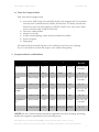
Volume III.G – Utilities Systems
November 1, 2011
G. Utilities Systems
1. Introduction
The following Utility System Standards provide requirements and guidelines for use by the
Consultant in the design and construction of the following campus-wide utility systems at the
University of Chicago:
a)
b)
c)
d)
e)
Chilled Water
High /Medium Pressure Steam and Condensate
Compressed Air
Utility Piping Identification
Vaults for Campus Utilities
This chapter shall apply to the campus-wide utility systems listed above from their point of
origin or existing connection to their entrance to buildings, including wall penetration and up to
and including the first shut-off valve inside the building. Steam utility shall include metering and
the first PRV up to and including safety relief valve; condensate utility shall include the main
building condensate receiver/pump, metering and drainage piping. Chilled water utility shall
include metering, chilled water bridge and heat exchanger (if applicable). Specific component
requirements for flash tanks, high pressure drips, condensate receivers, etc. shall comply with
provisions of the Mechanical section of these Standards. The Campus Utility system
components located inside new buildings may be included in the building bid/construction
package, subject to approval by the University.
Campus natural gas system additions and modifications shall be designed to comply with the
rules and regulations of Peoples Gas utility company.
The campus utility piping systems may be installed in tunnels and vaults or be direct-buried. The
type of installation shall be determined upon consideration of all major factors and anticipated
schedule for preventive maintenance and replacement of major system components; the final
determination shall be made in consultation with the University. The factors that shall be
considered:
•
•
•
•
•
•
Reliability of service, time back in service after a failure
Durability and life expectancy
Serviceability, preventive maintenance
Site limitations and surface improvements
Life-cycle cost
First cost
The Facilities Services Facility Standards (FS)2 is a living document which is subject to change.
Please refer to the latest version of the document in accordance with Exhibit C of the contract agreements.
1
Volume III.G – Utilities Systems
November 1, 2011
2. System Guidelines
The following major design criteria shall be used in implementation of these standards:
a) Chilled Water
1. Supply
a. Operating temperature
b. Operating pressure
45 ± 5 Degrees F.
150 psig maximum
2. Return
a. Operating temperature
b. Operating pressure
57 ± 5 Degrees F.
150 psig maximum
3. Design Temperature Differential
a. Preferred
b. Minimum
16 Degrees F.
12 Degrees F.
b) Steam and Condensate
1. Main and Southwest Campus Distribution
a. Operating temperature
460 Degrees F
b. Operating pressure
175 psig
Note: South Campus operating pressure is 80 psig
2. Medical Center Distribution
a. Operating temperature
b. Operating pressure
380 Degrees F
125 psig
3. Main Quadrangle, North Campus, Woodlawn Distribution
a. Operating temperature
355 Degrees F
b. Operating pressure
80 psig
4. Medium Pressure (Smaller buildings east of University Avenue)
a. Operating temperature
260 Degrees F
b. Operating pressure
20 psig
c) Compressed Air
1. North Campus
2. Main Quad/South Campus
80 psig
50 psig
d) Utility Piping Identification:
Provide piping labels to match existing. Comply with ASME piping identification standards.
The Facilities Services Facility Standards (FS)2 is a living document which is subject to change.
Please refer to the latest version of the document in accordance with Exhibit C of the contract agreements.
2
Volume III.G – Utilities Systems
November 1, 2011
e) Vaults for Campus Utilities
Each vault shall be equipped with:
•
•
•
•
•
•
Access door H1W (single leaf) and H2W (double leaf) equipped with T-316 stainless
steel slam lock as manufactured by Holiday Products Inc. of Orlando, Florida and a
Model T key lock with removable key in LEVEL-LOCK cover. Access door frame
and cover shall be rated for IDOT H-20 load.
University standard ladder
Adequate vent holes
Locally-switched lighting; switch shall be reachable from ladder
Service receptacle
Sump pump
All conduits shall be mounted high above floor and kept away from access openings.
Top of a vault shall be elevated with respect to the adjacent final grading.
3. Component Matrix and Guidelines
System
Installation
Piping
Valves
Testing
Chilled Water
Direct Buried
PS-3
VS-3
TCS-1
Tunnel/Vaults
PS-4
VS-2
TCS-1
Direct Buried
PS-1
Tunnel/Vaults
PS-2
Direct Buried
PS-1
Tunnel/Vaults
PS-2
Direct Buried
CAS-1
Tunnel/Vaults
CAS-1
Steam
Condensate
Return
Compressed
Air
Insulation Excavation /
Backfill
NONE
Site, Civil, and
Grounds*
IS-2
N/A
PS-1
Site, Civil, and
Grounds*
TS-3, CS-4
IS-1
N/A
NONE TS-3, CS-4
PS-1
Site, Civil, and
Grounds*
IS-1
N/A
NONE TS-2, CS-2
NONE
Site, Civil, and
Grounds*
CAS-1
NONE
N/A
NONE TS-3, CS-4
VS-1
VS-1
TS-3, CS-4
TS-2, CS-2
*NOTE: Provide a formal submittal that defines applicable excavation, trenching, dewatering,
backfill and compaction requirements with each utility project.
The Facilities Services Facility Standards (FS)2 is a living document which is subject to change.
Please refer to the latest version of the document in accordance with Exhibit C of the contract agreements.
3
Volume III.G – Utilities Systems
November 1, 2011
a) PS-1 Direct Buried Steam and Condensate Piping
1. Application:
Distribution of campus steam, condensate and high pressure steam drip return.
2. Manufacturers:
a. Perma-Pipe 500 modified to University requirements stated herein.
b. Rovanco 800 modified to University requirements stated herein.
c. Thermacor modified to University requirements stated herein.
3. Carbon steel seamless carrier pipe:
a. Steam: extra strong; piping components shall meet 300 psig rating.
b. Pumped condensate: extra strong; piping components shall meet 150 psig rating.
c. High pressure drip return: double extra strong; piping components shall meet 300 psig
rating.
d. Fittings: seamless steel, material and wall thickness to match adjoining piping.
e. Joints: butt or socket welded.
f. Pitched in the direction of steam flow, when possible.
g. Take-off from existing pipe: by Weldolet or Sockolet, up to 50% of main pipe; take-off
with tee if 50% of main pipe or greater.
4. Insulation:
Pre-molded perlite blocks (each block not to exceed 2 inch thick with joints overlapped) and
continuously wrapped within an intermediate casing made of sheet metal and strapped with
metal clamps; acceptable sheet metal are matching galvanized steel, aluminum or stainless steel.
Apply mastic between all perlite joints. Provide adequate insulation thickness so that
intermediate casing temperature to be less than 207 Degrees F.
5. Intermediate casing:
Carbon steel 10-gauge thick with spacers separating inner pipe from intermediate casing.
Provide passive catholic protection with buried magnesium anodes; provide isolation flanges
to segregate building systems from buried piping.
6. Outer jacket:
Casing shall be covered with foam insulation and smooth-bore without seam mark
polyethylene jacket 175 mil thick. Insulation thickness (1.5 inch minimum, 4 inch
maximum) shall be economically justified. Outer jacket temperature shall be less than 100F.
7. Field joints:
Meet same standard as the above. Outer joint shall be heat applied polyethylene shrink
wrap.
8. Piping flexibility analysis:
Piping shall be design to meet ASME B31.1 requirements, utilize cold springing as
applicable; pre-stressed design is not allowed. Submit for University review.
The Facilities Services Facility Standards (FS)2 is a living document which is subject to change.
Please refer to the latest version of the document in accordance with Exhibit C of the contract agreements.
4
Volume III.G – Utilities Systems
November 1, 2011
9. Expansion compensation:
a. Preferred method: pipe loops
b. Acceptable method: expansion joints, inside stem vault only.
c. Install anchors in vault only, anchors on direct-buried piping are not allowed.
10. Piping entering concrete vault or basement:
Adequately sized, sleeved penetration shall be provided to allow the installation of link seal
to the outer jacket. Link seal shall be serviceable from inside. Fill the exterior of the opening
with Bentonite plug; provide 2 inch Bentonite hydro-grout seal. Sheet-wrap casement pipe
exterior and terminate it on wall with cold tar seal.
11. Quality assurance:
After installation and prior to system startup, open the drain valves at each vault and remove
any water inside the jacketing. Blow dry compressed air into the jacket while venting the
other end to remove any moisture that may have been trapped inside the jacket during
construction.
b) PS-2 Steam and Condensate Piping in Tunnels/Vaults
1. Application:
Distribution of campus steam, condensate and high pressure steam drip return.
2. Carbon steel seamless pipe:
a. Steam: extra strong weight piping pressure shall meet 300 psig rating.
b. Pumped condensate: extra strong; piping pressure shall meet 300 psig rating.
c. High pressure drip return: double extra strong; piping pressure shall meet 300 psig
rating.
d. Fittings: seamless steel, material and wall thickness to match adjoining piping, pressure
ratings: 300 psi over 2 inch, 800 psi for 1 to 1 ½ inch and 2000 psi for 1 inch or less pipe
diameter.
e. Joints: 2-1/2“ and larger butt welded, 300 psi rating; 2” and smaller socket welded, 2000
psi rating.
f. Take-off from existing pipe: by Weldolet or Sockolet when diameter of branch pipe is
lesser than 50% of that of main, pressure rating to match joints.
g. Flanged connections: at valves and expansion joints only.
h. Flange bolts: SAE Grade 8 or ASTM A193 B7 bolts with 2H nuts.
3. Piping flexibility and safety analysis:
a. Steam and condensate piping shall be design to meet ASME B31.1 requirement.
b. Indicate displacements, forces and moments at each pipe hanger and support location.
c. Determine bending moments for flange bolts torque calculations.
d. Provide steam safety relief calculations.
e. Utilize cold springing as applicable; pre-stressed design is not allowed.
f. Submit calculations to the University for review.
The Facilities Services Facility Standards (FS)2 is a living document which is subject to change.
Please refer to the latest version of the document in accordance with Exhibit C of the contract agreements.
5
Volume III.G – Utilities Systems
November 1, 2011
4. Expansion compensation:
a. Preferred method: pipe loops
b. Acceptable method: expansion joints may be proposed to the University if pipe loops are
not feasible.
5. Hangers and supports:
Installation is to be in accordance with mechanical provisions of the standards. All supports
shall be floor- or wall-mounted, hanging from tunnel or vault roof is not allowed. Provide
design for piping supports and attachments to building structures. Submit design and
calculations to the University for review.
6. Inside the concrete vaults or basement:
a. Provide factory designed cover plate to cover the end between the pipe and outer jacket.
b. Provide 1 inch warm up bypass line with steel gate valve rated at 2000 psi at 400 Degrees
F. at the building main isolation valve.
c. Provide a ball valve at the ¾ inch drain connection.
d. Provide a pipe connected to the ¾ inch vent connection; run it toward to the top of the
vault or basement and terminate with a gooseneck.
e. Provide steam trap assembly to drain condensate from both sides of the isolation valve.
f. Provide Spence PRV for sizes 4” and under. Use Fisher PRV for 6” and larger. Selfregulating SRV, drip pan elbow. Provide PRV and SRV sizing and calculations for
review.
g. Provide steam and condensate metering at the first PRV.
h. Provide the main building condensate receiver/pump, metering and drainage piping.
7. Quality assurance:
After installation and prior to system startup, open the drain valves at each vault and remove
any water inside the jacketing. Blow dry compressed air into the jacket while venting the
other end to remove any moisture that may have been trapped inside the jacket during
construction.
c) PS-3 Direct Buried Chilled Water Piping
1. Application:
Distribution of campus chilled water.
2. High Density Polyethylene (HDPE) pipe:
a. Minimum pressure rating: 160 psig
b. Carrier pipe: SDR-11 min.
c. Fittings: SDR-9 min.
d. Joints: butt fusion welded with fusion machine. Electro-fusion welding can be proposed
in lieu of fusion if use of fusion machine is not feasible; prior approval from University
is required.
e. Take-off from existing pipe: construction and ratings to match joints
f. Flanged connections: at valves only
The Facilities Services Facility Standards (FS)2 is a living document which is subject to change.
Please refer to the latest version of the document in accordance with Exhibit C of the contract agreements.
6
Volume III.G – Utilities Systems
November 1, 2011
3. Minimum depth of top of piping shall be 5 feet below final surface grade. Slope piping
upwards toward building, provide air vents at all high points. Generally, maximum depth of
bottom of piping shall not exceed 12 feet.
4. Direct-buried chilled water piping shall not require any insulation.
d) PS-4 Chilled Water Piping in Tunnels/Vaults
1. Application:
Distribution of campus chilled water system, other than direct buried.
2. Carbon steel seamless pipe:
a. Standard weight piping, pressure shall meet 300 psig rating.
b. Fittings: seamless steel, material and wall thickness to match adjoining piping, pressure
ratings 300 psi
c. Joints: 2-1/2 “and larger butt welded, 300 psi rating; 2” and smaller screwed or socket
welded, 300 psi rating.
d. Take-off from existing pipe: by Weldolet or Sockolet when diameter of branch pipe is
lesser than 50% of that of main, pressure rating to match joints.
e. Flanged connections: at valves and expansion joints only.
3. Piping flexibility analysis:
a. Chilled water piping shall be design to meet ASME B31.1 requirement.
b. Indicate displacements, forces and moments at each pipe hanger and support location.
c. Determine bending moments for flange bolts torque calculations.
d. Submit calculations to the University for review.
4. Expansion compensation:
a. Preferred method: pipe loops
b. Acceptable method: expansion joints, subject to approval by the University.
5. Hangers and supports:
Installation is to be in accordance with mechanical provisions of the standards. All supports
shall be floor- or wall-mounted, hanging from tunnel or vault roof is not allowed. Provide
design for piping supports and attachments to building structures. Submit design and
calculations to the University for review.
6. Inside the concrete vaults or basement:
a. Provide a ball valve at the 3 inch drain connection.
b. Provide a pipe connected to the 1 inch vent connection; run it toward to the top of the
vault or basement and terminate with a gooseneck.
7. Quality assurance:
After installation and prior to system startup, open the drain valves at each vault and remove
any water.
The Facilities Services Facility Standards (FS)2 is a living document which is subject to change.
Please refer to the latest version of the document in accordance with Exhibit C of the contract agreements.
7
Volume III.G – Utilities Systems
November 1, 2011
e) CAS-1 Compressed Air System
1. Application:
Distribution of campus compressed air.
2. Carrier pipe:
a. Tunnel piping: Type K copper with brazed joints 3 inches and smaller. Galvanized steel
4 inches and larger.
b. Underground direct burial piping: Polyethylene SDR-11, 150 psig Asahi/America TUB
124 blue pipe or approved equivalent (rated for gas service).
c. At each building or group of buildings: Type K refrigeration grade copper with brazed
joints and end caps and line size isolation ball valve, 1 inch minimum.
d. Piping inside steam vaults shall be insulated and jacketed.
3. Isolation, drain and vent valves:
Ball valves, 4” and Smaller: MSS SP-110, Class 150, 600-psi CWP, ASTM B 584 bronze
body and bonnet, 2-piece construction; chrome-plated brass ball, standard port for 1/2-inch
valves and smaller and conventional port for 3/4-inch valves and larger; blowout proof;
bronze or brass stem; Teflon seats and seals; threaded or brazed connections. Distribution
system isolation valves shall be placed in shallow manholes.
•
•
•
Operator: Steel handwheel for isolation valves and ¼ turn lever for drain and vent
valves.
Stem Extension: For valves installed in insulated piping.
Memory Stop: For operator handles.
4. Piping specialties:
a. Flow meter: with totalizer for local reading and remote campus BAS data collection.
b. Pressure regulator: cast iron body, stainless steel trim; specify connection size and outlet
pressure range, Fisher Pressure Reducing Regulator or approved equivalent.
c. Filtration at building entrance: line size; metal housing rated for 250 psig service;
differential pressure gauge; adjustable timer blow-down;
i.
Upstream Particulate filter: 5 micron element
ii. Downstream Coalescing filter: .01 micron element
iii. Provide isolation valves upstream and downstream of filter train
iv. Provide by-pass line with ball valve.
v. Acceptable manufacturers: Balston or Arrow Pneumatics High Flow Model
5. Hangers and supports:
Installation is to be in accordance with mechanical provisions of the standards. Each hanger
or support rod shall be fitted with a double not and a washer.
The Facilities Services Facility Standards (FS)2 is a living document which is subject to change.
Please refer to the latest version of the document in accordance with Exhibit C of the contract agreements.
8
Volume III.G – Utilities Systems
November 1, 2011
f) VS-1 Valves for Steam and Condensate Piping in Tunnels /Vaults
1. Gate valve:
a. 2“ or larger diameter. Bonny Forge ASME Class 300 (500 psi pressure rating at 400
Deg. F) flanged valve with cast steel body, bolted bonnet, Stellite seat ring, 13%
Chromium steel wedge, spiral SS graphite gasket, steel bearing, ductile iron hand
wheel; valve 2 inch to 6 inch shall be stem-mounted hand wheel operated; valves 8
inch and above shall be hand wheel gear operated with position indicator.
b. 1-1/2“ or smaller diameter. Bonny Forge ASME Class 800 (2000 psi pressure rating
at 400 Deg. F) socked welded valve with forged steel body, bolted bonnet, Stellite
seat ring, 13% Chromium steel wedge, steel bearing, ductile iron stem-mounted hand
wheel with position indicator.
c. Main isolation valve shall be provided on Steam and Condensate lines inside each
building within 5 feet from entering the building and at each take-off from mains. 1”
diameter warm-up bypass with a gate valve shall be provided at both sides of each
isolation valve.
2. Butterfly valve:
Flanged butterfly valve is allowed only when insufficient space exists for a gate valve 3
inches or larger diameter. Adams MAK triple-offset, ASME Class 300 (500 psi pressure
rating at 400 Deg. F) valve with cast steel body and hand wheel, bidirectional metal-to-metal
zero-leakage seal. Install valves to match direction of pressure.
3. Flange gaskets:
Provide Flexitallic Thermiculite stainless steel with inner and outer rings.
4. Steam trap assembly:
a. Armstrong trap, cast steel body
b. Provide trap on both sides of steam isolation valve
c. For each trap at any vertical drop of a steam pipe, provide a full size dirt leg with bottom
blow down and a gate valve; take-off to trap assembly shall be at least 6” above the
bottom of dirt leg
d. Provide test port downstream each stem trap
e. Provide union on each side of steam trap to facilitate its removal
f. Provide high pressure piped drip inside each vault
5. Bolts and nuts:
ASTM A193 B7 or SAE Grade 8 bolts with 2H nuts. Provide double-nuts, torque to the
applicable ASTM standard requirement, and re-tighten after start-up.
g) VS-2 Valves for Chilled Water Piping in Tunnels/Vaults
1. Manual valve:
a. Isolation Valves. Bray valve series 31H with cast iron body, 416 s.stl. stem, nylon coated
ductile iron disc; EPDM seat; class 125/150 bolt pattern; lug connection; 250 psi bubble
tight shut off and dead end service; valve 2 inch to 6 inch shall be lever operated; valves
The Facilities Services Facility Standards (FS)2 is a living document which is subject to change.
Please refer to the latest version of the document in accordance with Exhibit C of the contract agreements.
9
Volume III.G – Utilities Systems
November 1, 2011
8 inch and above shall be hand wheel gear operated; position indicator. Main isolation
valve shall be provided on Chilled Water Supply and Chilled Water Return lines inside
each building within 5 feet from entering the building.
b. Drain and vent valves. Ball valves, 2-1/2” and Smaller: MSS SP-110, Class 150, 600-psi
CWP, ASTM B 584 bronze body and bonnet, 2-piece construction; chrome-plated brass
ball, standard port for 1/2-inch valves and smaller and conventional port for 3/4-inch
valves and larger; blowout proof; bronze or brass stem; Teflon seats and seals; threaded
connections.
•
•
•
Operator: Steel handwheel.
Stem Extension: For valves installed in insulated piping.
Memory Stop: For operator handles.
2. Automated valve:
Bray series 31; 250 psi shut off, EPDM seat; actuator Bray series 92/93 rack and pinion
pneumatic actuator with hand wheel; size for 50 psi air; with Bray series 05 de-clutchable
manual over ride; Bray series 6A E/P positioner with position indicator; all other items same
as manual valve above.
Limit switch for remote status or control:
Bray model 50.
h) VS-3 Valves for Direct Buried Chilled Water Piping
1. Manual valve:
Pratt valve series HP-250II with ANSI B16.1, Class 250 ductile iron body, ASTM A-564
Type 630 condition H-1150 shaft extended to grade level, nylon coated ductile iron disc;
EPDM seat; class 125/150 bolt pattern; flanged connection; 250 psi bubble tight shut off
and dead end service; Manual actuators shall be of the traveling nut, self-locking type and
shall be designed to hold the valve in any intermediate position between fully open and fully
closed without fluttering or creeping. The actuator shall have mechanical stops that will
withstand and input torque of 450 ft/lb. against each stop. Manual isolation valve shall be
provided on Chilled Water Supply and Chilled Water Return lines outside of each building
within 5 feet from entering the building, at each street crossing and at each take-off from
mains. Terminate the shaft extension in a manhole buffalo box with cover to protect the
shaft from ground traffic.
2. Air Vent valve:
Apollo flanged ball valve in a manhole buffalo box with cover at grade to protect the shaft
from ground traffic. Vent piping shall be HDPE, fusion welded and flanged at connection to
ball valves.
3. Companion flange:
Provide ductile iron extensions to each side of valve, bolt to HDPE pipe flange with
stainless steel bolts and nuts, applicable gasket.
The Facilities Services Facility Standards (FS)2 is a living document which is subject to change.
Please refer to the latest version of the document in accordance with Exhibit C of the contract agreements.
10
Volume III.G – Utilities Systems
November 1, 2011
i) TCS-1 Chilled Water Piping Testing and Flushing Guideline
- Campus chilled water distribution direct-buried pipes (HDPE):
1. Hydro testing prior to backfill:
a. Fill piping with water and slowly increasing pressure and hold steady at 50 psi
increments to allow stretching of piping material and weather influence.
b. All joints shall be exposed all around and trench shall be dry so that joints can be
inspected for leak.
c. Pressure shall be maintained steady at 220 psig for 4 hours with no leak at the joints.
d. Pressure shall be brought down to 160 psig and left over night. All joints shall be
checked for leak the next morning.
e. Valves shall be closed one at the time and kept under steady pressure of 160 psig for 1
hour with no leak.
f. If there is no leak, lower the pressure to 50 psig. Re-torque bolts at valve flanges.
g. Backfill pipes with 50 psig fill pressure; do not backfill otherwise.
h. Record test.
2. Hydro testing after backfill:
a. At the end of the project, fill piping and slowly increasing pressure and hold steady at 50
psi increments.
b. Increase pressure to 220 psig and maintain steady for 4 hours.
a. Record test. This report shall be submitted to the University Mechanical Engineer before
system startup. This report shall be part of the commissioning document.
3. Flushing and cleaning:
a. Pipes stored at construction site shall have ends covered.
b. Do not connect new pipe to existing until the flushing and cleaning has been completed.
c. During the fusion process and after facing of pipe joint, pipes shall be separated to have
all “shaving ribbons” removed.
d. After installation pipes shall be filled with water and flushed.
e. Ends of supply and return pipes shall be connected after testing and flashing has been
completed.
f. Circulate water at 5 to 8 fps until no debris is caught at 5 micron strainer for 24 hours.
Provide flushing machine with adequately sized pump to provide the flow required to
reach stated velocities.
g. Record test.
The Facilities Services Facility Standards (FS)2 is a living document which is subject to change.
Please refer to the latest version of the document in accordance with Exhibit C of the contract agreements.
11
Volume III.G – Utilities Systems
November 1, 2011
- Campus chilled water distribution piping in tunnels and vaults (steel):
1. Hydro testing:
a. Prior to backfill of adjacent direct-buried piping, fill piping with water and slowly
increasing pressure and hold steady at 50 psi increments.
b. Pressure shall be maintained steady at 225 for 4 hours with no leak at the joints.
c. If there is no leak, lower the pressure to 50 psig. Re-torque bolts at valve flanges.
d. Re-test together with the adjacent direct-buried piping.
b. Record both tests. These reports shall be submitted to the University Mechanical
Engineer before system startup. These reports shall be part of the commissioning
document.
2. Flushing and cleaning:
a. Piping segments in vaults shall be flushed and cleaned following the procedure for
flushing and cleaning of the adjacent direct-buried pipe.
b. Cleaning procedure for mains in tunnels shall be developed by a Consultant specific to
each project and approved by the University.
j) TS-2 Pressure Test for Compressed Air Piping
1. General:
a. Piping system shall first be assembled and erected, then pressure tested and finally blowout and cleaned.
b. Lines open to atmosphere such as safety relief lines and lines downstream of the last
shutoff valve need not be tested. These lines shall be visually inspected to determine
that all joints are installed properly.
c. Pressure vessels and other equipment built and tested to codes and specifications need
not be tested.
d. If local or others codes and regulations are more stringent, they shall take precedent.
2. Preparation for testing:
a. At the time of testing, pipe metal temperature shall not be below 40F.
b. All pipe joints shall be visually inspected for proper installation.
c. All flanged, threaded and welded joints shall be left unpainted and un-insulated.
d. Pumps, compressors, heat exchangers, safety valves, flame arrestors, vessels, rupture
disks, self-contained regulators and any other equipment shall not be subjected to the
piping test pressure. The equipment shall be bypassed or disconnected, and pipe ends
blind flanged or removed and a spool piece inserted in its place.
e. When it is necessary, for practicality, to include a vessel or other equipment, the test
pressure shall not exceed the allowable cold limit of the equipment. Prior approval must
be obtained from the University Mechanical Engineer.
f. Piping connected to other lines (existing lines or lines installed by others) shall be
isolated or blanked off for testing.
The Facilities Services Facility Standards (FS)2 is a living document which is subject to change.
Please refer to the latest version of the document in accordance with Exhibit C of the contract agreements.
12
Volume III.G – Utilities Systems
November 1, 2011
g. Instrumentation piping shall be tested together with the piping system up to the block
valve nearest to the instrument. All instruments shall be excluded from the test by either
disconnecting the piping at the instrument and capping the pipe or closing the blocking
valve nearest the instrument.
h. Automatic control valve shall be in the open position unless provided with a by-pass
permitting application of pressure to both sides.
i. Expansion joints shall be provided with temporary restraints if required for the
additional pressure load under test, or they shall be isolated during the pressure test.
j. One or more calibrated indicating test gauges shall be installed in the piping to
coordinate the pressuring operation.
3. Test procedure:
a. The gas used as the test medium shall be clean, dry, oil-free air or nitrogen. Prior
approval must be obtained from the University Mechanical Engineer if an alternate test
gas is to be used. Alternate test gas must be nonflammable, nontoxic and harmless to
the piping material in the system.
b. Initially piping pressure shall be brought to 25 psig. If no leak is found, the pressure
shall be slowly increased in increments of 25 psig with 10 minutes allowed at the end of
each increment for equalization, until the test pressure is reached.
c. The test pressure shall be held for 4 hours continuously. Include additional time to
examine pipe joints and connections for leakage.
d. Piping systems shall be tested to 150 psig or 1.5 times operating pressure, whichever is
greater.
e. A soap solution shall be applied to all joints undergoing pneumatic pressure testing.
f. Leaks shall be marked and identified for repair. Major repairs or additions to the piping
system shall be retested. Minor repairs may be waived with the permission of the
University Mechanical Engineer. Repairs shall be inspected and observed for leaks.
g. System isolation valves shall also be tested for leaks.
h. Pressured shall be released gradually and discharged to a safe location upon completion
of the test. Systems shall be returned to their pretest condition. All items previously
removed, blocked off or disassembled shall be reinstalled, reassembled and made
operative.
4. Test Report:
a. Fill out a test report. This report shall be submitted to the University Mechanical
Engineer before system startup. This report shall be part of the commissioning
document.
k) TS-3 Testing of Steam and Condensate Piping
1. General:
a. Steam piping testing includes steam and condensate.
b. Piping system shall first be assembled and erected, and then pressure-tested and finally
blow-out and cleaned.
c. Do not install insulation to piping until testing is complete. Otherwise insulation shall be
removed for testing at the contractor’s expense.
The Facilities Services Facility Standards (FS)2 is a living document which is subject to change.
Please refer to the latest version of the document in accordance with Exhibit C of the contract agreements.
13
Volume III.G – Utilities Systems
November 1, 2011
d. Lines open to atmosphere such as safety relief lines and lines downstream of the last
shutoff valve need not be tested. These lines shall be visually inspected to determine
that all joints are installed properly.
e. Pressure vessels and other equipment built and tested to codes and specifications need
not be tested.
f. If local or others codes and regulations are more stringent, they shall take precedent.
2. Preparation for testing:
a. At the time of testing, pipe metal temperature shall not be below 40F.
b. All pipe joints shall be visually inspected for proper installation.
c. All piping systems shall be checked for adequate vent and drain connections.
d. All flanged, threaded and welded joints shall be left unpainted and un-insulated.
e. Heat exchangers, safety valves, flame arrestors, vessels, rupture disks, self-contained
regulators and any other equipment shall not be subjected to the piping test pressure.
The equipment shall be bypassed or disconnected, and pipe ends blind flanged or
removed and a spool piece inserted in its place.
f. When it is necessary, for practicality, to include a vessel or other equipment, the test
pressure shall not exceed the allowable cold limit of the equipment. Prior approval must
be obtained from the University Mechanical Engineer.
g. Piping connected to other lines (existing lines or lines installed by others) shall be
isolated or blanked off for testing.
h. All restrictions, such as flow nozzles and orifice plates, which interfere with filling,
venting or draining shall be removed from the piping.
i. Instrumentation piping shall be tested together with the piping system up to the block
valve nearest to the instrument. All instruments shall be excluded from the test by either
disconnecting the piping at the instrument and capping the pipe or closing the blocking
valve nearest the instrument.
j. Piping systems designed for steam shall be provided with additional temporary supports
if necessary to support the weight of the test liquid.
k. Spring hanger pipe supports shall have travel stops inserted.
l. Automatic control valve shall be in the open position unless provided with a by-pass
permitting application of pressure to both sides.
m. Expansion joints shall be provided with temporary restraints if required for the
additional pressure load under test, or they shall be isolated during the pressure test.
n. Piping systems subject to extended hydrostatic test periods shall be provided with a
protected device to relieve excess pressure due to thermal expansion.
o. One or more calibrated indicating test gauges shall be installed in the piping to
coordinate the pressuring operation. The location for test pressure gauges is at the
bottom of the system for liquid service and at the top of the system for steam service.
When test gauges are installed at the top of a system, care shall be taken to ensure that
over pressuring of the piping and piping components does not occur at the bottom of
the system due to the additional pressure imposed by the static head of the test media.
3. Test procedure:
a. Test fluid shall be clean water. A suitable filter shall be provided at the fill line if sand,
rust or other particles are present at the test water.
b. Another suitable fluid may be used if there is possibility of freezing.
The Facilities Services Facility Standards (FS)2 is a living document which is subject to change.
Please refer to the latest version of the document in accordance with Exhibit C of the contract agreements.
14
Volume III.G – Utilities Systems
November 1, 2011
c. Compressible fluid such as gas or air shall not be used.
d. Piping system shall be slowly filled with test fluid. All vents and other connections
which serve as vent shall be open during filling, so that all air is vented prior to applying
pressure.
e. Before test pressure is applied the piping must be allowed to assume approximately the
same temperature as the test fluid.
f. Test pressure shall be 400 psig for 175 psig/125 psig/80 psig steam and high pressure
condensate drip return, except for 80 psig-rated steam piping located North of Midway
street where the test pressure shall be 300 psig.
g. Valves shall be closed one at the time and kept under steady pressure of 300 psig for 1
hour with no leak.
h. Hydrostatic test pressure shall be 225 psig for all pumped condensate piping.
i. Hydrostatic test pressure shall be maintained steady for 4 hours with no noticeable loss
in pressure for a sufficient length of time to visually inspect all joints for leaks, but not
less than four hours.
j. There shall be no evidence of weeping or leaking.
k. Leaks shall be marked and identified for repair. Major repairs or additions to the piping
system shall be retested. Minor repairs may be waived with the permission of the
University Project manager. Repairs shall be inspected and observed for leaks.
l. System isolation valves shall also be tested for leaks.
m. Upon completion of the test, systems shall be drained and returned to their pretest
condition. All items removed, blocked-off or disassembled shall be reinstalled,
reassembled and made operative as required.
4. All campus steam and condensate distribution piping shall require radiographic testing of the
welds. Other piping to be tested shall be defined by the project requirements.
The piping contractor that performs the pipe welding shall provide the quality of weld to
pass such inspection and include all preparation work for testing. The contractor will hire
the testing agency to inspect 20% of the welds. Welds to be tested shall be chosen by the
University assisted by the consulting engineer. Acceptance criteria for the radiographic test
shall be per ASME B 31.1 paragraph 136.4.5. If there are any failed welds identified in the
first 20%, another 20 % sample will be taken. If another failure is found in the 20% sample,
testing of all welds will be required. The piping contractor pays for the testing of welds and
all work to repair the welds.
5. Test Report:
Fill out a test report. This report shall be submitted to the University Project Manager
before system startup. This report shall be part of the commissioning document.
The Facilities Services Facility Standards (FS)2 is a living document which is subject to change.
Please refer to the latest version of the document in accordance with Exhibit C of the contract agreements.
15
Volume III.G – Utilities Systems
November 1, 2011
l) CS-2 Gas Piping Blow-out and Cleaning
1. General:
a. Piping system shall first be assembled and erected, then pressure tested and finally blowout and cleaned.
b. Do not install insulation to refrigerant and ammonia piping until testing is complete.
2. Preparation for Blow-out:
a. All pipe joints and tap-ins shall be visually inspected for proper installation and
continuity.
b. All welds in the carbon steel portion of the pipe system shall be hammered prior to the
blow-out operation.
c. Provide temporary connections to compressed air for blow-out.
d. Equipment that has restricted flow passages or inaccessible areas where scale or particles
could collect shall be by-passed or removed and replaced by a spool piece.
e. All instrument lines shall be disconnected during and blow-out and cleaning operations
and reconnected at the end of the operations.
f. All low points and dirt legs shall have temporary blow-off valves.
3. Blow-out procedure:
a. Piping system shall be blown through with oil-free compressed air at high velocity to
remove all foreign matter.
b. Care shall be taken such that the stream of air leaving the (temporary) discharge point
dissipates harmlessly. Sign must be posted and personnel warned at the discharge area.
c. Upon completion of blow-out operation, all temporary hoses, fittings and auxiliaries
items shall be removed from the piping system.
d. Piping system shall be returned to the pre-blow-out condition.
4. Piping cleaning procedure:
a. After piping blow-out, clean system with a detergent solution.
b. Recalculate the solution through the system for at least two hours.
c. If recirculation is not possible, fill the system completely with hot detergent solution and
allow fifteen minutes of contact time. Drain and replace with fresh solution. Repeat this
procedure for eight times.
d. Flush the system continuously for one hour with fresh water. Each use point shall be
flushed thoroughly.
e. Test the water used for flushing for phosphate concentration, conductivity and pH.
f. Test the flush water from each point of use for concentration, conductivity and pH.
g. When readings of the flush water and the incoming water for flushing are the same,
drain the system.
h. Blowout the system with oil-free compressed air. Purge from all outlets in the system.
i. Upon completion, all temporary hoses, fittings and auxiliaries shall be removed from the
system piping.
j. Equipment and piping shall be returned to the pre-cleaning condition.
The Facilities Services Facility Standards (FS)2 is a living document which is subject to change.
Please refer to the latest version of the document in accordance with Exhibit C of the contract agreements.
16
Volume III.G – Utilities Systems
November 1, 2011
m) CS-4 Steam and Condensate Piping Flushing and Cleaning
1. General:
a. Piping system shall first be assembled and erected, and then pressure tested and finally
flushed and cleaned.
b. Do not install insulation to the piping until testing is complete.
2. Preparation for flushing and cleaning:
a. Piping system shall be visually inspected for proper installation and continuity.
b. All welds in the carbon steel piping shall be hammered.
c. Equipment that has restricted flow passage or areas where sediment could collect shall
either be bypassed or removed and replaced by a spool piece.
d. All instrument lines shall be disconnected during blowout and cleaning operations and
reconnected at the end of the operations.
e. All low points and dirt legs shall have temporary blow-off valves.
3. Flushing procedure:
a. Flush through with clean fresh water to assure complete removal of all foreign matter.
b. Temporary discharge point of the line shall be in a safe location and discharge stream
shall dissipate harmlessly.
c. All personnel shall be warned and kept clear of the discharge area during flushing
operation.
a. Circulate water at 5 to 8 fps until no debris is caught at 5 micron strainer for 24 hours.
Provide flushing machine with adequately sized pump to provide the flow required to
reach stated velocities.
4. Steam Thermo Cycling:
a. Open all valves in the steam system piping including the branch lines except the valve at
source and valves at equipment.
b. Open all piping drain valves including those at steam trap strainers.
c. At the control valves, if there is a by-pass line, open the by-pass valve but keep the block
valves closed. If there is no by-pass line, open the control valve to the wide- open
position.
d. Crack open the warm-up bypass valve and slowly warm up the piping system.
e. Raise the steam pressure in the system by gradually throttling the drain valves
discharging steam.
f. Do not raise the steam pressure by further opening the main steam valve.
g. One by one, open the downstream valves at the steam traps and allow formed
condensate to run into the condensate header. Run condensate from header to drain.
h. Leave the system under pressure for one hour. Close the steam valve and allow the
system to cool down and to depressurize by condensation.
i. Repeat the thermo cycle 2 more times.
5. Condensate piping cleaning:
a. Complete cleaning of steam piping before flushing of condensate piping.
b. Remove steam traps and connect a water hose to the downstream piping of a trap and
flush towards the condensate receiver or the condensate header.
The Facilities Services Facility Standards (FS)2 is a living document which is subject to change.
Please refer to the latest version of the document in accordance with Exhibit C of the contract agreements.
17
Volume III.G – Utilities Systems
November 1, 2011
c. Drain the condensate receiver to floor drain and the condensate header to an approved
drainage point.
d. When all trap discharge lines have been flushed, flush main condensate header with
temporary piping or hose connection from the nearest city water main.
e. Provide temporary piping or hose from the end of the condensate header being flushed
to an approved drainage point.
f. Connect steam and condensate at both ends. Circulate water at 5 to 8 fps until no debris
is caught at 5 micron strainer for 24 hours. Provide flushing machine with adequately
sized pump to provide the flow required to reach stated velocities.
6. Flush the condensate header with water from the city water main or an adequately sized
flashing machine until a clear flow is obtained; method to be determined by a specific project
design engineer.
7. Upon completion of flushing and cleaning operations, all temporary piping, pumps, strainers
and baskets shall be removed from the piping system unless otherwise specified. Equipment
and piping shall be returned to their pre-flush condition and permanent strainers must be
cleaned.
n) IS-1 Steam and Condensate Piping Insulation in Tunnels/Vaults
1. Insulation material for piping:
a. In tunnels steam and condensate piping insulation shall be single or multiple of 2 inch
thick or 1-1/2 inch thick 2 piece pre-molded perlite block(s) with seams overlapped and
staggered joints, tied together with wire; apply mastic at all joints between blocks. Wrap
insulation with Alpha Matric rewettable material. After dried, cover with Childer CP10
with mesh to30 mil wet thickness with 60% solid; after dried cover with another 30 mil
wet thickness of CP10 with mesh.
b. At location exposed to water dripping, provide a 30 mil thick aluminum jacketing with
aluminum straps, in addition to above.
2. Thickness:
175 psig steam:
Condensate drip line:
80 psig steam:
Condensate drip line:
Pipe size
8 inch
1 inch
Thickness
4 inch
1-1/2 inch
8 inch
4 inch
1 inch
4 inch
3 inch
1-1/2 inch
The above thicknesses are provided as a guideline. Generally it is acceptable to match
thickness of existing insulation. The intent is to provide an economic thickness to minimize
heat loss and for personnel protection. The surface temperature should not exceed 100F in
most instances.
The Facilities Services Facility Standards (FS)2 is a living document which is subject to change.
Please refer to the latest version of the document in accordance with Exhibit C of the contract agreements.
18
Volume III.G – Utilities Systems
November 1, 2011
Where the new insulation meets with the existing, there should be a uniform transition
between the new and existing insulation. Repair damage to existing nearby insulation due to
piping demolition work.
Properly selected Aerogel Pyrogel insulation with mastic and jacketing may be considered for
use in vaults prone to flooding.
3. Removable insulation for PRV’s, strainers and valves:
a. 17 oz per square yard Teflon impregnated premium fiber-cloth on both sides with side
gusset
b. 6 lb density type E glass, 2 inch uncompressed thickness with no binder within
c. locate longitudinal seam at gravitational bottom
d. where removable insulation meets permanent insulation, removable insulation shall butt
against permanent one with 3 inch Teflon flap strapped around permanent one with belt,
double D rings and Velcro to hold flap; if butt joint is not practical, then removable
insulation must have a 3 inch overlap over permanent insulation; provide belt, double D
rings and Velcro to tighten the ends
e. Use Teflon coated fiberglass thread starting and ending the needle under (not above) the
insulation
f. Stainless steel pin and washer
g. Stainless steel double D rings and straps with Velcro
h. 1 in wide strap for 6 inch pipes and under
i. 1-1/2 in wide strap for 8 inch pipes and over
j. Removable insulation vendor list:
• Advanced Thermal Corporation
• Remco Technology
• DASS Corporation
• DESCO
• Insulation Concepts
4. No insulation required:
Steam traps and unions do not require insulation. Trap assembly at drip lines between
isolation valves do not require insulation. However, drip leg shall be insulated to and
excluding the bottom cap.
o) IS-2 Chilled Water Piping Insulation in Tunnels/Vaults
1. Insulation material:
2-piece pre-molded polyisocyanurate (pink color, not melon color) with all service jacket
(ASJ) white kraft paper outside and aluminum inside.
2. Thickness:
1 inch thick for 4 inch pipe and under
1-1/2 inch thick for 6 inch pipe and over
The Facilities Services Facility Standards (FS)2 is a living document which is subject to change.
Please refer to the latest version of the document in accordance with Exhibit C of the contract agreements.
19
Volume III.G – Utilities Systems
November 1, 2011
3. Seams:
Apply ASJ adhesive tape continuously along all longitudinal seams and brush with white
mastic. Apply ASJ adhesive tape continuously around all transverse seams and brush with
white mastic. Brush all ends of insulation with white mastic to form continuous vapor
barrier.
4. Insulation at hangers and supports:
Provide aluminum shield extending at least 6 inch each side of hanger; hanger must not be in
contact of pipe; it must be at the outside of the shield.
5. Protective jacketing:
Provide protective PVC jacketing where insulation is prone to damage and in high humidity
areas. Provide 15 mil thick PVC jacketing to covering over the all service jacketed
polyisocyanurate insulation; apply PVC jacketing at end of insulation; glue and seal all joints
continuously.
6. Execution:
a. Piping must be at room temperature and surface must be dry with no condensation
when installing insulation.
b. Wipe ASJ surface with a clean cloth to remove dust before applying adhesive tape.
c. Do not use staples; there should be no items breaking the ASJ surface; the ASJ surface
forms a continuous vapor seal against moisture.
d. Check entire installation for any puncture or tearing of ASJ. Repair by brushing with
ASJ tape and apply mastic.
e. At wall penetrations butt insulation with ASJ tight against the wall; provide PVC
jacketing material to form a gusset plate (a collar similar to the shape of a pipe flange)
around the insulation and seal between insulation and wall.
The Facilities Services Facility Standards (FS)2 is a living document which is subject to change.
Please refer to the latest version of the document in accordance with Exhibit C of the contract agreements.
20