1
FlexSEA: Flexible, Scalable Electronics Architecture for
Wearable Robotic Applications
by
Jean-François Duval
B.Eng., Electrical Engineering
Université de Sherbrooke, 2012
Submitted to the Program in Media Arts and Sciences,
School of Architecture and Planning,
In partial fulfillment of the requirements for the degree of
Master of Science
at the
Massachusetts Institute of Technology
June 2015
Licensed under Creative Common Attribution-NonCommercial-ShareAlike
CC BY-NC-SA 2015 – Jean-François Duval
Signature of Author: _____________________________________________________________
Program in Media Arts and Sciences
May 8th, 2015
Certified by: ___________________________________________________________________
Hugh Herr, Ph.D.
Associate Professor of Media Arts and Sciences
Thesis Supervisor
Accepted by:___________________________________________________________________
Prof. Pattie Maes
Academic Head
Program in Media Arts and Sciences
2
FlexSEA: Flexible, Scalable Electronics Architecture for Wearable Robotic Applications
by
Jean-François Duval
Submitted to the Program in Media Arts and Sciences,
School of Architecture and Planning, on May 8, 2015
in partial fulfillment of the requirements for the degree of
Master of Science
Abstract
The work of this thesis aims to enable the fast prototyping of multi-axis wearable robotic systems
by developing a new modular electronics system. The flexible, scalable electronics architecture
(FlexSEA) developed for this thesis fills the void between embedded systems used in commercial
devices and in research prototypes. This system provides the required hardware and software
for precise motion control, data acquisition, and networking. Scalability is obtained through the
use of fast industrial communication protocols between the modules, and the standardization of
the peripheral interfaces. Hardware and software encapsulation is used to provide highperformance, real-time control of the actuators while keeping the high-level control
development fast, safe and simple.
The FlexSEA kits are composed of two custom circuit boards (advanced brushless motor driver
and microcontroller board), one commercial embedded computer, a complete software stack
and documentation. During its development it has been integrated into a powered prosthetic
knee as well as an autonomous ankle exoskeleton. To assess the usability of the FlexSEA kit, a
new user successfully used a kit to read sensors and control an output device in less than three
hours. FlexSEA simplifies and accelerates wearable robotics prototyping.
Thesis Supervisor: Hugh Herr, Ph.D.
Title: Associate Professor of Media Arts and Sciences
3
4
FlexSEA: Flexible, Scalable Electronics Architecture for
Wearable Robotic Applications
by
Jean-François Duval
The following served as readers on this thesis committee:
Research advisor:_______________________________________________________________
Hugh Herr, Ph.D.
Associate Professor of Media Arts and Sciences
Program in Media Arts and Sciences
Thesis Supervisor
Thesis supervisor:_______________________________________________________________
Joseph Paradiso, Ph.D.
Associate Professor of Media Arts and Sciences
Program in Media Arts and Sciences
Thesis supervisor:_______________________________________________________________
David Perreault, Ph.D.
Professor of Electrical Engineering
Electrical Engineering and Computer Science (EECS)
5
Table of Contents
Abstract ........................................................................................................................................... 3
1
Introduction ........................................................................................................................... 13
2
System Design........................................................................................................................ 18
2.1
Combining architectures ................................................................................................ 18
2.2
FlexSEA: core ideas and principles ................................................................................. 19
2.3
Subsystems ..................................................................................................................... 19
2.3.1
FlexSEA-Plan ............................................................................................................ 20
2.3.2
FlexSEA-Manage ..................................................................................................... 20
2.3.3
FlexSEA-Execute ...................................................................................................... 20
2.4
System Architecture ....................................................................................................... 20
2.5
System-wide technical decisions.................................................................................... 22
2.5.1
FlexSEA-Plan: Embedded computer ....................................................................... 22
2.5.2
Communication: hardware ..................................................................................... 23
2.5.3
Communication: software ...................................................................................... 23
2.5.4
Software .................................................................................................................. 24
2.6
3
Design solutions – short answers ................................................................................... 24
Hardware design .................................................................................................................... 27
3.1
FlexSEA-Execute ............................................................................................................. 27
3.1.1
PSoC 5 LP Microcontroller ...................................................................................... 29
3.1.1.1
Microcontroller selection ................................................................................ 29
3.1.1.2
Programmable System on Chip (PSoC) ............................................................ 31
3.1.2
PSoC 4 Safety Co-Processor .................................................................................... 32
3.1.3
Brushless DC Motor ................................................................................................ 34
3.1.3.1
Half-bridges ..................................................................................................... 36
3.1.3.2
Motor current sensing ..................................................................................... 39
3.1.3.3
Shorted-leads protection................................................................................. 40
3.1.4
RS-485 ..................................................................................................................... 43
3.1.5
Strain Gauge Amplifier ............................................................................................ 45
3.1.6
Clutch ...................................................................................................................... 48
3.1.6.1
P-MOSFET power dissipation .......................................................................... 49
3.1.6.2
Level shifting .................................................................................................... 50
6
3.1.7
IMU.......................................................................................................................... 50
3.1.8
IO Protections ......................................................................................................... 51
3.1.9
User interface.......................................................................................................... 53
3.1.10
Power Supplies ........................................................................................................ 55
3.1.10.1
Brown-out protections .................................................................................... 55
3.1.10.2
Low voltage power supplies ............................................................................ 56
3.1.10.3
LM25011 10V 500mA ...................................................................................... 58
3.1.10.4
TPS62163 5V 500mA........................................................................................ 59
3.1.11
3.2
4
Future Work and Circuit Modifications .................................................................. 60
FlexSEA-Manage ............................................................................................................. 61
3.2.1
Microcontroller ....................................................................................................... 63
3.2.2
Interface to Plan...................................................................................................... 64
3.2.3
Inputs and Outputs ................................................................................................. 67
3.2.3.1
Analog Inputs with Programmable Features ................................................... 67
3.2.3.2
Digital Inputs & Outputs .................................................................................. 69
3.2.3.3
Power Outputs ................................................................................................. 70
3.2.4
IMU.......................................................................................................................... 71
3.2.5
FLASH ...................................................................................................................... 71
3.2.6
User Interface ......................................................................................................... 73
3.2.7
RS-485 ..................................................................................................................... 74
3.2.8
Power ...................................................................................................................... 75
3.2.9
Future Work and Circuit Modifications .................................................................. 76
Software Design ..................................................................................................................... 77
4.1
Communications and networking .................................................................................. 77
4.1.1
Application Layer .................................................................................................... 78
4.1.2
Data-link Layer ........................................................................................................ 80
4.1.3
Physical Layer .......................................................................................................... 81
4.1.4
Receiving commands .............................................................................................. 81
4.1.5
Hierarchy ................................................................................................................. 82
4.1.6
Special Commands .................................................................................................. 82
4.2
FlexSEA-Execute ............................................................................................................. 82
4.2.1
Organization and timings ........................................................................................ 83
4.2.2
BLDC Commutation ................................................................................................. 86
7
4.2.3
Current controller ................................................................................................... 90
4.2.4
Impedance controller.............................................................................................. 94
4.2.5
Trapezoidal trajectory generation .......................................................................... 95
4.3
FlexSEA-Manage ............................................................................................................. 96
4.4
FlexSEA-Plan ................................................................................................................... 97
4.4.1
Displaying and logging data .................................................................................... 97
4.4.2
High-level state machine in C ................................................................................. 98
4.4.3
Interfacing with higher level languages ................................................................ 100
4.5
5
Future Work ................................................................................................................. 102
Unit tests.............................................................................................................................. 104
5.1
FlexSEA-Execute ........................................................................................................... 104
5.1.1
Motor Half-Bridge Load test ................................................................................. 104
5.1.2
Strain Gauge Amplifier Force Calibration ............................................................. 106
5.1.3
Power Supplies ...................................................................................................... 106
5.1.3.1
Preliminary qualification ............................................................................... 106
5.1.3.2
10V SMPS Load Testing ................................................................................. 107
5.1.3.3
5V SMPS Load Testing ................................................................................... 109
5.1.4
5.2
Safety Features ..................................................................................................... 110
5.1.4.1
Watchdog Clock ............................................................................................. 110
5.1.4.2
Over-temperature ......................................................................................... 112
5.1.4.3
+VB Voltage Range ........................................................................................ 113
5.1.4.4
Disconnected Battery .................................................................................... 114
FlexSEA-Manage ........................................................................................................... 115
5.2.1
Level shifting – FlexSEA-Plan and FlexSEA-Manage Interface .............................. 115
5.2.1.1
5.2.2
5.3
6
Analog Inputs With Programmable Features ................................................ 116
Power Multiplexer and Linear Regulator Load Test ............................................. 118
System Benchmarks ..................................................................................................... 120
5.3.1
SPI Frequency and Data Rate ................................................................................ 120
5.3.2
Communication – Plan & Execute......................................................................... 121
5.3.3
Communication – Manage & Execute .................................................................. 123
5.3.4
Data Logging.......................................................................................................... 125
Application/test cases ......................................................................................................... 128
6.1
Clutched Series Elastic (CSEA) Knee ............................................................................. 128
8
6.2
7
Autonomous Exoskeleton ............................................................................................ 129
Evaluation and Results......................................................................................................... 130
7.1
Evaluation Criteria (legacy) .......................................................................................... 130
7.2
Evaluation Criteria ........................................................................................................ 130
7.3
Results .......................................................................................................................... 132
8
Conclusion ........................................................................................................................... 134
9
References ........................................................................................................................... 135
10
Annexes ........................................................................................................................... 137
10.1 Glossary ........................................................................................................................ 137
10.2 Execute Schematic ....................................................................................................... 139
10.3 Manage Schematic ....................................................................................................... 153
10.4 User Study .................................................................................................................... 165
10.5 User Manual ................................................................................................................. 167
9
Table of Figures
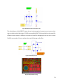
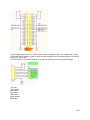
Figure 1 Microcontroller based architecture example [1]............................................................ 14
Figure 2 Embedded computer based architecture example [2] ................................................... 14
Figure 3 FlexSEA System Architecture: 1 DOF .............................................................................. 21
Figure 4 FlexSEA System Architecture: 1 axis 2 DOF .................................................................... 21
Figure 5 FlexSEA-Execute 0.1 Hardware ....................................................................................... 27
Figure 6. FlexSEA-Execute System Diagram .................................................................................. 28
Figure 7 PSoC 5 ad - excellent visualization .................................................................................. 31
Figure 8 PSoC Families .................................................................................................................. 31
Figure 9 FlexSEA-Execute hardware safety features diagram ...................................................... 33
Figure 10 PWM signals passing through the Safety-CoP .............................................................. 34
Figure 11 BLDC schematic - top level............................................................................................ 34
Figure 12 BLDC sensors (phase voltage & temperature) .............................................................. 35
Figure 13 +VB Decoupling capacitors ........................................................................................... 35
Figure 14 H-Bridge circuit ............................................................................................................. 36
Figure 15 MOSFET vs IGBT: when to use ...................................................................................... 36
Figure 16 Half-bridge on Execute (1 of 3) ..................................................................................... 37
Figure 17 The 3 channels use the same compact layout (B highlighted) ..................................... 39
Figure 18 Spice simulation, ±20A motor current sensing ............................................................. 40
Figure 19 Shorted-leads protection implemented with depletion mode MOSFETs .................... 41
Figure 20 Shorted-leads protection: negative voltage generation and gate control ................... 41
Figure 21 Spice simulation, voltage inverter ................................................................................ 42
Figure 22 One of the 3 RS-485 transceivers present on FlexSEA-Execute ................................... 43
Figure 23 RS-485 Modes: synchronous/asynchronous, half- or full-duplex ................................ 43
Figure 24 TINA-TI Spice simulation of the two stage differential amplifier design ...................... 45
Figure 25 CMRR vs Frequency, TI INA331/2331 instrumentation amplifier ................................ 46
Figure 26 Input: filtering and protection ...................................................................................... 46
Figure 27 Two stage amplification ................................................................................................ 47
Figure 28 PSoC Programmable Analog Blocks - Strain Gauge Amplifier ...................................... 47
Figure 29 Clutch driver schematic ................................................................................................ 48
Figure 30 IMU schematic .............................................................................................................. 51
Figure 31 External I/O protection circuit ...................................................................................... 51
Figure 32 Expansion connector..................................................................................................... 52
Figure 33 TPD4E004 ESD Clamping ............................................................................................... 53
Figure 34 ESD diode routed right under the Expansion connector .............................................. 53
Figure 35 RGB LED and Green "heartbeat" LED............................................................................ 54
Figure 36 USB ESD protection ....................................................................................................... 54
Figure 37 USB protection routing ................................................................................................. 54
Figure 38 Power Supplies Schematic ............................................................................................ 55
Figure 39 Brownout protection .................................................................................................... 56
Figure 40 10V 500mA SMPS .......................................................................................................... 58
Figure 41 Compact routing using polygon pours .......................................................................... 58
10
Figure 42 5V 500mA SMPS ............................................................................................................ 59
Figure 43 Compact routing using polygon pours .......................................................................... 59
Figure 44 FlexSEA-Manage 0.1...................................................................................................... 61
Figure 45 Manage 0.1 Hardware .................................................................................................. 62
Figure 46 STM32F4 sub-families ................................................................................................... 64
Figure 47 MiddleMan 0.1 (predecessor to Manage 0.1) on top of a BeagleBone Black .............. 65
Figure 48 Interface to Plan ............................................................................................................ 65
Figure 49 Level translation, SPI ..................................................................................................... 66
Figure 50 Level shifting, external reset signal............................................................................... 66
Figure 51 Expansion connector..................................................................................................... 67
Figure 52 AN0 & AN1: 1/10kHz LPF, G=1 ...................................................................................... 68
Figure 53 AN2 & AN3: 1/10kHz LPF, 1<G<10 ................................................................................ 68
Figure 54 AN4 & AN5: Buffered input .......................................................................................... 68
Figure 55 AN6 & AN7: Programmable voltage divider ................................................................. 69
Figure 56 Protected Digital IO ....................................................................................................... 69
Figure 57 1 of 2 power outputs .................................................................................................... 70
Figure 58 FLASH Memory.............................................................................................................. 71
Figure 59 User input...................................................................................................................... 73
Figure 60 RS-485 #1 3 transceivers ............................................................................................... 74
Figure 61 Autoswitch Power Mux and 3.3V LDO Regulator ......................................................... 75
Figure 62 OSI model ...................................................................................................................... 77
Figure 63 Payload bytes ................................................................................................................ 80
Figure 64 Packaged Payload ......................................................................................................... 80
Figure 65 Visual representation of the function timings .............................................................. 84
Figure 66 Unipolar 4-Quadrant PWMs - Texas Instruments ........................................................ 86
Figure 67 FlexSEA-Execute Motor Control (PSoC Diagram).......................................................... 89
Figure 68 PWM signals - rotating BLDC motor ............................................................................. 89
Figure 69 Load test bench, equivalent to a stalled Maxon brushless motor ............................... 93
Figure 70 Current PID setpoint versus measured phase current (kp = 50, ki = 50) ...................... 94
Figure 71 First implementation of an Impedance Controller (2014)............................................ 94
Figure 72 Calculated trajectory: acceleration, speed and position over time ............................. 95
Figure 73 Knee position over time ................................................................................................ 96
Figure 74 Streaming sensor values ............................................................................................... 97
Figure 75 Logging Data at 500Hz .................................................................................................. 98
Figure 76 Streaming Data in Python ........................................................................................... 102
Figure 77 Experimental setup ..................................................................................................... 105
Figure 78 Force calibration test on the FitSocket ....................................................................... 106
Figure 79 500mA load, DC 2V/div ............................................................................................... 107
Figure 80 500mA load, AC 20mV/div .......................................................................................... 108
Figure 81 Load testing with constant current............................................................................. 108
Figure 82 500mA load, DC 1V/div ............................................................................................... 109
Figure 83 500mA load, AC 20mV/div .......................................................................................... 109
Figure 84 Load testing, constant current .................................................................................... 110
Figure 85 Watchdog Clock Pulse-Width Measurement.............................................................. 111
11
Figure 86 Over-temperature detection ...................................................................................... 112
Figure 87 +VB Voltage in Range detection code......................................................................... 114
Figure 88 Disconnected Battery Detection Code........................................................................ 115
Figure 89 SPI signals, Plan side of the level translator ............................................................... 116
Figure 90 Testing the variable frequency filter ........................................................................... 117
Figure 91 Testing the programmable gain .................................................................................. 117
Figure 92 Load testing ................................................................................................................. 119
Figure 93 Automatic switching of the input power source ........................................................ 120
Figure 94 SPI Data Rate (83ns = 12Mbits/s) ............................................................................... 121
Figure 95 Communication - Plan & Execute (2 packets) ............................................................. 122
Figure 96 Communication - Plan & Execute (zoom on the 1st packet) ...................................... 122
Figure 97 RS-485 Data, 48 bytes ................................................................................................. 124
Figure 98 RS-485 Data, zooming on 1 bit.................................................................................... 124
Figure 99 Data logging with the "Log" application ..................................................................... 127
Figure 100 CSEA Knee with FlexSEA............................................................................................ 128
Figure 101 Student wearing an early prototype of the dual autonomous exoskeleton ............ 129
12
1 Introduction
"Reinventing the wheel" is an idiom often associated with engineering and design. While
innovators use the expression to describe a ground breaking solution or design, it mostly has a
negative connotation. Engineers will be told not to reinvent the wheel when they are struggling
with details or technicalities rather than focusing on the big picture, the problem worth solving.
But what if that metaphorical wheel was indeed broken? Looking back at previous work in the
field of exoskeletons and powered prostheses can be depressing for an embedded system
designer. The wheel, in the form of the embedded electronics, is redesigned year after year,
project after project, with no clear progression and many system redesigns. The ‘big picture’
problem is to give mobility to people that lost it, to augment able-bodied people, not to design
electronics, but it is a critical component that can, in the worst case situation, invalidate a
revolutionary artificial limb concept.
This thesis is not about the design of a novel wearable robotic device that contains an embedded
system; it’s purely about the design of the embedded system itself. The objective of the thesis is
to advance an accessible and capable embedded system architecture that is useable across all
wearable robotic research initiatives, eliminating the need to design a new embedded system for
each and every research project. Ironically enough, once more, the goal is to redesign the wheel,
but hopefully for the last time. Through a careful analysis of wearable robotic requirements
across sensor, actuator and computational modalities, I will demonstrate in this thesis that an
embedded system design can be achieved that is scalable across a plethora of wearable robotic
research programs, and therefore will be used henceforth for more than one year in one project.
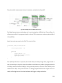
There are two main ways of designing electronic architectures for active wearable robotics: 1)
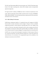
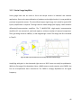
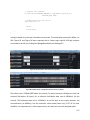
microcontroller-based and 2) embedded computer-based. Figure 1 shows a typical
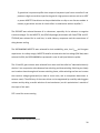
microcontroller-based architecture with a single 80MHz processor [1]. Figure 2 shows an
architecture based on an embedded computer, a Raspberry Pi running at 800MHz [2].
13
Commercial products are mostly microcontroller-based while research prototypes tend to favor
systems with embedded computers [2][11][17].
Figure 2 Embedded computer based architecture example [2]
Figure 1 Microcontroller based architecture example [1]
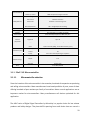
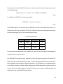
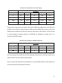
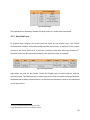
Table 1 presents a general comparison of the two design approaches.
Table 1 Architecture comparison
Microcontroller
Embedded Computer
Pros
Small form factor that can easily be adapted to
Quick design phase
different mechanical designs
High-level software (C++, Python, Java, Matlab): ease of
Low power
Unit cost is low
Low level software (C and/or ASM): processor
development
Minimize the number of specialized skills required to
modify the system
efficient
Cons
Development (prototyping) cost can be higher
Longer design phase
Requires Electrical Engineering skills for the
Higher power (less energy efficient)
design, maintenance and modification
Relies on commercial parts (no control over the
processor efficient
production and life cycle)
Low level software (C and/or ASM): less portable,
requires specialized skills
High-level software (C++, Python, Java, Matlab): not
Harder to modify
14
Integration issues between different subsystems
Sub optimal wiring
The two approaches have been used in a multitude of published wearable robotic systems, with
various degrees of success. A few examples are described here [1][2][13][17]. Since the
embedded system aspect of a design is considered a means to an end, documentation is
considered unimportant and is usually scarce. Following the evolution of a wearable robotic
design, one will read sentences such as “Developed a new embedded electronic system” without
a clear justification as to why the previous design had to be abandoned rather than improved.
In all of the designs made in the MIT Biomechatronics Group over the last 11 years, only one
project (AAKP, Agonist-Antagonist Active Knee Prosthesis [18]) used two actuators in one joint.
Due to issues with the control electronics of previous prototypes, brushed DC motors (in lieu of
brushless DC motors) were used, thus impacting the efficiency and mass of the prosthesis. When
experiments were conducted with trans-femoral amputees wearing an active ankle-foot and an
active knee the two joints were controlled independently, without an overarching high-level
controller. Consequently, the lack of availability of an appropriate embedded system solution
had a direct impact on the system design and performance [2][11].
After reading papers, grant reports and interviewing wearable robotic designers, the following
list of general system problems and reasons justifying new designs was compiled:
Lack of reliability
Lack of processing power, overloaded microcontroller
The original designer left the laboratory
No electrical engineer on the team
Slow communication peripherals
Can only support brushed motors
Can only support one motor
15
Commercial motor driver has to be tricked into running a special control loop, no built in
functionality
Power consumption
Size, mechanical integration issues
These problems are shared by many researchers in related fields such as humanoid robotics and
wearable computers, therefore many designers and companies have attempted to design a
unified embedded system that could be used in a broad range of projects. Commercially available
modular hardware platforms include the Microsoft .NET Gadgeteer system, “an open-source
toolkit for building small electronic devices using the .NET Micro Framework” 1 [3], the popular
Arduino and its Shields (“Shields are boards that can be plugged on top of the Arduino PCB
extending its capabilities.”2), the BeagleBone Black embedded computer with the Capes and the
Intel Edison with the Blocks3. SparkFun popularized the use of “breakout boards”, minimalist
circuit boards that simply prototyping. These products are now commonly integrated in academic
research projects [2][3][9][11]. Custom embedded system designs have been published for
wireless sensing [5], miniature mobile robots [6], and mechatronics education and teaching
[7][8]. The common goals are to minimize the number of circuit redesigns and simplify
prototyping [5].
The price to pay for modularity is often the increase of the number of circuit boards required for
an application, and the increase of inter-board connections. Wearable robotics projects have
different requirements than most pure robotics and wearable sensing projects. Safety and
reliability are major issues, especially in powered prosthetic devices. Simplifying the devices by
using a minimal number of circuit boards and by minimizing the number of interconnections
helps with safety and reliability. The number of degrees of freedom is relatively small (compared
to humanoid robotics), but the instantaneous power requirements are high [2][19]; a greater
emphasis has to be placed on power electronics than on digital communication between the
1
http://www.netmf.com/gadgeteer/
http://www.arduino.cc/en/Main/ArduinoShields
3
Shields, Capes and Blocks are different name for the same product category: stackable expansion boards.
2
16
modules. The volume and the weight of the embedded system must be minimized because of
their direct impact on the efficiency of devices attached to body extremities [19].
This thesis presents the design of a modular embedded system optimized for wearable robotic
applications. A flexible architecture allows FlexSEA to be used in a wide variety of projects, with
or without an embedded computer. All the safety features of commercial devices are included
onboard, as well as all the typical sensors and output device interfaces required for wearable
robotic applications. The highly integrated circuit board designs presented in the thesis minimize
the weight of the embedded system, require a minimal amount of wired connections, and are
proven to be easy to use by students. The design was evaluated by a user test and by multiple
quantifiable metrics related to the electrical performance of the different circuit board, and of
the system as a whole.
17
2 System Design
2.1 Combining architectures
The main trade-off between microcontroller and embedded computer based systems is ease of
development versus optimal design. A company designing a new product will likely opt for the
microcontroller-based system to allow a tight integration with the mechanical and industrial
design of the device while keeping unit cost at a minimum. A research lab will likely opt for the
embedded computer system to allow students and researchers without advanced electrical
engineering skills to develop and test new control schemes and wearable robot concepts [11].
One important limitation of both systems is the presence of a single computing element
(excluding the microcontrollers that are present in some sensors and motor drivers) to manage
all the sensors and actuators. Changing a high-level gate control algorithm has the potential to
introduce bugs in safety-critical motor control functions. Embedded programmers know how
easily one can break poorly written code functionality simply by adding one line at the wrong
location, breaking the precise flow of the program. A public example of a safety critical software
bug is the unintended acceleration problem of Toyota cars4. For sure, well written code should
prevent safety issues, but it’s not always what researchers have access to. This brings us to a core
idea of the flexible and scalable electronics architecture (FlexSEA): hardware and software
encapsulation.
In object-oriented programming, encapsulation refers to a language mechanism for restricting
access to some of the object's components. The programmer determines what needs to be
accessible from the outside and what should be kept private. It’s possible to build an electronic
architecture with the same principle used both for hardware and software. One example is
NASA’s Robonaut system: “Modularity is prevalent throughout the hardware and software along
with innovative and layered approaches for sensing and control.”[15]
4
http://www.edn.com/design/automotive/4423428/Toyota-s-killer-firmware--Bad-design-and-its-consequences
18
2.2 FlexSEA: core ideas and principles
The perfect architecture should:
Combine the power of efficient low-level code and the flexibility of high-level languages
Allow for quick prototyping of new prostheses and exoskeletons, both on the hardware
and the software side
Allow quick modifications and additions of sensors and actuators
Be scalable
Prevent errors on the high level code to cause safety issues
Be useable both on research prototypes and on early production units
Minimize and simplify wiring
Have built-in safety features
2.3 Subsystems
These specifications can be obtained by using one or many microcontrollers and an embedded
computer in the same system, with a clear boundary between their tasks and functions. The
embedded computer is used only for one task: high-level controls, such as finite state machines
or continuous control laws. One powerful microcontroller per axis is used to interface with all of
the sensors and simple output devices. A separate printed-circuit board assembly (PCBA)
interfaces with the electronics required for motion control.
Following a business organization naming strategy, the three FlexSEA boards are named Plan,
Manage and Execute.
19
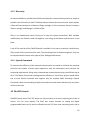
2.3.1 FlexSEA-Plan
FlexSEA-Plan is an embedded computer used for high-level computing. It boasts a powerful
processor and can run an operating system such as Linux. Developing code on this platform is
similar to the regular (i.e. non-embedded) software development process. High-level languages
such as Python can be used, saving experimental data is as simple as writing to a text file and
interacting with the system can be done via USB or WiFi. FlexSEA-Plan should be used when ease
of development is important, and when complex algorithms and control schemes require
significant computing power.
2.3.2 FlexSEA-Manage
FlexSEA-Manage is used for mid-level computing tasks. It serves as an interface between FlexSEAPlan and FlexSEA-Execute: communication protocols translation, data routing, time-sharing. It
has an Expansion connector that can interface with a wide variety of input and output devices.
Data acquisition, processing, and aggregation can be done on this board, thus unloading FlexSEAPlan from these simple tasks. For applications that do not require intensive computing, FlexSEAPlan can be taken out of the system and FlexSEA-Manage can host the high-level state machines.
2.3.3 FlexSEA-Execute
FlexSEA-Execute is an advanced brushless motor driver. Wearable robotics applications require
different control loops than the typical position and current controllers found on commercial
drives. FlexSEA-Execute has onboard sensors (6-axis IMU, temperature, voltage, current),
interfaces (strain gauge amplifier), processing power and connectivity to make it possible to close
most control loops onboard. It is well suited for the series elastic actuators (SEA) [10] commonly
used in prostheses.
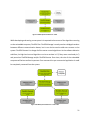
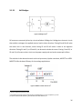
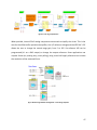
2.4 System Architecture
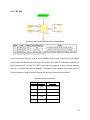
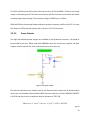
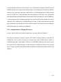
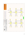
Figure 3 presents the simplest full-stack (all three FlexSEA boards) design, typical of what can be
used for a one degree of freedom (DOF) research project such as a powered knee.
20
Figure 3 FlexSEA System Architecture: 1 DOF
While developing and testing a new system it is expected to have most of the algorithms running
on the embedded computer, FlexSEA-Plan. FlexSEA-Manage is mostly used as a bridge/translator
between different communication busses, but it can also be used to add extra sensors to the
system. FlexSEA-Execute is in charge of all the motor control algorithms. As the software behavior
stabilizes, the high-level control algorithms can be re-written in C (if they were not already in C)
and ported on FlexSEA-Manage and/or FlexSEA-Execute. Over time, the role of the embedded
computer will be less and less important. On a commercial or pre-commercial application it could
be completely removed from the system.
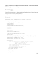
Figure 4 FlexSEA System Architecture: 1 axis 2 DOF
21
2.5 System-wide technical decisions
The main goal of that thesis is to provide researchers, at the completion of this project, with a
set of electronics boards that can be used to quickly prototype new prostheses and exoskeleton
ideas. The broad range of applications, user’s technical abilities (from neuroscientists to
mechanical engineers), and the diversity of actuators and sensors used in Biomechatronics makes
it impossible to simultaneously optimize every aspect of the system. All the constituents of the
design were selected and/or designed with modularity in mind to pave the way for future
improvements. More energy was invested in the hardware design than in the software design
because typical users are more likely to improve the software than design new boards. Over the
life of the system, it is expected that the software will be optimized, thus making FlexSEA better
over time.
2.5.1 FlexSEA-Plan: Embedded computer
The initial plan was to design a custom embedded computer with only the features required for
our application. To start experimenting before designing, the BeagleBone Black was selected. It
is economical ($55), widely available, open-source hardware (with full documentation available)
and its processor, the TI AM3358, has two Programmable Realtime Units (PRU) that can be used
to efficiently communicate with peripherals, making it a perfect reference for a custom design.
By removing multimedia features and optimizing connectors its size (89 x 55 x 15.4mm) can be
greatly reduced.
While the design efforts were focused on FlexSEA-Manage and FlexSEA-Execute, the Internet of
Things (IoT) wave grew stronger. Smaller embedded computers were released, with price tags
low enough to be embedded in typical appliances. One example is the Intel Edison. At 35 x 25 x
4mm it has a 500MHz processor, 1GB of RAM, 4GB of FLASH, Bluetooth and WiFi. It was decided
not to design a custom embedded computer but to rather use a standard communication
interface (SPI) that would allow the user to select any product on the market. Processing power
can easily be added to the FlexSEA system as new embedded computers become available.
22
2.5.2 Communication: hardware
FlexSEA-Plan and FlexSEA-Manage have to exchange information. While embedded computers
offer a lot of processing power, communication isn’t always optimal. On one hand, some of them
have simple interfaces such as serial (UART) and I²C that could be used to directly interface with
sensors and microcontrollers, but the data rates are limited. At the other extreme, the Ethernet
port can be used but it requires substantial hardware and software overhead on the FlexSEAManage board. SPI offers a communication compromise, with typical data rates above 20
Mbits/s, more than enough for our application. Due to data rate dropping quickly with distance,
FlexSEA-Manage has to be physically close to Plan.
For the interface between FlexSEA-Manage and FlexSEA-Execute(s) the common choices in
robotics are CAN [12] and EtherCAT. While CAN is cheap, robust and safe, its 1Mbps bandwidth
is an important bottleneck for application with multiple motor drivers. EtherCAT offers 100Mbps
but that speed comes with a price; the bus requires a Master. When this project was started, no
embedded computer was certified as an EtherCAT master, thus requiring the presence of a large
computer in the network. The cables, connectors and special ASICs required for EtherCAT add to
the cost, volume and complexity of the system. With the relatively small number of nodes on a
typical Biomechatronics project (less than 8) a simpler and slower interface can be used. RS-485
is often associated with old technology but its simplicity, low cost, robustness and speed (in
theory up to 100Mbps, 20Mbps achievable in our application) makes it an appealing option for
FlexSEA.
2.5.3 Communication: software
A custom communication protocol was developed for this project. It is used for the Plan-Manage
interface, for the Manage-Execute interface(s) and with the onboard USB. The hardware layer
can be modified; as long as it can deliver bits from point A to point B, the system will be
transparent to the changes. To avoid conflicts and to simplify the system, the communication is
23
highly hierarchical. The Master always initiates the transfer. It can request a Read from a Slave;
Slaves will only emit after a Read request was received.
All the details are in section 4.1 Communications and networking.
2.5.4 Software
FlexSEA-Plan,
FlexSEA-Manage
and
FlexSEA-Execute
have
three
different
microcontrollers/microprocessors but they all have to communicate together. To simplify the
development, all the controllers are ARM-based, GCC is used as the compiler and a set of
common code is shared by the three software projects.
All the details are in section 4 Software Design.
2.6 Design solutions – short answers
While all the details are available further in this document, this section offers quick answers and
solutions to all the issues identified in the introduction.
Lack of reliability: The issue of reliability is addressed at the board level with good design
practice, documented unit tests and the use of safety mechanisms (such as ESD protected inputs).
At the system level, the number of connections is reduced by embedding more features in the
boards, and robust yet miniature connectors are used.
Lack of processing power, overloaded microcontroller: A dedicated microcontroller with a wide
array of sensor inputs on the motor controller (FlexSEA-Execute) offloads the other computing
units (FlexSEA-Mange and FlexSEA-Plan) from the intensive motor control functions. The
microcontrollers used are also high performance. The optional embedded computer can be used
for processor intensive applications.
24
“The original designer left” & “No electrical engineer in the team”: Documentation must be
exhaustive and accurate in order to fully enable the user. One of the graduation criteria is a user
test. The system is designed in a modular way; the least intrusive way of using FlexSEA is to use
a simple Linux terminal.
Slow communication peripherals: Closing control loops requires deterministic timings and fast
refresh rates; it places a lot of stress on the board-to-board communication interfaces. By closing
the critical control loops on FlexSEA-Execute we offload the communication interfaces. The
FlexSEA-Manage board is also used as a bridge, communicating with FlexSEA-Plan via a highspeed SPI interface and communicating with other boards and peripherals via a variety of other
communication protocols.
Can only support brushed motors: The Execute board is designed for brushless motors; it can
inherently support brushed motors.
Can only support one motor: FlexSEA has been designed with scalability in mind. With its two
serial interfaces, FlexSEA-Manage can support two FlexSEA-Execute without any bandwidth
restrictions. More than one FlexSEA-Execute can be on each bus, the total bandwidth being
divided between the boards.
Commercial motor driver has to be tricked into running a special control loop, no built in
functionality: The user has full control over the hardware and the software of the motor driver.
Any type of controller can be programmed in C and can run at high speed on the Execute board.
The Expansion connector supports a wide variety of external sensors; they can all be used in
control loops.
Power consumption: The power consumption of the embedded system can be high when an
embedded computer is used. Better energy efficiency can be obtained by using a simpler
computer; HD video peripherals, audio amplifiers and wired Ethernet connections are not
25
required in wearable robotics applications. By maximizing the use of FlexSEA-Execute and
FlexSEA-Manage, the FlexSEA-Plan computing requirements are lowered. A slower device can be
used, or it can be placed in sleep mode between actions. Eliminating FlexSEA-Plan and
programming the high-level algorithms on FlexSEA-Manage or FlexSEA-Execute can be extremely
energy efficient.
Size, mechanical integration: The Execute and Manage boards were designed to be as small and
light as possible. They have an integration level comparable to commercial products while having
accessible connectors for inputs and outputs.
26
3 Hardware design
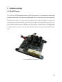
3.1 FlexSEA-Execute
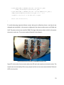
At its core, the FlexSEA-Execute board is a BLDC motor driver. It is specialized for robotic and
prosthetic applications. The high level design goals were to maximize the system integration
(small physical dimensions, large number of integrated peripherals and interfaces, support for
external input and output devices), allow fast communication and networkability via the use of a
fast multi-drop communication interface, and have built-in safety features. The design went
through three major revisions; this document focusses on the last generation (FlexSEA-Execute
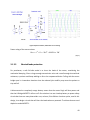
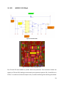
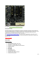
0.1).
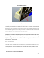
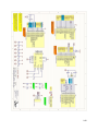
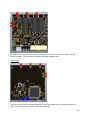
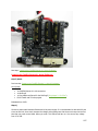
Figure 5 FlexSEA-Execute 0.1 Hardware
27
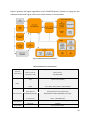
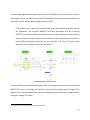
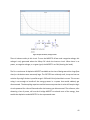
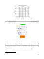
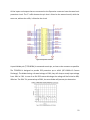
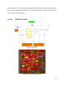
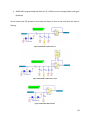
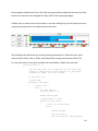
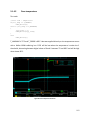
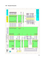
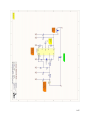
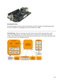
Figure 6 presents the logical organization of the FlexSEA-Execute 0.1 board. In orange are the
schematic sheets and in grey are the sub-circuits present on certain sheets.
Figure 6. FlexSEA-Execute System Diagram
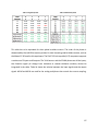
Table 2 FlexSEA-Execute 0.1 Specifications
Electrical
specifications
Motor
Microcontroller
Serial interface
Onboard USB
Supply voltage (V)
15-24V
Motor current (A)
20A Continuous
Intermediate supply
10V 500mA SMPS
Logic supply
5V 500mA SMPS
Type
3-phase brushless (BLDC)
Sensor(s)
Hall effect, optical encoder
Commutation
Block, Sinusoidal, FOC
PWM
12 bits 20kHz, 10 bits 78kHz or 9.65 bits 100kHz
Reference
PSoC 5LP - CY8C5888AXI-LP096
Special features
Programmable analog and digital blocks
CPU/RAM/IOs/Package
80MHz ARM Cortex-M3, 256KB RAM, 62 IOs, TQFP
Software / IDE
PSoC Creator 3.1, mix of C (ARM GCC 4.7.3) and graphical programming.
Co-processor(s)
PSoC 4 - CY8C4245LQI-483
Type
3x Half-Duplex RS-485 (can be full-duplex synchronous)
Bandwidth
2-10Mbps
Full-Speed (FS) 12 Mbps
28
Current sensing
Safety features
Hardware
0.005Ω resistor
Software / control
20kHz Proportional-Integral controller
Overvoltage
TVS will clamp at 36V
Overcurrent
Software protection
Locked rotor
Hardware - lead shorting circuit
Motor temperature
Hardware measurement
Board temperature
CPU + bridge temperature reading
Clutch
Strain gauge
amplifier
Variable voltage, 8-bits PWM, 400mA
Dual stage, 500 < G < 10000, high CMRR
IO connector
Molex PicoClasp 40 positions, SMD 1mm pitch
External
peripherals
Dimensions (mm)
PCB technology
IOs available
12
Digital IOs
Up to 12
Analog inputs
Up to 8 (12-bit SAR, 8-20-bits Sigma Delta)
Serial
I²C, SPI, UART
Other
1 optical encoder (A/B/I), 1 Hall effect encoder (3 pins)
X (mm)
49
Y (mm)
49
Z (mm)
From 12 to 15mm depending on capacitors
Layers
6
Copper
1 Oz
Trace/space/via
5/5 mils trace/space, 8/20 mils blind vias
Assembly
Double-sided
Other
6-axis IMU, RGB LED
3.1.1 PSoC 5 LP Microcontroller
3.1.1.1
Microcontroller selection
Since the invention of the microcontroller in the seventies, hundreds of companies are producing
and selling microcontrollers. Most manufacturers have broad portfolios of parts, some of them
offering hundreds of part numbers per family of controllers. Motor control applications are an
important market for microcontrollers. Many manufacturers sell devices optimized for this
application.
The dsPIC series of Digital Signal Controllers by Microchip is a popular choice for low volume
products and hobby designs. They have dsPICs spanning from small device that can control a
29
single motor to large chips able to drive two motors. Having designed multiple dsPIC-based BLDC
drivers for various companies before joining MIT, I decided to stay away from Microchip
products. First, I wanted to generate new IP and avoid possible conflicts. Second, I wanted to
explore outside of my area of expertise. The main problem I was facing with dsPIC-based designs
is the limited analog integration. Adding hardware safety features such as current control and
protection requires many external ICs and large surface area (or inefficient software). Power
consumption is also an issue as the dsPICs are power hungry controllers (1.9mA/DMIPS vs
228µA/DMIPS for PSoC 5 and 414µA/DMIPS for STM32F4).
TI DSPs are commonly used for advanced motion controllers, one example being the DLR Joint
[14]. The lack of either an open-source or a free closed-source development environment
prevented me from prototyping with their devices. STMicroelectronics is aggressively marketing
some of its STM32 ARM-based MCU for motor control applications. Looking at their datasheet,
they use the same design blocks as the whole industry, therefore no real technical gain could be
had.
FPGA/CPLD can offer high performance but at the cost of complexity [13], power and minimal
analog integration. One family of mixed signal microcontrollers, the Cypress programmable
system on chips (PSoC) offers a hybrid solution between an FPAA, a microcontroller and
FPGA/CPLD.
30
3.1.1.2
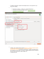
Programmable System on Chip (PSoC)
Figure 7 PSoC 5 ad - excellent visualization
Figure 8 PSoC Families5
5
http://en.wikipedia.org/wiki/PSoC
31
The PSoC 4 and 5 have modern ARM-Cortex microcontroller cores. The PSoC 5 family was chosen
because of the higher computing power, onboard USB and higher number of programmable
digital and analog blocks.
The highest end PSoC 5 subfamily, CY8C5888, was chosen to maximize the performance of the
system. While the table above mentions 67MHz, the device used in this project, CY8C5888AXILP096 is 80MHz 100DMIPS. The hybrid hardware/software implementation will be described in
the Software section of this document.
3.1.2 PSoC 4 Safety Co-Processor
FlexSEA being a development platform, it is expected that users will reprogram the FlexSEAExecute board to add new commands or control strategies. Timings are critical in embedded
programming, especially in systems without an operating system such as ours. Adding a long
routine in an interrupt, using complex floating-point math or poorly managing communication
with peripherals can disrupt the code execution; significant delays can be added, control loops
can be rendered unstable. Running the debugger (or reprogramming the microcontroller) while
the BLDC motor is turning can also have dangerous consequences. To add one layer of safety we
use a second microcontroller, the Safety-Coprocessor (Safety-CoP). A small PSoC 4 device was
selected because of the convenience of its programmable logic and the availability of the
development tools (same as for the PSoC 5).
32
Figure 9 FlexSEA-Execute hardware safety features diagram
The two PSoC are linked via an I2C bus (same bus that is used for the IMU and the digital
potentiometers) and via a Watchdog Clock line. The master PSoC, the 5LP, toggles that line in its
main loop. The safety microcontroller use programmable hardware to measure the pulse-width
and determine if the main microcontroller is behaving normally (ie if the timings are respected).
I2C is used to share sensor data, not for safety critical functions. Multiple sensors are read by the
Safety-CoP to evaluate the system state.
All the PWM lines are going through the safety coprocessor. If a problematic situation (code not
executing properly, over-temperature, disconnected battery, etc.) is detected, the safety
coprocessor can open all the signals and place the motor in a free-wheeling mode. More
elaborate protection software will then assess the situation and put the system in a safe mode
(such as a highly damped system (shorted-leads protection)).
33
Figure 10 PWM signals passing through the Safety-CoP
The Safety-CoP is also in charge of the negative voltage generation and the gate driving for the
shorted lead protection (see 3.1.3.3). More details about the safety features are available in
section 5.1.4 Safety Features.
3.1.3 Brushless DC Motor
The BLDC schematic consists of 3 copies of the Half-bridge sheet (motor commutation), the
Shorted-Leads protection circuit, phase voltage sensing and bridge temperature sensing.
Figure 11 BLDC schematic - top level
34
Figure 12 BLDC sensors (phase voltage & temperature)
U7 is routed close to the power MOSFETs. Figure 13 shows the decoupling capacitors present on
the Power Supply schematic sheet. They are mainly used for the BLDC driver. C11-14 & C22-27
are relatively small ceramic capacitors. Their total value, 100µF, is not sufficient to guarantee that
the bus voltage won’t exceed the limits if a large amount of regeneration is done. C5 to C7 are
used to absorb all this energy (and to provide power during switching transitions as well), but
they are bulky. In applications were volume is highly constrained, C5-7 can be removed if an
external protection circuit is added to the system (typically, a bus-dump semiconductor or
resistor). This should be done with care.
Figure 13 +VB Decoupling capacitors
35
3.1.3.1
Half-bridges
Figure 14 H-Bridge circuit6
DC motors are commonly driven by a circuit called an H-Bridge. An H bridge is an electronic circuit
that enables a voltage to be applied across a load in either direction. Closing S1 and S4 will make
the motor turn in one direction, while closing S2 and S3 will make it rotate in the opposite
direction. Closing S1 and S3, or S2 and S4, can be used to brake the motor. Closing S1 and S2, or
S3 and S4, will create a short circuit on the power supply and can lead to catastrophic failure.
The switches in the above schematic can be relay contacts, bipolar transistors, MOSFETs or IGBTs.
MOSFETs offer the best efficiency for low-voltage applications.
Figure 15 MOSFET vs IGBT: when to use7
6 http://en.wikipedia.org/wiki/H_bridge
7 http://www.renesasinteractive.com/file.php/1/CoursePDFs/DevCon_On-the-road/DevCon_On-the-
Road/Power/IGBT%20vs%20MOSFET_Which%20Device%20to%20Select.pdf
36
For low-voltage high-frequency application such as ours MOSFETs are the most common solution.
A good reason not to use IGBTs is that a distributor like Digikey doesn't carry devices rated for less
than 300V, and the smallest SMT package available is DPAK.
“The selection of a P-channel or N-channel load switch depends on the specific needs of
the application. The N-channel MOSFET has several advantages over the P-channel
MOSFET. For example, the N-channel majority carriers (electrons) have a higher mobility
than the P-channel majority carriers (holes). Because of this, the N-channel transistor has
lower RDS(on) and gate capacitance for the same die area. Thus, for high current
applications the N-channel transistor is preferred.”8
Figure 16 Half-bridge on Execute (1 of 3)
A voltage of 10V from the Gate to the Source (noted VGS) is required to fully turn on an N-Channel
MOSFET. The source of the high side switch can swing from the lowest system voltage to the
highest. To turn the high-side switch on we need a voltage higher than the motor voltage, typically
the highest voltage in a system.
8
http://www.onsemi.com/pub_link/Collateral/AND9093-D.PDF
37
“A gate driver is a power amplifier that accepts a low-power input from a controller IC and
produces a high-current drive input for the gate of a high-power transistor such as an IGBT
or power MOSFET. Gate drivers can be provided either on-chip or as a discrete module. In
essence, a gate driver consists of a level shifter in combination with an amplifier.”9
The IRS21867 was selected because of its robustness, especially for its tolerance to negative
transient voltages. For the MOSFETs, the QFN 5x6 package (also known as 8-PowerTDFN and PGTDSON-8) was selected for its small size, its wide industry acceptance and the convenience of
doing bottom cooling.
The BSC014N06NS MOSFETs were selected for their availability, price, low RDSON and low gate
capacitance. As a safety margin, MOSFETs rated for at least twice the bus voltage (28V Max) were
selected. At 60V, the BSC014N06NS are protected in case of really bad inductive spikes.
The R1 and R2 gate resistors were selected from what could be called an “educated arbitrarily
decision” as a compromise value between fast switching and slow switching. Switching too slowly
can introduce shoot-through and increase switching losses, while switching too fast can increase
the transient voltages generated (can lead to more noise, and to component destruction in
extreme cases). The efficiency of the motor driver can be augmented by carefully selecting gate
resistors and by doing a careful selection of semiconductors, but this optimization is outside of
the scope of this work.
R27 is used for current sensing.
9
http://en.wikipedia.org/wiki/Gate_driver
38
Figure 17 The 3 channels use the same compact layout (B highlighted)
As can be seen on Figure 17 a large number of vias are used. They serve two purposes: thermal
transfer and layer “tying”. This PCB has 6 layers:
Layer 1: Top components, signals and small planes
Layers 2 and 5: Ground planes
Layer 3: Power. Top half is a +VB plane, Bottom half is a +5V plane.
Layer 4: Mixed. In the context of the bridges, it is used for the MOT nets and for +VB.
Layer 6: Bottom components, interface to the heat sink (so a maximum plane area is used
around the bridges).
The critical power paths are always shared by a minimum of two layers.
3.1.3.2
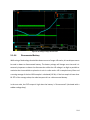
Motor current sensing
The programmable analog blocks of the PSoC can be used to design a small, low-cost motor
current sensor. One shunt resistor per bridge is used. Two resistors and one capacitor are
required for the feedback. In the PSoC we use one operational amplifier, one DAC and one analog
multiplexer.
39
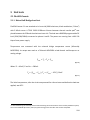
Figure 18 Spice simulation, ±20A motor current sensing
Power rating of the sense resistor:
𝑃𝑅𝐸𝑆 = 𝐼 2 ∗ 𝑅 = 20𝐴2 ∗ 0.005Ω = 2𝑊
(Eq 1)
3.1.3.3
Shorted-leads protection
For prostheses, a safe fail-safe mode is to short the leads of the motor, maximizing the
mechanical damping. Given a large enough transmission ratio and a small enough shorted lead
resistance, a patient could keep walking on his or her unpowered device. Failing with the motor
bridge open is a hazardous situation since the reduced joint stability may cause the patient to
trip and fall.
A disconnected or completely empty battery means that the control logic will lose power and
that the H-Bridge MOSFETs will turn-off. One solution is to use a backup battery to power safety
circuits but there are many downsides: cost, volume, finite lifetime. Another option, used in this
design, is to design a circuit that will short the leads when un-powered. To achieve that we used
depletion mode MOSFETs.
40
Figure 19 Shorted-leads protection implemented with depletion mode MOSFETs
Figure 20 Shorted-leads protection: negative voltage generation and gate control
41
Figure 21 Spice simulation, voltage inverter
There is inherent safety in this circuit. To turn the MOSFETs off we need a negative voltage; this
voltage is only generated when the Safety-CoP clocks the inverter circuit. When there is no
power, no negative voltage, or no gate signal, the MOSFETs are ON (shorting the leads).
The RDS-ON resistance of depletion MOSFETs available at the time of design was either large (few
ohms) or the devices were extremely large. The CPC3703 are relatively small, cheap and not too
resistive. By using 3 devices in parallel we get 1.33Ω and 1.8A of pulsed drain current. This current
rating is not enough to handle all the energy present in a system that would suddenly get
disconnected. The decoupling capacitors and the brownout protection circuits will keep the logic
circuits powered for a few milliseconds after the battery gets disconnected. The software, after
detecting a loss of power, will use the h-bridge MOSFETs to absorb most of the energy, then
enable the depletion mode MOSFETs for the unpowered state.
42
3.1.4 RS-485
Figure 22 One of the 3 RS-485 transceivers present on FlexSEA-Execute
Figure 23 RS-485 Modes: synchronous/asynchronous, half- or full-duplex
Three transceivers allow the user to select between three modes: asynchronous half duplex,
asynchronous full-duplex and synchronous full-duplex. The trade-off is between simplicity and
data transfer speed. The PSoC 5LP UART module can be configured for 8x or 16x oversampling
and has a maximum baud rate of 4Mbits/s. The Master Clock is 80MHz and we can only use
fractional dividers. Using 8x we can calculate the baud rate versus the clock divider:
Table 3 Baud rate versus clock divider
Divider Baud rate
Comment
1
10M
Over 4M, invalid
2
5M
Over 4M, invalid
3
3.33M
4
2.5M
5
2M
43
The baud rate selected on FlexSEA-Execute has to be closely matched with the baud rate selected
on FlexSEA-Manage:
𝑏𝑎𝑢𝑑𝑟𝑎𝑡𝑒𝑀𝑎𝑛𝑎𝑔𝑒 = 𝑓𝐶𝐿𝐾 ⁄(8 ∗ (2 − 𝑂𝑉𝐸𝑅8) ∗ 𝑈𝑆𝐴𝑅𝑇𝐷𝐼𝑉)
(Eq 2)
fclk is 84MHz and OVER8 is 0 for 16x oversampling.
𝑈𝑆𝐴𝑅𝑇𝐷𝐼𝑉 = 𝑓𝐶𝐿𝐾 ⁄16 ∗ 𝑏𝑎𝑢𝑑𝑟𝑎𝑡𝑒
(Eq 3)
In the STM32 register, the fractional part of USARTDIV is stored in 3 bits (8 possible values). The
fractional part has to be a multiple of 1/8 (0.125). Different values have to be approximated, thus
introducing averaging errors in the communication timings.
Table 4 Error versus baud rate
Baud rate USARTDIV Rounding error Error (%)
2M
2.625
0
0
2.5M
2.100
0.025
1.19
3.33M
1.575
0.050
3.17
To minimize the communication errors 2Mbits/s is used. That limit can easily be overpassed by
using synchronous communication.
The SN65HVD75 transceivers were selected for their high tolerance against ESD events (IEC
12kV), small size and wide availability. No dual- or triple-transceivers offered the same protection
level; integration was sacrificed to increase robustness. The 8-TSSOP was only selected because
of a bad filter selection on Digikey. While designing the FlexSEA-Manage 0.1 board it was found
out that a 3x3 mm 8-SON package is available. The latter one is used on FlexSEA-Manage, and
will be used in the next FlexSEA-Execute revision.
44
3.1.5 Strain Gauge Amplifier
Strain gauge load cells are used as force and torque sensors in industrial and research
applications. Due to the commoditization of products such as digital scales it is now possible to
purchase inexpensive sensors. The sub-millivolt output signal range isn’t suited for typical ADC
inputs; amplification is required. The large common mode voltage (half-supply) is well suited for
differential/instrumentation amplifiers. The TI INA331/2331 single-supply instrumentation
amplifiers ICs are economical, small and require a minimum number of external components.
Their gain being limited to 1000V/V, a dual stage design is used. The design was first simulated
in TINA-TI.
Figure 24 TINA-TI Spice simulation of the two stage differential amplifier design
Amplifying with gains in the thousands right next to a BLDC motor can easily be problematic.
While the first page of the datasheet claims a 94dB common-mode rejection ratio (CMRR), the
first set of experiments were inconclusive. The CMRR is strongly dependent on the signal
frequency:
45
Figure 25 CMRR vs Frequency, TI INA331/233110 instrumentation amplifier
Typical motor PWM frequencies are from 20 to 100kHz. Analog filtering was added before the
first amplification stage, limiting the bandwidth to 500Hz and offering 44dB of rejection at 20kHz.
Figure 26 Input: filtering and protection
Two I2C digital potentiometers (Microchip MCP4661, dual potentiometer, U5) are used to adjust
the offset and the second stage gain. U5B allows the user to adjust the output reference of the
first stage by ±20% (centered at half supply). The offset adjustment span of ±20% and the fixed
gain of 105 were calculated based on experimental data (5 load cells were randomly selected and
measured. The worst offset was used to calculate the required compensation.)
10
http://www.ti.com/lit/ds/symlink/ina331.pdf
46
Figure 27 Two stage amplification
When possible, internal PSoC analog components were used to simplify the circuit. This is the
case for the offset buffer operational amplifier, the V/2 reference voltage and the VR2 DAC. U5C
allows the user to change the second stage gain, from 5 to 105. Via software VR2 can be
programmed (it’s on a DAC output) to change the output reference. Some applications use
unipolar forces (ex. pushing only, never pulling); using a non-half-supply reference can increase
the resolution of the measured force.
Figure 28 PSoC Programmable Analog Blocks - Strain Gauge Amplifier
47
3.1.6 Clutch
Figure 29 Clutch driver schematic
Locking the position of a motorized joint requires power, even when there is no motion. This is
an inefficient use of energy [2]. Designs such as the CSEA Knee use an electro-magnetic clutch to
hold a joint in place without requiring power from the motor [2].
When not engaged, the air gap between the two pieces of the clutch reduces the attraction force
of any magnetic field that the clutch can generate. More current is required to engage the clutch
than is necessary to keep it locked. Using PWM, it is possible to use maximum power to engage
the clutch, then reduce the voltage applied across its terminal as an energy saving feature.
Use of a high-side switch is preferred because it is typical to link the metal chassis of prostheses
to ground and some clutches have their casing grounded. Using a high-side switch can simplify
the electromechanical integration. The power requirements being low, it is possible to use a PChannel MOSFET as a switch. D13 is used as a free-wheeling diode for inductive loads, as a
protection for Q3.
48
3.1.6.1
P-MOSFET power dissipation
The clutched used in the experimental setup and in the CSEA Knee is rated for 24V 250mA 6W.
The unit in hand was tested at 242mA. To accommodate bigger clutches (and other output
devices) the calculations will be done for 24V 10W (417mA), used at 10V. The current at 10V will
be 174mA.
Using an FDN5618P P-MOSFET:
𝑃𝐷𝑅𝐸𝑆𝐼𝑆𝑇𝐼𝑉𝐸 = [𝐼𝐿𝑂𝐴𝐷 2 ∗ 𝑅𝐷𝑆(𝑂𝑁) ] ∗ (𝑉𝑂𝑈𝑇 ⁄𝑉𝐼𝑁 )
11
(Eq 4)
𝑃𝐷𝑆𝑊𝐼𝑇𝐶𝐻𝐼𝑁𝐺 = [𝐶𝑅𝑆𝑆 ∗ 𝑉𝐼𝑁 2 ∗ 𝑓𝑆𝑊 ∗ 𝐼𝐿𝑂𝐴𝐷 ]/𝐼𝐺𝐴𝑇𝐸
(Eq 5)
Where:
ILOAD: 174mA
VOUT/VIN = D = 10V/24V = 0.42
RDS(ON) = 0.315 Ω (worst case)
CRSS: 19pF
VIN: 24V
fSW: 20kHz
Igate: 10.9mA
We obtain 𝑃𝐷𝑅𝐸𝑆𝐼𝑆𝑇𝐼𝑉𝐸 = 4𝑚𝑊 & 𝑃𝐷𝑆𝑊𝐼𝑇𝐶𝐻𝐼𝑁𝐺 = 3.49𝑚𝑊 . The total power dissipation is
7.5mW. If the clutch is powered at 24V 10W (no switching) the dissipation will be 55mW. The
thermal resistance of the SuperSOT-3 package, from junction to ambient, is 270°C/W.
𝑇𝐽 = 𝑅𝐽𝐴 ∗ 𝑃 + 𝑇𝐴 = 270˚
𝐶
∗ 55𝑚𝑊 + 35˚𝐶 = 49˚𝐶
𝑊
(Eq 6)
11
Based on http://electronicdesign.com/boards/calculate-dissipation-mosfets-high-power-supplies
49
3.1.6.2
Level shifting
A pre-biased NPN BJT (RN1106MF) and two resistors are used to allow one 0-5V microcontroller
output to turn on and off the P-MOSFET. The battery voltage can span from 15 to 28V. V GS is
determined by the ratio of R32 and R33 and by the saturation voltage (VCE_SAT) of the BJT (0.3V
max). VCE_SAT being less than 2% of the minimum voltage it is negligible.
𝑉𝐺𝑆 = 𝑉𝐵 (1 − (𝑅33 /(𝑅33 + 𝑅32 ))) = 0.5𝑉𝐵
(Eq 7)
VB ranging from 15 to 28V, VGS will be from 7.5 to 14V, below the maximum of ±20V and high
enough to provide a low RDSON.
3.1.7 IMU
Accelerometer and gyroscope are commonly used for the control system of prostheses and
exoskeleton. They are used to measure angular velocities, angles and impacts. The MIT CSEA
Knee [2] used a sensor board12 populated with an ADXL345 accelerometer (3-axis, ±2 to ±16g)
and an ITG-3200 gyroscope (3 axis, ±2000°/s) [2][11]. The MIT Autonomous Exoskeleton [19] uses
a LPY550ALTR dual-axis gyroscope (500 °/s). These parts were selected because their range
covers the angular velocities and accelerations of human walking.
For the FlexSEA-Execute board a single chip solution is used. The MPU-6500 integrates a 3-axis
accelerometer (±2 to ±16g), a 3-axis gyroscope (±250 to ±2000°/s) and a temperature sensor. The
same IMU is present on the FlexSEA-Manage board. An example application that would require
IMUs on both the FlexSEA-Manage and the FlexSEA-Execute boards is a dual leg exoskeleton with
waist mounted control electronics. The Execute boards would be located on the feet while
12
https://www.sparkfun.com/products/10121
50
FlexSEA-Manage’s IMU can record whole body motion and user intent (such as sitting, leaning,
etc.)
Figure 30 IMU schematic
The main limitation that was found during software development was the low frequency of the
I2C bus, 400kHz. All the devices from the same manufacturer have the same limitation,
preventing an easy modification. Information can be accessed faster via SPI.
The IMUINT signal can be used to time the data acquisitions with the availability of new
measurements.
3.1.8 IO Protections
Figure 31 External I/O protection circuit
51
All the inputs and outputs that are connected to the Expansion connector have the same basic
protection circuit. The ‘E’ suffix denotes the pin that is linked to the external world, while the
same net, without the suffix, is linked to the circuit.
Figure 32 Expansion connector
A special diode pair (TI TPD4E004) is connected to each pin, as close to the connector as possible.
The TPD4E004 is designed to provide ESD protection up to ±8-kV (IEC 61000-4-2 Contact
Discharge). The diodes having a forward voltage of 0.8V, they will clamp a steady input voltage
from -0.8V to 5.8V. In case of an 8kV ESD contact discharge the voltage will be limited to 80V,
100x less. The PSoC 5 is protected up to 500V; the extra diodes will prevent pin destruction.
52
Figure 33 TPD4E004 ESD Clamping13
Figure 34 ESD diode routed right under the Expansion connector
A series 100 ohm resistor limits the current to (5-0)/100 = 50mA in case a high output is shorted
to ground. The same series resistor will also limit the current when the diodes are clamping the
input voltage. The maximum rating for PSoC 5 pins is 41mA. A resistor of 120 ohm should be used
instead of 100 ohm. This is reflected in the Future Work section.
A higher degree of protection would be gained from using a higher value resistor. The main tradeoff of designing a system that can be used for any situation is that one cannot optimize every
single detail. Using a value such as 1k or 10k for un-buffered analog inputs would introduce too
much noise in the ADC conversion.
3.1.9 User interface
A RGB LED is used to display the state of the code (normal, communication loss, warning, error).
A flashing green LED is used as a heartbeat signal: when the code is running properly it flashes.
13
http://www.ti.com/lit/ds/symlink/tpd4e004.pdf
53
Figure 35 RGB LED and Green "heartbeat" LED
The white balance of the RGB LED is poor due to a bad assumption (constant current across colors
does not lead to white light when R, G & B are turned fully ON). The Future Work section specifies
different resistor values. A USB port is present on board for debugging. Users can use it to send
FlexSEA commands to Execute without the need of Manage and/or Plan.
Figure 36 USB ESD protection
Figure 37 USB protection routing
54
3.1.10
Power Supplies
4 different voltages are required on Execute. Table 5 specifies the naming convention and the
voltage ranges.
Figure 38 Power Supplies Schematic
Table 5 Power Supplies
Symbol
+VB
Voltage
Source
Details
15-28V (typ. 24V) Battery
Battery voltage
+VG
10V
+VB
Gate driver voltage, input for low voltage regulators
+5V
5V
+VG
Logic supply - almost everything
+3V3
3.3V
+5V
Logic supply, RS-485 & IMU
3.1.10.1
Brown-out protections
When turned-on, inductive loads such as motors will draw a current that is only limited by their
equivalent series resistance. This current can be extremely high because the resistance is kept to
a minimum to limit thermal losses. During such events it is important to keep the control
electronics powered. To prevent those currents from stealing energy from the logic power
supplies we use a simple circuit consisting of a diode and a capacitor.
55
Figure 39 Brownout protection
+Vin is the input voltage that would normally go to the next circuit. Instead, the diode prevents
the input filter capacitor from being discharged by anything else than the current on +Vout. The
capacitor can be sized to provide a sufficient energy reserve to keep the output voltage regulated
when the bus voltage drops.
The diode decreases the efficiency of the power supply. Using a Schottky with a small voltage
drops keep the losses to a minimum. Efficiency loss for a theoretical circuit that converts from 24
to 12V with 100% efficiency, with a 500mA load on its output (6W):
𝑉𝐼𝑁 = 24𝑉 − 𝑉𝐷𝑅𝑂𝑃 = 24𝑉 − 0.5𝑉 = 23.5𝑉
(Eq 8)
𝐼𝐼𝑁 = 𝑃𝑂𝑈𝑇 ⁄𝑉𝐼𝑁 = 6𝑊 ⁄23.5𝑉 = 255.32𝑚𝐴
(Eq 9)
𝑃𝐼𝑁 = 𝑉𝐼𝑁 ∗ 𝐼𝐼𝑁 = 24𝑉 ∗ 255.32𝑚𝐴 = 6.13𝑊
(Eq 10)
𝑛 = 𝑃𝑂𝑈𝑇 ⁄𝑃𝐼𝑁 = 6𝑊 ⁄6.13𝑊 = 97.8%
(Eq 11)
3.1.10.2
Low voltage power supplies
It is important to minimize the power consumption of prostheses and other wearable robots to
minimize the volume and weight of the batteries used (they have a direct effect on system
efficiency) and to minimize heat generation, a potential cause of discomfort for the users. The
MOSFET gate drivers require 10V and the microcontroller and most sensors are powered at 5V.
56
Using a linear regulator to provide 50mA at 5V (250mW) requires 50mA at 24V (1.2W), a 21%
efficient energy conversion with almost 1 watt of heat that requires to be dissipated; this is
unacceptable. The only sensible solution is to use one or more switched-mode power supplies
(SMPS).
The current requirement on the 10V bus being small, it was decided to use the 10V as a preregulation stage for the 5V power supply. Using 10V rather than 24V as an input voltage allows a
wider range of ICs to be used.
The core of both circuits was designed with TI WEBENCH Design Center 14 . The same list of
modifications was applied to both designs, as detailed below.
14
http://www.ti.com/lsds/ti/analog/webench/overview.page?DCMP=sva_web_webdesigncntr_en&HQS=sva-webwebdesigncntr-vanity-lp-en
57
3.1.10.3
LM25011 10V 500mA
Figure 40 10V 500mA SMPS
Figure 41 Compact routing using polygon pours
D9, C38 and C39 were added to provide brown-out protection. Size constraints limited the
capacity of C38 and C39, leading to an extremely short protection period. C40, L2 and C8 form a
PI filter. It is used to minimize the output noise, to avoid transferring that switching noise down
58
to the 5V supply. F1 is a PTC (Positive Temperature Coefficient), also known as a resettable fuse.
The circuit was designed with a 650mA current limit (by selecting Rs = 0.2Ω), the PTC should only
trip in case of a catastrophic failure.
3.1.10.4
TPS62163 5V 500mA
Figure 42 5V 500mA SMPS
Figure 43 Compact routing using polygon pours
59
3.1.11
Future Work and Circuit Modifications
List of modifications that do not require circuit modifications (only BOM changes):
Lower the I²C resistor pull-ups (R45, R46) to 1.8kΩ (currently 4.7kΩ)
Change the IO protection resistors (R10-R13, R64, R65) to 120Ω (currently 100Ω)
Less resistive PTCs (F1, F2)
Lower the Gate resistor values by at least half. More calculations and testing is required
to find the optimal value.
List of modifications requiring circuit modifications:
The 400kHz I²C limit on the MPU-6500 is slowing down the bus. If a new IMU has to be
selected a 1MHz version should be considered.
RGB LED: poor color balance. The next design should use 243/249/412Ω.
Add a second green LED to unify the user interface with Manage.
Add an external filtering capacitor for the Delta Sigma converter (0.1 to 1.0µF, see
component datasheet).
Add SWD (P1[3]) to the PSoC 5 SWD connector (J9). The Serial Viewer isn’t supported
yet but will be convenient in the future.
The ‘+5V’ supply should be measured.
The RS-485 transceivers (U4, U10, U11) should use the 8-SON package to save board
space and unify the BOM with Manage.
The position of the SWD connectors (J5, J9) is not convenient. They should be on the top
side. Swapping their position with the RS-485 transceivers would be convenient.
Many expansion pins are on port 12. They are SIO and not GPIO (no analog features).
Most of the expansion signals should support analog inputs.
60
The only patch that needs to be applied to use the circuit is to lower the I²C pull-ups. All the
other changes are not problematic but will improve the quality of the design.
3.2 FlexSEA-Manage
Figure 44 FlexSEA-Manage 0.1
FlexSEA-Manage is a polyvalent circuit that can have a wide range of usages depending on the
system architecture. In the simplest system designs, it will act as a communication protocol
translator, allowing Plan and Execute to communicate. When multiple FlexSEA-Execute are used,
it routes packets, and can manage communication timings. It can be used to add extra sensors
and output devices to the system. In systems that do not require the computing power of an
embedded computer, Manage can host the high-level state machines.
Figure 45 presents the hardware diagram of FlexSEA-Manage 0.1. In orange are the schematic
sheets and in grey are the sub-circuits present on certain sheets.
61
Figure 45 Manage 0.1 Hardware
Table 6 FlexSEA-Manage 0.1 Specifications
Electrical
Supply voltage (V)
specifications
Current (mA)
90mA
Reference
STM32F427ZIT6
Special features
Floating-point co-processor can be software enabled.
CPU/RAM/IOs/Package
180MHz ARM Cortex-M4, 2MB FLASH, USB
Software / IDE
Eclipse C/C++, GNU Tools for ARM Embedded Processors (arm-none-eabi-gcc), OpenOCD GDB.
Type
2x [half-duplex, asynchronous full-duplex or synchronous full-duplex RS-485]
Bandwidth
2-10Mbps
Type
Full-duplex SPI
Bandwidth
20+ Mbps
Microcontroller
Serial interfaces
Onboard USB
5V in (from Plan or USB), on-board 3V3 regulator
Full-Speed (FS) / High-Speed (HS)
FLASH memory
128Mbits
IMU
6-axis (3x accelerometer, 3x gyroscope)
Peripherals /
Power output
2x 24V 1A high-side switches
features
LEDs
2x green, 1x RGB
Switches
1x user input switch
IO connector
Molex PicoClasp 40 positions, SMD 1mm pitch
IOs available
17, shared with functions below
External
Digital IOs
Up to 9, protected
peripherals
Analog inputs
8x 12-bit SAR with special functions (filters, amplifiers, dividers, …)
Serial
I²C, SPI, USART
Dimensions (mm)
X (mm)
40
Y (mm)
40
62
Z (mm)
PCB technology
11.5
Layers
4
Copper
1Oz
Trace/space/via
5/5 mils trace/space, 8/20 mils vias
Technology
Standard
Assembly
Double-sided
3.2.1 Microcontroller
In systems with an embedded computer, Manage is used as communication translator (between
SPI and RS-485), as a router and as a sensor processing unit. When an embedded computer isn’t
used Manage will host the high-level state machines. All these applications require fast
communication peripherals (a minimum of 1 SPI and 2 UARTs) and fast processing.
To support all the sub-circuits present on Manage we need a microcontroller with:
A minimum of 3 SPI ports (1 for Plan, 1 for the FLASH, 1 for the Expansion connector)
A minimum of 3 UARTs (2 for RS-485, 1 for the Expansion connector)
A minimum of 2 I²C ports (1 internal, 1 for the Expansion connector)
A minimum of 8 12-bits analog inputs
A minimum of 20 digital I/Os
USB
While using a microcontroller from the same family as on Execute (another PSoC) would have
simplified the development process, no PSoC had enough computing power or I/Os to fulfill all
the requirements (100DMIPS, 62 IOs 15 ). Instead, an industry standard Cortex-M4 core was
implemented to benefit from the Floating point Unit (FPU).
Many vendors license the Cortex-M4 (Texas Instruments, Atmel, Freescale, STMicroelectronics,
NXP, etc.) The STM32F4 family from STMicroelectronics was selected primarily because it has a
15
With the newly released chip-scale (BGA) package more IOs are available then at the time of this design.
63
large base of customers and part references, affordable development tools and comprehensive
public documentation.
Figure 46 STM32F4 sub-families16
The STM32F427ZI was selected because it is 180MHz and has the largest amount of memory
possible. The F437 and F4x9 chips only add TFT controllers and video accelerators that are not
required in our application.
The LQFP-144 package was the smallest package that allowed the use of all the required
peripherals.
3.2.2 Interface to Plan
Most of the work presented in this thesis was using a BeagleBone Black embedded computer as
the FlexSEA-Plan board. While the previous version of the FlexSEA-Manage board, MiddleMan
0.1, was designed to fit its form factor, the Manage 0.1 was designed with polyvalence in mind.
Multiple new embedded computers are released every year. Having the option of using new
generation hardware can extend the life of the FlexSEA system.
16
http://www.st.com/web/en/catalog/mmc/FM141/SC1169/SS1577?sc=stm32f4
64
Figure 47 MiddleMan 0.1 (predecessor to Manage 0.1) on top of a BeagleBone Black
The only specific requirement is to have a fast full-duplex SPI bus. The connector that interfaces
with Plan has 8 pins: +5V to power the circuits on Manage17, 4 wires for SPI (MOSI, MISO, SCK &
NSS), a reset signal and a +VP (Plan Voltage) line.
Figure 48 Interface to Plan
The +VP line is used with a TXB0104 voltage level translator IC to interface an embedded
computer with an IO voltage between 1.2 and 3.3V and the 3.3V Manage microcontroller.
17
The +5V can come from any power supply, it doesn’t have to be from Plan
65
Figure 49 Level translation, SPI
R72 to R80 are series termination resistors for the fast SPI lines. The output characteristics of the
Plan computer being unknown, and the cabling between FlexSEA-Plan and FlexSEA-Manage
depending on applications, it was not possible to calculate the proper terminations. The 0Ω
resistors are used as place-holders.
The external reset line is connected to the base of Q5B, another way of doing level shifting.
Figure 50 Level shifting, external reset signal
66
User code being executed on the Plan board can be stopped at any time. Some situations will
place the SPI bus in a bad state, thus requiring either special management code on the FlexSEAManage board or that it can be rebooted by FlexSEA-Plan.
3.2.3 Inputs and Outputs
J2 is a 40 pins Molex Pico-Clasp dual row, right-angle connector. It is used by users to access the
9 digital I/Os, the 8 analog inputs, two power outputs and some supplies. It also hosts 6 twistedpairs for RS-485.
Figure 51 Expansion connector
3.2.3.1
Analog Inputs with Programmable Features
8 analog inputs are available on the Expansion connector. To minimize the number of external
components required to interface with common sensors, 4 different circuits are used.
AN0 & AN1: 1 or 10kHz low-pass filter, unity gain (buffered)
AN2 & AN3: 1 or 10kHz low-pass filter, I²C programmable gain (1<G<10, 8 bits)
AN4 & AN5: unity gain (buffered)
67
AN6 & AN7: programmable pull-down (0 < R < 10kΩ) to use as a voltage divider, unity gain
(buffered)
All the inputs have ESD protection and weak pull-downs to force a low level when the input is
floating.
Figure 52 AN0 & AN1: 1/10kHz LPF, G=1
Figure 53 AN2 & AN3: 1/10kHz LPF, 1<G<10
Figure 54 AN4 & AN5: Buffered input
68
Figure 55 AN6 & AN7: Programmable voltage divider
Four I2C digital potentiometers (Microchip MCP4661, dual potentiometer, U3 & U4) are used to
adjust the gains and the voltage divider resistances. They share the same I²C bus as the IMU.
3.2.3.2
Digital Inputs & Outputs
9 digital signals are available on the Expansion connector.
Figure 56 Protected Digital IO
Table 7 Special Digital IO functions
Signals
Special function
DIOx0/1
I2C2
DIOx2/3
UART3
DIOx/4/5/6/7
SPI6
69
For DIO2 to DIO8 a series 1kΩ resistor limits the current to (3.3V-0)/1000Ω = 3.3mA in case a high
output is shorted to ground. The same series resistor will also limit the current when the diodes
are clamping the input voltage. The maximum rating for STM32 pins is ±25mA.
DIO0 and DIO1 do not have pull-downs and series resistors to prevent conflicts with I2C. For more
info about the ESD protection please refer to Section 3.1.8 IO Protections.
3.2.3.3
Power Outputs
Two high-side switched power outputs are available on the Expansion connector. +VB needs to
be provided by the user. When used with AWG#28 crimps the contacts are rated for 1A. Both
outputs are also rated for 1A; their total should not be more than 1A.
Figure 57 1 of 2 power outputs
The thermal calculations are simpler than for the Execute clutch output (see 0) because these
drivers are not intended to be used with PWM. The worst-case RDS(ON) of the FDN5618 P-MOSFET
is 0.315Ω and the junction-to-ambient thermal resistance is 270°C/W.
𝑃𝐷𝑅𝐸𝑆𝐼𝑆𝑇𝐼𝑉𝐸 = 𝐼𝐿𝑂𝐴𝐷 2 ∗ 𝑅𝐷𝑆(𝑂𝑁) = (1𝐴)2 ∗ 0.315 = 0.315𝑊
(Eq 12)
70
𝑇𝐽 = 𝑅𝐽𝐴 ∗ 𝑃 + 𝑇𝐴 = 270˚
𝐶
∗ 315𝑚𝑊 + 35˚𝐶 = 120˚𝐶
𝑊
(Eq 13)
It leaves a 30°C margin before the maximum junction temperature is reached. 270°C/W being for
the smallest pad possible, it is expected that the thermal resistance will be lower in the current
design. Upon close inspection of the layout a comment was added to the list of future
modifications; the drain should be attached to a bigger copper area. Another option is to replace
the FDN5618 by a SI2319CDS 77mΩ MOSFET (same package, 10 cents more).
3.2.4 IMU
Please refer to Section 3.2.4 IMU in FlexSEA-Execute hardware. The two designs use the same
IMU.
3.2.5 FLASH
The Manage board has an onboard FLASH memory for data logging during experiments. It can be
used for systems that do not include a Plan board.
Figure 58 FLASH Memory
71
Table 8 Bits of storage needed per second of data logging
Data bytes
Frequency (Hz)
2
4
8
16
32
1
16
32
64
128
256
10
160
320
640
1.28k
2.56k
100
1.6k
3.2k
6.4k
12.8k
25.6k
1000
16k
32k
64k
128k
256k
Typical science experiments are limited to 30 minutes (1800s) and logging rates from 100Hz [11]
to 200Hz [1] are sufficient. Saving 16 bytes at 100Hz requires 23Mbits. No memories of less than
32Mbits were considered. The main part selection criteria were 1) SPI interface, 2) small size and
3) common/industry standard package. The M25P128 has 128Mbits of storage and is in a
convenient 8-VDPFN package.
Table 9 Minutes of data logging in a 128Mbits FLASH memory
Data bytes
Frequency (Hz)
2
4
8
16
32
100
1333
667
333
167
83
1000
133
67
33
17
8
The traces between the FLASH and the STM32 being electrically short, termination should not be
required. R32 to R35 are included as placeholders.
Users can access the stored data via the USB port or via the FlexSEA network. A radio module can
also be connected to the Expansion connector.
72
3.2.6 User Interface
The same RGB LED, Green LED and USB protection circuit as on Execute are used (see 3.1.9). The
differences are: 1) the presence of a second Green LED and 2) one user button.
Figure 59 User input
Having a least one user push-button in the system is convenient for demonstrations, allowing
one to start test code and/or experiments without requiring the use of a remote computer.
73
3.2.7 RS-485
Section 3.1.4 goes over all the details
of the 3 RS-485 modes, baud rate and
transceiver selection. The differences
are: 1) the presence of 6 transceivers
on Manage, 2) the hardwired enable
signals and 3) the smaller IC packages.
By routing all the enable (DE, !RE)
signals to the PSoC, Execute could use
the three transceivers independently.
This is not the case for the Manage
board; the internal peripherals and
pin assignments made it impossible to
get the same flexibility.
USART1 and USART6 are used because
they are clocked by APB2 (84MHz)
while all the other UxARTs are clocked
by APB1 (48MHz). With a 84MHz clock
the two USARTs can achieve baud
rates up to 10.5Mbits/s.
Figure 60 RS-485 #1 3 transceivers
74
3.2.8 Power
The Manage board requires 5V. It can be provided by the Plan board (or by an external supply
connected to the Plan connector) or via the USB connector. An autoswitch power multiplexer is
used to select the power source. When +5VP (from the Plan connector) is available, it is used.
Using USB power is useful for simple tests and debugging when an external supply is not
available.
Figure 61 Autoswitch Power Mux and 3.3V LDO Regulator
A TPS73733 linear regulator is used to obtain 3.3V from +5V. As shown on the schematic note,
its junction temperature shouldn’t rise above 115°C in the absolute worst case scenario.
To test the autoswitching feature the Manage 0.1 board was powered from an external supply
and from USB. The yellow trace is +5V, the blue trace is +3V3. The external power supply was
turned off and the event was caught by the oscilloscope (triggering on a negative slope at 4.75V).
75
3.2.9 Future Work and Circuit Modifications
List of modifications for the next hardware revision:
When hot-plugged the STM32 doesn’t not always properly power on. Evaluate the use
of a power sequencer.
The 2 power outputs have tiny dissipation pads. Increase copper area on the drain
connection or select a MOSFET with a lower Drain to Source resistance.
The 400kHz I²C limit on the MPU-6500 is slowing down the bus. If a new IMU has to be
selected a 1MHz version should be considered.
RGB LED: poor color balance. The next design should use 243/249/412Ω.
76
4 Software Design
While the focus of this thesis was system and hardware design, a large amount of embedded
software had to be written to enable all the functionality of the FlexSEA system. The
communication stack, shared by all the boards, required 5153 lines of C code. 12030 lines of code
are specific to the sub projects (motor control, terminal interface, signal processing, etc.), for a
grand total of 17183 lines of C. This section will take a high-level approach to describe the
software design of FlexSEA rather than diving down in the details. Readers will get an overall
understanding of the organization; the modularity of the software and the abundance of
comments, combined with this document, should provide anyone with enough information to
use and modify the system.
4.1 Communications and networking
A communication protocol is a system of digital rules for data exchange within or between
computers and embedded devices. At the highest level, “intelligent” information is exchanged,
such as “set motor pwm duty cycle to 100%”. On the lowest level (hardware level) it’s always an
exchange of electrons or photons. The span between these two extremes is divided is layers. The
Open Systems Interconnection model (OSI) is composed of 7 layers.
Figure 62 OSI model18
18
http://en.wikipedia.org/wiki/OSI_model
77
While the OSI model can represent systems as complex as Internet, for embedded applications it
is possible to simplify by merging layers 4 through 7 into a single Application layer. With a limited
need for packet routing, layer 3 (Network) is absorbed by layer 2 (Data link).
4.1.1 Application Layer
At the highest abstraction level, intelligent information is exchanged between different FlexSEA
boards without any regards for the physical media used. The list of commands available to the
user is presented in Table 10.
Table 10 List of FlexSEA Commands
Command
ping
status
reset
ack
mem
acqui
rs485_config
usb_config
usb_write
temp
switch
imu
encoder
strain
strain_config
volt
batt
power_out
clutch
adv_ana_config
analog
digital
digital_config
Details
Ping? Ping!
Board Status
Reset
Acknowledge
Memory
Acquisition strategy
RS485 Configuration
USB Configuration
USB Write
Temperature
Switch
IMU
Encoder
Strain gauge/load cell
Strain Gauge amplifier gain & offset
Voltage measurements
Battery status and values
Power Outputs
Clutch
Advanced Analog Periph. Configuration
Analog Inputs
Digital I/Os
Digital I/Os Configuration
78
exp_periph_config
ctrl_mode
ctrl_i_g
ctrl_p_g
ctrl_z_g
ctrl_o
ctrl_i
ctrl_p
shorted_leads
spc1
spc2
Expansion Periph. Configuration
Control Mode
Current (I) Controller Gains
Position (P) Controller Gains
Impedance (Z) Controller Gains
Open (O) Loop Controller (PWM)
Current (I) Controller
Position (P) Controller
Shorted Leads
Special Command 1
Special Command 2
The command codes are 7-bits long, left justified. The LSB of the command byte is 1 for Read
commands and 0 for Write commands.
All the commands that are to be transmitted have the function prefix “tx_cmd_” followed by the
category (communication, control, data, external/expansion, sensors, system or user) and the
command name. As an example, the prototype for the Clutch command is: uint32_t
tx_cmd_exp_clutch(uint8_t receiver, uint8_t cmd_type, uint8_t *buf, uint32_t len, uint8_t
clutch). The first 4 arguments are common for all the TX functions: receiver is the Slave name,
cmd_type can be CMD_READ or CMD_WRITE, *buf is the byte array that will hold the payload
generated by the function and len is the length of buf. The last parameter, clutch, contains the
duty cycle of the clutch (0 to 255, 0 to 100%). To turn the clutch off on FlexSEA-Execute the user
can
call
tx_cmd_exp_clutch(FLEXSEA_EXECUTE_1,
CMD_WRITE,
tmp_payload_xmit,
PAYLOAD_BUF_LEN, 0).
The tx_cmd_exp_clutch() function will fill the payload buffer with the fields specified in Figure
63.
79
Figure 63 Payload bytes
The payload will be framed by the data-link layer before it is ready to be transmitted.
4.1.2 Data-link Layer
To preserve data integrity, we cannot send raw bytes on the physical layer. The FlexSEA
communication software automatically adds a header and a footer, an indicator of the number
of bytes in the frame, a packet ID, a checksum to detect invalid data and escape characters19.
Figure 64 shows how the payload generated by the Application layer is packaged.
Figure 64 Packaged Payload
High values are used for the Header, Footer and Escape bytes to avoid confusion with the
command codes. The Sequence byte is used to keep track of the commands exchanged between
the boards and to detect missed packets20. At this point the command is ready to be transmitted
on any physical bus.
19
20
http://en.wikipedia.org/wiki/Escape_character
Not implemented in the current software release
80
4.1.3 Physical Layer
The system is designed to be compatible with any physical interface. Currently, we use a fullduplex Serial Peripheral Interface21 (SPI) bus from the FlexSEA-Plan to one FlexSEA-Manage and
multi-drop RS-485 22 busses from FlexSEA-Manage boards to FlexSEA-Execute boards. At this
level, the data is in the forms of bits and bytes, represented by varying electrical levels. In
software, all the data structures linked to the physical layer are named “tx_buffer” or “rx_buffer”
(with a suffix associated to the bus used). To send a command the user will copy a packaged
payload (generated by the Data Link layer) to the relevant transmission buffer.
4.1.4 Receiving commands
In the layers description the emphasis was on the transmission of commands. When bytes are
received by a physical communication interface the inverse sequence is done. First, either after
new data is received or on a fixed timing, the RX buffer is parsed by the unpack_payload()
function. That function searches for a header, then for a footer in the right position (the position
is calculated from the Bytes field that follows a valid header) and then for a valid checksum. Data
with a valid Header and Footer is known as properly framed. When a properly framed command
fails at the checksum test it is eliminated (buffer erased). If the checksum is valid it is copied to a
new buffer and the original version is erased to avoid double detection.
This new buffer containing the unpacked payload will be parsed by the payload_parse_str()
function. If the Receive ID belongs to another board the packet will be rioted to the appropriate
interface. If the packet belongs to the board that received it, it will be decoded by the appropriate
RX function (as determined by the P_CMD1 field).
21
22
http://en.wikipedia.org/wiki/Serial_Peripheral_Interface_Bus
http://en.wikipedia.org/wiki/Rs-485
81
4.1.5 Hierarchy
As mentioned before, to avoid data collisions and keep the communication protocol as simple as
possible a strict hierarchy is used. The Master always initiates the communication. Upon request,
a Slave will transmit data to its Master (a Reply message). In this convention, Execute is always a
Slave to manage, and Manage is a Slave to Plan.
There is no fundamental reason forcing us to keep the system hierarchical. With software
modifications two Execute could talk together, one acting as the Master and the other as the
Slave.
A set of files used by all the FlexSEA boards is available in the source /common/ sub-directory.
They contain all the communication stack. They are designed to be hardware agnostic; they can
be compiled with the three main projects (Plan, Manage and Execute).
4.1.6 Special Commands
To maximize the efficiency of the network communication one needs to minimize the overhead
(minimize the number of extra bytes required to send the information) and minimize the
computing requirements. Using many commands per communication string is an efficient way to
do so. The Special Commands are designed with efficiency in mind. Every project should define
one or more Special Command that supports only the required fields. Decoding a Special
Command is faster than decoding multiple commands sent back to back because only one parser
call has to be used.
4.2 FlexSEA-Execute
FlexSEA-Execute uses a PSoC 5LP system-on-chip controller as its main computing unit (refer to
section 3.1.1 for more details). The PSoC was chosen because its analog and digital
programmable blocks can be used to offload the main CPU from time consuming tasks, and to
82
minimize the number of external circuits required. Figure 28 is a good example of “analog
programming”.
4.2.1 Organization and timings
Timings are critical on the Execute board. Control loops have to be called at fixed intervals to
guarantee stability and some data conversion have timings dependant on other software
functions. One example is the Delta Sigma ADC used for the Strain Gauge Amplifier: its conversion
needs to be done when the I²C bus is in idle, otherwise the digital potentiometer are coupling
noise in the circuit.
With the compiler optimizations turned off and the Global Interrupt disabled, test code was
executed and an oscilloscope was used to measure the time it takes to call and execute some key
functions. The 3rd column uses a safety factor of 1.75 to take interrupts into account.
Table 11 Function timing benchmark - no optimizations
Function
Time (µs)
Time - ext. (µs)
motor_position_pid()
6,6
11,55
motor_impedance_encoder()
6,4
11,2
rgb_led_ui()
6,6
11,55
filter_adc()
5,16
9,03
strain_filter_dma()
2,84
4,97
unpack_payload_485_1()
17,48
30,59
motor_current_pid()
5,78
10,115
Sum:
50,86
89,005
The motor_current_pid() function, at 10µs (safety factor included), can be problematic. When
it’s called at 20kHz it consumes 20% of the computing power available. A manual optimization of
the function was done (minimized the number of function calls, unified the safety checks) and
83
the timing was reduced from 5.8 to 4.2µs. With the optimizations enabled and the use of an inline
function the execution time dropped to 1.42µs (2.8% of the computing budget).
A 100µs timer is used as the main time base. In the main while() loop, all the functions that are
not purely interrupt driven are called based on that timer.
Figure 65 Visual representation of the function timings
The following code details the time sharing strategy implemented. It allows functions to be
called at either 10kHz, 1kHz or 250Hz, with deterministic timings and constant offsets. The
t1_new_value and t1_time_share variables are controlled by a 100µs timer interrupt.
if(t1_new_value == 1)
{
//If the time share slot changed we run the timing FSM.
//Refer to timing.xlsx for more details. 't1_new_value'
//updates at 10kHz, each slot at 1kHz.
t1_new_value = 0;
//Timing FSM:
switch(t1_time_share)
{
//Case 0: I2C
case 0:
i2c_time_share++;
i2c_time_share %= 4;
#ifdef USE_I2C_INT
//Subdivided in 4 slots.
switch(i2c_time_share)
{
//Case 0.0: Accelerometer
case 0:
#ifdef USE_IMU
get_accel_xyz();
imu_last_request = IMU_RQ_ACCEL;
84
#endif
//USE_IMU
break;
//Case 0.1: Gyroscope
case 1:
#ifdef USE_IMU
get_gyro_xyz();
imu_last_request = IMU_RQ_GYRO;
#endif
//USE_IMU
break;
//Case 0.2: Safety-Cop
case 2:
safety_cop_get_status();
break;
//Case 0.3: Free
case 3:
//(can be the I2C RGB LED)
break;
default:
break;
}
#endif //USE_I2C_INT
break;
//Case 1:
case 1:
break;
//Case 2:
case 2:
break;
//Case 3: Strain Gauge DelSig ADC, SAR ADC
case 3:
//Start a new conversion
ADC_DelSig_1_StartConvert();
//Filter the previous results
strain_filter_dma();
break;
85
At the end of this function, not shown in the code sample, is a section reserved for code that
needs to be executed every 100µs. It is called after one of the time slots.
4.2.2 BLDC Commutation
A four quadrant PWM commutation table is required to support bidirectional motor control with
regenerative currents. Figure 66 is part of “So, Which PWM Technique is Best?” 23 by Texas
Instrument.
Figure 66 Unipolar 4-Quadrant PWMs - Texas Instruments
Table 12 was created from Figure 66. ‘A’ and ‘B’ are the intermediary signals, at the output of the
AND gates. The red text indicate a problem: this table sets steady-state high values on the highside MOSFETs. The gate drivers used on FlexSEA-Execute can’t support this. The two NOT gates
were moved from the high-side to the low-side to fix this problem, as presented in Table 13. A
test was made to confirm that the half-bridges are using complementary switching and that they
are never ON at the same time (shoot-through).
23
http://e2e.ti.com/blogs_/b/motordrivecontrol/archive/2012/03/29/so-which-pwm-technique-is-best-part-3
86
Table 12 Original 4Q Table
Table 13 Modified 4Q Table
This table has to be expanded for three phase brushless motors. The order of the phases is
determined by the Hall Effect sensors present in most research-grade brushless motors, such as
the Maxon EC-30 used in this experiment. The PSoC 5LP look-up table (LUT) component supports
a maximum of 5 inputs and 8 outputs. The 3 Hall sensors and the 2 PWM phases use all the inputs;
the Direction signal (to change from clockwise to counter-clockwise rotation) cannot be
integrated in the table. Table 14 shows the relation between the input signals and the output
signals. MUX0 and MUX1 are used for the analog multiplexer that controls the current sampling.
87
Table 14 4Q BLDC Commutation Table
Table 15 presents a second LUT, used to control the direction of the rotation.
Table 15 Hall Sensors & Direction
88
The complete system can be seen in Figure 67.
Figure 67 FlexSEA-Execute Motor Control (PSoC Diagram)
The look-up table is registered with the PWM edge to avoid transitions from happening in the
middle of a PWM cycle, when the Hall code is changed; in such an event the dead-time would
not apply. The 6 PWM outputs were connected to a logic analyzer while the motor was spinning
to confirm the validity of the table:
Figure 68 PWM signals - rotating BLDC motor
Brushless motors such as the Maxon EC-30 commonly used in wearable robotics have low
inductance and resistance (48V version, phase to phase: 65.3µH, 0.386Ω).
89
1 𝑡
𝐼 = ∫ 𝑉(𝑡)𝑑𝑡
𝐿 0
(Eq 14)
We can calculate the current rise per µs at 24V:
𝐼=
1µ𝑠
1
∫ 24𝑉 ∗ 𝑑𝑡 = 850𝑚𝐴
65.3µ𝐻 0
(Eq 15)
Motor drivers typically use a 20kHz PWM, just above the audible spectrum. At 95% duty-cycle a
pulse is 47.5µs long, allowing the current to ramp-up by 40.375A. At 100kHz the PWM resolution
is reduced (from 12bits to 9.65bits) but the current rise is limited to a much safer value, 8A.
4.2.3 Current controller
The hardware implementation is presented in Figure 18 and Figure 67. The PWM2 output has a
rising edge in the middle of the PWM1 pulse that is used to start the ADC conversions, ensuring
that the sampling is done far from the transitions, and at a constant timing. The SAR ADC is
programmed to generate a DMA transfer every 5 samples (100kHz PWM, 20kHz DMA interrupt
rate). In the ISR, the last 5 samples are averaged and the current controller function is called.
//PI Current controller #2: speed optimized
//'wanted_curr' & 'measured_curr' are centered at zero and are in the
±CURRENT_SPAN range
//The sign of 'wanted_curr' will change the rotation direction, not the
polarity of the current (I have no control on this)
inline int32 motor_current_pid_2(int32 wanted_curr, int32 measured_curr)
{
volatile int32 curr_p = 0, curr_i = 0;
volatile int32 curr_pwm = 0;
int32 sign = 0;
int32 uint_wanted_curr = 0;
int32 motor_current = 0;
int32 shifted_measured_curr = 0;
90
//Clip out of range values
if(wanted_curr >= CURRENT_POS_LIMIT)
wanted_curr = CURRENT_POS_LIMIT;
if(wanted_curr <= CURRENT_NEG_LIMIT)
wanted_curr = CURRENT_NEG_LIMIT;
ctrl.current.setpoint_val = wanted_curr;
//Sign extracted from wanted_curr:
if(wanted_curr < 0)
{
sign = -1;
MotorDirection_Control = 0;
uint_wanted_curr = -wanted_curr;
}
else
{
sign = 1;
MotorDirection_Control = 1;
uint_wanted_curr = wanted_curr;
}
//At this point 'uint_wanted_curr' is always a positive value.
//This is our setpoint.
//From ADC value to motor current:
shifted_measured_curr = measured_curr + CURRENT_ZERO;
if(shifted_measured_curr <= CURRENT_ZERO)
{
//We are driving the motor (Q1 or Q3)
motor_current = CURRENT_ZERO - shifted_measured_curr;
}
else
{
motor_current =
shifted_measured_curr - CURRENT_ZERO;
}
//ToDo above code seems complex for no valid reason
91
//At this point 'motor_current' is always a positive value.
//This is our measured value.
//Error and integral of errors:
ctrl.current.error = uint_wanted_curr - motor_current;
//Actual error
ctrl.current.error_sum = ctrl.current.error_sum + ctrl.current.error;
//Cumulative error
//Saturate cumulative error
if(ctrl.current.error_sum >= MAX_CUMULATIVE_ERROR)
ctrl.current.error_sum = MAX_CUMULATIVE_ERROR;
if(ctrl.current.error_sum <= -MAX_CUMULATIVE_ERROR)
ctrl.current.error_sum = -MAX_CUMULATIVE_ERROR;
//Proportional term
curr_p = (int) (ctrl.current.gain.I_KP * ctrl.current.error) / 100;
//Integral term
curr_i = (int)(ctrl.current.gain.I_KI * ctrl.current.error_sum) / 100;
//Add differential term here if needed
//In both cases we divide by 100 to get a finer gain adjustement w/
integer values.
//Output
curr_pwm = curr_p + curr_i;
//Saturates PWM
if(curr_pwm >= POS_PWM_LIMIT)
curr_pwm = POS_PWM_LIMIT;
if(curr_pwm <= 0) //Should not happen
curr_pwm = 0;
//Apply PWM
//motor_open_speed_2(curr_pwm, sign);
//Integrated to avoid a function call and a double saturation:
//Write duty cycle to PWM module (avoiding double function calls)
92
CY_SET_REG16(PWM_1_COMPARE1_LSB_PTR, (uint16)curr_pwm);
//PWM_1_WriteCompare1((uint16)curr_pwm);
CY_SET_REG16(PWM_1_COMPARE2_LSB_PTR, (uint16)(PWM2DC(curr_pwm)));
//PWM_1_WriteCompare2((uint16)((curr_pwm >> 1) + 1));
//Compare 2 can't be 0 or the ADC won't trigger
return ctrl.current.error;
}
To avoid destroying expensive Maxon motors during the calibration phase a test bench was
designed and assembled. In the present configuration the phase to phase specs are 120µH and
0.4Ω. The power resistors are rated for 200W. The larger inductance makes it safer for the power
electronics under test. The current ripple will be half of the Maxon’s.
Figure 69 Load test bench, equivalent to a stalled Maxon brushless motor
Figure 70 is the result of a test session where the PID was hand-tuned to minimize the noise. The
setpoint was incremented by 50 for every sample and the current was measured with a Tektronix
A622 current probe.
93
Figure 70 Current PID setpoint versus measured phase current (kp = 50, ki = 50)
The sense resistor is 5mΩ, the analog gain is 20 and the ADC is 12bits over 5V. The theoretical
current resolution is 12.2mA/bit. With a setpoint of 500, the expected current is 6.1A and the
measured value is 5.94A. The absolute error is only 2.6% and the transfer function is extremely
linear.
The same controller, with the same gains, was tested on a Maxon EC-30. The mechanical noise
made by the spinning rotor covered the controller’s noise entirely.
4.2.4 Impedance controller
Figure 71 First implementation of an Impedance Controller (2014)
94
With all the compiler optimizations turned off, the motor_impedance_encoder() function takes
6.4µs to execute. It is called in the main while() loop at a 1kHz frequency.
4.2.5 Trapezoidal trajectory generation
Computer code that can generate trapezoidal speed profile trajectories has been developed in
Matlab and then translated in C. The code is optimized for integer mathematic and efficient realtime execution. It now runs on the FlexSEA-Execute board and allows the end-user to command
smooth position changes.
Figure 72 Calculated trajectory: acceleration, speed and position over time
A proportional-integral controller has been designed to control the position of the prosthetics in
accordance with the calculated trajectory. Figure 73 shows the commanded position of a
prototype knee in one experiment (a series of trapezoidal trajectories with short plateaus):
95
Figure 73 Knee position over time
4.3 FlexSEA-Manage
As stated before, FlexSEA-Manage is a polyvalent circuit that can have a wide range of usages
depending on the system architecture. In the simplest system designs, such as in Figure 3, it will
act as a communication protocol translator (SPI <> RS-485) between Plan and Execute. While
most embedded computers have a serial port that could be used for RS-485 (with a driver), most
do not boast speeds above 230kBaud/s. Using Manage in that fashion is perfectly valid for simple
experimentations but it is not the most efficient strategy because in that scenario all the timings
are dependent on Plan (embedded computer that are not running a Real Time OS might not have
deterministic timings).
When multiple slaves are present Manage can be used to route packets in the network.
Manage can be programmed to Auto-sample its slaves. In that case, it will communicate with all
its slave at precise intervals and store their data in its memory. The communication with Plan can
be asynchronous.
Manage can also be used to add sensors to the system. In systems that do not require the
computing power of an embedded computer, Manage can host the high-level state machines.
96
4.4 FlexSEA-Plan
The FlexSEA-Plan software is written entirely in C to maximize portability and efficiency. Its main
features are:
Can be cross-compiled for embedded computers or natively compiled for ease of
debugging.
Supports the full FlexSEA-Network communication stack.
Interfaces to the network via SPI (only when cross-compiled).
Can be used as a terminal application.
Can be interfaced with high-level code.
Can display and log data in human-readable formats.
The Eclipse project is configured to offer 3 compilation options: Release – Single, Release –
Multiple and Debug. Debug uses the native GCC compiler to generate code that can be tested on
the host computer. All the SPI functions are disabled. Release – Single is used for C applications
and Release – Multiple is used to interface with other programming languages.
4.4.1 Displaying and logging data
In “Stream” mode, Plan will display sensor values on the terminal. The refresh rate is limited to
tens of Hertz by the time it takes to write data on the terminal (printing less data will allow a
faster refresh rate). Stream should only be used to test a system, not in a final application.
Figure 74 Streaming sensor values
97
Similar to “Stream”, “Log” will save data in a text file rather than displaying on the terminal. This
writing operation is much faster; speeds north of 500Hz can easily be obtained. Figure 75 is an
example of multiple sensors being logged at 500Hz.
Figure 75 Logging Data at 500Hz
4.4.2 High-level state machine in C
The following code example demonstrates all the functionalities of FlexSEA in one simple
example. The code comments guide the user through the configuration of a log file, the
initialization of the Execute board in Current Control mode, the writing and reading operations,
the data logging and displaying, etc.
//Demonstration/test code. Calling ./plan execute_1 shuobot will call this.
//Motor is placed in current control mode. Current will change periodically.
//When the encoder gets "out of limit" we reset it to 0.
//This code will both Stream and Log. Log will be slow because of Stream.
//The final application should log but not Stream.
static void shuobot_demo_1(void)
{
unsigned int numb = 0;
uint32_t cnt = 0;
int16_t current = 0, open_spd = 0;
uint8_t enc_rw = KEEP;
int32_t enc_cnt = 0;
98
uint32_t lines = 0, good = 0, tmp = 0;
//Log file:
//=========
FILE *logfile;
time_t t = time(NULL);
struct tm tm = *localtime(&t);
//File will be named with the date & time:
char str[100];
sprintf((char *)str, "log-%d-%d-%d-%d:%d:%d.txt", tm.tm_year + 1900,
tm.tm_mon + 1, tm.tm_mday, tm.tm_hour, tm.tm_min, tm.tm_sec);
logfile = fopen(str, "w+");
printf("Logfile created (%s)\n", str);
//Initial configuration:
//Controller = current
numb = tx_cmd_ctrl_mode_write(FLEXSEA_EXECUTE_1, CTRL_CURRENT);
send_cmd_slave();
usleep(10000);
//Gains (kp, ki, kd):
numb = tx_cmd_ctrl_i_gains_write(FLEXSEA_EXECUTE_1, 10,10,0);
send_cmd_slave();
usleep(10000);
//That code will run as long as you don't press on a key:
while(!kbhit())
{
//Timed changes:
cnt++;
if(cnt > PERIOD)
{
//Time to change some parameters:
cnt = 0;
//Change the current setpoint
current += CURRENT_STEP;
if(current > MAX_CURRENT)
current = 0;
}
//Reactive changes:
if((exec1.encoder > MAX_ENC) || (exec1.encoder < -MAX_ENC))
{
//We are over the limit we specified => overwrite to 0
enc_rw = CHANGE;
enc_cnt = 0;
}
//Prepare the command:
numb = tx_cmd_ctrl_special_1(FLEXSEA_EXECUTE_1, CMD_READ, payload_str,
PAYLOAD_BUF_LEN, \
KEEP, 0, enc_rw, enc_cnt, current, open_spd);
enc_rw = KEEP;
99
//Communicate with the slave:
send_cmd_slave();
//Can we decode what we received?
tmp = decode_spi_rx();
lines++;
good += tmp;
//Enable these 2 lines to print ("Stream" mode):
system("clear");
//Clear terminal
flexsea_console_print_manage();
//Log to file:
fprintf(logfile, "[%d:%d],%i,%i,%i,%i,%i,%i,%i\n", tm.tm_min,
tm.tm_sec, \
exec1.encoder, exec1.current,
exec1.imu.x, exec1.imu.y, exec1.imu.z, \
exec1.strain, exec1.analog[0]);
//========================================
//<<< Your state machine would be here >>>
//========================================
//Delay
usleep(10000);
//Should be much shorter in a real application
}
//Close log file:
fclose(logfile);
printf("Logfile is named: %s\n", str);
printf("\n%i lines (%i with valid data)\n", lines, good);
printf("Log file closed. Exiting.\n\n\n");
}
4.4.3 Interfacing with higher level languages
To interface with languages other than C, the Release – Multiple compile option should be used.
In Single a new process is spawned for every FlexSEA command. In Multiple, the user can keep
feeding commands to the process (and get data back). As an example, here is Python code to
stream sensor values on a terminal:
#!/usr/bin/python
#
#
#
#
This code uses the "special1" command to demonstrate writing and
reading from an Excecute board from Linux, in Python. "special1" is
the special command used by the ShuoBot Exoskeleton.
It displays a few sensor values on the terminal.
import time, math, random, subprocess, traceback
from subprocess import Popen, PIPE
100
import pty
import os
#
============================================================================
# Based on:
# State Machine, v1 8/8/14, E J Rouse, J F Duval
# Modified for BBB from original versino on RPi
# See Rouse et al. 2014, IJRR, Clutchable series-elastic actuator:
implications for prosthetic knee design
#
============================================================================
#from DataLogger import dataLogger
data = []
#
============================================================================
# Initializations
master, slave = pty.openpty()
cproc = Popen(["./planm"], stdin=subprocess.PIPE, stdout=slave)
stdin_handle = cproc.stdin
stdout_handle = os.fdopen(master)
# Setup data output filename -- Data are saved on state machine exit
trial_num = int(raw_input('Trial Number? '))
filename = 'Test%i_03132015' % trial_num
#dl = dataLogger(filename + '.txt')
print 'starting...'
t0 = time.time()
i = 0.0
while True:
try:
#
=============================================================================
# Data acquisition and manipulation
i = i + 1
t1 = time.time() - t0
stdin_handle.write("execute_1 special1 0 0 0 0 0 0\n")
cout = stdout_handle.readline()
#
Receiving values
cout = cout.replace("[", "")
# Remove
brackets for parsing data
cout = cout.replace("]", "")
vals = cout.split(',')
#Parse values:
encoder = int(vals[0])
current = int(vals[1])
imu_x = int(vals[2])
imu_y = int(vals[3])
imu_z = int(vals[4])
101
strain = int(vals[5])
angle = int(vals[6])
#Display:
os.system('clear')
print "Encoder: %d" % encoder
print "Current: %d" % current
print "IMU Gyro x: %d" % imu_x
print "IMU Gyro y: %d" % imu_y
print "IMU Gyro z: %d" % imu_z
print "Strain: %d" % strain
print "Angle: %d" % angle
#Delay
time.sleep(0.01)
#10ms
except KeyboardInterrupt:
print 'State machine stopped by user.'
break
except Exception as e:
print 'Unexpected exception...'
print traceback.format_exc()
print 'Unhandled exception in main loop:', e
time.sleep(.1)
print "Iterations: %.2f " % (i)
print "Elapsed Time: %.2f " % (time.time()-t0)
stdin_handle.write("quit\n")
# Save data
#dl.writeOut()
Figure 76 Streaming Data in Python
4.5 Future Work
As mentioned earlier, the FlexSEA software is a work in progress; it will never be completed. Each
new wearable robot design will have its own challenges and requirements. Users will add new
Special Commands, new signal processing algorithms, etc. The next paragraphs describe 3 ideas
that could improve the system, independent of the use case.
102
Network Bootloader: The three boards are programmed with different development
environments and tools. Changing software from the Common Code folder (communication
stack) requires that all the boards be reprogrammed to support the new commands. As more
and more degrees of freedom are added this task becomes time consuming. A network
bootloader would allow the user to reprogram all the boards in one simple operation.
Graphical User Interface (GUI): The Stream and Log tools allow data visualization and collection
but they are limited to raw text. Adding a GUI that can plot variables over time would be useful
for debugging. Being able to send FlexSEA commands with a few mouse clicks could also simplify
a new user’s life.
Embedded computer – coprocessors: The TI Sitara processor used on the BeagleBone Black has
two PRU that could be used to synchronize processes and manage communication. A user-space
driver needs to be written.
103
5 Unit tests
5.1 FlexSEA-Execute
5.1.1 Motor Half-Bridge Load test
FlexSEA-Execute 0.1 was attached to its heat sink (6061 aluminum, black anodization, 5.14cm³)
with 5 M2x4 screws. A TFLEX 220V0 0.508mm silicone elastomer thermal transfer pad 24 was
placed between the PCB and the aluminum heat sink. The load was a BK 8500 programmable DC
load (120V/30A/300W) connected to phases A and B. The power was coming from a 40V 15A
Kepco linear power supply.
Temperature was measured with the onboard bridge temperature sensor (Microchip
MCP9700A). Its output was read on a Tektronix MDO3024 mixed domain oscilloscope as an
analog voltage.
𝑉𝑂𝑈𝑇 = 𝑇𝐶 ∗ 𝑇𝐴 + 𝑉0°𝐶
(Eq 16)
Where TC = 10mV/°C and V0°C = 500mV.
𝑇𝐴 = (𝑉𝑂𝑈𝑇 − 𝑉0°𝐶 )⁄𝑇𝐶 = (𝑉𝑂𝑈𝑇 − 0.5𝑉)/10𝑚𝑉
(Eq 17)
The initial temperature, after the circuit was powered for a few minutes and before the load was
applied, was 30°C.
24
It was noted during the assembly that the PCB was bowing due to the thickness of the transfer pad. Better options,
such as the TPCM 585 (0.127mm, 0.02°C/W, phase change) were used after this test was completed.
104
Figure 77 Experimental setup
A PWM duty cycle of 90% was used for the test. The circuit was powered at 24V. The programmed
resistive load started at 10Ω (0.9(V2/R) = 51.84W). The temperature was constantly monitored
and the load was reduced every few minutes, when the temperature had stabilized. After 5
minutes at 5Ω, the temperature was 35°C. The lowest resistance tested at 24V was 2.5Ω (pulses
of 9.6A 230W, average of 207W). After 7 minutes with that load (and a total of 15 minutes with
varying loads) the temperature was stable at 50.6°C.
The BK 8500 has a power limit of 300W; the maximum current at 24V is 12.5A. To maximize the
amount of heat generated the voltage was lowered to 15V and the load resistance decreased
enough to reach the 15A limit of both the power supply and the programmable load. After 6
minutes (and a total of 25 minutes with varying loads) the temperature was stable at 61.7°C and
the experiment was stopped.
This test confirmed that the FlexSEA-Execute 0.1 circuit can be used, with a minimalist heat sink
and no forced-airflow, for steady loads up to 15A/225W with a safe margin of more than 20°C
before the temperature rating of some semiconductors present on the circuit is reached. Due to
the absence of more powerful test equipment a 20A test was not conducted. Modelling the
105
thermal properties of the assembly will be done in the future. It is safe to assume that with some
precautions the circuit can be used at 20A, the first one being the use of a better thermal transfer
pad.
5.1.2 Strain Gauge Amplifier Force Calibration
The same amplification circuit was used on another Biomechatronics project, the FitSocket.
Figure 78 shows a force calibration test. A brushed DC motor (20kHz PWM) is compressing a
linear spring and the resulting force is measured with the strain gauge.
Figure 78 Force calibration test on the FitSocket
5.1.3 Power Supplies
5.1.3.1
Preliminary qualification
Upon reception of the first assembled FlexSEA-Execute 0.1 boards a global power supply test was
made. A lab power supply was connected to +VB, with a current limit of 100mA and an initial
voltage of 0V. The voltage was ramped-up slowly while voltage measurements were taken with
106
a Fluke 189 digital multimeter. The microcontrollers were not programmed and nothing was
connected to the Expansion connector. Table 16 summarizes the results.
Table 16 Preliminary power supply test
+VB (V) +VG (V) +5V (V) +3V3 (V)
5.1.3.2
Comments
5.000
0.128
0.131
0.310
VB LED slightly ON
7.020
5.483
4.945
3.379
All the LEDs turned ON shortly after 6V
10.010 7.585
4.944
3.378
15.030 9.906
4.944
3.378
25.090 9.915
4.944
3.378
All the LEDs are ON, equal brightness
10V SMPS Load Testing
Figure 79 500mA load, DC 2V/div
107
Figure 80 500mA load, AC 20mV/div
Figure 81 Load testing with constant current
During the experiment the PTC did not trip open; the current limit kicked in before. It introduces
significant load regulation:
𝐿𝑜𝑎𝑑 𝑟𝑒𝑔𝑢𝑙𝑎𝑡𝑖𝑜𝑛 = 100%
𝑉𝑀𝐼𝑁−𝐿𝑂𝐴𝐷 − 𝑉𝑀𝐴𝑋−𝐿𝑂𝐴𝐷
9.834𝑉 − 8.991𝑉
= 100%
= 9.38%
𝑉𝑀𝐴𝑋−𝐿𝑂𝐴𝐷
8.991𝑉
(Eq 18)
108
The next design will use a less resistive PTC.
5.1.3.3
5V SMPS Load Testing
Figure 82 500mA load, DC 1V/div
Figure 83 500mA load, AC 20mV/div
109
Figure 84 Load testing, constant current
𝐿𝑜𝑎𝑑 𝑟𝑒𝑔𝑢𝑙𝑎𝑡𝑖𝑜𝑛 = 100%
𝑉𝑀𝐼𝑁−𝐿𝑂𝐴𝐷 − 𝑉𝑀𝐴𝑋−𝐿𝑂𝐴𝐷
4.865𝑉 − 4.317𝑉
= 100%
= 12.69%
𝑉𝑀𝐴𝑋−𝐿𝑂𝐴𝐷
4.317𝑉
(Eq 19)
Same conclusion as for the 10V power supply, the PTC is too resistive. A conservative specification
for peripherals attached to the Expansion connector will be 200mA at 5V.
5.1.4 Safety Features
Safety code such as the over-temperature protection and the battery disconnection detection
runs on the Safety-Cop MCU. Special test code was used in the main while() loop to test the limits
of the system. Due to the limited number of IOs available the ELED (Error LED) output was used
as the output flag signal. For all the analog measurements (temperature and voltages) Channel 4
(Green) is connected to ELED while Channel 2 (Blue) is connected to parameter being measured.
5.1.4.1
Watchdog Clock
As explained in “Section 3.1.2 PSoC 4 Safety Co-Processor” a digital clock line links the two
microcontrollers. The PSoC 5 is in charge of generating the clock and the PSoC 4 (Safety-CoP)
measures the time between transitions. If the code hangs in an interrupt or in a function the
WDCLK line won’t toggle quickly enough, a sign that the software is not behaving as expected
and that safety actions need to be taken.
110
The pulse-width measurement is done in hardware, as detailed on Figure 85.
Figure 85 Watchdog Clock Pulse-Width Measurement
The Edge Detector detects both edges and is synchronized by a 100kHz clock. Control_Reg_1 is
software controlled. It is programmed with a value of 150 to measure a maximum pulse-width of
1.5ms (667Hz).
Special test code was used on the PSoC 5 to test the limit:
void wdclk_test_blocking(void )
{
uint8 toggle_wdclk = 0;
while(1)
{
toggle_wdclk ^= 1;
WDCLK_Write(toggle_wdclk);
CyDelayUs(1200);
}
}
The CyDelayUs function is imprecise; the actual delay was always longer than programmed. It
was increased up to the point where the software would detect a problem (programmed value
of 1200µs, measured value of 1485µs). During normal operation, the worst-case WDCLK period
measured was 10µs. Every time the PSoC 5 is being programmed the PSoC 4 goes into error
mode, confirming that non-functional software will trigger a safety mechanism.
111
5.1.4.2
Over-temperature
Test code:
//Test code - temperature
if(err_temp == T_NORMAL)
ELED_Write(0);
else if (err_temp == T_WARNING)
{
togg_eled ^= 1;
ELED_Write(togg_eled);
}
else
ELED_Write(1);
T_WARNING is 75°C and T_ERROR is 80°C. Heat was applied directly on the temperature sensor
with a Weller 160W soldering iron. ELED will be low when the temperature is under the 2
thresholds, alternating between digital values of 0 and 1 between 75 and 80°C and will be high
when above 80°C.
Figure 86 Over-temperature detection
112
The analog signal started at 830mV (33°C) and reached 1.33V (83°C). The temperature conversion
function was using a moving average of the last 1.28s, which explains the detection lag. The
averaging was lowered to 640ms after this experiment.
5.1.4.3
+VB Voltage Range
Test code:
//Test code - +VB
if(err_v_vb == V_NORMAL)
ELED_Write(0);
else if (err_v_vb == V_LOW)
{
togg_eled ^= 1;
ELED_Write(togg_eled);
}
else
ELED_Write(1);
V_LOW is 15V and V_HIGH is 28V. The power supply voltage was manually adjusted, starting with
a voltage in range (but close to the lower limit), dropping below V_LOW then going above
V_HIGH. ELED will be low when the voltage is between the 2 limits, alternating between digital
values of 0 and 1 below V_LOW and will be high when above V_HIGH.
113
Figure 87 +VB Voltage in Range detection code
5.1.4.4
Disconnected Battery
While using a fixed voltage threshold to detect an out of range +VB works, this technique cannot
be used to detect a disconnected battery. The battery voltage will change over time and it is
extremely important to detect the disconnection while the +VB voltage is as high as possible to
maximize the time available to place the circuit in a safe mode. +VB is sampled every 10ms and
a moving average of the last 1024 samples is calculated (10.24s). If the last sample is lower than
81.25% of the average value, the code interprets this as a disconnected battery.
In the test code, the ELED output is high when the battery is “disconnected” (simulated with a
sudden voltage drop).
114
Figure 88 Disconnected Battery Detection Code
The circuit was initially powered at 19V (calculated threshold of 15.44V). The disconnected
battery flag was raised at 77.8% of the average, close to the calculated 81.25%.
5.2 FlexSEA-Manage
5.2.1 Level shifting – FlexSEA-Plan and FlexSEA-Manage Interface
In the current application both sides of the level translator are powered at 3.3V. To confirm that
it is functional a simple SPI packet was sent from the Plan board (BeagleBone Black). In yellow is
the MOSI line and in blue is MISO, confirming that data is properly exchanged between the two
processors.
115
Figure 89 SPI signals, Plan side of the level translator
5.2.1.1
Analog Inputs With Programmable Features
To test the two filtering options a 1kHz 0-3.3V sine wave was applied to AIN0. FC0 was changed
by software every 100ms:
116
Figure 90 Testing the variable frequency filter
With the same test signal (1kHz 0-3.3V sine wave) applied to AIN2, simple test code was used to
increment the gain by 10 (out of 256) every 10ms:
Figure 91 Testing the programmable gain
117
The “1<G<10” spec was calculated with G = 1 + (RU3B/R9), assuming that RU3B could take a value
of 0. In practice, the lowest resistance is the wiper’s resistance. While the typical value is 75 ohms
it can go as high as 300 ohm. R9 is a 1% resistor.
𝐺𝑀𝐼𝑁 = 1 +
𝑅𝑈3𝐵−𝑀𝐼𝑁
⁄𝑅
= 1 + 300Ω⁄990Ω = 1.303
9−𝑀𝐼𝑁
(Eq 20)
The minimum gain measured on the Manage 0.1 boards was 1.21. For application requiring a lot
of precision a calibration will be required.
5.2.2 Power Multiplexer and Linear Regulator Load Test
FlexSEA-Manage was powered from its Plan connector (+5VP), at 5V. The voltage was measured
after the TPS2111, on the +5V net, with a Tektronix MDO3024 oscilloscope. The STM32F4 was
running application code. A BK 8500 programmable load was connected in parallel to the circuit.
In all the tables below, the current is the current programmed on the load, not the true total
current (total current is higher than the load current because of the current used by the circuit).
After the +5V multiplexer was tested, the programmable load was connected to +3V3. Again, the
circuit was not disconnected; the current is higher than what’s displayed.
118
Figure 92 Load testing
The TPS1111 has a current limit of 1A. Its output was dropping around 900mA in the test,
consistent with the datasheet when the current consumed in the circuit is taken into account.
The +5V signal was dropping before the +3V3 limit was reached.
A conservative specification for peripherals attached to the Expansion connector will be 500mA
at 3.3V.
119
Figure 93 Automatic switching of the input power source
The lowest +5V voltage measured was 4.6V, close to the calculated value of 4.8V. The +3V3 signal
is unaffected by the input power source transition.
5.3 System Benchmarks
5.3.1 SPI Frequency and Data Rate
Criteria: “All serial interfaces (SPI and RS-485) should have a minimum bitrate of 2MBits/s”
FlexSEA-Plan is the SPI Master; it generates the clock. Without any termination resistors the
highest value that was successfully tested (using the Stream application and test equipment) was
12Mbits/s, as shown on Figure 94. This is 6x the criteria.
120
Figure 94 SPI Data Rate (83ns = 12Mbits/s)
For typical application (and for the other benchmarks) the more conservative value of 6Mbits/s
was used.
5.3.2 Communication – Plan & Execute
Criteria: “Plan can send or receive a minimum of 1000 communication packets of a minimum of
20 bytes each from Execute (160kbits/s for pure writing, 320kbits/s for half-duplex read/write)”.
The following test code was used on Plan:
//Plan <> Manage Communication
void test_code_plan_manage_comm( void)
{
printf( "Plan <> Manage Communication Speed Test Code\n" );
while(!kbhit())
{
121
//Prepare the command:
tx_cmd_switch(FLEXSEA_MANAGE_1, CMD_READ, payload_str,
PAYLOAD_BUF_LEN);
//Communicate with the slave:
send_cmd_slave();
//Delay
usleep(100);
}
}
usleep() is based on cycles and is therefore not accurate. The actual delay measured is 460µs, not
100. Figure 95 and Figure 96 were captured with a Saleae Logic Logic16 USB logic analyzer
connected to the SPI port linking Plan (BeagleBone Black) and Manage 0.1.
Figure 95 Communication - Plan & Execute (2 packets)
Figure 96 Communication - Plan & Execute (zoom on the 1st packet)
The refresh rate is 1.68kHz (68% above the criteria). For every transaction 48 bytes are sent and
received (full-duplex: 96 bytes), for an effective half-duplex data rate of 645kbits/s (4x the
criteria). The full-duplex data rate is 1.3Mbits/s. As can be seen on the screen captures, the
communication (at 6Mbits/s, half the maximum value tested) takes only 22.5% of the time
available. It is expected that, in future experiments, this data rate can easily be quadrupled.
122
A second design evaluation criteria linked to the communication between FlexSEA-Plan and
FlexSEA-Execute was to support two Execute boards, 1kHz sampling and 20 bytes per FlexSEAExecute. A test setup was made with 1 FlexSEA-Plan, 1 FlexSEA-Manage and 2 FlexSEA-Execute
(one per RS-485 bus). FlexSEA-Manage was auto-sampling its two slave every millisecond,
exchanging 96 bytes per board (48 bytes transmitted, 48 bytes received), for a total of 768kbits/s.
A special command that included the payload from both FlexSEA-Execute boards was used to
read/write from FlexSEA-Plan to FlexSEA-Manage. That way, a single command had to be sent
every millisecond, even though two circuits were controlled. The command used had 48 bytes
and was full-duplex, for a data rate of 768kbits/s.
5.3.3 Communication – Manage & Execute
Criteria: “Both RS-485 serial interfaces should have a minimum bitrate of 2MBits/s”.
The baud rate calculation is details in Section 3.1.4 RS-485. A value of 2Mbits/s is expected. On
FlexSEA-Plan, the tx_cmd_ctrl_special_1() command was used. FlexSEA-Execute replies to
FlexSEA-Manage with a fixed length of 36 bytes. An MDO3024 oscilloscope was used to probe
the receive line of FlexSEA-Manage’s RS-485 transceiver (reading the values sent by Execute
when it replies). Figure 97 and Figure 98 show two different measurements made to confirm the
2Mbits/s.
123
Figure 97 RS-485 Data, 48 bytes
173µs / (36 bytes * 10 bits/character) = 2.08Mbits/s. To confirm, one bit mas measured:
Figure 98 RS-485 Data, zooming on 1 bit
124
1/520ns = 1.92Mbits/s. The RS-485 bus has the expected baud rate. The two busses present on
FlexSEA-Manage have the same timings.
5.3.4 Data Logging
Criteria: “Record sensor values in a human readable text files. A minimum of 8 bytes of data can
be logged at least every 10ms (100Hz) (6.4kbits/s).”
Test code used:
void flexsea_console_datalogger(uint8_t slaveid, uint8_t offs)
{
unsigned int numb = 0;
uint32_t tmp = 0, lines = 0, good = 0;
//Clear terminal:
system("clear");
printf("[FlexSEA-Plan Datalogging]\n");
printf("==========================\n\n");
//Log file:
//=========
FILE *logfile;
time_t t = time(NULL);
struct tm tm = *localtime(&t);
//File will be named with the date & time:
char str[100];
sprintf((char *)str, "log-%d-%d-%d-%d:%d:%d.txt", tm.tm_year + 1900,
tm.tm_mon + 1, tm.tm_mday, tm.tm_hour, tm.tm_min, tm.tm_sec);
logfile = fopen(str, "w+");
printf("Logfile created (%s)\n", str);
printf("\nPress any key to exit...\n\n");
while(!kbhit())
{
numb = tx_cmd_ctrl_special_1(FLEXSEA_EXECUTE_1, CMD_READ,
payload_str, PAYLOAD_BUF_LEN, \
KEEP, 0, KEEP, 0, 77, 0);
numb = comm_gen_str(payload_str, PAYLOAD_BUF_LEN);
numb = COMM_STR_BUF_LEN;
flexsea_spi_transmit(numb, comm_str, 0);
//Can we decode what we received?
tmp = decode_spi_rx();
lines++;
good += tmp;
//Log to file:
125
t = time(NULL);
tm = *localtime(&t);
fprintf(logfile, "[%d:%d],%i,%i,%i,%i,%i,%i,%i\n", tm.tm_min,\
tm.tm_sec, exec1.encoder, exec1.current,\
exec1.imu.x,exec1.imu.y, exec1.imu.z, \
exec1.strain, exec1.analog[0]);
//Delay 500us
usleep(500);
}
//Close log file:
fclose(logfile);
//printf("\n%i lines (%i with valid data)\n", lines, good);
t = time(NULL);
tm = *localtime(&t);
printf("\n%i lines logged\n", lines);
printf("Log file closed (%d-%d-%d-%d:%d:%d) . Exiting.\n\n\n", tm.tm_year
+ 1900, tm.tm_mon + 1, tm.tm_mday, tm.tm_hour, tm.tm_min, tm.tm_sec);
}
When the CMD_SPECIAL_1 command is received it stores 16 bytes:
exec_s_ptr->imu.x = (int16_t) (BYTES_TO_UINT16(buf[CP_DATA1+0],
buf[CP_DATA1+1]));
exec_s_ptr->imu.y = (int16_t) (BYTES_TO_UINT16(buf[CP_DATA1+2],
buf[CP_DATA1+3]));
exec_s_ptr->imu.z = (int16_t) (BYTES_TO_UINT16(buf[CP_DATA1+4],
buf[CP_DATA1+5]));
exec_s_ptr->strain = (BYTES_TO_UINT16(buf[CP_DATA1+6], buf[CP_DATA1+7]));
exec_s_ptr->analog[0] = (BYTES_TO_UINT16(buf[CP_DATA1+8], buf[CP_DATA1+9]));
exec_s_ptr->encoder = (int32_t) (BYTES_TO_UINT32(buf[CP_DATA1+10],
buf[CP_DATA1+11], buf[CP_DATA1+12],
buf[CP_DATA1+13]));
exec_s_ptr->current = (int16_t) (BYTES_TO_UINT16(buf[CP_DATA1+14],
buf[CP_DATA1+15]));
126
Figure 99 Data logging with the "Log" application
Figure 99 shows the “Log” interface on the left and the log file on the right. The date and time
are not adjusted on the Plan board, but they can be used differentially. 57 – 39 = 18 seconds.
13844 lines in 18 seconds is 769Hz. Each line stores the equivalent of 16 bytes for a total of
98kbits/s, 15x higher than the criteria.
127
6 Application/test cases
6.1 Clutched Series Elastic (CSEA) Knee
The original electronics of the MIT CSEA Knee
[2][11] was replaced by an early prototype of
FlexSEA in 2014. The main goal was to test the
electronics and prepare the knee for future
experiments. In 2015, the latest generation
FlexSEA was integrated in the knee. It has
been used as a demonstration project and as
a test bench for control algorithms such as the
impedance controller.
The system has one degree of freedom and
uses all 3 FlexSEA boards.
Inputs:
Incremental encoder
Hall effect
Analog angle sensor
Analog force sensor
Figure 100 CSEA Knee with FlexSEA
Outputs:
I²C RGB LED
Clutch
Maxon EC-30 Brushless DC Motor
128
The FlexSEA-Plan board runs a Python state-machine that interfaces with the FlexSEA C software.
The impedance loop is closed on FlexSEA-Execute at 1kHz. The Python algorithms are simple
enough that they could run on the FlexSEA-Manage board; a convenient feature for a future
version of this project.
6.2 Autonomous Exoskeleton
A 2 DOF system, such as the one presented in Figure 4, was used for a dual leg autonomous
exoskeleton developed at the MIT Media Lab Biomechatronics Group, an extension of the work
presented in [19].
Inputs:
Incremental encoder
Hall effect
Analog angle sensor (potentiometer)
Strain gauge-based torque sensor
Motor current sensing
Output:
Maxon EC-30 Brushless DC Motor
The embedded computer is used for the highlevel controller and for datalogging. The control
code does not require the processing power of
this embedded computer; as soon as the
Figure 101 Student wearing an early prototype of the dual
autonomous exoskeleton
algorithms
are
stable
they
should
be
programmed on the Execute board. This will
simplify the wiring and reduce the system complexity.
129
7 Evaluation and Results
7.1 Evaluation Criteria (legacy)
In November 2014 the following list of design criteria was proposed and accepted. Most elements
lack details and are, as stated, hard to evaluate. This list is included in the interest of full
disclosure. An updated list of criteria is available in Section 7.2.
Users can read sensors and control actuators in C and in Python.
The system can be used without the Plan board by executing code on Manage.
A new user can unbox a FlexSEA kit and
o control a motor from Linux in less than one working day (8h)
o read a sensor from Linux in less than one working day (8h)
The Execute board can run an impedance loop at more than 1kHz, without being
connected to any other board.
The Plan board can communicate with an Execute board at a minimum of 2MBits/s,
through a Manage board.
The Manage board can connect to a minimum of two Execute boards with a data rate of
at least 2MBits/s per board.
The Execute board will default to a shorted-leads protection in a hazardous situation
(tested by disconnecting the main battery)
7.2 Evaluation Criteria
The criteria presented in Section 7.1 have been sub-divided to ease the evaluation process.
Whenever possible, quantifiable objectives have been set. Section 7.3 summarizes the results in
one table.
1. Users can read sensors and control actuators in Linux. Software will be provided to:
a. Display live sensor values on a terminal/computer screen. (Section 4.4.1)
130
b. Record sensor values in a human readable text files. A minimum of 8 bytes of
data can be logged at least every 10ms (100Hz) (6.4kbits/s). (Section 5.3.4)
c. Demonstrate a high-level controller in C. (Section 4.4.2)
d. Demonstrate how to use FlexSEA in Python (Python calling the C program).
(Section 4.4.2)
2. The system can be used without the Plan board by executing code on Manage.
3. A new user can unbox a FlexSEA kit (1 Plan, 1 Manage, 1 Execute) and, using only the
provided documentation and tools, can read one sensor and control one actuator from
Linux in less than two business days (16h) (Sections 10.4 and 10.5)
4. The Execute board can run an impedance loop at more than 1kHz, without being
connected to any other board. (Section 0)
5. The Plan board can communicate with an Execute board through a Manage board.
a. All serial interfaces (SPI and RS-485) should have a minimum bitrate of 2Mbits/s
(Sections 5.3.1 & 5.3.2)
b. Plan can send or receive a minimum of 1000 communication packets of a
minimum of 20 bytes each from Execute (160kbits/s for pure writing, 320kbits/s
for half-duplex read/write) (Section 5.3.2)
6. The Manage board can connect to more than one Execute board.
a. Minimum of two Execute boards.
b. Both RS-485 serial interfaces should have a minimum bitrate of 2Mbits/s
(Section 5.3.3)
7. Plan can be connected to one Manage and two Execute, and send or receive a minimum
of 1000 communication packets of a minimum of 20 bytes each from each Execute (total
of 320kbits/s for pure writing, 640kbits/s for half-duplex read/write) (Section 5.3.2)
8. The Execute board will default to a shorted-leads protection in a hazardous situation
such as:
a. Microcontroller doesn't execute code or exhibits significant delays. (See 5.1.4.1)
b. Over temperature (warning at 75°C, error at 80°C) (See 5.1.4.2)
c. Battery voltage out of range (See 5.1.4.3)
131
d. Disconnected battery (See 5.1.4.4)
7.3 Results
Table 17 shows a summary of the results, associated with the design criteria described in the
previous section.
Table 17 Summary of Results
Criteria
Metric/Goal
Measured
Status
-
-
Pass
a
Pass/Fail
-
Pass
Section 4.4.1
b
100Hz, 6.4kbits/s
769Hz, 98kbits/s
Exceeded
Section 5.3.4
c
Pass/Fail
-
Pass
Section 4.4.2
d
Pass/Fail
-
Pass
Section 4.4.2
2
Pass/Fail
-
Pass
3
Under 16h
2h35
Exceeded
Sections 10.4 and 10.5
4
1kHz
1kHz
Pass
Section 0
5
-
-
Pass
a
2Mbits/s, 2Mbits/s
12Mbits/s, 2Mbits/s
Exceeded
Sections 5.3.1 & 5.3.2
b
320kbits/s
1.3Mbits/s
Exceeded
Section 5.3.2
-
-
Pass
a
2
4
Exceeded
b
2Mbits/s
2Mbits/s
Pass
7
640kbits/s
768kbits/s
Exceeded
8
-
-
Incomplete
a
Pass/Fail
-
Pass
See 5.1.4.1
b
Pass/Fail
-
Pass
See 5.1.4.2
c
Pass/Fail
-
Pass
See 5.1.4.3
d
Pass/Fail
-
Pass
See 5.1.4.4
1
6
Details
Section 5.3.3
132
“The Execute board will default to a shorted-leads protection in a hazardous situation” (criteria
#8) is the only incomplete criteria. While all the detection circuits and software were tested
functional, the overarching safety code could not be developed in time to be documented in this
thesis. All the other evaluation criteria specifications were met or surpassed.
133
8 Conclusion
Over the last 20 months, the idea of developing a new embedded system tailored to the specific
needs of researchers in the fields of wearable robots, such as advanced prostheses and
exoskeletons, evolved from a napkin sketch to a fully functional kit of electronics boards and
software. Past design attempts were analyzed, key actors were questioned and technology was
surveyed with one goal: unifying all the requirements in one simple to use yet powerful system.
To outlive this thesis, the FlexSEA system needed to be adaptable to a wide variety of project and
scalable both in terms of the number of modules, sensors and actuators, and in terms of
modularity and ease of accommodation of future technologies and changing needs. It is believed
that the design was brought to a sufficient level of completion to be used as a tool, as a product,
and not just as a prototype. FlexSEA is integrated in two current research projects and will soon
be integrated in two other devices. Only the future will tell if this redesign of the wheel will fasten
the development of revolutionary prosthetic limbs, but the preliminary results show great
promises.
134
9 References
[1]
F. Sup, H. Atakan Varol, J. Mitchell, T. J. Withrow, M. Goldfarb, “Preliminary Evaluations of a
Self-Contained Anthropomorphic Transfemoral Prosthesis”, IEEE/ASME TRANSACTIONS ON
MECHATRONICS, VOL. 14, NO. 6, DECEMBER 2009
[2]
E. J. Rouse, L. M. Mooney, E. C. Martinez-Villalpando, H. Herr, “Clutchable Series-Elastic
Actuator: Design of a Robotic Knee Prosthesis for Minimum Energy Consumption”, 2013
IEEE International Conference on Rehabilitation Robotics
[3]
S. Hodges, N. Villar, J. Scott, A. Schmidt, “A New Era for Ubicomp Development”, IEEE
Pervasice Computing, Vol. 11 Issue 1, January-March 2012
[4]
Y. A. Badamasi, “The Working Principle Of An Arduino”, 11th International Conference on
Electronics, Computer and Computation (ICECCO), 2014, Abuja
[5]
A. Y. Benbasat, S. J. Morris, J. A. Paradiso, “A Wireless Modular Sensor Architecture and its
Application in On-Shoe Gait Analysis”, IEEE Sensors Conference, Toronto, Canada, October
22-24 2003
[6]
Y. Meng, K. Johnson, B. Simms, M. Conforth, “A generic architecture of modular embedded
system for miniature mobile robots”, 2008 IEEE/RSJ International Conference on Intelligent
Robots and Systems, Nice, France, Sept, 22-26, 2008
[7]
A. Ö. Nursal, “Modular embedded system design for mechatronic education”, 2010
IEEE/ASME international conference on mechatronic and embedded systems and
applications, Qingdao, ShanDong, 15-17 July 2010
[8]
R. J. Mitchell, J. B. Grimbleby, R. J. Loader, C. Kambhampati, “Modular embedded system for
teaching real-time control”, International Conference on Control, Coventry, UK, 21-24 March
1994
[9]
M. A. Rosly, Z. Samad, M. F. Shaari, “Feasibility Studies of Arduino Microcontroller Usage for
IPMC Actuator Control”, 2014 IEEE International Conference on Control System, Computing
and Engineering, 28 - 30 November 2014, Penang, Malaysia
[10]
G. A. Pratt, M. M. Williamson, “Series Elastic Actuators”, MIT Artificial Intelligence
Laboratory and Laboratory for Computer Science, 1995
135
[11]
E. J. Rouse, L. M. Mooney and H. M. Herr, “Clutchable series-elastic actuator: Implications for
prosthetic knee design”, The International Journal of Robotics Research, 9 October 2014
[12]
A. Harris, K. Katyal, M. Para, J. Thomas, “Revolutionizing Prosthetics Software Technology”,
2011 IEEE International Conference on Systems, Man, and Cybernetics (SMC), 9-12 Oct. 2011
[13]
M. Grebenstein, A. Albu-Schaffer, T. Bahls, M. Chalon, O. Eiberger, W. Friedl, R. Gruber, S.
Haddadin, U. Hagn, R. Haslinger, H. Hoppner, S. Jorg, M. Nickl, A. Nothhelfer, F. Petit, J. Reill,
N. Seitz, T. Wimbock, S. Wolf, T. Wusthoff, G. Hirzinger, “The DLR Hand Arm System”, 2011
IEEE International Conference on Robotics and Automation , May 9-13, 2011
[14]
Z. Xie, J. Zhao, J. Huang, K. Sun, G. Xiong, H. Liu, “DSP/FPGA-based Highly Integrated Flexible
Joint Robot”, The 2009 IEEE/RSJ International Conference on Intelligent Robots and Systems,
October 11-15, 2009
[15]
M.A. Diftler, J.S. Mehling, M.E. Abdallah, N.A. Radford, L.B. Bridgwater, A.M. Sanders, R.S.
Askew, D.M. Linn, J.D. Yamokoski, F.A. Permenter, B.K. Hargrave, R. Platt, R.T. Savely, and
R.O. Ambrose, “Robonaut 2 – The First Humanoid Robot in Space”, 2011 IEEE International
Conference on Robotics and Automation, May 9-13, 2011
[16]
L. B. Bridgwater, C. A. Ihrke, M. A. Diftler, M. E. Abdallah, N. A. Radford, J. M. Rogers, S.
Yayathi, R .s. Askew, D. M. Linn, “The Robonant 2 Hand - Designed To Do Work With Tools”,
2012 IEEE International Conference on Robotics and Automation, May 14-18, 2012
[17]
S. K. Au, H. Herr, J. Weber, E. C. Martinez-Villalpando, “Powered Ankle-Foot Prosthesis for the
Improvement of Amputee Ambulation”, Proceedings of the 29th Annual International
Conference of the IEEE EMBS, August 23-26, 2007
[18]
E.C. Martinez-Villalpando, J. Weber, G. Elliott, and H. M. Herr., “Design of an agonistantagonist active knee prosthesis”, Proceedings of IEEE BIORobotics Conference, Scottsdale,
AZ, 2008
[19]
Mooney et al.: Autonomous exoskeleton reduces metabolic cost of human walking. Journal
of NeuroEngineering and Rehabilitation 2014 11:151.
136
10 Annexes
10.1 Glossary
ADC: Analog to digital converter
ARM: microcontroller core and instruction set developed by ARM Holdings and licensed to
microcontroller companies.
BLDC: Brushless DC Motor.
ASIC: Application Specific Integrated Circuit
BJT: bipolar junction transistor
COTS: Commercial-off-the-shelf, used to describe components or systems that can be bought
DAC: Digital to analog converter
GCC: GNU Compiler Collection, open-source compilers
GDB: GNU Debugger
GNU: "GNU's Not Unix!" Unix-like computer operating system composed wholly of free
software.
High-side switching: a high-side switch is placed between the positive supply and the load. The
other terminal of the load is connected to the negative supply.
I2C/I²C: Inter-Integrated Circuit computer bus used to link low-speed peripherals in embedded
systems and computers.
IC: integrated circuit
Low-side switching: a low-side switch is placed between the negative supply (typically the
system ground) and the load. The other terminal of the load is connected to the positive supply.
MCU/µC: Microcontroller unit, a single computer chip designed for embedded applications
MOSFET: metal–oxide–semiconductor field-effect transistor
OpAmp: Operational Amplifier
PCB: printed circuit board.
PWM: Pulse-width modulation. In this context, PWM is used to encode a variable voltage as the
average value of a digital pulse-train.
137
RS-485: standard defining the electrical characteristics of drivers and receivers for use in
balanced digital multipoint systems.
RX: short version of “reception”.
SMPS: Switched-mode power supply, an electronic power supply that incorporates a switching
regulator to convert electrical power efficiently.
SPI: Serial Peripheral Interface bus, synchronous serial communication interface specification
used for short distance communication.
TX: short version of “transmission”.
138
10.2 Execute Schematic
139
140
141
142
143
144
145
146
147
148
149
150
151
152
10.3 Manage Schematic
153
154
155
156
157
158
159
160
161
162
163
164
10.4 User Study
165
166
10.5 User Manual
An offline HTML website was created for the User Study. It guides the user through the
installation of the development tools, the configuration of the system and through simple tasks
(reading sensors, controlling outputs). A copy of the documentation pages is included in the
following pages of this thesis. It is recommended to obtain the website from the archive and to
use this documentation in a browser to benefit from all the links.
FlexSEA Documentation 03/19/2015 - Table of Contents25
General:
FlexSEA: How to use?
Introduction to FlexSEA
FlexSEA Virtual Machine
What's in the box?
Update your SVN
Hardware & connections:
FlexSEA-Execute 0.1 Hardware overview
Prog Adapt 0.1 for FlexSEA-Execute
Prog Adapt 0.1 for FlexSEA-Manage 0.1
Plan-Manage Cable
Connect Manage to Plan
Connect Execute to Manage
Preparing the FlexSEA-Execute 0.1 board (Hardware)
Software & programming:
25
Installing the Plan & Manage Development Environment on your host
computer
Preparing the Plan board (BeagleBone Black)
Using a pre-configured BeagleBone Black (Plan board)
Eclipse OpenOCD GDB Debugging for the Manage Board
Compile the Plan project
Connecting to the Plan board (BBB)
Red titles indicate new HTML files.
167
Transferring a program to the Plan board (BBB)
Compile the Manage project
Program/debug Manage
Preparing the FlexSEA-Execute 0.1 board (Software)
Programming FlexSEA-Execute 0.1
Application:
Read a simple sensor from Linux (Pushbutton on Manage)
Read multiple sensors from Linux (Execute)
Add and control an output device (Execute)
FlexSEA: How to use?
03/16/2015:
First time user, introduction and preparation:
Read Introduction to FlexSEA to get a general idea of the system
Get SVN access
o
o
o
Give your Media Lab username to the admin (jfduval)
Change your password to a random one (they are not encrypted)
Update your SVN
Read What's in the box? and make sure that you have everything that you need
Get a copy of the FlexSEA Virtual Machine (recommended) or install all the sources and
development tools on your machine (Installing the Plan & Manage Development
Environment on your host computer)
Follow Preparing the Plan board (BeagleBone Black) to configure a new BBB
If your Execute PCB is in a metallic bag without any wires, it's not ready to be used.
Follow these two notes: Preparing the FlexSEA-Execute 0.1 board
(Hardware) & Preparing the FlexSEA-Execute 0.1 board (Software)
Testing FlexSEA-Plan & FlexSEA-Manage:
Compile the Plan project
Follow Using a pre-configured BeagleBone Black (Plan board) to test some of your
development tools and your Plan board
To test Manage: Compile the Manage project, Connect Manage to
Plan and Program/debug Manage.
You are now ready to Read a simple sensor from Linux (Pushbutton on Manage)
Adding FlexSEA-Execute to the system:
168
Power Execute (15-28V)
Program your Execute board with the latest firmware: Programming FlexSEA-Execute 0.1 (please
not that if you just followed Preparing the FlexSEA-Execute 0.1 board (Software) you don't have
to do this step again)
You can now stream sensor values: Read multiple sensors from Linux (Execute)
The next step is to Add and control an output device (Execute) from Linux
At this point controlling a motor is a simple task, but it requires a new wiring harness.
Introduction to FlexSEA
Abstract: FlexSEA aims to enable fast prototyping of multi-axis and multi-joint active prostheses by
developing a new modular electronics system. This system provides the required hardware and software
for precise motion control, data acquisition, and networking. Scalability is obtained by the use of a fast
industrial communication protocol between the modules, and by a standardization of the peripherals’
interfaces: it is possible to add functionalities to the system by simply plugging additional cards.
Hardware and software encapsulation is used to provide high-performance, real-time control of the
actuators while keeping the high-level algorithmic development and prototyping simple, fast, and easy.
Simplest full-stack system:
FlexSEA-Plan: Embedded computer for high-level computing. Can run a full Linux operating system and
execute Python or Matlab scripts. Can connect to the network through WiFi or Bluetooth. Currently a
BeagleBone Black (COTS).
169
Development Tools:
All the development is done in Linux but it could be done in OSX or Windows. An Eclipse project allows
the user to compile for host debugging and to cross-compile for the BBB.
FlexSEA-Manage: mid-level computing. Deals with all the sensor functions (data acquisition, signal
processing, and aggregation), the simple output devices (including visual and audible notifications,
clutches, and solid state relays) and sends commands to the motor driver. Has a simple API and protocol
to communicate with the embedded computer.
170
Development Tools:
All the Manage code is in Eclipse. To program and debug we use an STLink/v2 and OpenOCD.
FlexSEA-Execute: deals with all the motor control functions. Has enough computing power to run
advanced algorithms. Most control loops (current, speed, impedance, force) can be closed on this board.
171
More details: FlexSEA-Execute 0.1 Hardware overview
Development Tools:
The Execute boards has two microcontrollers, one PSoC 4 (the safety co-processor) and one PSoC 5LP
(the main computing element). The Safety Co-Processor runs safety critical code; only a user with a deep
understanding of the safety features should modify its code. To reprogram the PSoC you'll need
a proprietary (but free) IDE names PSoC Creator. I'm using 3.1
SP1. http://www.cypress.com/psoccreator/. It's Windows only. Programmation is done with a mix of
graphical programming and C (it uses GCC). I'm using a MiniProg3 with a special cable to program and
debug the code.
What's in the box?
03/17/2015:
FlexSEA kit part list:
1x
1x
1x
2x
1x
1x
2x
1x
1x
1x
1x
Plan (BeagleBone Black), new in box
Manage (in a metallic bag), new in box
Execute, with cables soldered and initial software
USB Mini-B cable
MiniProg3
STLink/v2
Prog Adapt
Plan-Manage cable
Manage-Execute cable
Execute power cable with adapter
Output device (big LED)
172
Other than that you'll need one DC power supply and an Ethernet cable connected to the network (only
for a few minutes).
Add and control an output device (Execute)
03/19/2015:
To simplify testing we use a big 12V LED. We will connect it to the Clutch Output. Use 15V to power
Execute, 24V would be too much for that LED.
Connect the Red wire to CLUTCH_POW and the Black wire to GND.
The clutch output is a 8-bit PWM output. ./plan execute_1 cmd_clutch_write 255 will give you maximum
brightness, ./plan execute_1 cmd_clutch_write 255 will turn the LED off and intermediate values will dim
it.
173
Compile the Manage project
03/19/2015:
If you are using the FlexSEA Virtual Machine you can simply:
Launch Eclipse from the Desktop shortcut.
The Manage project will be listed in your workspace. Click on it once.
You can compile the project by clicking on the Hammer icon. Please note that 2 options are
available:
o 'Debug': use this for debugging your code (on the hardware, with GDB + OpenOCD).
o 'Release': use this when you want to use the board in your application, without requiring
the programmer/debugger to be connected.
Compile the Plan project
03/16/2015:
If you are using the FlexSEA Virtual Machine you can simply:
Launch Eclipse from the Desktop shortcut.
The Plan project will be listed in your workspace. Click on it once.
You can compile the project by clicking on the Hammer icon. Please note that 3 options are
available:
o 'Debug': use this for debugging on your host computer. This uses a native compiler (not
a croiss-compiler). You can test your work by opening a terminal, navigating to the
174
o
o
Debug directory (cd ~/Desktop/FlexSEA/biomech-eesvn/Code/flexsea_1_0/plan/Debug) and launching Plan with ./plan default info
o
You will see the list of supported FlexSEA commands.
'Release_Single': one task per program call. Convenient for sending commands on the
terminal as it will give you feedback.
'Release_Multiple': multiple tasks per program call. Use this to interface with Python (or
other languages) as it's much faster than spawning a new instance of the program every
time you want to send a command to a board.
The Release versions are cross-compiled for the BBB. They will not execute on your host computer. To
test your work you have to copy the executables to the BBB. All the details are in Using a pre-configured
BeagleBone Black (Plan board).
Connect Execute to Manage
03/19/2015:
For this experiment we are using asynchronous half-duplex RS-485 between Manage and Execute. It
requires a single twisted-pair. We use the connectors A1 & B1. By convention, A will have an orange wire
while B will have a blue wire.
Manage 0.1:
When the board is flat on a table, the twisted pair is in the top row of the connector.
Execute 0.1:
175
When the board is flat on a table, the twisted pair is in the bottom row of the connector.
Connect Manage to Plan
03/17/2015:
Part list:
1x
1x
1x
1x
1x
Plan (BBB)
Manage
USB Mini-B cable
Plan-Manage cable (Plan-Manage Cable)
Manage programming cable (Prog Adapt 0.1 for FlexSEA-Manage 0.1)
Step 1) Plug the Plan-Manage cable to both the Plan and the Manage boards.
Step 2) Power the Plan board with the USB Mini-B cable. The +3V3 and +5V LED on Manage will light up.
176
Connecting to the Plan board (BBB)
03/19/2015:
1. Connect the BBB to your host computer with a USB Mini-B connector. If you power a lot of
peripherals on Manage and/or if you use WiFi you'll need more power than what USB can
provide. In that case, connect a wall adapter to P1.
2. Make sure that it's connected to your VM. In the VMWare top menu you can see the list of
attached peripherals under VM > Removable Devices.
3. After a few seconds it should appear as a new network device.
4. Open a terminal and type ssh beaglebone.local -l root
5.
1. When asked for a key say "yes" to add it to the list of known hosts.
2. If there is a key conflict (will happen if you use multiple BBB) use the key removal
command that's in the error message.
6. Use the configuration script by typing . flexsea_bbb_init. Please not that you can hit Tab after
you typed . f and it will auto complete for you.
1. The terminal prompt will now be root@beaglebone:/home/debian/Desktop#
2. Alternatively, if you do not want to use the script (or if it doesn't work) you can call:
7.
1.
1. cd /home/debian/Desktop
2. echo BB-SPI0-01 > /sys/devices/bone_capemgr.*/slots
177
Eclipse OpenOCD GDB Debugging for the Manage Board
02/24/2015:
178
179
Always start OpenOCD in a terminal (openocd -s ~/Desktop/FlexSEA/embeddedarm/openocd-bin/share/openocd/scripts/ -f interface/stlink-v2.cfg -f
target/stm32f4x_stlink.cfg) first.
To program the chip, build in Release mode then, in a terminal: openocd -s
~/Desktop/FlexSEA/embedded-arm/openocd-bin/share/openocd/scripts/ -f interface/stlink-v2.cfg -f
target/stm32f4x_stlink.cfg -c init -c "reset halt" -c "sleep 100" -c "wait_halt 2" -c "flash write_image erase
manage.elf" -c "sleep 100" -c "verify_image manage.elf" -c "sleep 100" -c "reset run" -c "shutdown"
FlexSEA Virtual Machine
03/16/2015:
The Installing the Plan & Manage Development Environment on your host computer note contains a lot of
cryptic statements and can be intimidating. To simplify the user's life I created a virtual machine (VM)
with all the tools pre-installed.
I'm using VMware Workstation. You can get it from IS&T: http://ist.mit.edu/vmwareworkstation Note: The key is in the compressed folder.
Details on the installation and license
key: http://kb.mit.edu/confluence/display/istcontrib/VMware+Workstation+10.0.x+for+Windows++Installing+or+Upgrading
As soon as I installed 11.0.x and started it it offered an update to 11.1. It un-installed 11.0 and installed
11.1... The version I'M using is 11.1.0 build-2496824.
I created the VM with minimalist specs:
If you use it a lot you should assign more processors and RAM to it to make it snappier. Installing it on
your SSD is also a good idea.
180
The VM is 6.83GB. You can access it on the Biomech Hub
(\\hub.media.mit.edu\mas\biomech\storage\shared\jfduval\FlexSEA\). Make a local copy, DO NOT
MODIFY THE SERVER VERSION!
Launch VMware. File > Open... > (navigate to where you are storing the VM) > FlexSEA.vmx. Click on
the green arrow to launch the machine, then click on "I Copied It". Ubuntu will boot (you might see a
black screen for 20s before is starts displaying information).
login: flexsea
password: flexsea
It's ready to be used!
Hint: Alt+Ctrl+Enter will make it full screen.
FlexSEA-Execute 0.1 Hardware overview
03/16/2015:
Top view:
181
The beige connector on the bottom right is the Expansion connector. On the bottom Left is the USB
Micro-B connector. The red wires are for power and motor, detailed below.
Bottom view:
The blue connectors are to program and debug the PSoC microcontrollers. The silkscreen indicates '4'
(PSoC 4 co-processor) and '5' (PSoC 5, main microcontroller)
182
Motor and power connections:
Expansion connector:
183
IMU Position:
Top view, IMU is on the bottom:
184
X: 31.445mm
Y: 15.621mm
Installing the Plan & Manage Development Environment on your host computer
01/18/2015 (updated 03/09/2015 & 16/03/2015):
Host computer: Ubuntu 14.04 LTS 64bits. Can also be used for Ubuntu 14.04 LTS 32bits. A preconfigured VMWare 10 virtual machine with 32 bits Linux is available. The list of steps below is
sequential. It keeps everything separated and logical if you wish to install only certain tools. It can be
optimized by grouping similar tasks (like all the bashrc edits).
Getting the sources, installing the common software:
Before you get started:
o All the commands below assume that your user name is "flexsea".
o Start by creating a folder named "FlexSEA" on the Desktop
(/home/flexsea/Desktop/FlexSEA).
o All the commands that need to be typed in a terminal are in orange. The text that needs
to be pasted in text files is in light blue.
o If you are not familiar with Linux commands read this: http://www.dummies.com/howto/content/common-linux-commands.html
o If you are not familiar with nano read this http://mintaka.sdsu.edu/reu/nano.html
SVN:
o Install Subversion: sudo apt-get install subversion
185
o
Create a "biomech-ee-svn" folder (/home/flexsea/Desktop/FlexSEA/biomech-ee-svn),
navigate to that folder and checkout the code repo: svn
co https://src.media.mit.edu/r/biomech-ee/Code/
o
You need to get access to the SVN first. Ask JFDuval, the admin.
o
Accept the key ('p') and enter your SVN password
o Done, you have all the FlexSEA code! You'll be using the code in Code/flexsea_1_0.
Eclipse:
o Download Eclipse C++ Luna. Make sure to get the right version for your operating
system (32/64bits)!
o
http://www.eclipse.org/downloads/download.php?file=/technology/epp/downloa
ds/release/luna/R/eclipse-cpp-luna-R-linux-gtk.tar.gz
o Extract (via GUI) to /FlexSEA. It will create /FlexSEA/eclipse.
o At this point it probably won't launch, no valid JRE installed by default
o Use the Software manager to get a JRE or follow this website to get
Java http://tecadmin.net/install-oracle-java-8-jdk-8-ubuntu-via-ppa/
o
sudo add-apt-repository ppa:webupd8team/java
sudo apt-get update
sudo apt-get install oracle-java8-installer
o Eclipse should launch when you double-click on 'eclipse'
(/home/flexsea/Desktop/FlexSEA/eclipse/eclipse). You can create a shortcut by right
clicking on the program and Make Link. I like having that shortcut on the Desktop.
o
By default I'm placing the workspace
in /home/flexsea/Desktop/FlexSEA/workspace
Eclipse CDT tools:
o Launch Eclipse, click on Help => Install new software
o Paste that URL http://gnuarmeclipse.sourceforge.net/updates in the search box (more
details: http://gnuarmeclipse.livius.net/blog/plugins-install/)
o Wait a few seconds while it refreshes, click on the plugin to install it. Follow the wizard.
Manage:
ARM GCC (compiler):
o I was following this tutorial: http://hertaville.com/2013/09/02/stm32f0discovery-part-1linux/
o Get sources from there: https://launchpad.net/gcc-arm-embedded/+download. I
used gcc-arm-none-eabi-4_9-2014q4-20141203-linux.tar.bz2
o Unzip in /FlexSEA/embedded-arm. It will add a folder
named /home/flexsea/Desktop/FlexSEA/embedded-arm/gcc-arm-none-eabi-4_9-2014q4.
o Install 32 bits libs if using a 64 bits OS. 'ia32-libs' is obsolete, add the 3 libs that are
suggested to you when you try 'apt-get install ia32-libs' (follow Hertaville if you need to
do this. Alternatively, try to install ia32-libs and follow what the terminal tells you)
o Update bash:
o
186
Open the file with nano ~/.bashrc
Add this line at the end: export
PATH=$PATH:/home/flexsea/Desktop/FlexSEA/embedded-arm/gcc-arm-noneeabi-4_9-2014q4/bin
Update bash with source ~/.bashrc
Test your installation with arm-none-eabi-gcc -v. You should see a big chunk of text that
ends with gcc version 4.9.3 20141119 (release) [ARM/embedded-4_9-branch revision
o
218278] (GNU Tools for ARM Embedded Processors)
OpenOCD (to debug and program the STM32):
o To get more info, follow the same Hertaville tutorial as for ARM GCC.
o Get the sources for 0.8.0: http://sourceforge.net/projects/openocd/files/openocd/
o Extract to /FlexSEA/embedded-arm/. You'll get a new
directory: /home/flexsea/Desktop/FlexSEA/embedded-arm/openocd-0.8.0
o We can now install OpenOCD:
o
Dependencies: sudo apt-get install git zlib1g-dev libtool flex bison libgmp3-dev
libmpfr-dev libncurses5-dev libmpc-dev autoconf texinfo build-essential libftdidev libusb-1.0.0-dev
Navigate to /openocd-0.8.0/ and call ./configure --enable-maintainer-mode -enable-stlink --prefix=/home/flexsea/Desktop/FlexSEA/embedded-arm/openocdbin
make
make install
You will get a new directory: /home/flexsea/Desktop/FlexSEA/embeddedarm/openocd-bin
o Modify the USB rules:
o
Create the file with sudo nano /etc/udev/rules.d/stlinkv2.rules, add one line of
text ATTRS{idVendor}=="0483", ATTRS{idProduct}=="3748", MODE="0666"
Update: sudo udevadm control --reload-rules
o Update bash:
o
Open the file with nano ~/.bashrc
Add this line at the end (just below the GCC ARM line that you added
before): export PATH=$PATH:/home/flexsea/Desktop/FlexSEA/embeddedarm/openocd-bin/bin
Update bash with source ~/.bashrc
o Test installation with openocd -s ~/Desktop/FlexSEA/embedded-arm/openocdbin/share/openocd/scripts/ -f interface/stlink-v2.cfg -f target/stm32f4x_stlink.cfg. You
should see Open On-Chip Debugger 0.8.0 (date and time).
'Manage' project under Eclipse:
o Launch Eclipse then File => Import => General => Existing Projects into Workspace =>
browse to your directory (Code/flexsea_1_0/manage/)
o You will see the project in the Project Explorer
o Right click on the /manage project => Properties => C/C++ Build => Settings =>
Toolchain and update the Global toolchain path by clicking on "global" and navigating up
to /home/flexsea/Desktop/FlexSEA/embedded-arm/gcc-arm-none-eabi-4_9-2014q4/bin
o You can now build the project (hammer icon). You'll get warnings because I'm a bad
programmer but no Errors. A .hex file will be generated.
187
o
The Debug configuration is saved in the Workspace and not in the project file so you
have to do it manually
o
o
o
Right click on /manage => Debug As => Debug Configurations...
Do exactly like on that picture (more details in Eclipse OpenOCD GDB
Debugging for the Manage Board):
To debug, open a terminal, launch openocd (openocd -s ~/Desktop/FlexSEA/embeddedarm/openocd-bin/share/openocd/scripts/ -f interface/stlink-v2.cfg -f
target/stm32f4x_stlink.cfg) and leave that window open. In Eclipse click Debug and use
the configuration you just made. It will open the Debug perspective and you'll be able to
do step-by step code execution, watch variables, etc.
To program the chip:
188
o
Compile in Release mode
Open a terminal and navigate to /manage/Release/. You should see manage.elf.
Use that command: openocd -s ~/Desktop/FlexSEA/embedded-arm/openocdbin/share/openocd/scripts/ -f interface/stlink-v2.cfg -f target/stm32f4x_stlink.cfg
-c init -c "reset halt" -c "sleep 100" -c "wait_halt 2" -c "flash write_image erase
manage.elf" -c "sleep 100" -c "verify_image manage.elf" -c "sleep 100" -c "reset
run" -c "shutdown"
Plan:
ARM GCC (compiler)
o Note: this isn't the same as for Manage, we are now using the Embedded Linux version
of GCC.
o Get and install with: sudo apt-get install gcc-arm-linux-gnueabi
o The executables are in /usr/bin/. You can test your installation by typing arm-linuxgnueabi-gcc -v in a terminal. You should see a large block of text followed by a
statement similar to gcc version 4.7.3 (Ubuntu/Linaro 4.7.3-12ubuntu1).
'Plan' project under Eclipse:
o Launch Eclipse then File => Import => General => Existing Projects into Workspace =>
browse to your directory (Code/flexsea_1_0/plan/)
o You will see the project in the Project Explorer
o You can compile the project by clicking on the Hammer icon. Please note that 3 options
are available:
o
'Debug': use this for debugging on your host computer. This uses a native
compiler (not a croiss-compiler). You can test your work by opening a terminal,
navigating to the Debuf directory (cd ~/Desktop/FlexSEA/biomech-eesvn/Code/flexsea_1_0/plan/Debug) and launching Plan with ./plan default info
You will see the list of supported FlexSEA commands.
'Release_Single': one task per program call. Convenient for sending
commands on the terminal as it will give you feedback.
'Release_Multiple': multiple tasks per program call. Use this to interface
with Python (or other languages) as it's much faster than spawning a
new instance of the program everytime you want to send a command to
a board.
Plan-Manage Cable
03/17/2015:
We need a cable to link a Plan board (BBB) to a Manage board. The BBB is powering the Manage board.
For the BBB I'm using a 2x23 male header. For space sensitive applications wires could be soldered under
the PCB rather than adding this extra connector. Pin assignment:
189
On the Manage board we use J3. +5VP is used to power the Manage board. +VP (Voltage Plan) is used
to level-shift the SPI signals. It needs to be at the same voltage as the SPI signals coming out of the Plan
board (3.3V in that case).
The Reset signal is not currently used but in the future it will allow the Plan to reset the Manage.
+5V: Red
+VP: Orange
GND: Black
SCK: Green
NSS: Yellow
MOSI: Orange
MISO: Blue
190
191
Preparing the FlexSEA-Execute 0.1 board (Hardware)
03/17/2015:
List of parts:
1x FlexSEA-Execute 0.1 assembled PCB
1x aluminum mounting plate
1x thermal pad
1x 5x M2x4 screws
AWG16 wire in red, black and white (McMaster 6659T48)
PowerPole housings and crimps
Estimated time: 1h00 (1h15 if Step 0 is required).
Step 0)
If you are using the first batch of PCBs, the pull-ups I selected for the on-board I2C bus are too resistive
for speeds above 100kHz (we are using 400kHz). R45 and R46 are currently 4.7k and they should be
1.8k. You can de-solder the 4.7k and solder 1.8k resistors (recommended) or add a 3k resistor in parallel
to the 4.7k one. Failure to change these resistors will lead to inconsistent behavior as the code will
sometimes hang in the I2C routines.
192
Step 1)
Cut 3 pieces of wire, 4" long, one piece per color. Cut 2 pieces of wire, 3" long, black and red. Remove
3mm of insulation from one end and 5mm from the other end.
Step 2)
Crimp the terminals to the 5 wires, on the end with 5mm of exposed copper. Make sure to crimp on the
sleeve and not just on the copper. Insert the crimped wires in their housings.
193
Step 3)
Solder the wires to the PCB. +VB = Red, GND = Black, A = White, B = Black, C = Red. There is copper
planes on all 6 layers: a regular (60-80W) soldering iron will have a hard time melting solder. Use a high
power soldering iron (such as a Weller WD 1 M 160W) or pre-heat the PCB with a hot air gun (careful,
you can easily de-solder components with that!). On the picture below you can see the solder joints on
the white and black wires. The red solder joint was cut close to the PCB with cutters. When all 5 wires
are soldered clean the flux with alcohol (I use 91%) and a toothbrush.
194
Step 4)
Link the PowerPole connectors together, according to the order shown on the picture below. Twist the
cable assemblies.
Step 5)
I'm using a phase-change thermal transfer pad made by Laird, TPCM 585 (Digikey 926-1155-ND). It
comes in sheets of 9x9 in. I laser cut 16 pads per sheet. Epilog settings: 90% speed, 80% power,
2500Hz.
195
Remove the plastic protection, stick the thermal pad to the PCB and screw it to the aluminum plate. Make
sure that the two FFC programming ports are in the unlocked position first.
196
Next step: Preparing the FlexSEA-Execute 0.1 board (Software)
Preparing the FlexSEA-Execute 0.1 board (Software)
03/17/2015:
Previous step: Preparing the FlexSEA-Execute 0.1 board (Hardware)
List of parts:
1x FlexSEA-Execute 0.1 with connectors
1x MiniProg3
1x Prog Adapt configured for the MiniProg3 (Prog Adapt 0.1 for PSoC)
PSoC Creator and 2x code projects
Estimated time: 0h20.
Step 1)
Connect a power cable between Execute and a lab power supply. It is recommended to start with 0V and
a low current limit, then slowly increase the voltage while making sure that the current stays low the first
time that you power a new board. When you reach 7V 4 LEDs should turn on. You can use any voltage
from 15 to 24V.
197
Step 2)
Open PSoC Creator 3.1, File > Open > Project/Workspace > navigate to ...\Code\flexsea_1_0\executecop\execute-cop.cydsn\ and select the .cywrk file. Build execute-cop and make sure that there is no error
message. Connect the FFC to the Execute board, using the right FFC connector (as seen from above).
The FFC conductors need to face the PCB; seen from above they'll be visible. Click Program. You'll get a
log similar to this:
Programming started for device: 'PSoC 4200 CY8C4245LQ*-483'.
Device ID Check
Erasing...
Programming of Flash Starting...
Protecting...
Verify Checksum...
Device 'PSoC 4200 CY8C4245LQ*-483' was successfully programmed at 03/17/2015
14:54:08.
The Red LED right next to the PSoC 4 should flash "aggressively" because the PSoC 5 isn't programmed.
Step 3)
Programming FlexSEA-Execute 0.1
Preparing the Plan board (BeagleBone Black)
03/19/2015:
198
This page explains how to configure a brand new Rev C BeagleBone Black for FlexSEA. I'm using the
"Element 14 BeagleBone Black Rev C - 4GB - Pre-installed Debian - Element 14 Version" from Adafruit
(http://www.adafruit.com/products/1996). Scripts are provided to simplify the user's life.
Estimated time: 0h30.
Step by step instructions:
1. Connecting to the BBB and transfering files:
1. Connect the USB Mini-B cable between your host computer and the BBB. Connect an
Ethernet cable to the BBB to give it internet access.
2. If you are using a VM make sure that the BBB is listed as a connected Removable Device.
After a few seconds you should see a new network connection and/or a storage device.
3. Open a terminal and connect to the BBB (ssh beaglebone.local -l root)
4. On your host, navigate to Code/flexsea_1_0/misc/scripts/official/BBB/ (in your SVN
folder)
5. SCP the 3 scripts and the DTS file to the BBB: scp config_bbb_1 config_bbb_2
flexsea_bbb_init BB-SPI0-01-00A0.dts [email protected]:~
6. On the BBB, if you ls you should see the 3 scripts and the DTS file
7. We need to change the permissions: chmod 755 config_bbb_1 config_bbb_2
flexsea_bbb_init
2. Configuration - first part:
1. In the BBB terminal call the first script with ./config_bbb_1, enter "flexsea" twice when
prompted for a password.
2. In the Adafruit lib install say Yes when prompted
3. nano will open uEnv.txt. Paste that line capemgr.enable_partno=BB-SPI0-01, Ctrl+X to
save, Y then Enter
199
3. Reboot (command reboot). After a few seconds you'll loose the connection, then it will come
back to life.
4. Connect to the BBB (ssh beaglebone.local -l root), enter flexsea as the password
5. Configuration - first part:
1. ./config_bbb_2
6. Configuration complete, you are now ready to use the BBB!
1. To enable SPI and move to the Desktop call . flexsea_bbb_init
2. You'll get the message "FlexSEA is ready to be used!"
To test you need to send a plan program. See Using a pre-configured BeagleBone Black (Plan
board) (skip the Connect section).
Copy of the scripts:
config_bbb_1
#!/bin/bash
# Configuration of a brand new Rev C BBB - Part 1
# JFDuval 03/19/2015
echo "[FlexSEA] Type new password, use 'flexsea' by default."
passwd
echo "[FlexSEA] Updating the time servers."
ntpdate -u ntp.ubuntu.com pool.ntp.org
echo "[FlexSEA] Installing the Adafruit Python libs."
apt-get install python-pip python-setuptools python-smbus
pip install Adafruit_BBIO
echo "[FlexSEA] 1) Paste this line 'capemgr.enable_partno=BB-SPI0-01' (no quotation marks), 2) Ctrl+X,
'Yes', Enter"
cd /mnt/
mkdir boot
nano uEnv.txt
echo "[FlexSEA] When you are ready reboot the BBB (command: reboot)"
#End of script #1
config_bbb_2
#!/bin/bash
# Configuration of a brand new Rev C BBB - Part 2
# JFDuval 03/19/2015
echo "[FlexSEA] Configuring the SPI driver and pins"
dtc -O dtb -o BB-SPI0-01-00A0.dtbo -b 0 -@ BB-SPI0-01-00A0.dts
cp BB-SPI0-01-00A0.dtbo /lib/firmware/
200
echo BB-SPI0-01 > /sys/devices/bone_capemgr.*/slots
cd /home/debian/Desktop/
#End of script #2
flexsea_bbb_init
#!/bin/bash
echo BB-SPI0-01 > /sys/devices/bone_capemgr.*/slots
cd /home/debian/Desktop/
echo "FlexSEA is ready to be used!"
Prog Adapt 0.1 for FlexSEA-Execute
03/17/2015:
We use a MiniProg3 to program and debug the PSoC. It comes with a 10 pins connector that is out of
proportion with the size of the PCBs I design. A small PCB, called Prod Adapt 0.1, is used to convert the
10 pin connector to a small 0.5mm flat flexible cable (FFC).
Pin assignment, 10 pin connector:
Pin assignment, 6 pin connector (on Prog Adapt):
201
Mapping:
Cable / 6 pin connector
1
1
2
2
3
5
4
3
6
6
10
4
Another representation of the same information:
Step 1) Cut the cable that came with the MiniProg3 in two. By cutting it in the middle you can make two
adapters from 1 cable.
202
Step 2) Separate the wires. Keep #1/2/3/4/6/10 and cut down the others. Strip 2-3mm of insulation of
the wires.
Step 3) Solder the surface-mounted FFC connector to the PCB. Use the "Flipped" position.
Step 4) Solder the 6 wires to the PCB, according to the mapping presented above.
Step 5) Connect an FFC cable and test your work. The conductors need to face the PCB. If it works (ie
you can detect the PSoC in PSoC Creator) go to step 6.
Step 6) Hot glue everything together.
Prog Adapt 0.1 for FlexSEA-Manage 0.1
03/19/2015:
We use the STM32F4 Discovery board as a reference for the pinout (manual: http://www.st.com/st-webui/static/active/en/resource/technical/document/user_manual/DM00039084.pdf)
The ST-Linv/V2 has a 20 pins cable (manual: http://www.st.com/st-webui/static/active/en/resource/technical/document/user_manual/DM00026748.pdf)
203
Pin mapping:
Manage
1
2
3
4
5
6
STLink
1
9
8
7
15
13
The adapter shown below uses a 6-pin male header because it was originally made for the MiddleMan 0.1
board. Prog Adapt was built with a female header to interface with the old cable. As we are not using the
MiddleMan anymore it is now possible to solder the wired directly to Prog Adapt (same pinout).
204
Use the "flipped" FFC connector position. The FFC conductors have to face the PCB. Pin 1 is Red.
Program/debug Manage
03/19/2015:
First, make that your board is powered (Connect Manage to Plan). Connect the STLink/v2
programmer/debugger to Manage using the Prog Adapt cable. Make sure that it's seen by your VM.
Debugging:
Open a terminal and call openocd -s ~/Documents/embedded-arm/openocd-bin/share/openocd/scripts/ -f
interface/stlink-v2.cfg -f target/stm32f4x_stlink.cfg. Leave that window open.
205
In Eclipse, compile for Debug (Compile the Manage project). Click on the Bug icon, use "OpenOCD Debug
FlexSEA". The IDE will switch to the Debug perspective. Click Resume (F8) to start the code.
The RGB LED will be green for a few seconds then blue. LED0 will blink. You can use the Pause button to
pause the code execution, the Step Into and Over buttons to navigate in the code, the Variables and
Watch windows to inspect values, etc.
When you are done you can hit Terminate (Ctrl + F2). In your terminal Ctrl+C will close OpenOCD.
Programming:
In Eclipse, compile for Release (Compile the Manage project). Open a terminal, navigate to the release
folder (cd ~/Desktop/FlexSEA/biomech-ee-svn/Code/flexsea_1_0/manage/Release/) and call openocd -s
~/Desktop/FlexSEA/embedded-arm/openocd-bin/share/openocd/scripts/ -f interface/stlink-v2.cfg -f
target/stm32f4x_stlink.cfg -c init -c "reset halt" -c "sleep 100" -c "wait_halt 2" -c "flash write_image erase
manage.elf" -c "sleep 100" -c "verify_image manage.elf" -c "sleep 100" -c "reset run" -c "shutdown"
Your chip is programmed. The RGB LED will be green for a few seconds then blue. LED0 will blink.
Programming FlexSEA-Execute 0.1
03/19/2015:
Important: if your board has never been programmed (if you have 4 steady green power LEDs ON and
nothing else (no flashing red LED)) you need to follow this first: Preparing the FlexSEA-Execute 0.1 board
(Software)
Open the 'execute' project in PSoC Creator (...\Code\flexsea_1_0\execute\execute.cywrk). Open main.h
and make sure that the modules you want are enabled:
//Enable/Disable sub-modules:
#define USE_RS485
//#define USE_USB
206
#define USE_COMM
#define USE_QEI1
#define USE_TRAPEZ
//#define USE_DIETEMP
#define USE_I2C_INT
//#define USE_I2C_EXT
#define USE_IMU
#define USE_STRAIN
//Requires USE_RS485 and/or USE_USB
//Requires USE_I2C_INT
//Requires USE_I2C_INT
Build the code (Release mode).
Connect the FFC to Execute, leftmost connector (as viewed from the top). Click Program:
Programming started for device: 'PSoC 5LP CY8C5888AX*-LP096'.
Device ID Check
Erasing...
Programming of User NVL Succeeded
Programming of Flash Starting...
Protecting...
Verify Checksum...
Device 'PSoC 5LP CY8C5888AX*-LP096' was successfully programmed at 03/17/2015
14:59:09.
After a few seconds the RGB LED should be Blue, a green LED should be flashing and the red LED should
be gently pulsing as an indication that both PSoC are working properly. Power cycling might be required.
Read a simple sensor from Linux (Pushbutton on Manage)
03/19/2015:
Program the latest code to Manage (Program/debug Manage), in Release mode. The RGB LED will initially
be green then, after a few seconds, steady blue. It means that the board isn't receiving commands from
Plan. LED0 will blink.
Connect to the Plan board (Connecting to the Plan board (BBB)), transfer the latest Plan code
(Transferring a program to the Plan board (BBB)).
Call ./plan manage_1 stream. The RGB LED will turn green and the switch state will be displayed:
It will turn to 0 if you press on the pushbutton. It's tiny, use your fingernail.
207
The code isn't 100% stable yet. If the LED is Blue while Stream is running something is wrong. Either
reprogram Manage or power cycle it and it should be fine.
To stop streaming, quit the program with Ctrl+D.
For now "manage_1 stream" is calling one function, CMD_SWITCH. In the future it will display more
information.
Read multiple sensors from Linux (Execute)
03/19/2015:
Program the latest code to Manage (Program/debug Manage), in Release mode. The RGB LED will initially
be green then, after a few seconds, steady blue. It means that the board isn't receiving commands from
Plan. LED0 will blink.
Power Execute and make sure that it's running up to date code (Programming FlexSEA-Execute 0.1).
Connect to the Plan board (Connecting to the Plan board (BBB)), transfer the latest Plan code
(Transferring a program to the Plan board (BBB)).
Call ./plan execute_1 stream. The RGB LED will turn green on Manage and on Execute. "Stream" is
currently tweaked for the ShuoBot Exoskeleton (it will soon be generalized); it will display all the sensors
that she needs:
208
You can move the board and observe the IMU values changing. Ctrl+D to quit.
The code isn't 100% stable yet. If the LED is Blue while Stream is running something is wrong. Either
reprogram Manage or power cycle it and it should be fine.
Transferring a program to the Plan board (BBB)
03/15/2015:
While it's possible to compile your code on the BBB, it is not the most efficient way of working. Crosscompiling on the Host is a lot faster, but it means that we need to transfer the executable from the host
to the BBB.
1. Open a new terminal tab enter cd ~/Desktop/FlexSEA/biomech-ee-svn/Code/flexsea_1_0/plan/
2. Depending on what you compiled for you'll have different "Release_x" folders. Navigate to the
one you want to use. In it you'll find your executable.
3. We use Secure copy (scp) to transfer files. To send 'plan' to the desktop of the BBB use: scp plan
[email protected]:/home/debian/Desktop
1. If you need to get 'plan' from the BBB (reverse operation), use: scp
[email protected]:/home/debian/Desktop/plan /home/flexsea/Documents/
2. scp can be used to move multiple files, folders, etc. More
info: http://www.hypexr.org/linux_scp_help.php
4. At this point if you ls on the BBB desktop you'll see the 'plan' program.
Tip: if you need to send 'plan' and 'planm' you can navigate to ...Code/flexsea_1_0/plan/ and use the
following two commands: scp Release_Single/plan [email protected]:/home/debian/Desktop & scp
Release_Multiple/planm [email protected]:/home/debian/Desktop.
Update your SVN
03/19/2015:
1. In a terminal navigate to /home/flexsea/Desktop/FlexSEA/biomech-ee-svn/flexsea_1_0/
209
2. Update the SVN with the command svn up
3. If asked, accept the key and provide your Media Lab username and SVN password.
Using a pre-configured BeagleBone Black (Plan board)
03/16/2015:
Before you get started:
o If you are using the pre-configured VM look on the Desktop for a file named Common
Commands.txt. Copying & pasting long commands will be faster than typing them.
o It's useful to open one Terminal program with multiple tabs (Shift+Ctrl+t to open a new
tab). I usually have tabs named "BBB", "SVN', "SCP", "OpenOCD" and "Misc."
Connecting to the Plan board (BBB)
Transferring a program to the Plan board (BBB)
Executing the program:
o For the first test it is recommended that you use the single command plan (executable
named 'plan' in Release_Single folder). scp 'plan' to the BBB.
o In your BBB terminal confirm that you transfered the executable by calling ls on the
Desktop.
o ./plan default info will list the available FlexSEA commands.
Please note that the list of commands is currently being updated to both clarify what they do and expand
the available functions.
210