1
Model 480
Pulser
Operating and Service Manual
Printed in U.S.A.
ORTEC® Part No. 733390
Manual Revision B
1202
Advanced Measurement Technology, Inc.
a/k/a/ ORTEC®, a subsidiary of AMETEK®, Inc.
WARRANTY
ORTEC* warrants that the items will be delivered free from defects in material or workmanship. ORTEC makes
no other warranties, express or implied, and specifically NO WARRANTY OF MERCHANTABILITY OR
FITNESS FOR A PARTICULAR PURPOSE.
ORTEC’s exclusive liability is limited to repairing or replacing at ORTEC’s option, items found by ORTEC to
be defective in workmanship or materials within one year from the date of delivery. ORTEC’s liability on any
claim of any kind, including negligence, loss, or damages arising out of, connected with, or from the performance
or breach thereof, or from the manufacture, sale, delivery, resale, repair, or use of any item or services covered
by this agreement or purchase order, shall in no case exceed the price allocable to the item or service furnished
or any part thereof that gives rise to the claim. In the event ORTEC fails to manufacture or deliver items called
for in this agreement or purchase order, ORTEC’s exclusive liability and buyer’s exclusive remedy shall be release
of the buyer from the obligation to pay the purchase price. In no event shall ORTEC be liable for special or
consequential damages.
Quality Control
Before being approved for shipment, each ORTEC instrument must pass a stringent set of quality control tests
designed to expose any flaws in materials or workmanship. Permanent records of these tests are maintained for
use in warranty repair and as a source of statistical information for design improvements.
Repair Service
If it becomes necessary to return this instrument for repair, it is essential that Customer Services be contacted in
advance of its return so that a Return Authorization Number can be assigned to the unit. Also, ORTEC must be
informed, either in writing, by telephone [(865) 482-4411] or by facsimile transmission [(865) 483-2133], of the
nature of the fault of the instrument being returned and of the model, serial, and revision ("Rev" on rear panel)
numbers. Failure to do so may cause unnecessary delays in getting the unit repaired. The ORTEC standard
procedure requires that instruments returned for repair pass the same quality control tests that are used for
new-production instruments. Instruments that are returned should be packed so that they will withstand normal
transit handling and must be shipped PREPAID via Air Parcel Post or United Parcel Service to the designated
ORTEC repair center. The address label and the package should include the Return Authorization Number
assigned. Instruments being returned that are damaged in transit due to inadequate packing will be repaired at the
sender's expense, and it will be the sender's responsibility to make claim with the shipper. Instruments not in
warranty should follow the same procedure and ORTEC will provide a quotation.
Damage in Transit
Shipments should be examined immediately upon receipt for evidence of external or concealed damage. The carrier
making delivery should be notified immediately of any such damage, since the carrier is normally liable for damage
in shipment. Packing materials, waybills, and other such documentation should be preserved in order to establish
claims. After such notification to the carrier, please notify ORTEC of the circumstances so that assistance can be
provided in making damage claims and in providing replacement equipment, if necessary.
Copyright © 2002, Advanced Measurement Technology, Inc. All rights reserved.
*ORTEC® is a registered trademark of Advanced Measurement Technology, Inc. All other trademarks used
herein are the property of their respective owners.
iii
CONTENTS
WARRANTY . . . . . . . . . . . . . . . . . . . . . . . . . . . . . . . . . . . . . . . . . . . . . . . . . . . . . . . . . . . . . . . . . . . . . . . ii
SAFETY INSTRUCTIONS AND SYMBOLS . . . . . . . . . . . . . . . . . . . . . . . . . . . . . . . . . . . . . . . . . . . . . . . iv
SAFETY WARNINGS AND CLEANING INSTRUCTIONS . . . . . . . . . . . . . . . . . . . . . . . . . . . . . . . . . . . . . v
1. DESCRIPTION . . . . . . . . . . . . . . . . . . . . . . . . . . . . . . . . . . . . . . . . . . . . . . . . . . . . . . . . . . . . . . . . . . . 1
1.1. GENERAL . . . . . . . . . . . . . . . . . . . . . . . . . . . . . . . . . . . . . . . . . . . . . . . . . . . . . . . . . . . . . . . . 1
1.2. BASIC FUNCTION . . . . . . . . . . . . . . . . . . . . . . . . . . . . . . . . . . . . . . . . . . . . . . . . . . . . . . . . . . 1
2. SPECIFICATIONS . . . . . . . . . . . . . . . . . . . . . . . . . . . . . . . . . . . . . . . . . . . . . . . . . . . . . . . . . . . . . . . .
2.1. PERFORMANCE . . . . . . . . . . . . . . . . . . . . . . . . . . . . . . . . . . . . . . . . . . . . . . . . . . . . . . . . . . .
2.2. CONTROLS . . . . . . . . . . . . . . . . . . . . . . . . . . . . . . . . . . . . . . . . . . . . . . . . . . . . . . . . . . . . . . .
2.3. OUTPUTS . . . . . . . . . . . . . . . . . . . . . . . . . . . . . . . . . . . . . . . . . . . . . . . . . . . . . . . . . . . . . . . .
2.4. ELECTRICAL AND MECHANICAL . . . . . . . . . . . . . . . . . . . . . . . . . . . . . . . . . . . . . . . . . . . . . .
2
2
2
2
2
3. INSTALLATION . . . . . . . . . . . . . . . . . . . . . . . . . . . . . . . . . . . . . . . . . . . . . . . . . . . . . . . . . . . . . . . . . . 2
3.1. GENERAL . . . . . . . . . . . . . . . . . . . . . . . . . . . . . . . . . . . . . . . . . . . . . . . . . . . . . . . . . . . . . . . . 2
3.2. CONNECTION TO POWER . . . . . . . . . . . . . . . . . . . . . . . . . . . . . . . . . . . . . . . . . . . . . . . . . . . 2
4. OPERATION . . . . . . . . . . . . . . . . . . . . . . . . . . . . . . . . . . . . . . . . . . . . . . . . . . . . . . . . . . . . . . . . . . . .
4.1. PANEL CONTROLS . . . . . . . . . . . . . . . . . . . . . . . . . . . . . . . . . . . . . . . . . . . . . . . . . . . . . . . . .
4.2. INITIAL TESTING AND OBSERVATION OF PULSE WAVEFORMS . . . . . . . . . . . . . . . . . . . .
4.3. CONNECTOR DATA . . . . . . . . . . . . . . . . . . . . . . . . . . . . . . . . . . . . . . . . . . . . . . . . . . . . . . . .
4.4. TYPICAL OPERATING CONSIDERATIONS . . . . . . . . . . . . . . . . . . . . . . . . . . . . . . . . . . . . . .
3
3
3
3
4
5. MAINTENANCE . . . . . . . . . . . . . . . . . . . . . . . . . . . . . . . . . . . . . . . . . . . . . . . . . . . . . . . . . . . . . . . . . .
5.1. TESTING PERFORMANCE OF THE PULSER . . . . . . . . . . . . . . . . . . . . . . . . . . . . . . . . . . . . .
5.2. ADJUSTMENT OF DECAY TIME OF OUTPUT PULSE . . . . . . . . . . . . . . . . . . . . . . . . . . . . . .
5.3. TABULATED TEST POINT VOLTAGES . . . . . . . . . . . . . . . . . . . . . . . . . . . . . . . . . . . . . . . . . .
5.4. SUGGESTIONS FOR TROUBLESHOOTING . . . . . . . . . . . . . . . . . . . . . . . . . . . . . . . . . . . . . .
7
7
8
8
9
iv
SAFETY INSTRUCTIONS AND SYMBOLS
This manual contains up to three levels of safety instructions that must be observed in order to avoid
personal injury and/or damage to equipment or other property. These are:
DANGER
Indicates a hazard that could result in death or serious bodily harm if the safety instruction
is not observed.
WARNING
Indicates a hazard that could result in bodily harm if the safety instruction is not observed.
CAUTION
Indicates a hazard that could result in property damage if the safety instruction is not
observed.
Please read all safety instructions carefully and make sure you understand them fully before attempting to
use this product.
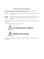
In addition, the following symbol may appear on the product:
ATTENTION–Refer to Manual
DANGER–High Voltage
Please read all safety instructions carefully and make sure you understand them fully before attempting to
use this product.
v
SAFETY WARNINGS AND CLEANING INSTRUCTIONS
DANGER
Opening the cover of this instrument is likely to expose dangerous voltages. Disconnect the
instrument from all voltage sources while it is being opened.
WARNING Using this instrument in a manner not specified by the manufacturer may impair the
protection provided by the instrument.
Cleaning Instructions
To clean the instrument exterior:
! Unplug the instrument from the ac power supply.
! Remove loose dust on the outside of the instrument with a lint-free cloth.
! Remove remaining dirt with a lint-free cloth dampened in a general-purpose detergent and water
solution. Do not use abrasive cleaners.
CAUTION To prevent moisture inside of the instrument during external cleaning, use only enough liquid
to dampen the cloth or applicator.
!
Allow the instrument to dry completely before reconnecting it to the power source.
vi
1
ORTEC MODEL 480
PULSER
1. DESCRIPTION
1.1. GENERAL
1.2. BASIC FUNCTION
The ORTEC 480 is a modular pulse generator
designed to simulate the detection of a nuclear
particle reaction in a solid-state or scintillation
detector. The unit features good stability as a
function of temperature and time, 1% overall
accuracy, and a front panel CaI control which
enables it to be calibrated to read directly in terms
of equivalent energy deposited in a detector. The
pulses are generated with a mercury relay switch
whose frequency is the frequency of the ac line.
The instrument has an internal stable reference
voltage that is effectively independent of the
modular power supply and ac line voltage changes.
The unit has four attenuator toggle switches for a
maximum attenuation of 1000:1. The direct output
precedes the attenuator switch and provides a
means of stable oscilloscope triggering. Two
terminators are provided with the 480: a charge
terminator and a 100 voltage terminator. The use
of a charge terminator allows the voltage output
pulse of the 480 to be converted to a charge pulse
for subsequent amplification by a charge-sensitive
preamplifier. A holder is provided on the rear panel
to store the charge terminator when it is not in use.
The 480 provides output pulses that are
characterized by a fast rise time and a slow
exponential decay time. These pulses are
generated by charging a capacitor to an internal
reference voltage through a mercury relay and then
discharging the capacitor through the switching
action of the mercury relay into a fixed resistive
load. The use of mercury-wetted relay contacts
provides a very fast rise time, typically less than 5
nsec 10-90% rise time, with an absolute minimum
of contact bounce or other perturbations of the
waveform for the first few microseconds. The
output impedance of the pulse generator on both
the direct and attenuated output is 100 . The direct
output provides a trigger pulse that allows the stable
synchronization of an oscilloscope or other timing
equipment from a signal which does not vary in
amplitude as the attenuators are switched in and
out. The attenuated output has a series of piattenuators between the mercury-wetted relay
contacts and the output BNC connector. This allows
the attenuation of the signal by a fixed amount,
depending upon the particular switch operated in
the series attenuator. The primary purpose of the
pulse generator is to simulate radiation detection
signals. Since the pulses are generated from an
electromechanical device (the mercury-wetted
relay), the frequency of the pulse generator is
correspondingly rather slow, i.e., the frequency of
the ac line.
S
This instrument is designed to meet the
recommended interchangeability standards of US
DOE Report TID-20893 (Rev.). An ORTEC
4001/4002 Series Bin and Power Supply provides
all necessary power through the rear module power
connector. The ORTEC 400 Series is designed so
that it is not possible to overload the Bin Power
Supply with a full complement of modules in the
Bin. However, this may not be true when the Bin
contains modules of other than ORTEC design. All
signal levels and impedances are compatible with
other modules in the ORTEC 400 Series.
S
2
2. SPECIFICATIONS
Neg/Pos Front panel slide switch, determines
polarity of the output signal.
2.1. PERFORMANCE
Temperature Stability 0.01%/°C, 0 to 50°C.
Line Voltage Stability 0.005% per 10% change in
line voltage.
Ripple and Noise 0.003% of pulse amplitude.
Nonlinearity ±0.25% of full scale.
Rise Time Exponential waveform, <10 nsec (10 to
90%).
Fall Time Exponential decay with 200- or 400sec time constant (depending on whether or not
the direct output is terminated).
:
2.3. OUTPUTS
Atten Front panel BNC connector provides positive
or negative dc-coupled output with an impedance of
100 .
S
Direct Front panel BNC connector provides
positive or negative dc-coupled. 0- to 10-V pulse
into a high impedance and 0- to 5-V max pulse into
100 . This is equivalent to a range of 0- to 220MeV energy referred to a silicon detector, when
used with associated charge terminator.
S
S
Accessories Included One 100
terminator and one charge terminator.
voltage
2.2. CONTROLS
2.4. ELECTRICAL AND MECHANICAL
Cal 22-turn potentiometer on front panel, covers
>2:1 amplitude span for normalization of Pulse
Height control to read directly in equivalent energy.
Pulse Height Front panel potentiometer, controls
output pulse height from zero volts to the maximum
determined by the Attenuator switches, the CaI
control setting, and the termination load.
Power Required
+24 V 60 mA; +12 V, 0 mA;
-24 V 60 mA; -12 V, 0 mA.
115 V ac, 8 mA (used only to drive relay).
Weight (Shipping) 4.1 lb (1.86 kg).
Weight (Net) 2.1. lb (0.95 kg).
Attenuator Front panel switches, provide step
attenuation over 1000:1 range with 1% resistors
(X2, X5, X10, X10).
Dimensions NIM-standard single-width module
(1.25 by 8.714 in.) Per TID-20893 (Rev.).
Off/On Front panel slide switch, allows internal
relay to be driven from the ac line.
3. INSTALLATION
3.1. GENERAL
The 480 contains no internal power supply but is
used in conjunction with an ORTEC 4001/4002
Series Bin and Power Supply, which is intended for
rack mounting. Therefore if vacuum tube
equipment is operated in the same rack with the
480, there must be sufficient cooling air circulating
to prevent any localized heating of the 480 and the
associated Bin and Power Supply. The temperature
of equipment mounted in racks can easily exceed
120°F (50°C) unless precautions are taken. The 480
should not be subjected to temperatures in excess
of 120°F.
3
3.2. CONNECTION TO POWER
Always turn off the Bin Power Supply when
inserting or removing modules. The 4001/4002 has
test Points on the Power Supply control Panel to
monitor the dc voltages. When using the 480
outside the 4001/4002, ensure that the power
jumper cable used properly accounts for the Power
Supply grounding circuits provided in the
recommended standards of US DOE TID-20893
(Rev.). Both high-quality and power-return ground
connections are provided to ensure proper
reference voltage feedback into the Power Supply,
and these must be preserved in remote
installations. Care must also be exercised to avoid
ground loops when the module is operated outside
the Bin.
If the 480 should be inserted in a bin that has no ac
voltage distribution, the unit will not operate since
the relay is driven from the ac line on pins 33 and
41.
4. OPERATION
4.1. PANEL CONTROLS
4.3. CONNECTOR DATA
Cal A 22-turn potentiometer on the front panel
varies the output pulse height continuously over a
2.5:1 range (approximately) to allow for
normalization of the Pulse Height dial setting.
CN 1 The Direct Output BNC connector provides a
dc-coupled output that looks back directly at the
relay and has an output impedance of 100 . The
output of this connector provides a constant output
voltage for a given setting of the Pulse Height
control independent of the position of the Attenuator
switches. Output voltage range is from 0 to 5 V
maximum into 100 and 0 to 10 V into a high
impedance. The direct output may or may not be
terminated with a 100 terminator. If the direct
output is terminated with a 100 terminator, the
decay time of the output pulse will change from a
nominal value of 400 sec to a value of 200 sec.
The polarity of the Direct Output pulse will be either
negative or positive as determined by the Neg/Pos
switch.
Pulse Height The Pulse Height potentiometer on
the front panel controls is the output pulse height
from zero volts to the maximum determined by the
Attenuator toggle switches and the termination load.
This 10-turn potentiometer has a calibration
linearity of ±0.25%.
Attenuators Four toggle switches on the front
panel control pi-attenuators in the attenuated output
line; the maximum attenuation is 1000:1. These
switches have an accuracy controlled by 1% metal
film resistors and depend upon the attenuated
output being terminated in 100 .
S
Off/On This front panel slide switch allows the
internal relay to be driven from the ac line. The
frequency of the ac line will be 50 to 60 Hz.
Neg/Pos The Polarity of the output signal will be
either negative (-) or Positive (+) as determined by
the setting of this front panel slide switch.
4.2. INITIAL TESTING AND OBSERVATION
OF PULSE WAVEFORMS
See Section 6.1 for test performance data.
S
S
S
S
:
:
CN 2 The Attenuated Output BNC connector
provides a dc-coupled output connector with an
output impedance of 100 . The attenuated output
has the Attenuators in series with it. The use of
these switches therefore alters the pulse amplitude
appearing at the attenuated output for a given
setting of the Pulse Height control. The attenuated
output should always be terminated with 100 . The
polarity of the output pulse will be determined by
the Neg/Pos switch.
S
S
TPI An oscilloscope test point is on the front panel
for monitoring the signal on the Direct Output BNC
connector CN1. This test point has a 470 series
resistor connecting it to CN1.
S
4
TP2 An oscilloscope test point is also on the front
panel for monitoring the signal on Attenuated
Output BNC connector CN2. This test point has a
470 series resistor connecting it to CN2.
S
4.4. TYPICAL OPERATING
CONSIDERATIONS
Charge and Voltage Terminators A charge
terminator that consists of a 100 shunt resistor
with a 2-pF series capacitor is supplied for use with
ORTEC charge-sensitive preamplifiers. When this
terminator is used, the maximum output pulse is 5
V on 10 pC (220 MeV for silicon diode detectors).
When the charge terminator is used to drive a
charge-sensitive preamplifier, a coaxial cable
having an impedance of approximately 100 (RG62/U) should be used between the pulse generator
and the charge terminator. The terminator should
be located at the input connector of the
preamplifier. The charge terminator may be used
with or without a detector being applied to the input
of a preamplifier. If a detector is connected to the
preamplifier, detector bias must be applied to
reduce the effective detector capacity shunting the
charge-sensitive preamplifier input. Also, with the
charge terminator used simultaneously with a
semiconductor detector, it must be remembered
that the charge terminator effectively shunts the
detector with approximately 2.5 pF of shunt
capacity, which will correspondingly degrade the
signal-to-noise performance of the preamplifier.
S
S
For voltage drive to an instrument under test, use
coaxial cable having an impedance of
approximately 100 (RG-62/U) between the pulse
generator and the instrument under test. Place a
100 termination at the instrument end of the cable
in shunt with the input of the instrument.
S
3. Adjust the amplifier gains and the bias level of
the biased amplifier to give a suitable output pulse.
4. Set the pulser Pulse Height potentiometer at the
energy of the alpha particles striking the detector
(e.g., for a 5.1-MeV alpha particle, set the dial at
510 divisions).
5. Turn on the pulser; use the CaI potentiometer
and the Attenuator switches to set the output due to
the pulser to the same pulse height and shape as
the pulse obtained in step 3.
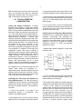
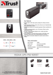
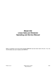
Amplifier Noise and Resolution Measurements
As shown in Fig. 4.1, a preamplifier, amplifier, pulse
generator, oscilloscope, and wide-band rms
voltmeter, such as the Hewlett- Packard 400D, are
required for this measurement. Connect a suitable
capacitor to the input to simulate the detector
capacitance desired. To obtain the resolution
spread due to noise:
1. Measure the rms noise voltage (Erms) at the linear
amplifier output.
Fig. 4.1. Measuring Amplifier and Detector Noise
Resolution.
S
Calibrating the Test Pulser and Amplifier for
Energy Measurements The 480 may easily be
calibrated so that the maximum Pulse Height dial
reading (1000 divisions) is equivalent to a specific
MeV loss in a radiation detector. The procedure is
as follows:
1. Connect the detector to be used to the
spectrometer system, i.e., preamplifier, main
amplifier, and biased amplifier.
2. Allow particles from a source of known energy
(alpha particles, for example) to fall on the detector.
2. Turn on the 480 and adjust the linear amplifier
output to any convenient readable voltage, Eo, as
determined by the oscilloscope.
The full width at half maximum (FWHM) resolution
spread due to the amplifier noise is then N(FWHM)
= 2.66 Erms Edial /Eo, where Edial is the pulser dial
reading in MeV, and the factor 2.66 is the correction
factor for rms to full width at half maximum (2.35)
and noise to rms meter correction (1.13) for
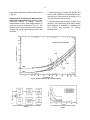
average indicating voltmeters such as the HewlettPackard 400D. The resolution spread will depend
upon the total input capacity, since the capacitance
degrades the signal-to-noise ratio much faster than
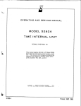
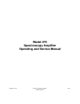
the noise. A typical resolution spread versus
5
external input capacitance in the RC mode is shown
in Fig. 4.2.
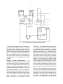
Amplifier Noise and Resolution Measurements
Using a Pulse Height Analyzer Probably the most
convenient method of making resolution
measurements is with a pulse height analyzer as
shown by the setup illustrated in Fig. 4.3. The
amplifier noise resolution spread can be measured
correctly with a pulse height analyzer and the 480
as follows:
1. Select the energy of interest with the 480, and
set the linear amplifier and biased amplifier gain
and bias level controls so that the energy is in a
convenient channel of the analyzer.
2. Calibrate the analyzer in keV per channel, using
the purser. (Full scale on the pulser dial is 10 MeV
when calibrated as described in "Calibrating the
Test Pulser and Amplifier for Energy
Measurements."
Fig. 4.2. Resolution Spread vs External Input Capacity.
Fig. 4.3. Measuring Resolution with a Pulse Height
Analyzer.
Fig. 4.4. Amplifier and Detector Noise vs Bias
Voltage.
6
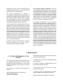
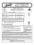
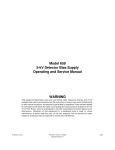
Fig. 4.5. Measuring Linearity by the Null-Balance Method.
3. Then obtain the amplifier noise resolution spread
by measuring the FWHM of the pulser spectrum.
The detector noise resolution spread for a given
detector bias can be determined in the same
manner by connecting a detector to the preamplifier
input. The amplifier noise resolution spread, of
course, must be subtracted. The detector noise will
vary with detector size and bias conditions as
indicated in Fig. 4.4 and possibly with ambient
conditions.
Amplifier Linearity Measurements
The
measurement of amplifier linearity can be quickly
and simply done by utilizing the method outlined in
Fig. 4.5. The method consists of bucking out two
voltage signals from low-impedance sources and
measuring the amplitude differential at a null point.
The following conditions of Fig. 4.5 should be
considered when linearity measurements are made.
The output impedance of the Direct Output must be
100 . The amplifier must be set in the inverting
mode of operation; i.e., for the negative input
shown, the amplifier must produce a positive
S
Output Pulse. The impedance seen from point A to
ac, or signal, ground via point C should be equal to
the impedance seen from point A to ac, or signal,
ground via point B. The diodes D should be
germanium units with high gm. The diodes can be
replaced with high-frequency germanium transistors
with the base connected to the collector so that the
emitter-base functions as the diode. Transistors
suitable for this test include 2N779, 2N964, 2N976,
2N2048. The diodes serve as bipolar voltage
clamps to limit the voltage swing at point A to the
forward voltage drop across the diodes. The dioderesistor network should be constructed so as to
minimize the stray capacitance around this network.
The network should be physically located on the
oscilloscope input connector for the same reason.
Initially the output of the Pulser and amplifier should
be set for 10 V. This should be measured with cars,
and consideration should be given for the output
impedance of both the Pulser and amplifier. By
observing the waveshape at point A (Fig. 4.5), the
fine gain of the amplifier and the attenuation
controls should be adjusted until a null is obtained
7
between time t1 and t2. At null, the sensitivity of the
oscilloscope should be set to 10 mV/cm for best
resolution of the null measurement.
The actual measurement of linearity is
accomplished by dialing the Pulse Height dial to 0,
resulting in the amplifier output being reduced to
zero. Since the Pulser supplies signals in parallel
both to the bridge for null and to the amplifier,
varying the Pulser output will have no effect on the
null if perfect amplifier linearity is assumed.
As an example of this method, assume that the
amplifier under test has essentially zero output
impedance. Set R1 equal to 100 and R2 equal to
200 . Let diodes D1 and D2 be 2N2048 connected
as diodes. Only one-half of the actual amplifier
output voltage can be measured directly at point A
due to the superposition of the outputs of the Pulse
generator via R1 and the amplifier via R2. To
specify nonlinearity as a percentage of full Output
voltage, the calibration of 10 mV/cm will be equal to
10 mV/5 V or 0.2% per cm. Therefore it is seen that
0.1% is quite easily resolved.
S
S
In addition to linearity measurements, it is obvious
that this method can be quite useful in
measurements of temperature stability.
Pulse Height Analyzer Calibration With the
Pulser calibrated to read directly in terms of energy
as described earlier in this section, the calibration of
a complete spectrometry system from preamplifier
to multichannel analyzer, i.e., analog to digital
converter (ADC), can readily be accomplished by
simply feeding into the preamplifier a calibrated
energy signal and observing the corresponding
channel into which it is assigned by the ADC.
An important consideration in this test involves
ensuring that the linear system "goes through zero,"
and that the output of the pulse generator is
properly terminated. The attenuator switches in the
480 have an accuracy controlled by 1% metal film
resistors and could be used to digitally check the
linearity of the spectrometer. In addition to the
attenuator accuracy, the Pulse Height control has
independent integral nonlinearity of ±0.25%. This
control therefore allows an integral linearity curve of
the ADC to be taken over the continuous range of
the ADC, i.e., from zero to the maximum address of
the ADC. Due to the better integral linearity control,
continuous scanning with the Pulse Height control
is the recommended method of checking for system
linearity. The linearity of the ADC can therefore be
determined by having previously taken the linearity
curve of the amplifier and preamplifier as outlined
earlier in this section.
5. MAINTENANCE
5.1. TESTING PERFORMANCE OF THE
PULSER
The following information is intended
the installation and checkout of the
instructions present information on
controls, waveforms at test points,
connectors.
as an aid in
480. These
front panel
and output
The following, or equivalent, test equipment is
needed:
Tektronix Model 580 Series Oscilloscope
100 BNC Terminators
Vacuum Tube Voltmeter
S
Before testing the performance of the 480, take the
following preliminary steps:
1. Visually check the module for possible damage
due to shipment.
2. Connect ac power to NIM-standard Bin and
Power Supply, 0RTEC 401 /402.
3. Plug module into Bin and check for proper
mechanical alignment.
4. Switch ac power on and check the dc Power
Supply voltages at the test points on the 402.
The performance test consists of the following:
8
1. Set the front panel controls on the 480 as
follows:
a. relay switch to On,
b. polarity switch to Pos,
c. Cal set to full clockwise and Pulse Height
control to 1000,
d. all Attenuator switches set to X1 position,
e. Direct Output terminated in 100 and kept
terminated in 100 throughout the test.
S
S
2. Apply power to the Bin and listen for running of
the mercury relay, which will be characterized by a
low frequency hum (50 or 60 Hz).
3. Set the relay switch to Off. Measure the dc
voltage from the wiper of the Pulse Height switch
on the rear panel to ground. It should be greater
than 9 V.
4. Dial the Cal control fully counterclockwise and
again measure the dc voltage from the wiper of the
Pulse Height switch to ground. It should be less
than 4 V. Turn the Cal control clockwise until the
voltage is 10 V.
5.2. ADJUSTMENT OF DECAY TIME OF
OUTPUT PULSE
As the 480 is normally supplied, the decay time of
the output pulse is essentially fixed. The output
Pulse will decay with the time constant of 400 sec
if the Attenuated output only is terminated in 100
and will decay with a time constant of
approximately 200 sec if both the Direct and Atten
Outputs are terminated. In the event that a time
constant shorter than 200 sec is desired, it is
necessary to parallel a fixed resistor from the
normally open contact of the mercury-wetted relay
to ground. The value of this shunting resistor will
depend upon the exponential time constant desired.
The addition of this resistor should physically be in
close proximity to the actual relay; that is to say, the
resistor should be added directly onto the etched
circuit board. Decay time constants as short as 10
sec can be accomplished quite easily.
:
S
:
:
5. Set the relay switch to On.
6. Measure the pulse at the direct output test point
TP1.
The pulse amplitude should be between the limits
of 4.0 and 6.0 V. The, pulse rise time (10-90%)
should be less than 10 nsec; the pulse fall time to
one-half of its maximum amplitude should be
between 230 and 290 sec. Do not remove the
100 terminator from the Direct Output.
S
9. Set the Polarity switch to Neg. There should be
no change in amplitude from the Pos position.
Observe the output with a sweep of 5 msec/cm and
look for "skipping" or other erratic behavior of the
relay.
:
S
7. Terminate attenuated output with 100 . Measure
the pulse at the attenuated Output test point. The
pulse amplitude should be between the limits of 4.0
and 6.0 V. The pulse rise time (10-90%) should be
less than 10 nsec; the pulse fall time to one-half of
its maximum amplitude should be between 110 and
150 sec.
:
8. Adjust the Pulse Height dial for a Pulse of 800
mV at the attenuated output test point. As the
Attenuator switches are switched in, the output
pulse should be between the following limits:
:
5.3. TABULATED TEST POINT
VOLTAGES
The following voltages are intended to indicate the
typical dc voltages measured on the etched circuit
board. In some cases the circuit will perform
satisfactorily even though due to component
variations there may be some voltages that
measure outside the given limits. Therefore the
voltages given should not be taken as absolute
values, but rather are intended to serve as an aid in
troubleshooting.
9
All voltages are measured from ground with dvm
having input impedance of 10 M or greater.
Polarity switch set to Neg.
S
5.4. SUGGESTIONS FOR
TROUBLESHOOTING
In situations where the 480 is suspected of
malfunction, it is essential to verify such
malfunction in terms of simple pulse generator
impulses at the output. In consideration of this, the
480 must be disconnected from its position in any
system, and routine diagnostic analysis performed
on the Pulser with a vacuum tube voltmeter and
oscilloscope. It is imperative that testing not be
performed with any amplifier system until the
Pulser performs satisfactorily by itself. The testing
instructions of Section 6.1 of this manual and the
circuit description in Section 5 are intended to
provide assistance in locating the region of trouble
and repairing the malfunction. The guide plate and
shield cover can be completely removed from the
module to enable oscilloscope and voltmeter
observations with a minimum chance of
accidentally short circuiting portions of the etched
board.
The 480 may be returned to ORTEC for repair
service at nominal cost. Our standard procedure
requires that each repaired instrument receive the
same extensive quality control tests that a new
instrument receives. Contact our Customer Service
Department, (865) 483-2231, for shipping
instructions before returning an instrument.
10
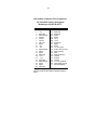
Bin/Module Connector Pin Assignments
For Standard Nuclear Instrument
Modules per DOE/ER-0457T.
Pin
1
2
3
4
5
6
7
8
9
10
11
12
13
14
15
*16
*17
18
19
20
21
22
Function
+3 V
-3V
Spare bus
Reserved bus
Coaxial
Coaxial
Coaxial
200 V dc
Spare
+6 V
-6V
Reserved bus
Spare
Spare
Reserved
+12 V
- 12 V
Spare bus
Reserved bus
Spare
Spare
Reserved
Pin
23
24
25
26
27
*28
*29
30
31
32
*33
*34
35
36
37
38
39
40
*41
*42
G
Function
Reserved
Reserved
Reserved
Spare
Spare
+24 V
- 24 V
Spare bus
Spare
Spare
117 V ac (hot)
Power return ground
Reset (Scaler)
Gate
Reset (Auxiliary)
Coaxial
Coaxial
Coaxial
117 V ac (neutral)
High-quality ground
Ground guide pin
Pins marked (*) are installed and wired in
ORTEC’s 4001A and 4001C Modular System
Bins.