1
Model 661
Ratemeter
Operating and Service Manual
Printed in U.S.A.
ORTEC® Part No. 740380
Manual Revision D
1202
Advanced Measurement Technology, Inc.
a/k/a/ ORTEC®, a subsidiary of AMETEK®, Inc.
WARRANTY
ORTEC* warrants that the items will be delivered free from defects in material or workmanship. ORTEC makes
no other warranties, express or implied, and specifically NO WARRANTY OF MERCHANTABILITY OR
FITNESS FOR A PARTICULAR PURPOSE.
ORTEC’s exclusive liability is limited to repairing or replacing at ORTEC’s option, items found by ORTEC to
be defective in workmanship or materials within one year from the date of delivery. ORTEC’s liability on any
claim of any kind, including negligence, loss, or damages arising out of, connected with, or from the performance
or breach thereof, or from the manufacture, sale, delivery, resale, repair, or use of any item or services covered
by this agreement or purchase order, shall in no case exceed the price allocable to the item or service furnished
or any part thereof that gives rise to the claim. In the event ORTEC fails to manufacture or deliver items called
for in this agreement or purchase order, ORTEC’s exclusive liability and buyer’s exclusive remedy shall be release
of the buyer from the obligation to pay the purchase price. In no event shall ORTEC be liable for special or
consequential damages.
Quality Control
Before being approved for shipment, each ORTEC instrument must pass a stringent set of quality control tests
designed to expose any flaws in materials or workmanship. Permanent records of these tests are maintained for
use in warranty repair and as a source of statistical information for design improvements.
Repair Service
If it becomes necessary to return this instrument for repair, it is essential that Customer Services be contacted in
advance of its return so that a Return Authorization Number can be assigned to the unit. Also, ORTEC must be
informed, either in writing, by telephone [(865) 482-4411] or by facsimile transmission [(865) 483-2133], of the
nature of the fault of the instrument being returned and of the model, serial, and revision ("Rev" on rear panel)
numbers. Failure to do so may cause unnecessary delays in getting the unit repaired. The ORTEC standard
procedure requires that instruments returned for repair pass the same quality control tests that are used for
new-production instruments. Instruments that are returned should be packed so that they will withstand normal
transit handling and must be shipped PREPAID via Air Parcel Post or United Parcel Service to the designated
ORTEC repair center. The address label and the package should include the Return Authorization Number
assigned. Instruments being returned that are damaged in transit due to inadequate packing will be repaired at the
sender's expense, and it will be the sender's responsibility to make claim with the shipper. Instruments not in
warranty should follow the same procedure and ORTEC will provide a quotation.
Damage in Transit
Shipments should be examined immediately upon receipt for evidence of external or concealed damage. The carrier
making delivery should be notified immediately of any such damage, since the carrier is normally liable for damage
in shipment. Packing materials, waybills, and other such documentation should be preserved in order to establish
claims. After such notification to the carrier, please notify ORTEC of the circumstances so that assistance can be
provided in making damage claims and in providing replacement equipment, if necessary.
Copyright © 2002, Advanced Measurement Technology, Inc. All rights reserved.
*ORTEC® is a registered trademark of Advanced Measurement Technology, Inc. All other trademarks used
herein are the property of their respective owners.
iii
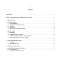
CONTENTS
WARRANTY . . . . . . . . . . . . . . . . . . . . . . . . . . . . . . . . . . . . . . . . . . . . . . . . . . . . . . . . . . . . . . . . . . . . . . . ii
SAFETY WARNINGS AND CLEANING INSTRUCTIONS . . . . . . . . . . . . . . . . . . . . . . . . . . . . . . . . . . . . . v
1. DESCRIPTION . . . . . . . . . . . . . . . . . . . . . . . . . . . . . . . . . . . . . . . . . . . . . . . . . . . . . . . . . . . . . . . . . . . 1
2. SPECIFICATIONS* . . . . . . . . . . . . . . . . . . . . . . . . . . . . . . . . . . . . . . . . . . . . . . . . . . . . . . . . . . . . . . .
2.1. PERFORMANCE . . . . . . . . . . . . . . . . . . . . . . . . . . . . . . . . . . . . . . . . . . . . . . . . . . . . . . . . . . . . .
2.2. CONTROLS AND INDICATORS . . . . . . . . . . . . . . . . . . . . . . . . . . . . . . . . . . . . . . . . . . . . . . . . .
2.3. INPUTS . . . . . . . . . . . . . . . . . . . . . . . . . . . . . . . . . . . . . . . . . . . . . . . . . . . . . . . . . . . . . . . . . . . .
2.4. OUTPUTS . . . . . . . . . . . . . . . . . . . . . . . . . . . . . . . . . . . . . . . . . . . . . . . . . . . . . . . . . . . . . . . . . .
2.5. ELECTRICAL AND MECHANICAL . . . . . . . . . . . . . . . . . . . . . . . . . . . . . . . . . . . . . . . . . . . . . . . .
1
1
2
3
3
3
3. INSTALLATION . . . . . . . . . . . . . . . . . . . . . . . . . . . . . . . . . . . . . . . . . . . . . . . . . . . . . . . . . . . . . . . . . .
3.1. GENERAL
..........................................................................
3.2. CONNECTION TO POWER . . . . . . . . . . . . . . . . . . . . . . . . . . . . . . . . . . . . . . . . . . . . . . . . . . . . .
3.3. SIGNAL CONNECTIONS TO THE 661 INPUTS . . . . . . . . . . . . . . . . . . . . . . . . . . . . . . . . . . . . .
3.4. SELECTING ANALOG OUTPUT RANGE
..........................................................................
3
3
3
4
4
4. OPERATING INSTRUCTIONS . . . . . . . . . . . . . . . . . . . . . . . . . . . . . . . . . . . . . . . . . . . . . . . . . . . . . . . 5
4.1. GENERAL . . . . . . . . . . . . . . . . . . . . . . . . . . . . . . . . . . . . . . . . . . . . . . . . . . . . . . . . . . . . . . . . . . 5
4.2. RESPONSE TIME . . . . . . . . . . . . . . . . . . . . . . . . . . . . . . . . . . . . . . . . . . . . . . . . . . . . . . . . . . . . 5
5. THEORY OF OPERATION . . . . . . . . . . . . . . . . . . . . . . . . . . . . . . . . . . . . . . . . . . . . . . . . . . . . . . . . . 5
6. MAINTENANCE AND ADJUSTMENTS . . . . . . . . . . . . . . . . . . . . . . . . . . . . . . . . . . . . . . . . . . . . . . . . 7
6.1. ADJUSTMENTS . . . . . . . . . . . . . . . . . . . . . . . . . . . . . . . . . . . . . . . . . . . . . . . . . . . . . . . . . . . . . . 7
6.2. FACTORY REPAIR SERVICE . . . . . . . . . . . . . . . . . . . . . . . . . . . . . . . . . . . . . . . . . . . . . . . . . . . 7
iv
v
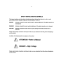
SAFETY WARNINGS AND CLEANING INSTRUCTIONS
DANGER
Opening the cover of this instrument is likely to expose dangerous voltages. Disconnect the
instrument from all voltage sources while it is being opened.
WARNING Using this instrument in a manner not specified by the manufacturer may impair the
protection provided by the instrument.
Cleaning Instructions
To clean the instrument exterior:
! Unplug the instrument from the ac power supply.
! Remove loose dust on the outside of the instrument with a lint-free cloth.
! Remove remaining dirt with a lint-free cloth dampened in a general-purpose detergent and water
solution. Do not use abrasive cleaners.
CAUTION To prevent moisture inside of the instrument during external cleaning, use only enough liquid
to dampen the cloth or applicator.
!
Allow the instrument to dry completely before reconnecting it to the power source.
vi
1
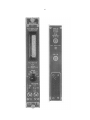
ORTEC MODEL 661 RATEMETER
1. DESCRIPTION
The ORTEC Model 661 Ratemeter measures the
counting rate of randomly arriving pulses, or the
frequency of periodic signals in the range of 0 to 107
counts/s (0 to 10 MHz). This range of counting rates
is covered with 18 different scales. The scales are
arranged in a 25, 50, 100 sequence from 25
counts/s to 107 counts/s full scale.
A positive input accepts and counts signals in the
amplitude range of +150 mV to +10 V. The signals
can be either positive unipolar pulses or bipolar
pulses. With bipolar pulses, only the positive lobe
will be counted. The positive input includes a
discriminator whose threshold can be adjusted over
the range of 150 mV to 10 V. In many cases this
eliminates the need for an external precision
discriminator. Only those pulses whose amplitudes
exceed the positive discriminator threshold are
counted.
A negative input is provided to count NIM-standard
fast negative logic pulses in the amplitude range of
-600 to -1800 mV. The negative input threshold is
fixed at -250 mV. Pulses as narrow as 4 ns can be
counted through this input.
A front-panel switch permits selection of the
ratemeter response time, which determines the
random error in the measurement. Three response
times are provided, FAST, MED, and SLOW. When
measuring the steady state counting rate of
randomly arriving pulses, the standard deviation of
the instantaneous meter reading is <1% on the
SLOW response, <3% on the MED response, and
<10% on the FAST response setting (Table 1).
The setting time for 1% precision on the SLOW
response time can be quite long at low counting
rates. To overcome this limitation the 661
Ratemeter includes a special, fast response circuit.
With this feature the measurement can be started
with the RESPONSE switch in the FAST position.
When the meter has settled, the RESPONSE switch
is moved to the MED position, and then to the
SLOW setting. This technique significantly reduces
the time to settle to 1% precision, since the FAST,
MED, and SLOW response times are maintained in
a 1:9:100 ratio.
A rear-panel ANALOG OUTPUT is included for use
with strip chart recorders. The full-scale output can
be selected to be 100 mV, 1 V, or 10 V. A ±10%
fine-adjustment potentiometer is provided for the
calibration of this output.
2. SPECIFICATIONS*
2.1. PERFORMANCE
COUNTING RATES Measures counting rates in
the range of 0 to 10 MHz (0 to 107 counts/s).
METER RANGES Provides 18 full-scale meter
ranges from 25 counts/s to 107 counts/s in a 25, 50,
100 step sequence.
ANALOG OUTPUT RANGES Same as meter
ranges. Full-scale output can be selected as
100 mV, 1 V, or 10 V.
*Specifications subject to change without notice.
PULSE PAIR RESOLUTION
positive and negative inputs.
<40 ns on both
STANDARD DEVIATION The ratemeter time
constants yield a standard deviation in the
instantaneous meter reading of <10% for the FAST
RESPONSE, <3% for the MED RESPONSE, and
<1% for the SLOW RESPONSE setting, when
measuring the steady state counting rate of
randomly spaced events. See Table 1 for details.
CALIBRATION ACCURACY
Meter: <2% of full scale.
Analog Output: <1% of full scale.
2
NONLINEARITY
analog output.
<±0.1% of full scale at the
TEMPERATURE SENSITIVITY
scale per °C, 0 to 50°C.
ANALOG OUTPUT RANGE Printed circuit board
jumper, W1, allows selection of a 100 mV, 1 V, or
10 V full-scale output for the ANALOG OUTPUT.
<0.02% of full
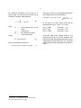
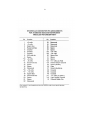
Table 1. Standard Deviation for Various Scale
and Response Settings.
2.2. CONTROLS AND INDICATORS
METER Front-panel meter provides visual reading
of the counting rate. Actual value for the full-scale
reading is determined by the product of the RANGE
and MULTIPLIER switch settings.
RANGE Front-panel six-position switch provides
the coarse selection of the full-scale counting rate.
Coarse ranges of 50, 500, 5000, 50,000, 500,000,
and 5,000,000 counts/s are selectable.
MULTIPLIER Front-panel three-position switch
provides a fine adjustment of the full-scale value
selected by the RANGE switch. The full-scale
counting rate is the product of the RANGE and
MULTIPLIER values. The MULTIPLIER switch
selects a multiplying factor of 0.5, 1.0, or 2.0.
RESPONSE Front-panel 3-position switch selects
the ratemeter response time. The three response
times are also controlled by the RANGE switch to
ensure standard deviations of <10% on the FAST
setting, <3% on MED, and <1% on the SLOW
setting. See Table 1 for details. The FAST, MED,
and SLOW response times are maintained in a
1:9:100 ratio. A special circuit permits using the
advantage of the shorter time constants on the
FAST and MED switch positions to significantly
reduce the time taken to settle to 1% precision on
the SLOW position. Using this feature, the
measurement is started with the RESPONSE switch
in the FAST position. When the meter has settled,
the RESPONSE switch is moved to the MED
position. After the meter has settled again, the
switch is moved to the SLOW setting. This
technique provides a significantly shorter response
time than would be obtained by leaving the
ratemeter in the SLOW RESPONSE setting.
THRESH (Threshold)
A front-panel 20-turn
potentiometer provides screwdriver adjustment of
the positive input discriminator threshold over the
range of 150 mV to 10 V.
Full-Scale
Frequency
STANDARD DEVIATION (%)
SLOW
MED
FAST
25 Hz
1.0
3.0
10.0
50 Hz
0.7
2.0
7.0
100 Hz
0.5
1.5
5.0
250 Hz
1.0
3.0
10.0
500 Hz
0.7
2.0
7.0
1 kHz
0.5
1.5
5.0
2.5 kHz
1.0
3.0
10.0
5 kHz
0.7
2.0
7.0
10 kHz
0.5
1.5
5.0
25 kHz
1.0
3.0
10.0
50 kHz
0.7
2.0
7.0
100 kHz
0.5
1.5
5.0
250 kHz
0.3
1.0
3.0
500 kHz
0.22
0.7
2.0
1 MHz
0.16
0.5
1.6
2.5 MHz
0.1
0.3
1.0
5 MHz
0.07
0.2
0.7
10 MHz
0.05
0.15
0.5
FULL SCALE ADJ
A rear-panel 20-turn
potentiometer provides a ±10% adjustment of the
full-scale output voltage for the selected range of
the ANALOG OUTPUT.
3
2.3. INPUTS
POS IN Front- and rear-panel BNC connectors
accept positive polarity inputs for counting. Input
signals can be unipolar or bipolar. The ratemeter
will count signals whose amplitudes are more
positive than the input discriminator threshold
(THRESH) setting. Linear input range is 0 to +10 V.
Inputs protected to ±25 V. Minimum pulse width
above threshold is 20 ns at a 50% duty cycle. Input
impedance is 1000 to ground, dc-coupled.
S
NEG IN Front-panel BNC connector accepts NIMstandard, fast negative logic pulses with amplitudes
in the range of -600 to -1800 mV. Negative input
discriminator has a fixed threshold of -250 mV.
Minimum pulse width at threshold is 4 ns. Input
to ground. Input protected to
impedance is 50
±25 V at a 10% duty cycle.
S
2.4. OUTPUTS
METER 5.08 cm (2 in.) edge reading meter with a
2% meter movement.
ANALOG OUTPUT Rear-panel BNC connector
provides an output voltage proportional to the
measured counting rate for use with a strip chart
recorder. Output is selectable for a 0 to 100 mV, 0
to 1 V, or 0 to 10 V range, using the analog output
range jumper. A calibration adjustment of ±10% of
full scale is possible with the FULL SCALE ADJ
potentiometer. Output impedance is 50 , with
short-circuit protection. Maximum output current is
10 mA.
S
THRESH (Threshold)
Front-panel test point
adjacent to the THRESH potentiometer monitors
the threshold voltage of the positive input
discriminator. Test point voltage measured with a
high-impedance voltmeter is 1/10 the actual
threshold voltage of the positive input discriminator.
Output impedance is 15,000 .
S
2.5. ELECTRICAL AND MECHANICAL
POWER REQUIRED The 661 Ratemeter derives
its power from a NIM Bin supplying ±12 V and
±24 V, such as the ORTEC Model 4001A/4002A
NIM Bin and Power Supply. The power required is
+12 V at 95 mA, -12 V at 40 mA, and +24 V at
10 mA.
WEIGHT
Net 0.68 kg (1.5 lb).
Shipping 1.6 kg (3.5 lb).
DIMENSIONS NIM-standard single-width module,
3.43 × 22.13 cm (1.35 × 8.714 in.) front panel per
DOE/ER-0457T.
3. INSTALLATION
3.1. GENERAL
3.2. CONNECTION TO POWER
The 661 Ratemeter operates on power that must be
furnished from a NIM-standard bin and power
supply such as the ORTEC 4001/4002 Series. The
bin and power supply is designed for relay rack
mounting. If the equipment is to be rack mounted,
be sure that there is adequate ventilation to prevent
any localized heating of the components that are
used in the 661. The temperature of equipment
mounted in racks can easily exceed the maximum
limit of 50°C unless precautions are taken.
The 661 contains no internal power supply;
therefore, it must obtain power from a NIM-standard
bin and power supply. Always turn the bin power off
before inserting or removing modules. After all
modules have been installed in the bin, check the
dc voltage levels from the power supply to see that
they are not overloaded. All ORTEC bins and power
supplies have convenient test points on the power
supply control panel to permit monitoring these dc
levels. If any one or more of the dc levels indicates
an overload, some of the modules will need to be
moved to another bin to achieve operation.
4
3.3. SIGNAL CONNECTIONS TO THE 661
INPUTS
3.4. SELECTING ANALOG OUTPUT
RANGE
The 661 is equipped with two separate input
circuits. One is for positive input signals and the
other one is for negative-NIM signals. These two
inputs are “OR-ed” together inside the module, so
you can make a connection to one or the other but
not to both.
The 661 Ratemeter has three analog output ranges:
100 mV, 1 V and 10 V. The selection of the output
range is made by moving a jumper located inside
the module. The 100-mV range is selected when the
unit is shipped. Do the following to change the
output range:
For positive input signals the input labeled POS IN
should be used. The input is available on both the
front and rear panels. The positive input signal goes
through a lower-level discriminator inside the
module. The discriminator level is set by the trimpot
located on the front panel labeled THRESHOLD.
The discriminator voltage may be monitored on the
test point below the trimpot. The voltage read at the
test point is 1/10 the actual discriminator voltage.
1. Remove all cables connected to the 661 and
remove the module from the NIM bin.
2. Lay the module on its right side and remove the
four screws that hold the left side plate in place;
then remove the left side plate.
3. Locate jumper W1. It is located in the upper lefthand corner of the circuit board and is labeled
W1. See Fig. 3.
4. Move the jumper to the appropriate row of pins.
For 10 V the jumper should be toward the top of
the module. For 1 V range the jumper should be
located on the center row of pins, and for
100 mV the jumper should be located on the
lower row of pins.
5. Replace the left side plate and the four screws
that hold it in place.
The negative-NIM input is located on the front panel
only, and it is labeled NEG IN.
5
4. OPERATING INSTRUCTIONS
4.1. GENERAL
To operate the 661 Ratemeter, first insert the
module into a NIM Bin that supplies ±12 V and
±24 V. Connect the input signal and adjust the
threshold if necessary. The rate of the input signal
is read directly from the front-panel meter. Note that
the multiplier switch settings change the meter
scale. When the multiplier switch is in the ×0.5
position, then the value read on the meter should be
divided by 2. Likewise, when the multiplier switch is
in the ×1.0 position, the count rate may be read
directly off the meter, and when the multiplier switch
is in the ×2.0 position, the value read off the meter
should be multiplied by 2.
4.2. RESPONSE TIME
constant function found on other ratemeters. The
switch has three positions labeled FAST, MED, and
SLOW. If the switch is in the SLOW position, the
standard deviation of the instantaneous count-rate
reading is better than 1%. In the MED position the
standard deviation is less than 3%, and in the FAST
position the standard deviation is less than 10%.
Table 1 gives the actual standard deviations at full
scale for the various combinations of scale
selections and response time.
The response switch can be moved without
affecting the measurement, so an accurate reading
can be made very quickly by first placing the
response switch in the fast position and then
moving it to the medium or slow position for the
final reading after the initial charging has taken
place.
The front-panel control labeled REPONSE is
equivalent to the standard deviation or time
5. THEORY OF OPERATION
The 661 Ratemeter operates by applying a fixed
amount of charge onto a capacitor for each input
signal, and by draining this charge off at a rate
proportional to the amount of charge. This is most
easily accomplished by means of an operation
amplifier with an RC parallel feedback network.
The input signal, if accepted by the lower-level
discriminator, will produce an output that goes to the
prescale network. If the multiplier switch is in the 0.5
position and the range is less than 500 kHz, then
the output from the prescaler will change states
every time a pulse comes in (i.e., the frequency is
divided by 2). This signal goes to the monostables.
One of the monostables triggers on the positive
edge, and the second triggers on the falling edge.
This effectively doubles the frequency back to its
original value. Each time one of the monostable
triggers, a negative transition occurs at the collector
of Q1. This transition passes through C3 and Q2
(diode connected transistor) to the input of the
amplifier to produce a positive output signal. When
the signal at the collector of Q1 goes positive, the
signal path is through C3 and Q5 to ground, with Q2
being cut off so that the output is not changed by
the positive transition.
The response of the output to a single input is:
e = V(C3/Cf) exp(-t/RfCf)
(1)
so that the amplitude initially “steps up” by an
amount equal to VC3/Cf and falls with an
exponential time constant of RfCf.
The average value of the output is obtained when
the current through Rf is equal to the current
supplied from Q1. If n represents the average input
rate, then the input current is:
i = nQ or i = nVC3
(2)
and the current through Rf is simply:
iR = Eo/Rf
(3)
where Eo is the average value of the output voltage.
Since these two currents must be equilibrium,
Eo = nVC3Rf.
(4)
6
The statistical fluctuations of the output for a
random input rate can be derived by the use of
Campbell’s1 theorem, which says that
Using Eqs. (4) and (7), the % standard deviation of
the average output can be obtained as
% Std. Dev. = 100 × eo/Eo = 100/
∞
eo = n ∫
o
2
f (t ) 2 dt
n =
f(t) =
=
so that
(6)
The rms variations of the output is
eo(rms) = (C3V/Cf) × nRfCf/2 = nC3VRf/2.
1
C
f
).
(8)
At full scale in the 661, these values can be
calculated easily for n = 25f Rf = 107, and Cf.
mean squared value of the
output
average rate
time response of output
V(C3/Cf)exp(-t/RfCf)
eo2 = n(C3)2V2Rf/2Cf.
f
(5)
where
eo2 =
( 2 nR
(7)
Campbell, N.R., “The Study of Discontinuous Phenomena,”
Proc. Camb. Philos. Soc., 15:117 (1908)
:
:
:
(a) Cf = 20 F
(b) Cf = 2 F
(c) Cf = 0.2 F
% Std. Dev. = 1%
% Std. Dev. = 3%
% Std. Dev. = 10%
In the 661, when n=50 a digital divide by 2 is
employed and Rf and Cf are not changed. This
effectively divides the standard deviation numbers
obtained above by the square root of 2. This is the
method that was used to generate the numbers in
Table 1.
7
6. MAINTENANCE AND ADJUSTMENTS
6.1. ADJUSTMENTS
1. Integrator DC Balance Adjustment. With no
signals applied to the input, the dc level at test
point 1 should be zero volts. Use R4 to make
the adjustment.
2. Analog DC Balance Adjustment. With no signal
applied, the dc level at the analog output should
be zero volts. Adjust Resistor R4 to obtain this
condition.
3. Meter Zero. With the instrument under power
and no input applied, the meter can be zeroed
by adjusting the pot located on the back of the
meter. This pot should be adjusted until the
meter reads 0. This adjustment should not be
made until adjustment 1 is made.
4. Meter Calibrate. With a known input rate
(preferably periodic of value above 100 cps)
adjust R9 so that the meter reads correctly. The
range switch should not be in the 50 position.
5. 100/50/25 cps Ranges. The 25, 50 and 100 cps
ranged are trimmed to read correctly by
adjusting R44 after adjustments 1, 3, and 4
have been checked for correctness. To make
the adjustment, use a signal of known rate
below 100 cps — a line frequency pulse is often
convenient. Adjust R44 until meter reads
correctly. Take care to allow enough time for the
reading to stabilize before changing the value of
R44. It takes about four minutes for a stable
reading at 60 cps and 1% Std. Dev.
6.2. FACTORY REPAIR SERVICE
This instrument can be returned to ORTEC for
service and repair at a nominal cost. Our standard
procedure for repair ensures the same quality
control and checkout as for new instrument. Always
contact the Customer Service Department at
ORTEC, (865) 482-4411, before sending in an
instrument for repair to obtain shipping instructions.
A Return Authorization Number is required, and will
be assigned to the unit. Write this number on the
address label and on the package to ensure prompt
attention when it reaches the factory.
8