1
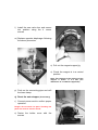
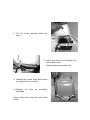
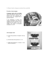
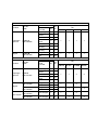
SERVICE MANUAL SECOH AIR PUMPS Models covered in this manual: SLL-20, 30, 40 & 50 EL-60, 80-15, 80-17 & 100 EL-120W, 150 & 200 Contents 1. Prior to maintenance and Service 2. Maintenance 3. Air filter cleaning / replacement 4. Valve box and diaphragm replacement 5. Resetting auto stopper 6. Magnet replacement 7. Diagnosis of failures 8. Technical Specification 9. Test data (resistance table) 10. Spares Kits and replacement parts 1. Prior to maintenance and service • Prior to maintenance and service, read and keep this manual carefully. • Follow the safety instructions! • Servicing and maintenance as described in this manual should be carried out by an authorised service facility. • Always disconnect power supply before servicing. Failure to do so could result in electrical shock, personal injury or death. • Do not touch live parts. Touching live parts will result in electric shock. 2. Maintenance Cleaning the air filter The air filter must be cleaned every 3 to 4 months to insure correct operation and replaced regularly. Occasional checks Is air blowing out properly? Is the air pump making abnormal noise or vibrations? Is the temperature of the air pump not abnormally high? Is the power cord or plug damaged or discoloured? Î If any irregularity is found, read DIAGNOSIS OF FAILURES. 3. Filter element cleaning or replacement a) Undo the truss head screw of the filter cover. b) Remove the filter cover, by firmly pulling it off. c) Remove the filter element and brush off any dust particles by hand. If heavily clogged with dust, wash in a neutral detergent followed by a thorough rinsing in water. Allow to dry in the shade. Note: Do not use benzene or thinner to clean filter element as it can be damaged! d) After cleaning reassemble the filter element back in place. Make sure to put the harder side of the filter facing downwards. Press in the filter cover. e) Secure the filter cover by the truss head screw. 4. Valve box and diaphragm replacement a) Undo the 4 corner bolts of the overall cover. b) Remove the overall cover. If it is hard to remove, insert a screwdriver in the slot provided. c) Pull out the bushing. d) Remove the shock absorber e) Undo the 4 screws of the holder cover. Note: It is easier to change one diaphragm at a time. f) Insert the magnet support jig in the 4 corners, between the magnet and the core. Note: The magnet support jig (carton strips) is included in the service repair kit. g) Undo the 4 screws of the valve box. h) Slide down the hose clamp, pull off the connecting pipe and remove the valve box. i) Undo the nut or bolt and remove the diaphragm (Nut: SLL series & EL-60, 80-15 & 120W - Bolt: EL-80-17, 100, 150 & 200). j) Set the new diaphragm and fix it by the nut or bolt (torque, see table at appendix). k) Insert the magnet supporter jig in the 4 corners between the magnet and the core. Note: Make sure that the magnet is in the centre of the solenoids. l) Install the new valve box and secure into position using the 4 corner screws. m) Replace opposite diaphragm following the above procedure. n) Pull out the magnet support jig. o) Check the magnet is in a central position. Note: The tolerance of the centring of the magnet is within +/- 0.5 mm (see dimension “d” of sketch in appendix). p) Push on the connecting pipe and refit the hose clamp. q) Reset the auto stopper (If necessary) r) Connect power cord to confirm proper operation. Danger: Do not touch live parts. Touching live parts will result in electric shock! s) Fasten the holder cover with the screws. t) Put the shock absorber back into place. u) Insert the power cord bushing into the location notch. Note: It locates into the inner slot! v) Replace the overall cover and secure by using the nuts and bolts. w) Replace air described. filter as previously Secure filter cover using the truss head screw. 5. Reset auto stopper (protective switch) Function of auto stopper A running pump with a broken diaphragm may cause a major break down and excessive repair cost. To prevent this from occurring, ELseries pumps are equipped with a protective switch. If the diaphragm is broken, the magnet reciprocates with abnormal amplitude and the projection of the magnet hits the slider of the auto stopper. The contact is interrupted and power is cut off. Auto stopper reset a) Follow the procedure of chapter 4 from a) to e) b) Set the slider at the position L1 = L2. c) Follow the procedure of section 4 from point r) to point w). 6. Magnet replacement a) Follow the procedure of section 4 from a) to i). b) Remove diaphragm and pull out opposite diaphragm and magnet from other side. c) Assemble new magnet diaphragm with nut or bolt. and d) Insert the diaphragm and the magnet between the solenoids. The projection should be upward. e) Install replacement diaphragm to opposite side. f) Follow the procedure of chapter 4 from k) to w). 7. Diagnosis of Failures Problem Cause Action Pump does not work Power plug is disconnected Plug in and check if electricity is available Check electrical continuity with circuit tester Open cover to check for damage on diaphragm Open cover to check for damage or disconnection Re-connect or replace L-Tube Re-position pump Cord is broken (Internal wiring damaged) Auto stopper activated Excessive noise Discharged air volume decreases Valves or diaphragm are damaged L-Tube is damaged or disconnected Pump is in touch with surrounding articles. Air filter is clogged Air diffuser or pipe is clogged Abnormal temperature arises Pump sometimes operates and sometimes not. * Air filter is clogged Air diffuser or pipe is clogged Air filter is or diffuser is clogged Clean or replace air filter Clean air diffuser and check piping Clean or replace air filter Un-block air diffuser or pipe Clean or replace air filter or diffuser *A decrease in airflow (caused by clogged air filter or air diffuser) may lead to an extraordinary rise in operating temperature. This will activate a thermal protector and stop the pump. When the temperature reduces, the pump will automatically restart. If in doubt about any service or maintenance procedures, please call http://ledoed.com.ua/ 8. Technical Specifications Model Voltage Frequency Optimal Press. Open Flow Max Power Outlet dia. Weight Standard accessories V Hz bar L/min W mm kg Model Voltage Frequency Optimal Press. Open Flow Max Power Outlet dia. Weight Standard accessories V Hz bar L/min W mm kg Model Voltage Frequency Optimal Press. Open Flow Max Power Outlet dia. Weight Standard accessories SLL-20 52 EL-60 0.2 105 EL-120W V Hz bar L/min W mm kg 225 SLL-30 SLL-40 As shown in the name plate Applied to 50 0.2 60 68 As shown in the name plate OD 19 mm 4.5 L-Joint hose (with hose band) SLL-50 EL-80-17 EL-80-15 As shown in the name plate Applied to 50 0.2 0.2 115 120 As shown in the name plate OD 19 mm 8.5 L-Joint hose (with hose band) EL-100 EL-150 As shown in the name plate Applied to 50 0.25 265 As shown in the name plate OD 27 mm 16 L-Joint hose (with hose band) 0.2 75 0.2 145 EL-200 310 9. Testing Data a) Solenoid resistance table Voltage: 230V, 50Hz Tolerance: +/- 10% SLL-20 & 30 models: Solenoids are in series connection Other models: Solenoids are in parallel connection Total R SLL-40 SLL-50 EL-60 EL-80-15 EL-80-17 EL-100 EL-120W EL-150 EL-200 Single R 86.5 60.8 36.7 21.9 33.1 20.0 16.2 16.6 10.0 10. Spare Part Kits Only use genuine SECOH replacement parts. Non-standard parts will have a detrimental effect on overall pump life and performance. In order to ensure long service and operation, it is recommended diaphragms and valve boxes are replaced once a year. All parts; magnets, filters, service kits and diaphragms are available from http://ledoed.com.ua/ online site and can be despatched immediately. We also stock a complete range of Secoh pumps for replacement purposes and these can also be used to replace defective pumps of other brands with ease. 173.0 121.7 73.4 43.7 66.2 40.0 64.7 66.2 40.0 Kit Name Diaphragm repair kit Magnet Kit name Diaphragm repair kit Magnet Part No. Code K-SLL-D EM-0359025 K-SLL-M EM-0351008 Part No. Code SLL SERIES Contents Pos Parts Qty No included Diaphragm Diaphragm holder Nut Valve box & valve Filter element Filter cover packing Tank base packing Magnet Nut 2 10 2 9 2 24 2 11 1 3 1 2 1 17 1 2 8 24 EL SERIES Contents Pos Parts Qty No included Diaphragm Diaphragm holder Nut Valve box & valve Filter element 2 11 2 10 2 23 2 12 1 2 K-EL60,80-15-M EM-0374008 Magnet Nut 1 2 9 23 K-EL80-17,100-M EM-0405000 Magnet Screw 1 2 9 23 1 6 1 6 K-EL-D EM-0377007 S-EL60,80-15,120W Auto stopper EM-0433004 Auto stopper S-EL80-17,150,200 Auto stopper EM-0434000 SLL20 Required kit Qty SLL30 SLL40 SLL50 1 1 1 1 1 1 1 1 Required kit Qty EL60 EL80-17 EL120W EL80-15 EL100 1 1 1 2 EL150 EL200 2 2 1 1 2 2 1 2