1
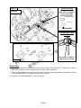
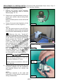
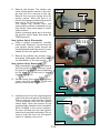
MOTORCYCLE / ATV DIVISION 4 - STROKE GS/GSX/GSX-R BULLETIN NO. 183 DATE: 6/6/2008 SAFETY RECALL CAMPAIGN #2A05 CERTAIN 2008 GSX1300RK8 MOTORCYCLES IGNITION SWITCH INSPECTION/REPLACEMENT SUBJECT: m o c . e RECALL CAMPAIGN - IGNITION SWITCH INSPECTION/ REPLACEMENT n o AFFECTED UNITS: CERTAIN 2008 GSX1300RK8 MOTORCYCLES Z a g r o . d REFERENCE: GSX1300R SERVICE MANUAL (PN 99500-39350-03E) ATTACHMENT: CUSTOMER LETTER us b a n y a l a e H k i B WHAT IS THE PROBLEM? This notice is sent to you in accordance with the requirements of the National Traffic and Motor Vehicle Safety Act. Suzuki Motor Corporation has determined that certain GSX1300RK8 motorcycles may have the ignition switch lead wire improperly routed. Handlebar movement can result in abnormal flexing and damage to the ignition switch lead wire. Damage to the ignition switch lead wire can result in intermittent or complete loss of electrical power, which can result in loss of lighting and/or stalling of the engine. This could result in a crash. STOP DELIVERY OF 2008 GSX1300RK8 MOTORCYCLES IMMEDIATELY DO NOT DELIVER an affected NEW or USED 2008 GSX1300RK8 motorcycle to a customer until you have completed, or verified completion of, the procedures in this bulletin. It is a violation of Federal law to deliver any new vehicle subject to a safety recall campaign under a sale or lease until the defect or noncompliance has been corrected. You must verify this on the Suzuki "Certificate of Vehicle Pre-Delivery" form, which is to be completed for all new and used vehicle sales. WHAT WILL SUZUKI DO? Suzuki is recalling affected units for inspection of the ignition switch lead wire routing. You will correctly reroute or replace the ignition switch lead wire portion of the ignition switch assembly. Instructions are provided in this bulletin for correct routing and replacement of the ignition switch lead wire to prevent failure. - 1/12- AFFECTED UNIT VIN RANGES: The VIN ranges of the affected GSX1300RK8 models are listed below. Confirmation of an affected unit can be checked on Suzuki Connect. Starting VIN JS1GX72A*82100020 JS1GX72A*82111267 JS1GX72A*82111546 JS1GX72A*82111700 JS1GX72A*82111726 JS1GX72A*82111755 JS1GX72A*82111759 JS1GX72A*82111766 JS1GX72A*82111775 JS1GX72A*82111785 JS1GX72A*82111945 JS1GX72A*82112169 JS1GX72A*82112171 Ending VIN JS1GX72A*82111031 n/a JS1GX72A*82111605 n/a JS1GX72A*82111753 JS1GX72A*82111756 n/a JS1GX72A*82111773 n/a JS1GX72A*82111943 JS1GX72A*82112167 n/a JS1GX72A*82112289 m o c . e n o Z a us g r o . d VERIFY THE UNIT REQUIRES THE RECALL REPAIR: Before performing the recall inspection to a unit, verify that the inspection needs to be done. There are two ways to identify a unit that has already been repaired. b a n y a l a e H k i B 1. Check the repair status by checking the Vehicle History in the Suzuki Connect Service Menu. If the repair needs to be performed to the motorcycle, you will see the message “CAMPAIGN NOT YET PERFORMED” displayed and the ignition switch lead wire routing will need to be inspected. Refer to the inspection procedure in this bulletin. 2. Inspect the right side of the frame head tube for an identification punch mark located at the beginning of the Vehicle Identification Number. If a punch mark is present the recall repair has already been performed. M Punch mark JS1GX72A382100028 WHAT YOUR DEALERSHIP WILL DO: Notify your staff. Contact your customers; please telephone all of your customers and inform them of the need to stop riding their motorcycles until the ignition switch lead wire inspection/replacement has been completed. NOTE: If your dealership has sold an affected GSX1300RK8 to a customer, but you have not yet submitted sales registration entry, send the sales information to American Suzuki AT ONCE. We will send the customer an owner notification letter when we receive the sales information from your dealership. Since only you know the identity of these customers, you must immediately notify these customers of the recall campaign. - 2/12- CUSTOMER NOTIFICATION: In the Safety Recall Campaign letter that will be mailed on June 10, 2008 (see attachment), customers are being advised to contact the Suzuki dealer where they purchased their affected unit to schedule an appointment to have the ignition switch lead wire inspected. As some customers may have moved to other communities since their motorcycle purchase, you may also receive calls from customers who purchased their Suzuki elsewhere. Once you are contacted by the owner of an affected unit, please arrange an appointment for a recall inspection. Also, advise your customers that the Safety Recall Campaign service will be performed at no cost to them for parts and labor. IMPORTANT: Successful completion of this safety recall campaign depends on your efforts. It is your responsibility to repair any affected GSX1300RK8 within the VIN range at no cost to the customer for recall service parts and labor. Incidental costs your customers may incur are not normally covered. However, if you have a customer with special needs, contact your Technical Service Manager (800/756-3251) to discuss possible solutions. m o c . e ORDERING PARTS FOR THE SAFETY RECALL CAMPAIGN: You will be responsible for ordering the ignition switch kit for any customer's motorcycle which had an incorrectly routed ignition switch lead wire. Order the switch kit using your normal parts ordering methods. New, unsold units at your dealership will not require a replacement ignition switch kit. Parts are currently available for this campaign. n o Z a g r o . d Ignition Switch Set PN 99103-11237 Dealer Cost-$85.03 Description Qty Note 1 Ignition Switch 1 2 Screws 2 Mounted on Ignition Switch 3 Bolt, M8 2 Torx head, Pre-coated bolt 4 Cap 2 us b a n y a l a e H k i B SPECIAL TOOL AUTO-SHIPMENT The special tool needed to disassemble the lock cylinder assembly will be auto-shipped separately at no cost to your dealership during the week of June 9, 2008. IGNITION SWITCH LEAD WIRE INSPECTION, REROUTING OR REPLACEMENT STEPS New Unsold Unit (Dealer Inventory) Inspect Routing (page 4) OK Punch Mark VIN (page 8) Incorrect Reroute (page 5) OK Punch Mark VIN (page 8) OK Punch Mark VIN (page 8) Customer Unit (Sold) / Dealer Demo Unit Inspect Routing (page 4) OK Incorrect Punch Mark VIN (page 8) Replace Ignition Switch (page 6) - 3/12- INSPECT ROUTING 1. Remove the upper and lower meter panels (refer to Service Manual page 9D-15). 2. Check if the ignition switch lead wire is clamped and routed correctly. Incorrect positions are shown in Figures 1 and 2. Correct routing and clamping is shown in Figures 3 and 4 on page 5. Figure 1 Incorrect Position Incorrect Gray Tape Position n o Z a Figure 2 Incorrect Routing m o c . e us Gray tape is not visible on both sides of clamp -orGray tape is not positioned beneath clamp b a n y a l a e H k i B g r o . d Incorrect Routing Ignition switch harness is routed behind the right switch harness. 900 Cowling Brace Side § 900 900 = Ignition Switch Lead Wire - 4/12- Figure 3 Correct Routing The ignition switch lead wire is routed in front of the right switch lead wire. Correct ª Front side Correct Gray Tape Location m o c . e n o Correct Correct 900 us Z a b a n y a l a e H k i B g r o . d Figure 4 900 Gray tape is visible on both sides of clamp. REROUTING 1. Reroute the ignition switch lead wire correctly (Figure 3 and Figure 4). The ignition switch lead wire should not be covered by the other wire harnesses. 2. Turn the handlebars back and forth to verify that the steering operates smoothly and the wiring harness does not become kinked or pinched. 3. Proceed to PUNCH MARK AT VIN on page 8. - 5/12- REPLACEMENT OF IGNITION SWITCH (Customer Sold Units/Dealer Demo Units- Only If Inspection Shows Incorrect Routing And Unit Has Been Ridden) New Ignition Switch Disassembly 1. Remove the ignition switch assembly from the motorcycle (refer to Service Manual page 1H-12). 2. Remove the two black plastic covers to access the cylinder cap mounting bolts (Figure 5). Note: The black plastic covers will not be reused. 3. Secure the mount area (bottom) of the ignition switch in a vise (Figure 6). Figure 5 m o c . e NOTE: Turn the ignition switch to the OFF position and remove the key from the ignition switch before disassembling the switch. \ Remove the two "break-off" screws from the ignition switch using the special screwdriver. Set the stepped end of the sleeve on the special screwdriver facing toward the "break-off" screws (Figure 7). Strike the special screwdriver 5 to 7 times with a hammer to produce a deep enough groove on the screw head for the screwdriver to work properly (Figure 6). Pay attention not to hit other parts with the hammer. Turn to remove the "break-off" screws in a counterclockwise direction. If the groove becomes damaged, make another groove at a 90o angle to the original groove. n o Z a us g r o . d b a n y a l a e H k i B Figure 6 Figure 7 When striking an object with a hammer parts can fly up, hitting you in the eyes and cause blindness or injury. Cylinder Cap Always wear eye protection when using a hammer. 4. Remove the ignition switch from the vise and hold it upright over the workbench and carefully remove the cylinder cap (Figure 8). NOTE: Pay close attention to the order and orientation of the ignition switch parts during disassembly. Figure 8 - 6/12- 5. Remove the shutter. The shutter may come off the ignition switch in the cylinder cap, but is not secured to the cap. Remove the rotor and spring from the ignition switch. When the rotor is removed, the spring may be attached to the rotor, but it will not be secured. The cylinder cap, shutter, rotor, and spring will be used for reassembly of the new switch. Keep these parts in a safe, clean location. Attach a warranty parts tag to the original ignition switch body and retain for TSM inspection. Figure 9 Shutter Spring New Ignition Switch Disassembly 8513 A 6. Using a philips screwdriver, carefully remove the "break-off" screws from the new ignition switch (these screws are hand-tightened) and keep them for reassembly of the new ignition switch. 7. Remove the cylinder cap, shutter, rotor, and spring. These parts will not be reused for reassembly of the new switch. m o c . e n o Z a us New Ignition Switch Reassembly Rotor g r o . d Figure 10 b a n y a l a e H k i B Begin reassembly using the main body of the new ignition switch. The new (recall kit) ignition switch body can be identified by the letter "A" at the end of the lot number (Figure 10). 8. Set the spring from the original ignition switch onto the projection in the new ignition switch body (Figure 11). Spring Figure 11 9. Install the rotor from the original ignition switch into the new ignition switch body. There is only one correct position (Figure 12) to install the rotor into the ignition switch body. Note the position of the tumbler plates when the rotor is installed. When installed in the correct position, the rotor will drop into the new ignition switch body smoothly and easily. Do not force or push the rotor into the ignition switch or damage may occur. Tumbler Plates Figure 12 - 7/12- 10. Place the shutter from the original ignition switch on the rotor, aligning and placing the projections into the hollows (Figure 13). The shutter can be aligned one of two ways 180o apart. Either way is correct. 11. Place the cylinder cap over the key cylinder and hold it firmly in position. Insert the ignition key and test the rotation of the rotor. If the rotor does not turn smoothly, remove the cap and check the assembly, making any necessary corrections. Repeat the procedure until the rotor turns smoothly when using the key. 12. Secure the cylinder cap with the breakoff screws. Tighten the screws evenly until the screw heads break off (Figure 14). Install the plastic caps (provided in the kit) on the cylinder cap over the break-off screws. Install the ignition switch assembly (refer to Service Manual page 1H-12). Be certain to use the pre-coated bolts provided in the recall kit when installing the new ignition switch. Switch Mount Bolt: " Ignition . 13 N m (1.3 kgf-m, 9.5 lb-ft) Refer to Figure 3 and 4 on page 5 for correct routing of the ignition switch lead wire. Projections Figure 13 m o c . e n o Z a us Hollows g r o . d Figure 14 b a n y a l a e H k i B 13. Turn the handlebars back and forth to verify that the steering operates smoothly and the wiring harness does not get kinked or pinched. PUNCH MARK AT VIN 1. After the inspection, rerouting, or replacement procedure is complete be certain to place an identification punch mark on the frame at the beginning of the Vehicle Identification Number (located at the right side of the frame head tube) as illustrated on page 2. - 8/12- WARRANTY REIMBURSEMENT & CLAIM INFORMATION: Submit a warranty claim for each recall campaign service immediately upon completion of the repair. This campaign requires you to file a warranty claim using the following information. Short Form Claim: Use the Short Form Claim for new, and customer owned units that require ignition switch lead wire inspection and/or re-routing. Labor time is 0.3 hours. RECALL CAMPAIGN IGNITION SWITCH LEAD WIRE INSPECTION, REROUTE Short Form Instructions GENERAL CLAIM NUMBER: XXXXX,X (Dealer enters number) ENTRY TYPE: Model, Frame or Control Sequence (Dealer Chooses) MODEL: GSX1300RK8 FRAME: X821XXXXX REPAIR DATE: Enter date of repair MILEAGE: Enter mileage on unit CAMPAIGN NUMBER: 2A05 Long Form Claim: Use the Long Form Claim for customer owned units requiring ignition switch assembly replacement or for units with additional time or parts required as approved by Tech-Line. Labor time is 1.3 hours. m o c . e n o Z a g r o . d RECALL CAMPAIGN IGNITION SWITCH LEAD WIRE INSPECTION AND REPLACEMENT Long Form Instructions GENERAL CLAIM NUMBER: XXXXX,X (Dealer enters number) ENTRY TYPE: Model, Frame or Control Sequence (Dealer Chooses) MODEL: GSX1300RK8 FRAME: X821XXXXX REPAIR DATE: Enter date of repair MILEAGE: Enter mileage on unit CAMPAIGN NUMBER: 2A05 LABOR HOURS: 1.3 hrs PARTS REPLACEMENT PART NUMBER: 99103-11237 QTY: 1 FAILURE DESCRIPTION DESCRIPTION OF FAILURE: Replace Ignition Switch Assembly per Service Bulletin GS-GSX-GSXR-GSF 183 SUBLET SUBLET AMOUNT: as approved by TECH-LINE NOTE: Do not use the "$" when entering an amount SUBLET REFERENCE NUMBER: 2A05 SUBLET REPAIR DESCRIPTION: us b a n y a l a e H k i B Suzuki Connect Long Form warranty claim entries with additional parts or labor require a prior authorization (PAS) code from TECH-LINE or your Technical Service Manager, or the Suzuki Connect system will not accept the claim. - 9/12- CUSTOMER SATISFACTION: We understand and apologize for any inconvenience this recall campaign may cause you or your customers. Thank you for your cooperation in conducting this very important campaign for your customers' safety and satisfaction. Only your conscientious action at the dealership level can lead to a successful campaign conclusion. Please remind your staff to be sympathetic and sensitive to your customers' feelings. Please extend Suzuki's apologies for any inconvenience this recall campaign may cause them. m o c . e n o Z a us g r o . d b a n y a l a e H k i B AFFECTED DEPARTMENTS: The following departments in your dealership should be notified of this information: ⌧ Management ⌧ Service ⌧ Warranty ⌧ Sales American Suzuki Motor Corporation Technical Service Department Motorcycle / ATV - 10/12- ⌧ Parts ⌧ Accessories CUSTOMER NOTIFICATION LETTER - Page One of Two June 10, 2008 SAFETY RECALL CAMPAIGN #2A05 CERTAIN 2008 GSX1300RK8 (HAYABUSA) MOTORCYCLES IGNITION SWITCH INSPECTION/REPLACEMENT m o c . e Dear Suzuki Owner: This notice is sent to you in accordance with the requirements of the National Traffic and Motor Vehicle Safety Act. n o What is the reason for this notice? Suzuki Motor Corporation has decided that a defect which relates to motor vehicle safety exists in certain 2008 model year GSX1300RK8 motorcycles. Suzuki Motor Corporation is conducting a voluntary Safety Recall Campaign. According to our records, you are the owner of one of these motorcycles. Z a us g r o . d b a n y a l a e H k i B What is the problem? Suzuki Motor Corporation has determined that certain GSX1300RK8 motorcycles may have the ignition switch lead wire improperly routed. Handlebar movement can result in abnormal flexing and damage to the ignition switch lead wire. Damage to the ignition switch lead wire can result in intermittent or complete loss of electrical power, which can result in loss of lighting and/or stalling of the engine. This could result in a crash. To minimize the risk of injury or death, we recommend that you do not ride, or allow anyone else to ride, your 2008 model year GSX1300RK8 (Hayabusa) until your motorcycle has been repaired by your Suzuki dealer. Suzuki strongly recommends that you do not ride your affected 2008 GSX1300RK8 (Hayabusa) motorcycle until the ignition switch inspection/replacement has been completed What is Suzuki doing to solve the problem? The repair consists of thoroughly inspecting the ignition switch lead wire routing. If the ignition switch lead wire is not routed or clamped properly, Suzuki will replace the ignition switch/lead wire assembly. Your original lock set will be installed onto the new ignition switch/lead wire assembly so that your original key will operate the ignition switch. Repair time is approximately 1.3 hours and will be performed at no cost to you for parts or labor. How do I receive the fastest possible service? Suzuki understands that your riding time is precious. Our suggestion is to work closely with your authorized dealer to get the recall service scheduled and performed on your motorcycle as quickly as possible. Schedule an appointment for the recall service to be performed. Parts are currently available. It will be necessary for your dealer to order the parts. It may be necessary to leave your motorcycle with the dealer overnight, so check with your dealer. - 11/12- CUSTOMER NOTIFICATION LETTER - Page Two of Two How do I receive the fastest possible service (cont.) When you pick up your repaired motorcycle, please allow a few extra minutes for your dealer to prepare and complete the necessary warranty paperwork with you. If you have special circumstances, discuss them with your Suzuki dealer. Suzuki understands that some customers may have difficult circumstances to overcome in bringing their motorcycle to the dealership for repair. We have asked your Suzuki dealer to work closely and flexibly with you to arrange alternative, but reasonable solutions for your special requests. Please remember however, that each dealership has its own limitations in providing special assistance due to staff size, available time and dealership location. Your dealer can also consult with Suzuki on other alternatives. Questions & Answers Your Suzuki dealer has been provided specific and complete instructions regarding this recall service. Please call your dealer if you have any questions. Your local Suzuki dealer can provide the fastest responses to your questions or concerns about the recall service. Your dealer can also contact Suzuki on your behalf if you have a unique question or concern. If you have difficulty having the recall service performed on your motorcycle you may contact the American Suzuki Customer Service Department for assistance at 1-714-572-1490. You will need to have your Vehicle Identification Number ready when calling. m o c . e If you believe that (1) Suzuki or your Suzuki dealer has failed to or is unable to perform the recall service without charge, or (2) you believe Suzuki has failed to or is unable to perform the recall procedure to your vehicle within 60 days after you first brought your vehicle to your Suzuki dealer after June 10, 2008 you may submit a complaint to the Administrator, National Highway Traffic Safety Administration, 1200 New Jersey Ave, S.E., West Building, Washington, D.C. 20590 or call the toll free Vehicle Safety Hotline at 1-888-327-4236 (TTY: 1-800-424-9153); or go to http://www.safercar.gov. Z a n o g r o . d Locating an alternate dealer Suzuki dealers can be located on the internet at www.suzukicycles.com or by calling 1-800-828-7433. us b a n y a l a e H k i B Customer Reimbursement If your motorcycle is included in the recall and you have paid for the repair or replacement of the ignition switch, you may be eligible for full or partial reimbursement. Please note the following for which Suzuki may exclude reimbursement: • Only repairs that are the subject of the safety recall are reimbursable. Additional expenses such as towing, rental, accommodations, damage repairs, etc will not be reimbursed. • Reimbursement may be limited to suggested list price on parts and the Suzuki published flat rate time allowance. • An owner will not be eligible for reimbursement if the expenses for repairs are incurred more than 10 days after the date of the last owner notification letter sent by Suzuki. • Reimbursement claims may also be excluded when you do not submit adequate documentation. Your authorized Suzuki dealer will request an original or copy of your receipt for the recall repair or replacement, and your owner notification letter. To obtain information or request reimbursement, contact your Suzuki dealer or the American Suzuki Motor Corporation, Motorcycle Customer Service Department, PO Box 1100, Brea, CA 92822-1100, or call 1-714- 572-1490. You will need to have your Vehicle Identification Number ready when calling. We thank you for your prompt attention to completing this recall service on your Suzuki motorcycle. We apologize for any inconvenience this campaign causes you. Your safety, satisfaction and riding enjoyment are priorities for Suzuki. Sincerely, American Suzuki Motor Corporation - 12/12-