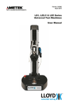
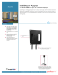
1
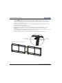
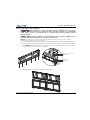
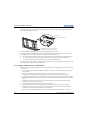
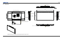
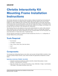
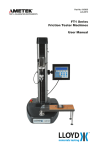
P100 Pedestal and F100 Frame Installation Manual 020-100734-02 P100 Pedestal and F100 Frame Installation Manual 020-100734-02 NOTICES COPYRIGHT AND TRADEMARKS © 2011 Christie Digital Systems USA, Inc. - All rights reserved. All brand names and product names are trademarks, registered trademarks or trade names of their respective holders. GENERAL Every effort has been made to ensure accuracy, however in some cases changes in the products or availability could occur which may not be reflected in this document. Christie reserves the right to make changes to specifications at any time without notice. Performance specifications are typical, but may vary depending on conditions beyond Christie's control such as maintenance of the product in proper working conditions. Performance specifications are based on information available at the time of printing. Christie makes no warranty of any kind with regard to this material, including, but not limited to, implied warranties of fitness for a particular purpose. Christie will not be liable for errors contained herein or for incidental or consequential damages in connection with the performance or use of this material. The product is designed and manufactured with high-quality materials and components that can be recycled and reused. This symbol means that electrical and electronic equipment, at their end-of-life, should be disposed of separately from regular waste. Please dispose of the product appropriately and according to local regulations. In the European Union, there are separate collection systems for used electrical and electronic products. Please help us to conserve the environment we live in! GENERAL WARRANTY STATEMENTS For complete information about Christie’s limited warranty, please contact your Christie dealer. In addition to the other limitations that may be specified in Christie’s limited warranty, the warranty does not cover: a. Damage occurring during shipment, in either direction. b. Damage caused by misuse, improper power source, accident, fire, flood, lightning, earthquake or other natural disaster. c. Damage caused by improper installation/alignment, or by product modification, if by other than a Christie authorized repair service provider. d. Problems caused by combination of the equipment with non-Christie equipment, such as distribution systems, cameras, video tape recorders, etc., or use of the equipment with any non-Christie interface device. e. Failure due to normal wear and tear. f. Warranty does not cover image retention. PREVENTATIVE MAINTENANCE Preventative maintenance is an important part of the continued and proper operation of your product. Please see the Service Manual for specific maintenance items as they relate to your product. Failure to perform maintenance as required, and in accordance with the maintenance schedule specified by Christie, will void the warranty. Table of Contents 1: Introduction 1.1 Using this Manual........................................................................................................................1-1 1.2 Labels and Marking .....................................................................................................................1-1 1.3 Typographical Notations .............................................................................................................1-1 1.4 Safety Warnings and Guidelines .................................................................................................1-2 1.4.1 Stacking Limitations ............................................................................................................1-2 1.4.2 Using Christie P100 Pedestals .............................................................................................1-2 1.4.3 External Support ..................................................................................................................1-2 1.4.4 Lifting LCD Panels..............................................................................................................1-2 1.4.5 Airflow Considerations........................................................................................................1-2 1.5 Contact Information.....................................................................................................................1-2 2: Installation and Setup 2.1 Components .................................................................................................................................2-1 2.1.1 For P100 Pedestals (Hardware Kit P/N: 000-102657-xx) ...................................................2-1 2.1.2 For F100 Frames (Hardware Kit P/N: 000-102673-xx) ......................................................2-2 2.1.3 For LCD Video Wall Mounts and LCD Panels...................................................................2-2 2.2 Kits Required ...............................................................................................................................2-2 2.3 Tools and Hardware Required .....................................................................................................2-2 2.4 Service and Support.....................................................................................................................2-2 2.5 Installation ...................................................................................................................................2-3 2.5.1 Assemble the Pedestals........................................................................................................2-3 2.5.2 Install Frames onto Pedestals...............................................................................................2-5 2.5.3 Adding Additional Rows of F100 Frames...........................................................................2-6 2.5.4 Install Video Wall Mount onto Frame.................................................................................2-7 2.5.5 Install FHD551-X LCD Panel .............................................................................................2-7 2.5.6 Apply Permanent External Support .....................................................................................2-7 2.5.7 Connect Sources ..................................................................................................................2-8 2.5.8 Optional: Install Trim ..........................................................................................................2-8 2.5.9 Optional: Install Bracket Extension Hook ...........................................................................2-8 A: Mechanical Drawings A.1 LCD Panel ..................................................................................................................................A-1 A.2 2x2 Configuration of Pedestal, Frame and LCD Panel ..............................................................A-2 A.3 Attaching Pedestal and Frame ....................................................................................................A-3 Pedestal and Frame Installation Manual 020-100734-02 Rev. 1 i 1 Introduction Every effort has been made to ensure the information in this document is accurate and reliable; however, due to constant research the information in this document is subject to change without notice. 1.1 Using this Manual To prevent physical injury or equipment damage it is important Section 2 Installation and Setup is read in its entirety before installing this product. This manual provides technical information for assisting qualified service technicians in the installation of the P100 Pedestal and F100 Frame. 1.2 Labels and Marking Observe and follow any warnings and instructions marked on the projector. Danger symbols indicate a hazardous situation which, if not avoided, will result in death or serious injury. This signal word is to be limited to the most extreme situations. Warning symbols indicate a hazardous situation which, if not avoided, could result in death or serious injury. Caution symbols indicate a hazardous situation which, if not avoided, could result in minor or moderate injury. NOTICE! Addresses practices not related to personal injury. 1.3 Typographical Notations The following notations are used throughout this manual: • References to specific areas of the document appear italicized and underlined. When viewed online the text appears in blue indicating a direct link to that section. For example, Section 1 Introduction. • References to other documents appear italicized and bold, such as Service Manual. • References to software menus and available options appear bold, such as Main menu, Preferences. • User input or messages that appear on screen, in status display units or other control modules appear in Courier font. For example. “No Signal Present”, Login: christiedigital. • Error codes, LED status appear in bold, e.g. LP, A1 etc. • Operational states of modules appear capitalized, such as power ON/OFF. Pedestal and Frame Installation Manual 020-100734-02 Rev. 1 (11-2011) 1-1 Section 1: Introduction 1.4 Safety Warnings and Guidelines Please read the following warnings before commencing installation to ensure the safety of those working at the installation site. 1.4.1 Stacking Limitations Do not stack more than 6 F100 Frames when using the approved P100 Pedestals. Stacking the frames higher than the recommended limit increases the possibility of the display wall becoming unstable and unsafe, and also increases the chance that the pedestals may buckle from the extra weight. 1.4.2 Using Christie P100 Pedestals It is strongly recommended that the P100 Pedestals are used with both the F100 Frames and the FHD551-X LCD Panels. Installers must ensure that the LCD panels are mounted to or within a secure structure that can adequately support the weight of the stacked panels. If a display wall is built with any other platform, the installer must ensure that the platform is stable and can support the weight of the frames and LCD panels (to their stacking limits). Ensure that pedestals are level before stacking the F100 Frames and LCD panels. See also 1.4.3 External Support, on page 1-2. 1.4.3 External Support Stacked pedestals, frames and LCD panels can tip over and cause severe injury or damage when not properly secured. The display wall must be supported during and after installation to a structurally sound surface, such as a permanent wall or an installer-approved free-standing external support structure. The P100 Pedestals, F100 Frames and LCD panels must be stacked onto a level surface. If stacked on a nonlevel or inclined surface, there is an increased risk that the structure (even when mounted in secured or freestanding external structures) could tip over and cause serious injury or damage. It is strongly recommended that P100 Pedestals be used to create the platform for a display wall incorporating the F100 Frames and FHD551-X LCD Panels. 1.4.4 Lifting LCD Panels Lift equipment MUST be used to lift LCD panels into position on higher rows. A crew of two can lift an LCD panel into position on the first row. 1.4.5 Airflow Considerations It is important that the room temperature measured all around the display wall is no greater than the operating temperature, which is min. 5°C (41°F) ~ max. 40°C (104°F). It is up to the installer to determine, based on their installation, how much open area is required around the display wall for adequate airflow. 1.5 Contact Information For current contact information, refer to www.christiedigital.com. 1-2 Pedestal and Frame Installation Manual 020-100734-02 Rev. 1 (11-2011) 2 Installation and Setup Installation of a display wall for the FHD551-X LCD panels should be undertaken only by qualified installers with the requisite training, knowledge and skill to properly install the system. The following instructions outline how to install a display wall for the FHD551-X LCD panel, as a single or multi unit system – using the P100 pedestal and F100 frame. Additional important information relating to the display wall can be found in the ML10/MP10 40-65” LCD Video Wall Mount Instruction Sheet (P/N: 020100726-xx) and the LCD Panel FHD551-X User Manual (P/N: 020-100713-xx). The installer should be familiar with this information before starting the installation. These instructions are intended to provide qualified installers with step-by-step installation information; however, circumstances and conditions may vary from one installation site to another and the installer has the sole and final responsibility for ensuring that the system is installed with due regard for all relevant safety considerations. Installation steps are described in sequence and each step must be completed before moving on to the next. 2.1 Components All major components required to assemble a complete display wall are packaged and shipped separately to the installation site. This includes the LCD panels, P100 Pedestals, F100 Frames and the LCD video wall mounts. Each component comes with the hardware required for installation. Check the contents of your shipment against the list below to make sure that you have all the necessary hardware. NOTE: Trained service technicians are available to diagnose and correct system-related problems. If you encounter any problems during the setup and installation of your system, contact the authorized dealer or Christie Partner from whom the system was purchased. 2.1.1 For P100 Pedestals (Hardware Kit P/N: 000-102657-xx) • • • • • • • • (2) Panel caps (16) Flat washers (8) M6 hex nuts ɸ6.5 (8) M6 hex head bolt (8) Lock washers (8) M8 socket head cap screws (for securing frame to pedestal) (16) Flat washers ɸ8.4 (8) M8 hex nuts (for securing frame to pedestal) Pedestal and Frame Installation Manual 020-100734-02 Rev. 1 (11-2011) 2-1 Section 2: Installation and Setup 2.1.2 For F100 Frames (Hardware Kit P/N: 000-102673-xx) • • • • • • • • (2) Bracket extension hooks (4) Flat washers ɸ4.3 (4) M4 hex nuts (4) Flat washers ɸ6.4 (10) Flat washers ɸ8.4 (10) M8 socket head cap screws (4) M6 socket head cap screws (2) Grommets 2.1.3 For LCD Video Wall Mounts and LCD Panels Refer to the ML10/MP10 40-65” LCD Video Wall Mount Instruction Sheet (P/N: 020-100726-xx) and the LCD Panel FHD551-X User Manual (P/N: 020-100713-xx). 2.2 Kits Required • P100 LCD Pedestal (P/N: 135-106108-xx) • F100 LCD Frame (P/N: 135-105107-xx) • FHD551-X LCD Panel (P/N: 135-001102-xx) • Optional: LCD Frame Trim 8ft (P/N 135-108100-xx) 2.3 Tools and Hardware Required • • • • • • • • 2.4 Level Phillips screwdriver 5mm allen key for attaching P100 Pedestals 6mm ball driver metric screwdriver for attaching F100 Frames 24mm open ended/adjustable wrench for tightening locknut on pedestal feet 7mm open ended wrench for fastening extension hook 2x 10mm open ended wrench for fastening pedestal to pedestal 13mm open ended wrench for fastening frame to pedestal Service and Support Trained service technicians are available to diagnose and correct system-related problems. If you encounter any problems during the setup and installation of your system, contact the authorized dealer or Christie Partner from whom the system was purchased. 2-2 Pedestal and Frame Installation Manual 020-100734-02 Rev. 1 (11-2011) Section 2: Installation and Setup 2.5 Installation 2.5.1 Assemble the Pedestals Once the pedestal platform is constructed it is essential an external support is constructed before adding the frames, video wall mounts and LCD Panels to prevent the display from tipping and causing serious injuries to those at the installation site. NOTICE! Depending on the size of the wall, assemble the platform beginning with the center pedestal, working outwards to the end of each row. 1. Slide 2 pedestals together aligning the front and rear edges. 2. Using a level, adjust the 3 pedestal feet by rotating them until the 2 pedestals are level on all sides and with each other. Use a 24mm open ended/adjustable wrench to tighten the lock nut on the feet once the required adjustment is made. Tighten lock nut once adjustments are made 3. Inspect the inside corners of the pedestal to confirm that the pedestal feet remain fully engaged in the pedestal. If you cannot see any threads at the top of the corner bracket where the foot is installed, then you have over-extended the pedestal foot and must correct this before moving on. 4. Using a phillips screwdriver, loosen the 8 screws on the rear pedestal skin. Slide the rear skin up and out to access the mounting points on the pedestal. Pedestal and Frame Installation Manual 020-100734-02 Rev. 1 (11-2011) 2-3 Section 2: Installation and Setup 5. Loosely fasten the 2 pedestals together using 4 M6 hex nuts, 4 M6 hex head bolts, 8 flat washers and 4 lock washers. NOTES: 1) Keeping the hardware a little loose at this point will allow you to tweak the alignment between pedestals as more are added to the platform. 2) Do not completely tighten the hardware on the pedestal until the first row of frames are installed. For more information, refer to 2.5.2 Install Frames onto Pedestals, on page 2-5. 6. Slide the next pedestal into position and, using a level, adjust the height until the pedestal becomes level with the pedestals already in the row. 7. Repeat steps 1 to 5, for each additional pedestal. 8. Verify that the entire platform structure is level and that all rear edges between pedestals are flush. NOTICE: Apply downward pressure on the pedestal to ensure that the feet are flat to the floor. 9. Do not completely tighten the hardware on the pedestal until the first row of frames are installed. For more information, refer to 2.5.2 Install Frames onto Pedestals, on page 2-5. 10. Once the pedestal assembly is constructed snap the panel caps into place (see image below). M6 hex nut Lock washer M6 hex head bolts Flat washer NOTE: Front skin not shown in image for clarity. Insert panel caps here (1 on each side) 2-4 Pedestal and Frame Installation Manual 020-100734-02 Rev. 1 (11-2011) Section 2: Installation and Setup 2.5.2 Install Frames onto Pedestals Stacked LCD panels can tip over and cause injury or damage when not properly secured. The display wall must be supported during and after installation to a structurally sound surface, such as a permanent wall or an installer-approved free-standing external support structure. Lift equipment MUST be used to lift LCD panels into position on higher rows. A crew of two can lift an LCD panel into position on the first row. NOTICE: Depending on the size of the wall, assemble the frames starting at the center of the pedestal assemble, working outwards to the end of each row. 1. Position the first frame so that the 6 mounting points of the frame line up with the points on the pedestal. 2. Loosely fasten the frame to the pedestal using (6) M8 socket head cap screws, 12 washers and (6) M8 hex nuts. NOTES: 1) Keeping the hardware a little loose at this point will allow you to tweak the alignment between frames as more are added to the platform. M8 socket head cap screw Flat washer 6 5 Flat washer M8 hex nut 4 3 2 1 3. Place the next frame onto the next pedestal and repeat step 1. Pedestal and Frame Installation Manual 020-100734-02 Rev. 1 (11-2011) 2-5 Section 2: Installation and Setup 4. Using (4) M8 socket head cap screws and (4) flat washers (ɸ8.4), secure the 2 frames to one another using the 4 mounting points, as shown below. Hand tighten the hardware to allow small adjustments while the other frames are added to the row. Flat washer M8 socket head cap screw Insert grommet here (1 on each side) *repeat for every row of frames 5. Check the alignment between each frame and make adjustments, as required. 6. Completely tighten the hardware between the frames and pedestals before adding the next row of frames. Some adjustment of the pedestal feet may be required to achieve a level row. a. Use a 5mm allen key and two 10mm open ended wrenches to tighten the hardware on the pedestals. b. Use a 13mm open ended wrench to tighten the hardware securing the frames to the pedestals. c. Use a 6mm ball driver to tighten the hardware securing the frames together. 7. Snap grommets into the cutouts of the frames on each end of the row. These grommets ensure the cables do not rub against the metal cutout (see image above). 2.5.3 Adding Additional Rows of F100 Frames 1. Add the second row, beginning with the center and working outward. Complete these steps for each frame in the next row. a. Using safe and approved lifting methods, install the next frame over the lower frame, approaching it from the back. b. Once the top frame is resting on the lower frame, slide it forward until it is in position. c. Align the top and bottom frames until all edges are flush and the mounting holes are aligned. d. Using 6 M8 socket head cap screws and 6 flat washers (ɸ8.4) secure the upper frame to the one below. Hand tighten the hardware at this point to allow for small adjustments as the other frames are added to the row. e. Position the next frame in the row. Using 4 M8 socket head cap screws and 4 flat washers (ɸ8.4), secure the frame to the one adjacent to it. f. Check alignment between each frame and adjust, as required. g. Tighten all hardware between the top and bottom frames before adding the next row of frames. h. Snap grommets into the cutouts of the frames on each end of the row. These grommets ensure the cables do not rub against the metal cutout (see image above). i. Repeat the above steps to add additional rows of frames until the desired installation is complete. 2-6 Pedestal and Frame Installation Manual 020-100734-02 Rev. 1 (11-2011) Section 2: Installation and Setup 2.5.4 Install Video Wall Mount onto Frame For a detailed overview, refer to the ML10/MP10 40-65” LCD Video Wall Mount Instruction Sheet (P/N: 020-100726-xx) and the LCD Panel FHD551-X User Manual (P/N: 020-100713-xx). 2.5.5 Install FHD551-X LCD Panel For a detailed overview, refer to the ML10/MP10 40-65” LCD Video Wall Mount Instruction Sheet (P/N: 020-100726-xx) and the LCD Panel FHD551-X User Manual (P/N: 020-100713-xx). 2.5.6 Apply Permanent External Support External support for a display wall must be designed and implemented by a qualified installer and must comply to local area safety standards. All display walls must have permanent external supports. The FHD551-X LCD panel display wall requires external support regardless of its overall height. Reinforcing the structure prevents the wall from tipping due to unforeseen circumstances. When designing external support for a display wall consider: • Local building codes for specific requirements. • Size of the installation (number of LCD panels being stacked). • Physical characteristics of the installation (including weight, center of gravity, mounting hole location). See Section A Mechanical Drawings for technical information on display wall components. • Type of material being considered for external support. • Strength and stability of the vertical or horizontal surface. • Required number of external supports. The illustration below depicts 2 possible external support methods for a display wall. Consider your options and choose the method that best supports your specific installation. CAUTION! The natural frequency of support is dependant on the size of the wall and should be determined by a qualified installer. Example of Ceiling Mount Support (Shown, threaded rods installed into ceiling to support 2x2 wall) Pedestal and Frame Installation Manual 020-100734-02 Rev. 1 (11-2011) Example of Wall Mount Support (Shown, bars installed into back wall to support 2x2 wall) 2-7 Section 2: Installation and Setup 2.5.7 Connect Sources A variety of external sources can be connected to the connection panel on the LCD panel. Properly routing the cables from 1 LCD panel to another in the display wall will keep them from becoming tangled. For a detailed overview, refer to the ML10/MP10 40-65” LCD Video Wall Mount Instruction Sheet (P/N: 020-100726-xx) and the LCD Panel FHD551-X User Manual (P/N: 020-100713-xx). 2.5.8 Optional: Install Trim As an optional feature, trim in the form of 8ft (2.4m) magnetic strips can be applied to the sides of the display. Each strip covers up to 3 frames in height. 2.5.9 Optional: Install Bracket Extension Hook To easily release individual panels installed into a display wall it is recommended the bracket extension hooks, provided with the frame assembly, are installed. To install, thread an M4 nut and flat washer onto the hook, insert it into the video wall mount, as shown in the illustration below. Thread another flat washer and M4 nut onto the hook to secure it. Use a 7mm open ended wrench to completely tighten the hardware. Hardware Configuration Front View Back View 2-8 Pedestal and Frame Installation Manual 020-100734-02 Rev. 1 (11-2011) A Mechanical Drawings Pedestal and Frame Installation Manual 020-100734-02 Rev. 1 (11-2011) A-1 Appendix A: Mechanical Drawings A.1 LCD Panel DO NOT obstruct the air flow. 2.12 53.90 47.85 1215.30 M8 x 4 Mounting Holes, Length of screw engagement: 10mm (min), 15mm (max) Display Port HDMI 1 HDMI 2 PC Audio In DO NOT obstruct the air flow. IR Extender DVI-D In VGA In DVI-D Out Line Out VGA Out S-Video 15.75 400.00 Power Switch (Rocker Type) Video Out 27.01 686.10 Comp Audio 23.59 599.30 Video In L Video/S-V Audio Power Connection R Video/S-V Audio RS232 In RS485 In RS485 Out NOTE: Handles are hidden in this view for clarity. Exhaust & power supply location DO NOT obstruct the air flow. This side UP in landscape mode This side UP in portrait mode 23.62 600.00 Handle x4 locations DO NOT obstruct the air flow. NOTE: Illustrations shown as third angle projection. Not to scale. Pedestal and Frame Installation Manual 020-100734-02 Rev. 1 (11/11) A-1 Appendix A: Mechanical Drawings A.2 2x2 Configuration of Pedestal, Frame and LCD Panel Minimum ‘Image to Image’ Gap Dimension 2x2 Configuration of Pedestal, Frame & LCD Panel with Extended Mount for Service .22 5.70 Pull Bracket Extension Hook on either side of panel to extend the display carriage .22 5.70 B Pull strap to incline panel A 24° Detail B 90.02 2287 [11.57] 294 95.69 2431 Panel Extended Out for Service 9.23 235 Dimensions shown here is when ‘corner adjustment knob’ in the mount is extended to 14mm (0.5”) from its home position. LCD Panel P/N: 135-001102 Frame P/N: 135-105107 Pedestal P/N: 135-106108 General Notes: 1. Refer to ML10/MP10 55” Spacer Kit Instruction Sheet (P/N: 020-100728-xx) for wall mount applications. 2. Mounts, frame, pedestal shown here are for landscape orientation. 3. Maximum stack height is 6 panels. 4. Approximate weight of panel with adapter plate and display carriage - 52 kg (114.6 lbs). 5. Approximate weight of frame - 16.7 kg (36.8 lbs). 6. Approximate weight of pedestal - 24.8 kg (54.7 lbs). NOTE: Illustrations shown as third angle projection. Not to scale. A-2 Pedestal and Frame Installation Manual 020-100734-02 Rev. 1 (11/11) Appendix A: Mechanical Drawings A.3 Attaching Pedestal and Frame 16.44 417.66 13.78 350.00 General Notes: 1. Views shown here are for pedestal and frame assembly for landscape orientation. 2. Maximum adjustment possible using height adjustment knob is 25mm (1”). 3. Maximum range of adjustment on threaded foot along Y-axis is ±50mm (2”). 2.91 73.96 33.88 861 Fasten to wall (6x) Max torque 9Nm (80lb.in) 16.00 406.4 16.00 406.4 1.39 35 10x M8 2.96 75.16 LCD Panel with Adapter Plate Height adjustment knob-right 22.08 560.8 Fasten frame with max torque 15Nm (133lb.in) when used with lubricated screws 23.69 601.70 Corner adjustment knob-left Height adjustment knob-left 62.97 1600 4x .28 7.00 24.61 625.0 Corner adjustment knob-right .31 800 15.75 400 Secure adjacent pedestal with max torque of 13Nm (115lb.in) when used with lubricated screws 23.62 600 Panel cap x2 2.71 69 4x M8 1.57 40.0 47.85 1215 Attaching pedestal and frame with M8 screws, washers and nuts (6 each per pedestal and frame assembly) Foot 7.09” threaded rubber x3 Attaching display carriage to frame 2x Adapter Plate 6.82 173.2 8.24 209 Attaching panel with adapter plate to display carriage 27.01 47.84 1215.3 General Notes: 1. Maximum adjustment possible using corner adjustment knob is 19mm (0.75”). 2. Fasten M8 screws with a maximum torque of 1.27Nm (11.284 lb.in). NOTE: Illustrations shown as third angle projection. Not to scale. Pedestal and Frame Installation Manual 020-100734-02 Rev. 1 (11/11) A-3 Corporate offices Worldwide offices USA – Cypress ph: 714-236-8610 United Kingdom ph: +44 118 977 8000 Eastern Europe ph: +36 (0) 1 47 48 100 Singapore ph: +65 6877-8737 Japan ph: 81-3-3599-7481 Canada – Kitchener ph: 519-744-8005 France ph: +33 (0) 1 41 21 00 36 Middle East ph: +971 (0) 4 299 7575 Beijing ph: +86 10 6561 0240 South Korea ph: +82 2 702 1601 Germany ph: +49 2161 664540 Spain ph: + 34 91 633 9990 Shanghai ph: +86 21 6278 7708 For the most current technical documentation, please visit www.christiedigital.com