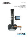
1
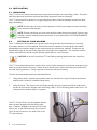
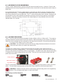
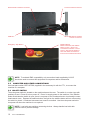
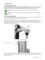
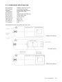
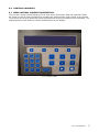
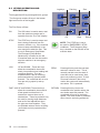
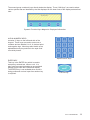
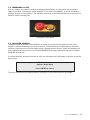
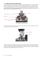
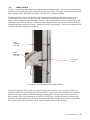
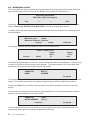
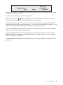
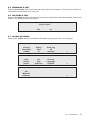
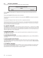
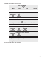
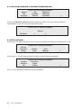
Part No. 01/3935 July 2013 FT1 Series Friction Tester Machines User Manual FT1 User Manual 1 WARRANTY This instrument is warranted against defects in workmanship, material and design for one (1) year from date of delivery to the extent that AMETEK will, at its sole option, repair or replace the instrument or any part thereof which is defective, provided, however, that this warranty shall not apply to instruments subjected to tampering or, abuse, or exposed to highly corrosive conditions. THIS WARRANTY IS IN LIEU OF ALL OTHER WARRANTIES WHETHER EXPRESS OR IMPLIED AND AMETEK HEREBY DISCLAIMS ALL OTHER WARRANTIES, INCLUDING, WITHOUT LIMITATION, ANY WARRANTY OF FITNESS FOR A PARTICULAR PURPOSE OR MERCHANTABILITY. AMETEK SHALL NOT BE LIABLE FOR ANY INCIDENTAL OR CONSEQUENTIAL DAMAGES, INCLUDING, BUT NOT LIMITED TO, ANY ANTICIPATED OR LOST PROFITS. This warranty is voidable if the purchaser fails to follow any and all instructions, warnings or cautions in the instrument’s Instruction Manual. If a manufacturing defect is found, AMETEK will replace or repair the instrument or replace any defective part thereof without charge; however, AMETEK’s obligation hereunder does not include the cost of transportation, which must be borne by the customer. AMETEK assumes no responsibility for damage in transit, and any claims for such damage should be presented to the carrier by the purchaser. TRADEMARKS AMETEK is a registered trademarks of AMETEK, Inc. LLOYD INSTRUMENTS is a trademark of AMETEK, Inc. Other trademarks are the property of their respective owners. SUPPORT AMETEK Lloyd Instruments Ltd Steyning Way Bognor Regis West Sussex UK PO22 9ST Tel: +44 (0) 1243 833 370 Fax: +44 (0) 1243 833 401 [email protected] www.lloyd-instruments.co.uk AMETEK Measurement and Calibration Technologies 8600 Somerset Drive Largo, FL 33773 USA Tel:+1-727-536-7831 Tel: +1-800-527-9999 (within USA only) www.chatillon.com 2 FT1 User Manual CAUTION! HIGH FORCES ARE OFTEN INVOLVED WITH THE MATERIAL TESTING PROCESSES. THE MACHINE IS POWERED BY MAINS SUPPLY VOLTAGE CLASS 1 PRODUCT, MUST BE CONNECTED TO A MAINS SOCKET OUTLET WITH A PROTECTIVE EARTH CONNECTION DO NOT POSITION THE EQUIPMENT SO THAT IT IS DIFFICULT TO OPERATE THE DISCONNECT DEVICE (MACHINE MAINS INLET SOCKET) IF THE EQUIPMENT IS USED IN A MANOR NOT SPECIFIED BY THE MANUFACTURER, THE PROTECTION PROVIDED BY THE EQUIPMENT MAY BE IMPAIRED TO MAINTAIN ALL ASPECTS OF THE SPECIFICATION, ONLY LLOYD INSTRUMENTS APPROVED ACCESSORIES CONNECTIONS AND COMPONENTS SHOULD BE USED STRICTLY ADHERE TO ALL SPECIFIED SAFETY PROCEDURES READ THIS MANUAL BEFORE USING THE MATERIALS TESTING MACHINE. Icons WARNING The raised hand icon warns of a situation or condition that may lead to personal injury or death. Do not proceed until the warning is read and thoroughly understood. Warning messages are shown in bold type. DANGEROUS VOLTAGE The lightning icon warns of the presence of an uninsulated dangerous voltage within the product enclosure that might be of sufficient magnitude to cause serious shocks or death. Never open the enclosures unless you are an authorized and qualified LLOYD INSTRUMENTS’ service personnel. Never open any enclosure when power is connected to the system or its components. CAUTION The exclamation point icon indicates a situation or condition that may lead to equipment malfunction or damage. Do not proceed until the caution message is read and thoroughly understood. Caution messages are shown in bold type. NOTE The note icon indicates additional or supplementary information about the action, activity or concept. Notes are shown in bold type. General Safety General safety precautions must be followed when using this LLOYD INSTRUMENTS product. Failure to observe precautions and warnings may result in damage to the equipment, or injury to personnel. It is understood that safety rules within companies vary. If a conflict exists between the material contained in all LLOYD INSTRUMENTS’ User’s Guides and the rules of a company using a LLOYD INSTRUMENTS product, the more stringent rules should take precedence. Safety Considerations The FT1 is completely enclosed and provides no potentially hazardous outputs. Safety considerations are related to the power connections and physical mountings. Electronic and mechanical components housed within the FT1 covers are to be serviced by authorized LLOYD INSTRUMENTS’ representatives only. safety of the operator, other people, machine and properties by providing guards, shields, screen, adequate lighting, adequate ventilation, ect. Furthermore, when the machine is installed, wired and ready for its intended use the final user must conduct the final Risk Assessment on the machine, including all such safety measures (shield, guard, etc.), to satisfy the requirements of Machinery Directive and EHSR (Essential Health and Safety Requirements). The FT1 Frame has a potential to crush objects! Please ensure your hands are kept away from the FT1 moving arm. When designing custom fixtures! Ensure fixtures load ratings exceed the FT1 load cell maximum load rating. I.e. If load cell is 1kN the fixtures must be designed to exceed 1kN load. The final and full compliance with the requirements of the MSD 2006-42-EC will be dependant on the industry, application, material (to be tested), location (of the use), ect. the final user must take the necessary steps to ensure the FT1 User Manual 3 4 FT1 User Manual TABLE OF CONTENTS 1.0 INTRODUCTION................................ 6 1.1Safety.................................................. 7 2.0 Electrical Safety...................... 7 3.0 INSTALLATION.................................. 8 3.1Unpacking........................................... 8 3.2 Setting Up Your Machine.................... 8 3.3 Securing to the workbench................. 9 3.4 Voltage Selection................................ 9 3.5 Computer and Other Connections..... 10 3.6 ON-OFF Switch.................................. 10 3.7 Fitting the Load Cell........................... 11 3.8 Additional Load Cells......................... 11 3.9 Fitting the Friction Tester bed............. 12 3.10 Fitting the String Holder..................... 12 4.0 4.1 4.2 4.3 LOAD CELLS.................................... Care of Load Cells............................. Fitting Load Cells............................... General Precautions.......................... 13 13 13 14 5.0 ACCESSORIES and STRUCTURE.. 15 CONTROL CONSOLES.................... Main Control Console Description..... Keypad Operation and Description.... The Display........................................ “SWITCH-ON” DIisplay...................... 17 17 18 20 20 7.0 OPERATIONAL PRECAUTION........ 7.1Safety................................................. 7.2 Emergency Stop................................ 7.3 Splinter Shields.................................. 7.4 Lower Anchor Pin Adjustment............ 7.5 Limit Stops......................................... 22 22 23 23 24 25 PERFORMING A TEST..................... Performing a Test............................... Test Parameters................................. Selecting a Test.................................. Starting a Test.................................... Stopping a Test.................................. Printing Test Results.......................... Canceling or Accepting Results......... Viewing the Statistics......................... Error Conditions................................. 27 27 27 28 30 30 30 30 31 31 6.0 6.1 6.2 6.3 6.4 8.0 8.1 8.2 8.3 8.4 8.5 8.6 8.7 8.8 8.9 9.0 SETTING UP A NEW TEST............... 9.1 Pre-defined Test Setups..................... 9.2 Default Global Settings...................... 9.3 Editing a Pre-defined Test Setup....... 9.4 Password Access............................... 9.5 Renaming the Test............................. 9.6 Deleting a Test................................... 9.7 Global Settings................................... 9.8 Setting a Password............................ 9.9 Safety Load Limit............................... 9.10 Slow Jog Speed................................. 9.11 Setting for Printer............................... 9.12 Grip Protection Settings..................... 9.13 Current Language.............................. 9.14 Machine Stiffness............................... 9.15 Test Setup Display............................. 9.16 Test Type............................................ 9.17 Selecting Machine Stiffness Compensation.................................... 9.18 Test Options....................................... 9.19 Test Results....................................... 9.20 Pass/Fail Values................................ 9.21 Defining Sample................................. 9.22 Pre-Test Questions............................ 32 32 34 34 34 35 35 35 36 36 36 36 36 36 37 37 38 40 40 43 43 44 44 10.0 ERROR CONDITION......................... 45 10.1 Error Conditions................................. 45 11.0 CLEANING AND MAINTENANCE.... 47 11.1 Cleaning External Finish and Trim..... 47 11.2Maintenance...................................... 47 12.0 TECHNICAL SPECIFICATION.......... 48 12.1 Technical Specification - FT1............ 48 12.2 Overall Dimensions FT1.................... 49 13.0 RoHS tables....................................... 50 14.0 Spare Parts Kits................................. 51 FT1 User Manual 5 1.0INTRODUCTION Welcome to your new FT1 series advanced, single column, universal testing machine. It incorporates an extensive range of features making it ideal for performing complex testing applications. The machine is microprocessor controlled and uses world proven 32 bit technology for highly accurate load measurement and rapid data acquisition. NEXYGENPlus™ data analysis and applications software, please contact your authorised LLOYD INSTRUMENTS Sales Representative. The stand alone system is capable of storing up to 600 test results from a choice of 10 user programmable test set-ups, or may be connected via its USB output to a personal computer running NEXYGENPlus™, providing almost unlimited testing capability and result manipulation facilities. The high stiffness frame incorporates a crosshead guidance system to prevent side loading of the sample under test. The crosshead is driven by single lead screw, motor and DC PWM system to achieve a wide speed range over the full load range. The machine is capable of running full load at full speed. A range of highly accurate, interchangeable loadcells are available for tension, compression and cycling through force measurements. The system is ideal for use in production, quality control, educational and research environments. The FT1 is designed to meet a broad range of applications. This is achieved mainly through the embedded control software and easily configurable data acquisition software, available as an optional extra. NEXYGENPlus™ software is fully WINDOWS® compliant and compatible, it seamlessly integrates with contemporary MICROSOFT® Office programs using OLE2 technology. The program is easy to use, making use of drop down windows prompts, drag and drop, cut and paste routines. Data can easily be exported to programs such as EXCEL®, ACCESS®, OUTLOOK® and POWERPOINT® for further manipulation, and enhanced presentation. NEXYGENPlus™ software contains a library of pre-programmed test set-ups for conducting fully automated tests, in accordance with international standards. For advice and information about the 6 FT1 User Manual FT1 with friction table 1.1SAFETY CAUTION: Materials testing machines are very safe to use providing the instructions presented in this manual are followed precisely. We would like to draw your attention to both the Electrical Safety (Section 2.0 page 7) and Operational Precautions, (Section 7.0 page 23). Please refer to both sections for details on safe operation of this equipment before operating your materials testing machine. Transparent splinter shields are available as an option to enclose the test sample if there is any danger of samples shattering as a result of the test. These shields have an electronic interlock such that the test cannot be started until the hinged shield is closed. While not mandatory for many applications and countries, AMETEK Lloyd Instruments Ltd. strongly recommends that users consider fitting this option. 2.0 ELECTRICAL SAFETY 1.The FT1 Friction Tester has been designed to meet the requirements of BS EN 61010-1 : 2001 Safety requirements for electrical equipment for measurement, control and laboratory use. 2. The User Manual contains some information and warnings, which have to be followed by the user to ensure safe operation and to keep the machine in safe condition. 3. The machine has been designed for indoor use. It may occasionally be subjected to temperatures between -10ºC and +35ºC (14ºF and 95ºF) without degradation of its safety. 4. Before switching on the machine make sure that it is set to the voltage of the mains electricity supply. 5. This machine complies with electrical safety grade Class 1, which means that it is “earthed apparatus” and requires the mains plug to contain a protective earth terminal. The mains plug must only be inserted in a socket outlet provided with a protective earth contact. The protective action must not be negated by the use of an extension cord without a protective conductor. 6. Make sure that only fuses with the required rated current and of the specified type are used for replacement. The use of makeshift fuses and the short-circuiting of fuse holders is prohibited. 7. There are no user serviceable parts within the machine. 8. The machine must be disconnected from all voltage sources before it is opened for any adjustments, replacement, maintenance or repair. 9. Capacitors inside the machine may still be charged even if the machine has been disconnected from all voltage sources. 10. Any adjustment, maintenance or repair of the opened machine connect to the mains supply voltage should be avoided as far as possible but if inevitable, must only be carried out by a skilled person who is aware of the hazard involved. 11. Only use safety approved power cords that come with the FT1 Series test machines. FT1 User Manual 7 3.0INSTALLATION 3.1UNPACKING The FT1 on its own, without the packing and accessories weighs more than 50kg (110lb). Therefore, safe lifting practices should be employed and lifting equipment used as necessary. The FT1 test machine is packed in a rugged shipping crate to minimize damage caused from shipping mishandling. NOTE: Please make a careful visual inspection of all the parts made to ensure that there is no obvious transit damage. NOTE: Please check that you have received all the parts that were ordered. If there is any damage, or parts missing, please report them to your authorised LLOYD INSTRUMENTS representative. 3.2 SETTING UP YOUR MACHINE The FT1 Materials Testing Machine is a heavy item and great care should be taken in choosing the location where it is to be installed. Ensure the bench is capable of remaining firm and stable, withstanding the combined weight of the machine and any accessories supplied. Please see the Specification page at the end of this manual for the weight of the apparatus. The machine must be vertical, otherwise the results may be affected, particularly for very low loads. CAUTION: At no time should the FT1 be lifted by placing hands under the frame feet. The FT1 must be positioned such that the front can be easily accessed, and that the emergency stop button is not obstructed in any way. Please ensure utmost care is taken when lifting this instrument, use safe working practices. Lifting equipment should be used as necessary. The two recommended methods are described below: 1. 2. Lifting with a pallet. A pallet may be fitted under the machine so it may be lifted to the desired position with a forklift or a suitable lifting trolley. Lifting by hand. The machine can be lifted manually, at least 2 people should be employed to do this as the machine weighs more than 50kg (110lb). Do not lift using plastic base cover. Lift using aluminum bottom plate as a support. The FT1 Friction Tester may be shipped with the load cell cable plugged into itself during shipping. If cable is plugged in as shown to the right remove the 15 pin connector and plug it into the 15 pin D-sub connector in the lower rear of the FT1 test machine. 8 FT1 User Manual 3.3 SECURING TO THE WORKBENCH The FT1 series material tester is a heavy item and cannot normally tip over. However, if there is the possibility that users can pull against the vertical column, then there is a risk that the machine may be pulled over. It is required that the FT1 series material tester is secured to the bench using the 2 tapped holes in the base of the machine. The template below shows the location of 2 holes that are required in the top of the workbench for the two M6 bolts. The FT1 series test machine has 2 screws, 2 spacers and two washers as part of the standard accessories to properly mount the test machine to a standard workbench. If the two mounting screws are the wrong length you may substitute the screws with standard M6 X P1.0 screws. 3.4 VOLTAGE SELECTION The FT1 can be used with electricity supplies of either 230Vac ±10% or 115Vac ±10%. The power input cable should be inserted at the rear of the machine. Before switching on the machine you MUST check the correct voltage has been selected on the mains input connector. Ensure that the selection is correct for the voltage of your power supply. CAUTION: You must check to ensure the correct voltage has been selected on the mains input connector before you switch the machine ON. To change the voltage setting, unplug the mains lead from the back of the machine and use a screwdriver to open the voltage selector. The screwdriver should then be used to move the selector from the 115V position to the 230V position as appropriate. You MUST also check that the fuse rating is suitable for the supply voltage that you are using. The fuses (live and neutral) located inside the power input connector. Voltage Selection Main Power Switch Power Mains Input The FT1 test machine uses two ceramic high breaking capacity type fuses (20mm x 5mm) as shown above. The two fuses are assembled into the power entry module fuse block as shown above. WARNING: Replace the fuses with the exact same type and rating as the ones supplied by factory. Do not replace with higher or lower rated fuses. Fuse Ratings and Part Numbers Model Fuse Rating FS1 - 115VAC 3.15A FS1 - 230VAC 3.15A Part Number SPK/LS1/0011/A SPK/LS1/0011/A Type T3A15H250V T3A15H250V FT1 User Manual 9 Extensometer Interface Connector Load Cell Cable Connector USB Port Hand Held Remote or Main Console Connector Emergency Stop Button Safeline Button When illuminated, the safeline switch is open. There is no crosshead movement or motor control. Depress the button to close the switch and allow for motor and crosshead movement. NOTE: To maintain EMC compatibility, only connection leads supplied by LLOYD should be used to connect this equipment to computers and/or accessories. 3.5 COMPUTER AND OTHER CONNECTIONS Use lead part number CBT/1357/00, supplied in the accessory kit with the FT1, to connect the machine to a computer. 3.6 ON-OFF SWITCH The main power switch is located on the machine base at the rear. The switch is a rocker type with positions O and l. Press O to turn power off. Press I to supply power to the machine. If the safeline button illuminates the switch is open- there is no power to the crosshead motor circuit and the crosshead cannot move. Depress the safeline button, the light on the safeline button will turn off meaning the switch is closed. Crosshead movement can now be controlled. Use the main power switch to turn power off when the machine is not required. NOTE: Load cells are precision measuring devices. Always handle load cells with extreme care to prevent damage. 10 FT1 User Manual 3.7 FITTING THE LOAD CELL Before the machine is powered up, or any test set-ups are entered, the Load Cell should be fitted. Carefully unpack the Load Cell(s) supplied with your machine. Please make all operators aware that they are precision load measuring devices and should be treated with great care. Please read SECTION 4.0 LOAD CELLS before proceeding further. 3.8 ADDITIONAL LOAD CELLS The following standard Load Cells are available for your FT1. DescriptionAccuracy CapacityOrder Number YLC-0005-A1 0.5% accuracy 5N 01/3871 YLC-0010-A1 0.5% accuracy 10N 01/3872 YLC-0020-A1 0.5% accuracy 20N 01/3873 YLC-0050-A1 0.5% accuracy 50N 01/3874 YLC-0100-A1 0.5% accuracy 100N 01/3875 YLC-0250-A1 0.5% accuracy 250N 01/3876 YLC-0500-A1 0.5% accuracy 500N 01/3877 YLC-1000-A1 0.5% accuracy 1000N 01/3878 YLC-2500-A1 0.5% accuracy 2500N 01/3879 YLC-5000-A1 0.5% accuracy 5000N 01/3880 FT1 Load Cell resolution Load Cell LBF Resolution 5N 1LBF X 0.00001 LBF 10N 2 LBF X 0.0001 LBF 20N 5 LBF X 0.0001 LBF 50N 10 LBF X 0.0001 LBF 100N 20 LBF X 0.001 LBF 250N 50 LBF X 0.001 LBF 500N 100 LBF X 0.001 LBF 1000N 200 LBF X 0.01 LBF 2500N 500 LBF X 0.01 LBF 5000N 1000 LBF X 0.01 LBF N Resolution KGF Resolution 5 N X 0.0001 N 0.5 KGF X 0.00001 KGF 10 N X 0.0001 N 1 KGF X 0.00001 KGF 20 N X 0.001 N 2 KGF X 0.0001 KGF 50 N X 0.001 N 5 KGF X 0.0001 KGF 100 N X 0.001 N 10 KGF X 0.0001 KGF 250 N X 0.01 N 25 KGF X 0.001 KGF 500 N X 0.01 N 50 KGF X 0.001 KGF 1000 N X 0.01 N 100 KGF X 0.001 KGF 2500 N X 0.1 N 250 KGF X 0.01 KGF 5000 N X 0.1 N 500 KGF X 0.01 KGF GF Resolution 500 GF X 0.01 GF 1000 GF X 0.01 GF 2000 GF X 0.1 GF 5000 GF X 0.1 GF 10000 GF X 0.1 GF 25000 GF X 1 GF 50000 GF X 1 GF 100000 GF X 1 GF 250000 GF X 1 GF 500000 GF X 1 GF FT1 User Manual 11 3.9 FITTING THE FRICTION TESTER BED After the machine has been levelled the friction testing plate should be fitted. Remove the two support legs from the packaging and screw the feet (FTT/0140/00) fully into the support legs to make the support legs as short as possible. Fit the two support legs by screwing them in to the two threaded holes. (see drawing below) To fit the table to the FT1, use the two supplied M6 button head screws, the table has two holes either side of the pulley wheel, these will align with the two M6 holes on the bottom mounting boss. The screws should be tightened until there is no movement horizontally or vertically by the table. BOTTOM MOUNTING BOSS Bottom mounting boss of FT1 showing the 2 M 6 tapped holes for securing the table to the base Look at the bubble in the spirit level and check that the whole machine is level. If necessary use the feet on the FT1 to re-adjust the level of the instrument until the spirit level on the table has the bubble positioned in the centre and the table is level. Next, slowly unscrew the support feet and increase the support column length until the end of the table is supported but be careful not to over extend the legs to raise the table end and offset the level. 3.10 FITTING THE STRING HOLDER Fit the String Holder as shown above and tighten the 2 locking nuts to secure it in place 12 FT1 User Manual 4.0 LOAD CELLS 4.1 CARE OF LOAD CELLS ALL machine operators should be aware that LLOYD INSTRUMENTS’ Load Cells are precision force measuring instruments, which should be treated with the utmost care to avoid accidental damage. In particular low force Load Cells are easily damaged if abused or used without sufficient care. NOTE: Do not submit Load Cells to physical shock of any kind. DO NOT DROP! NOTE: When a Load Cell is removed from a machine immediately put it in a safe and dry place. 4.2 FITTING LOAD CELLS Place the Load Cell fixing screw through the hole in the crosshead and carefully offer up the load cell with the connecting lead facing inwards under the crosshead. Screw the fixing screw (A) into the load cell (D), taking care to ensure that the locating dowel (B), when fitted) on the load cell sits in the hole in the moving crosshead. Tighten the screw with the 8mm HEX key provided. Insert the load cell plug (C) in the socket on the top of the moving crosshead and finger tighten the two retaining screws. C B A D FT1 Load Cell Fitting Load Cell Cable Support The Load Cell Cable Support can be adjusted up or down on the FT1 Column Extrusion using a 5mm Hex Key. Ensure there is plenty of length in the cable so that the crosshead can travel without pulling the cable assembly. FT1 User Manual 13 4.3 GENERAL PRECAUTIONS The following points should be considered: 1. When installing the upper grip (particularly heavy ones) on the load cell eye end, avoid bumping the eye end. If the grip is a close fit, DO NOT FORCE IT, establish the reason and rectify. Immediately set, or re-set, the bottom limit stop so the grips will not meet when the crosshead is lowered. See section 7.5 LIMIT STOPS. 2. In both tension and compression tests, centre the specimen in line with the axis of the load cell and the bottom fixed anchoring device or pin to avoid side thrust. 3. In compression tests, care must be taken to avoid bringing the platens together or against solid specimens at high speed. Load cells thus damaged cannot be repaired. Ensure that the lower crosshead limit is set correctly. See section 7.5 LIMIT STOPS. 4. In compression tests, if special lower fixtures are used, ensure that they are fixed in position so they cannot be accidentally moved to block the normal downward movement of the upper fixture, e.g. where a tongue on the upper fixture must fit into a slot in the lower fixture. See section 7.4 LOWER ANCHOR PIN ADJUSTMENT. 5. Avoid overloading beyond the load cell rated capacity. Prior to testing ensure, if possible, that the maximum force anticipated will not exceed the capacity of the cell installed. If maximum capacity is approached during a test, run the machine at slow speed in local mode, and reverse the crosshead if capacity is exceeded. 6. LLOYD INSTRUMENTS load cells are built to exceed the standards as set out by ASTM, BS, DIN etc. All load cells on FT1 machines are user-changeable. Various capacities are available from 5N up to the capacity of the frame. While cells may be used below 10% of capacity it is recommended that, when such lower forces are anticipated, a lower force cell be installed such that the test force will fall in the upper 90% of its range. This will give the best signal to noise performance of the load measuring system. NOTE: All machines incorporate overload protection, which will stop the machine if capacity is exceeded in either tension or compression. However, at higher speeds, momentum may carry the crosshead far enough after shut-off to damage the cell. All load cells can be damaged this way but in low force cells this distance is very short. Load cells that incur damage due to overloading cannot be repaired. 14 FT1 User Manual 5.0 ACCESSORIES AND STRUCTURE BOT/0184/00 Adaptor Load Cell To Cord SCT/0318/00 Cord Retaining Screw 07/1183 Pulley Wheel With Bearing TPE/0132/00 Double Sided Tape PLT/1270/00Sled BRT/0833/00 Sample Attachment Bracket PLT/1272/00 Friction Base Table SRT/0220/00 Tension Spring DRW/0012/00 Drive Cord LST/0141/00 Spirit Level PIT/0255/00 Support Leg FTT/0140/00Foot See sketches below to see where parts are used. ASTM D1894 Set-up ISO 8295 Set-up TAPPI D1894 Set-up FT1 User Manual 15 ASTM D 1894 Sled Size 63.25mm ±0.25mm square Sled Weight 200g ± 5g Lower sample size 130 x 250 mm Upper sample size 120 x 120 mm Test speed 150mm/min ± 30mm/min Test movement 130mm Sled movement Cord to sled Plate and spring required No ISO 8295 Sled Size 63.25mm±0.25mm square Sled Weight 200g ± 2g Lower sample size 80 x 200 mm Upper sample size 80 x 200 mm Test speed 100mm/min +/- 10 mm/min. 500mm/min may be used but must be reported Test movement 60 – 100 mm Sled movement Cord to film via plate and spring Plate and spring required Yes TAPPI T549 Sled Size 63.25mm±0.25mm square Sled Weight 200g ± 5g Lower sample size 100 x 215 mm Upper sample size 75 x 130 mm Test speed 150mm/min ± 30 mm/min Test movement 130 mm Sled movement Cord to sled Plate and spring required No 16 FT1 User Manual 6.0 CONTROL CONSOLES 6.1 MAIN CONTROL CONSOLE DESCRIPTION The unit has a Liquid Crystal Display (LCD) to show set-up information, load and extension values etc. and a key pad to input information for operating the machine when under control of the console. The machine is set up by answering simple questions and entering information when requested. The operating status of the machine is shown and described on the display. FT1 Control Panel FT1 User Manual 17 6.2 KEYPAD OPERATION AND DESCRIPTION Jog Keys Fast Jog Zero The keypad has 25 keys arranged into 4 groups. The first group contains 8 keys in the bottom right hand corner of the keypad The First Group of Keys GO The GO button is used to start a test from the machine console and is operable from the “Pre-Test” display. Go STOP The STOP key is used to stop a test that is being performed from the machine console, e.g., if the machine does not stop automatically or the user requires to abort the test. This is not an Emergency Stop Button. The Emergency Stop Button (Mushroom) is located on the left of machine base and can be used to stop the machine in an emergency situation. JOG UP and DOWN These two keys allow the crosshead to be moved slowly into position when loading and removing samples. They are available when a test is not being performed and only operate whilst pressed. The crosshead will run at a user pre-set jog speed (a set-up option). FAST JOG UP and DOWN These two keys allow the crosshead to be moved at a fast speed and therefore it is essential to ensure there are no obstructions. These keys should only be used for moving large distances and not for final adjustment when the grips are close together. They are available when a test is not being performed and only operate whilst pressed. 18 FT1 User Manual Stop Return NOTE: The STOP key is not to be used for EMERGENCY STOP conditions. The Emergency Stop key is located on the left-side of the machine base. ZERO Pressing this key sets the load and extension values to zero. This is normally carried out at the start of a test but can be used at any time when not performing a test. If Auto Zero was selected in the set-up routine the system will automatically zero when GO is pressed. RETURN Pressing this key returns the crosshead to the position where the zero button was last pressed. The crosshead will move at maximum speed. The return button is available when a test is not being performed. The second group contains 4 keys directly below the display. These “Soft Keys” are used to select various options that are identified by the text displayed on the lower lines of the display as described later. Dynamic Function Keys Mapped to Displayed Information ALPHA-NUMERIC KEYS contains 12 keys on the left hand side of the keypad. These keys are used to enter text or numbers and are labelled 1 to 9, 0, decimal point and negative sign. Most keys also double up as alphabetical entry keys similar to the style used on mobile phones. ENTER KEY This key is the ENTER key which is used to accept any entered text, value or unit. It is also used to accept the entries on a completed display and to show the PREVIOUS display. The ENTER key is not available when a test is being performed or when input from another key is required. Alpha-numeric Keys ENTER Key FT1 User Manual 19 6.3 THE DISPLAY The display, which has 4 lines of 40 characters, is used to show or request information. The information displayed depends upon the status of the machine but generally, the top line displays a title or help information for each display. The lower lines are split into 4 blocks, one block above each Soft Key, to indicate the function of that key. 6.4 “SWITCH-ON” DISPLAY When first switched on the display will be blank while the system performs some routine checks. After a few seconds the display will show information about the machine and the version of the embedded software installed. Similar to the one shown below.. LLOYD INSTRUMENTS LTD Friction Tester S/No 123456 Version 3.5 Issue 1 Load Cell 1 kN This information is displayed for three seconds after which the test selection screen is displayed. The next display shows that a test called CYCLE_TEST has been defined. The number in brackets shows the number of sample results currently stored with this test. Select the required test ASTM D 1894 (0 Samples) Test< > Edit Select the required test ISO 8295 (0 Samples) Test< > Edit Select the required test TAPPI T549 (0 Samples) Test< > Edit Select one of the test defined above. The number in brackets shows the number of sample results currently stored with this test. A total of 600 sample results can be stored across all test set-ups. If the total number of samples currently stored with all the test set-ups exceeds 500 then the third line will display a warning message. Select the required test FRICTION_TEST (501 samples) Warning: Only space for 99 more samples Test< > Edit As the left and right arrow ( < > ) Soft Keys are pressed, the names of the previously defined tests will be shown. 20 FT1 User Manual When the first test is displayed, the left arrow will be hidden as shown below. Select the required test FRICTION_TEST (150 samples) Test< > Edit When the last test is displayed, and less than 10 set-ups have been defined the display below will be shown. Select the required test New Test < Create To define a test, refer to Section 9.0 SETTING UP A NEW TEST, noting that the supervisor may add a password to prevent the operator from entering the EDIT or CREATE modes. FT1 User Manual 21 7.0 OPERATIONAL PRECAUTIONS 7.1SAFETY LLOYD INSTRUMENTS testing machines are inherently safe if used properly. Operators must be made aware that:1 2 3 4 5 6 7 8 9 High physical forces are involved. Samples under test may shatter. Electrical power supplies are involved. The following must ALWAYS be brought to the attention of any operator before they are allowed to use the machine. Hands, fingers and other parts of the body must at all times be kept well away from the moving crosshead. Operators should be particularly careful when moving the crosshead to insert test samples, to ensure that no part of the hand could be accidentally compressed as the crosshead and grips are jogged into position. NEVER drive the machine from a computer when anyone else is working on or near the machine. If there is any danger that liquids may be spilt during tests, operators must use a drip tray (which is available from LLOYD INSTRUMENTS) to guard against the possibility of any spillage entering the machine and giving rise to electrical or other hazards. Take extra care when operating in compression mode where specimens may burst, shatter or fly out from between the platens. Operators should STAND CLEAR during testing. Splinter shields are available in various options to suit specific requirements. All operators must receive adequate training in basic operation before being allowed to use the machine. Additional copies of this manual are available from AMETEK Inc. Operators must ensure that the Emergency Stop Button is never obstructed. 10 Operators must ensure that other personnel working in or near the area are made aware that testing is taking place and that they should not approach the machine while it is in use. 11 Operators must ensure that the machine is regularly serviced and calibrated by LLOYD INSTRUMENTS, or one of their accredited service dealers. 12 To maintain EMC compatibility, the machine should only be used as prescribed in this manual. Connecting cables, plugs and sockets should be inspected regularly. Cables damaged or worn in any way should not be used. Accessories and accessory connecting leads, if suspect, should be replaced only with a LLOYD INSTRUMENTS approved replacement. Failure to observe this may cause your machine to infringe the EMC legal requirements. 13 NEVER attempt any form of machine maintenance without disconnecting the mains electrical supply. 14 NEVER attempt to test any samples with a type of grip or other accessory, which is not designed for that particular test. Never use grips or the machine for tests in excess of the stated load limits. A comprehensive range of alternative grips, together with an applications advisory service, is available from LLOYD INSTRUMENTS and their accredited dealers. 22 FT1 User Manual 7.2 EMERGENCY STOP If for any reason, the machine needs to be stopped without delay, an emergency stop mushroom switch is provided. Pressing the switch stops the FT1 machine immediately. It can be released by turning a quarter-a-turn clockwise. The machine will then go to the initialized/start-up sequence if the ON/OFF switch is already ON. Emergency Stop Switch 7.3 SPLINTER SHIELDS Transparent splinter shields are available as an option to enclose the test sample if there is any danger of samples shattering as a result of the test. These shields can be fitted with an electronic interlock so that the test cannot be started until the hinged shield is closed. While not mandatory for many applications and countries, LLOYD INSTRUMENTS strongly recommend that users consider fitting this optional item. If a shield fitted with electronic interlock is used, the following screen will appear if the door is opened during a test. ERROR condition Splinter Shield Open Press ENTER to cancel The test in progress will be aborted and the next test or a new test will have to be started. FT1 User Manual 23 7.4 LOWER ANCHOR PIN ADJUSTMENT The Lower Anchor Pin can be adjusted to align itself with the attached load cell. To align the load cell to the lower anchor pin lower the load cell on to the moving ram so that it is very close to the lower anchor pin using the jog keys. Loosen the anchor nut using the spanner wrench provided. Loosen the 4 set screws using a 2.5mm hex key. Align the lower anchor pin to the load cell anchor pin and then re-tighten the 4 set screws so that the two anchor pins are properly aligned with each other. Retighten the anchor nut using the spanner wrench. Collar Lower anchor pin Anchor nut Set screws Lower Anchor Pin Locking Collars The collar is used to secure the lower grip in place. Use the spanner wrench provided to secure the lower grip to the collar as shown below. Lower grip Collar Extreme care must be taken when manoeuvring the crosshead, particularly when low force load cells are being used as they can easily be damaged even at moderate speeds. As an additional precaution during compression testing the lower (hardware) limit stop should be set so that the compression plates cannot come together either during or after a test. 24 FT1 User Manual 7.5 LIMIT STOPS The FT1 machines are fitted with two mechanically activated limit stops. These can be used as extra protection to stop load cells, grips or fixtures coming into contact. The upper one can be used to back up the software limit. Activating a limit stop will result in the machine stopping. To adjust the lower limit stop, first loosen the lower limit stop screw and move the stop to the bottom of its travel in the slot. Drive the moving crosshead to the lowest position that it may go to safely, without damaging any fitted grips or fixtures. When this position has been reached, drive the crosshead up by 3mm (0.125 inch). Move the lower adjustable limit stop up until it stops against the crosshead actuator within the column. Tighten the screw in this position. Ensure the screws are free to move vertically to actuate the switches. Upper Adjustable Limit Stop Lower Adjustable Limit Stop Crosshead actuator FT1 Machine Showing Mechanical Limit Switches To adjust the top limit stop, loosen the upper limit stop screw and move the screw to the top of its travel and tighten the screw temporarily in this position. Drive the moving crosshead to the highest position it may go to safely, without damaging any fitted grips or fixtures. When this position has been reached, drive the crosshead down by 3mm (0.125 inch). Loosen the upper limit stop screw and move the screw down to the limit stop cross head actuator and tighten the screw in this position. Once again, ensure the screws are free to move vertically to actuate the switches. FT1 User Manual 25 If during a test or when manoeuvring the crosshead, a limit stop switch is activated, a display as shown below or similar will be seen. ERROR condition Lower limit switch press ENTER to cancel When ENTER has been pressed and this display has been cleared the machine will only allow the operator to drive the crosshead away from the limit stop. 26 FT1 User Manual 8.0 PERFORMING A TEST 8.1 PERFORMING A TEST The FT1 machines can be used to perform tests in two modes, as a stand-alone machine or under computer control with NEXYGENPlus™ software. If the machine is to be used with a computer and NEXYGENPlus™ software, then the NEXYGENPlus™ Software User Manual supplied with the software, should be read in conjunction with this manual. The machine should be connected to the computer with the USB lead supplied. When the machine is on and ready, the computer connected with the lead supplied, and NEXYGENPlus™ running, connection between the machine and computer is automatic. If the FT1 machine is being used in “stand alone” mode, proceed as follows. The following information will also be needed for “setting up” the machine with grips, samples etc. 8.2 TEST PARAMETERS SAMPLE PREPARATION The Jog Keys are used to prepare for a test. The accessories being used will be dependent on the type of test being conducted. LOAD CELLS The correct load cell should be fitted in the machine for the application being undertaken. Great care should be taken with these as they are precision measurement devices and can be damaged if used incorrectly. Please make sure that you have read Section 4.3 carefully before proceeding further. GRIPS/ADAPTORS It is important that grips are fitted along the central straining axis of the machine and that no side loads are applied to the load cell as this will affect the accuracy of the load readings. The grips should be connected to the load cell and the bottom anchor pin or fixture using only the pins and parts provided. Care should be taken not to exceed the load rating of the grips. It is important to ensure that the grips used are suitable for the material under test. Any slippage of the material in the grips will affect both load and extension readings. EXTENSOMETERS It is important to understand that the extension that the crosshead moves does not give a true reading of the strain in the samples. If we consider a dumbbell sample for instance, the strain will be different at different positions along the sample and no account is being taken of the take up of slack or bedding in of the grips. For accurate strain readings we would strongly recommend the use of a LLOYD INSTRUMENTS extensometer, which is suited for the material under test. FT1 User Manual 27 8.3 SELECTING A TEST The user selects the required existing pre-programmed test by pressing the left and right arrow Soft Keys until the required test is shown on the display, then pressing the Test Soft Key. Select the required test FRICTION_TEST (150 samples) Test< > Edit Depending on how the test has been set up one or more of the following screens will be displayed. Refer to Section 9.0 SETTING UP A NEW TEST for details on setting these options. If a plotter output has been selected and a plotter interface box connected then the following screen will be displayed. Check Plotter Calibration Maximum Load 100.0N Maximum Extension100.0mm AcceptAbort Calibrate Pressing the Calibrate Soft Key allows the user to the following screen Output a Plotter Limit Output 100.0 Accept Abort N Output 100.0 mm If the batch questions option is turned on, then the following screen will be displayed. A “batch” being a series of tests all carried out with the same settings. The “batch questions” are 3 two word questions which can be set-up at the beginning of a new “batch” Press a key to change a parameter OPERATOR BATCH NAMENUMBER Suspend The information can only be entered when a new batch is started i.e. when sample number 1 is to be tested. The operator can answer the questions by pressing the Soft Key below each question. Pressing the Enter key will confirm all the answers to the batch questions and show the pre-test display. If the operator is continuing with a previously suspended batch, then the batch questions, and their answers, will be displayed in a “view only” mode. OPERATOR DAVE BATCH NUMBER B21_G Continue Suspend Here the operator will be given the option to Continue with the previously suspended batch or to Suspend the batch again by pressing the appropriate Soft Keys. 28 FT1 User Manual Press GO to test Sample 1 BATCH_32 Ext 10.00mm Load 276N StatsReset Suspend On the top line of the Pre-test display help information is shown. On the second line, the right hand side shows the test setup name. On the third line, Extension and Load are displayed. The extension symbols or indicate the direction of the extension from the “soft zero” position. “Soft zero” being the position at which the ZERO key was last pressed. If the sample questions option is turned on, then next to the test name the sample width and thickness, diameter or area information will be shown. The Sample Soft Key will also be displayed. Refer to Section 9.0 SETTING UP A NEW TEST for details on setting these options. Pressing the Suspend Soft Key returns to the test selection display but saves the statistics and last sample number ready to continue the batch later. Pressing the Reset Soft Key resets all the batch results, sets sample number to 1 and shows the display that would be selected when first selecting the test, i.e. batch or pre-test. This is only done after confirmation by the operator. Pressing the Stats Soft Key will show the statistics for the samples tested so far and allow them to be printed. FT1 User Manual 29 8.4 STARTING A TEST When all the test parameters have been set as per 8.3 SELECTING A TEST above, press GO to start the test and display the screen below. Performing Test ASTM1894 Moving to limit point Ext 8888.88mm Load 8888.88N StatsAccept Cancel The FT1 is supplied with three pre-defined test setups and one for new test setups, these are:ASTM D1894 - TAPPI T549 - ISO 8295 These are described in section 9.1 PRE-DEFINED TEST SETUPS. 8.5 STOPPING A TEST When the test ends, either automatically or if the user presses the STOP key, the post test screen will be displayed Sample 1 Passed COF S COF K PK Load 0.002 0.004 12gF Print StatsAccept Ave Load 7gF Cancel This screen will display different amounts of information depending on how the test has been set up. Refer to Section 9.0 SETTING UP A NEW TEST for details on setting these options. 8.6 PRINTING TEST RESULTS Pressing the Print Soft Key will either print just the single result or, if All was selected for the Sample Printout option in the test setup, together with the machine setup details, i.e. test speed etc. 8.7 CANCELLING OR ACCEPTING THE RESULTS Pressing the Cancel Soft Key will cancel the result (abort) and remove the result from the batch. Pressing the Accept Soft Key or the ENTER key will accept the results and add them to the batch. 30 FT1 User Manual 8.8 VIEWING THE STATISTICS Pressing the Stats Soft Key will accept the result and show the statistics screen as below:COF S COF K 0.0123 0.321 0.002 0.003 Print COF/LOAD COF Pressing > Soft Key will show the second statistics screen:Pk Load Ave Load Mean0.1 gF 0.3 gF Dev’n0.002 0.003COF/LOAD Print LOAD Pressing the Print Soft Key from the statistics screen will show the ‘print options’ screen shown below: Print options for ASTM D1894 StatsBrief Full Only ReportReport Pressing the Stats Only Soft Key will give a table of statistics only, without the test value. Pressing the Brief Report Soft Key will give a table of test values and statistics. Pressing the Full Report Soft Key will give a table of test values, statistics and test setup information. 8.9 ERROR CONDITIONS If an error condition exists the cause of the error will be shown on the display. This error must be cleared before you can proceed with the test. See Section 10.1 for details of error messages FT1 User Manual 31 9.0 SETTING UP A NEW TEST 9.1 PRE-DEFINED TEST SETUPS The FT1 is supplied with three pre-defined test setups and one for new test setups, these are: ASTM D1894 ISO8295 TAPPI T549 NEW_TEST Is a user defined test rather than one of the default settings which are detailed on the next page. 32 FT1 User Manual The Default test setups are as follows: Test name > ASTM D1894 ISO 8295 Test Type TAPPI T549 NEW_TEST Settings Test mode Tension Tension Tension Tension L1 10.0 mm 10.0 mm 10.0 mm 10.0 mm L2 130.0mm 60.0mm 120.0 mm 120.0 mm L2 ABS / REL ABS ABS ABS ABS Final Limit 140.0 mm 100 mm 130 mm 130 mm Sled Weight 200 ±2 gm 200 ±2 gm 200 ±2 gm 200 ±2 gm Sled Dimension Area Area Area Area Sled Area 4000 mm2 4000 mm2 4000 mm2 4000 mm2 Test speed 150 mm/min 100mm/min 150mm/min 150mm/min Preload 0.0gf 0.0N 0.0N 0.0N Preload speed 10.0 mm/min 10.0 mm/min 10.0 mm/min 10.0 mm/min Machine Stiffness Disabled Disabled Disabled Disabled Sharp Break detector Off Off Off Off % Break Detector Off Off Off Off Return to zero Manual Manual Manual Manual Zero readings Manual Manual Manual Manual Sample printout All All All All Extenso’r Used Internal Internal Internal Internal Friction Load gf N gf gf Pass/fail Checks Off Off Off Off Batch Questions Off Off Off Off Sample Questions Off Off Off Off 1st Batch ? line 1 OPERATOR OPERATOR OPERATOR OPERATOR 1st Batch ? line 2 NAME NAME NAME NAME 2nd Batch ? line 1 BATCH BATCH BATCH BATCH 2nd Batch ? line 2 NUMBER NUMBER NUMBER NUMBER Sample ? line 1 SAMPLE SAMPLE SAMPLE SAMPLE Sample ? line 2 ID ID ID ID Test Options Test Results Define Sample 3rd Batch ? line 1 3rd Batch ? line 2 FT1 User Manual 33 9.2 DEFAULT GLOBAL SETTINGS The Default Global Settings are: FieldSetting Password <None> Safety load 50N Slow jog speed 25mm/min Data format Printer Grip protection Tension 110% of frame rating Grip protection Compression 110% of frame rating Language English To enter a New Test Setup or Edit a pre-defined setup, proceed as follows. 9.3 EDITING A PRE-DEFINED TEST SETUP To edit a previously defined test setup, select the required test, using the left and right arrow keys, until the required test is displayed then press the Edit Soft Key. This is the Select/Edit Display. Select the required test ASTM D1894 (150 samples) Test< > Edit 9.4 PASSWORD ACCESS If the machine has been given a password, the password entry display will be shown. Enter the password to edit this test BkSp Clear All Type the password then press the ENTER key . If the password is not correct, the test Select/Edit Display will be redisplayed. If the password is correct, the main setup display is shown. This is the Main Setup Display Press a key to select an option CYCLE_TEST RenameGlobal Delete Pressing the ENTER key will return to the Select/Edit display. 34 FT1 User Manual Setup 9.5 RENAMING A TEST Pressing the Rename Soft Key will allow the setup name to be changed. If a new test is created, the name will be automatically set to new_test. 9.6 DELETING A TEST Pressing the Delete Soft Key will allow the selected test setup and all associated sample results to be deleted. The following screen will appear. Delete Test Friction Test Are you Sure? Yesno 9.7 GLOBAL SETTINGS Pressing the Global Soft key will allow the Password and Jog speed etc. to be changed. Press a key to change a parameter Change Safety Slow Jog Password50.0 25 CHRIS Nmm/min > Press a key to change a parameter data setCurrent format gripLanguage printer protect’nEnglish > Press a key to change a parameter Set Machine Stiffness < FT1 User Manual 35 9.8 SETTING A PASSWORD Pressing the Change Password Soft Key brings up the following display: Change or create the password CHRIS BkSp Clear All Pressing BkSp Soft Key deletes one character at a time starting from the right hand end of the password. Pressing the Clear All Soft Key deletes all the characters. The Alphanumeric keys add new characters to the password the ENTER key accepts the password as displayed. If the password displayed is blank then there will be no password protection. The password limits access to the edit test setup menus. If a password has been set this password will be required before any parameter of any test setup can be edited. The selection and running of previously defined test setups is not affected. 9.9 SAFETY LOAD LIMIT The Safety limit is intended as an extra protection against accidental injury. It applies when the JOG keys are pressed or during return when the crosshead is moving down. Entering a high value for this option will reduce the level of safety provided and should only be done to over come nuisance errors caused by high friction in some accessories. 9.10SLOW JOG SPEED The Slow Jog setting allows the user to specify the speed that the crosshead will move when the slow JOG keys are pressed. 9.11SETTING FOR PRINTER The Data Format Soft Key toggles between Printer and ASCII (ASCII for when a DATALOGGER is to be used). 9.12GRIP PROTECTION SETTINGS The Grip Protection setting is an additional load limit, which can be used to protect grips or accessories that are being used. The test will be stopped if the value of load exceeds the Grip Protection setting during a test. 9.13CURRENT LANGUAGE Pressing the Current Language soft key allows the user to select the language to be used from the list of languages supported by the machine. The chosen language will be used for all information presented to the user, including information output to a printer. 36 FT1 User Manual 9.14MACHINE STIFFNESS Pressing the SET MACHINE STIFFNESS soft key allows the user to perform a machine stiffness compensation. Select Machine Stiffness compensation Empty 1 Rename< > Setup Use the < or > soft keys to select the machine stiffness compensation slot to use for the compensation. There are 10 machine stiffness compensation slots. Use the Rename soft key to change the name of the current machine stiffness slot. Use the Setup soft key to setup the machine stiffness compensation range and perform a machine stiffness compensation. Press a key to change a parameter TestSet Set ModePreload Limit Compres’nValue Value Perform Use the Test Mode soft key to select Tension or Compression Machine Stiffness compensation. Use the Set Preload Value soft key to set the start value for the machine stiffness compensation. NOTE: It is recommended that the minimum value for the machine stiffness compensation start value (Preload) is 1% of load cell value. Use the Set Limit Value soft key to set the machine stiffness compensation end value. Use the Perform soft key to perform a machine stiffness compensation. 9.15TEST SETUP DISPLAY Pressing the Setup Soft Key from the Main Setup Display will show the test setup display. This is the Test Setup Display Press a key to Select an Option MOULDED_RUBBER Test Test Test Type OptionsResults Define Sample FT1 User Manual 37 9.16TEST TYPE Pressing the Test Type Soft Key will allow the test type to be defined. Press a key to change a parameter TestSet Set ModeLimits Sled TensionValues Info > Pressing the > Soft Key will toggle between the display above and the next display. Press a key to change a parameter Speed SetMachine 100.00 PreloadStiffness mm/min Value Disabled< The test mode Soft Key toggles between Tension and Compression. The Test Type Soft Key toggles between Limit and Cycling. In cycling mode the Set Limit Values Soft Key changes to Set Cycling values. Pressing the Set Limit Values Soft Key will allow the values to be set. Press a key to change a parameter Speed SetMachine 100.00 PreloadStiffness mm/min Value Disabled< Press a key to change a parameter F/LimitL1 L2 L2 100.00 10.00 70.00s ABS/REL mmmmmm ABS The limit type, value and unit may be set or changed by pressing the Limit soft key. The required parameters may then be entered. Limit 1: maximum C of S is calculated up to this llimit and the average C of K calculation starts. Limit 2: average C of K calculation ends F/Limit: total machine movement REL/ABS: calculation of the average force may be taken relative L1 to L2 or absolute start of test to limit 2 Enter a limit value 10.000 mm BkSp <Unit Unit> Clear All The soft key under the display allows the user to change the data NOTE: defaults will be zero. 38 Press a key to change a parameter SledSled WeightDimensions 200 gF FT1 User Manual Enables the user to enter a custom sled weight Enter a Sled Weight BkSp <Unit 200.00 gF Unit> Clear All And choose the units Press Key to Change a Parameter DimensionsArea AreaValue Area 360 mm Enables the user to select sled size by area. BkSp Enter a Sled Area <Unit 360 mm2 Unit> Clear All And choose the units. NOTE: sled dimensions are only used for a report. Press a Key to Change Parameter DimensionWidth Breadth Area ValueValue Dimension63.25mm 63.25mm Press a Key to Change Parameter DimensionArea AreaValue Area500.2mm Press a Key to Change Parameter FrictionArea LoadValue gF The units of reported load are also changeable. FT1 User Manual 39 9.17SELECTING MACHINE STIFFNESS COMPENSATION Press a key to change a parameter Speed SetMachine 150 PreloadStiffness mm/min ValuesDisabled < Pressing the Machine Stiffness soft key enables the user to select the machine stiffness compensation to use in the current selected test setup Press a key to change a parameter Empty 1 Enabled< > 9.18TEST OPTIONS Pressing the Test Options Soft Key from the test setup display will allow the test options to be set. Press a key to change a parameter Break DetectorReturn Zero Sharp AutoManual > Pressing the > key will toggle between the above display and the next display. Press a key to change a parameter Sample Extenso’r PrintoutUsed AllLFPlus If the > key is pressed the following screen will appear. 40 FT1 User Manual > Press a key to change a parameter Plotter Output disabled > By pressing the Break Detector Soft Key the following display is shown Sharp Break Detector Press a key to change a parameter SharpPercent Start BreakBreak 50 OnOff N There are two break detectors, a sharp break detector and a percentage of peak load break detector. The sharp break detector operates when there has been a sharp change in load or direction between one load reading and the next. Either break detector is turned On or Off by pressing the appropriate Soft Key. Only one break detector can be turned On at a time. When a break detector is turned On, other options are displayed. Both break detectors have a Start option and the Percentage break detector also has a Percentage Break option. Percentage of Peak Load Break detector Press a key to change a parameter SharpPercent Start BreakBreak 50 Off On N Break Point 50 % The Start option sets the threshold above which the peak load must rise before the break detector will start operation. The Percent Break option sets the percentage of peak load below which the measured load must fall to constitute a break. The Return and Zero options toggle between Manual and Auto. FT1 User Manual 41 Pressing the Extenso’r Used Soft Key will allow the selection of any extensometer currently fitted from the following screen. Select an extensometer FT1 Materials Testing Machine <> The left and right arrow ( < > ) Soft Keys will scroll through the list of currently connected extensometers, (theoretically a maximum of 4 with the internal crosshead position always being listed as one of these). The internal crosshead position extensometer is displayed as the FT1 materials testing machine, i.e., FT1 Press the ENTER key to select the displayed extensometer. If the selected extensometer has a selectable range, then an additional option will be displayed in the Test Options screen. Press a key to change a parameter Sample Extenso’r Range PrintoutUsed 800.00 All EXH750 mm < The extensometer range will default to the maximum range of the extensometer but can be changed by pressing the Range Soft Key. Pressing the Sample Printout Soft Key, toggles between “Result” and “All”. “Result” will print the 4 results and “All” will print the 4 results and the machine parameters. Pressing the Plotter Output Soft Key, toggles between “Disabled” and “Enabled”. In the “Enabled” position, the following screen will be displayed where the plotting parameters can be set. Press a key to change a parameter Plotter load Ext Output100.0 100 EnabledN mm 42 FT1 User Manual < 9.19TEST RESULTS Pressing the Test Results Soft Key from the Test Setup Display will allow the test results units and pass/fail limits to be set. Press a key to change a parameter TestPass/Fail ResultsChecks UnitsOff Pressing the Tests Result Units Soft Key allows the units to be set. Press a key to change a parameter Peak COF S COF K Load NmmN AVG Ext mm 9.20PASS/FAIL VALUES If Pass/Fail is set to On, another two options are available. Press a key to change a parameter Test Pass/Fail COF S Result ChecksPass/Fail UnitsOn COF K Pass/Fail COF S Pass / Fail Values Max COF S Min COF S 0.000.00 Pressing either the Break Pass/Fail limits or Peak Pass/Fail Soft Keys will allow the values to be set. COF K Pass / Fail Values Max COF S Min COF S 0.000.00 FT1 User Manual 43 9.21DEFINING SAMPLE Pressing the Define Sample Soft Key from the Test Setup Display will allow the sample/batch details to be set. Press a key to change a parameter Batch Sample Sample Pre-testQuestions Question InfoQuestions Off Off The Batch Questions and Sample Question Soft Keys toggle between On and Off to specify which pre-test question displays will be shown. Pressing the Sample Info Soft Key will allow the sample details to be defined. Press a key to change a parameter SampleGauge Width Type25.00 6.00 Rect’rmm mm Thickness 3.00 mm Pressing the Sample Type Soft Key toggles between Rect’r / Circular / Area. The titles Gauge, Width and Thickness depend upon the test mode and the sample type. The title Gauge becomes Height for Compression. The title Width becomes Diameter for Circular or Area for Area. The title Thickness is only displayed for Rect’r. 9.22PRE-TEST QUESTIONS Pressing the Pre-test Questions Soft Key allows the pre-test questions to be defined. The Batch questions come at the beginning of the batch and help define the batch. The SAMPLE question comes up before each sample in a batch and helps identify each sample Press a key to change a parameter Batch 1 Batch 2 Batch 3 OPERATORBATCH NAMENUMBER Up to 3 batch questions and 1 sample question may be defined. 44 FT1 User Manual Sample SAMPLE NUMBER 10.0ERROR CONDITIONS 10.1ERROR CONDITIONS On the FT1, if an error occurs, a message will be displayed on the console describing the error. This message must be cleared by pressing the ENTER key before proceeding. Some errors are displayed when the machine is first powered on and indicate faults that were detected during the power up sequence. If the FT1 machine is being used with a computer and NEXYGENPlus™ software, similar messages will be displayed on the computer by NEXYGENPlus™. The ERROR messages are as follows: Data Packet Error This error indicates that an invalid data packet has been received across the USB interface. All data transferred via USB is checked for errors and resent if any error occurs, so this message should never be displayed. If it is seen it is indicative of other problems occurring either within the machine or at the PC. Motor Drive Fault This indicates that the motor drive system has reported an error condition. Upper limit switch The adjustable upper limit switch has been hit. This can be cleared by adjusting the upper limit or driving off it using the jog down keys. Lower limit switch The adjustable lower limit switch has been hit. This can be cleared by adjusting the lower limit, or driving off it using the jog up keys. No Loadcell Available An attempt has been made to drive the machine without a load cell connected. Ensure the load cell is properly connected and try again. Splinter Shield Open The splinter shield fitted to the machine is open. A test cannot be started until the splinter shield is closed. Cell Overload The load applied to the system is in excess of 110% of the load cell rating. Use the jog keys to remove the load. Safety Overload The load applied to the load cell is in excess of the safety load limit in the global settings. This limit only applies when the crosshead is moving downwards during return or under control of the jog keys. Frame Overload The load applied to the system is in excess of 105% of the frame rating. Use the jog keys to remove the load. Grip Overload The load applied to the system is in excess of the grip protection limit in the global settings. This limit only applies during a test. Print unavailable. Power down and retry An attempt has been made to print when the USB port is in use with a PC running NEXYGENPlus™. After using the machine with NEXYGENPlus™, it is necessary to power down before it is possible to print. FT1 User Manual 45 Unexpected reset code XX Unexpected software reset code XXX Software reset code 106 (XXXXXX) These messages indicate that an internal error has caused the system to reset unexpectedly. Please make a note of the readings and contact LLOYD INSTRUMENTS Technical Support for help. System Hardware Error An error has occurred in the internal electronics of the system. Drive System Error The motor control system has not been able to maintain adequate control of the motor and has shut down as a safety precaution. This will usually indicate a fault within the motor drive or extension measurement system. Accessory Connected/Disconnected An accessory has been connected or removed while the crosshead is being driven. Load / Speed / Rating Exceeded The machine has moved outside the load and speed rating of the machine. Ensure the test being performed is within the machine’s load and speed rating Extensometer Range Exceeded The machine has moved outside the range of the extensometer. Ensure the test being performed is within the range of the extensometer. FT11 Error reporting 46 Small Console Large Console / PC Error Number Error Message 0 Data Packet Error 1 Motor Drive Fault 2 Upper Limit Switch 3 Lower Limit Switch 4 Safeline Open 5 No Loadcell 6 Splinter Shield Open 7 Cell Overload 8 Safety Overload 9 Frame Overload 10 Grip Overload 11 Print unavailable. Power down and retry 12 Unexpected reset code 01 13 Unexpected reset code 02 14 Unexpected reset code 04 15 Unexpected reset code 08 16 Unexpected reset code 10 17 Unexpected reset code 20 FT1 User Manual 18 Unexpected reset code 40 19 Unexpected reset code 80 20 Unexpected software reset code 100 21 Unexpected software reset code 101 22 Unexpected software reset code 102 23 Unexpected software reset code 103 24 Unexpected software reset code 104 25 Unexpected software reset code 105 26 Software reset code 106 (000000) 27 Loadcell calibration due 28 System Hardware Error 29 Drive System Error 30 Crosshead on final limit switch 31 Accessory Connected/Disconnected 32 Load/Speed Rating Exceeded 33 Extensiometer Range Exceeded 34 Stiffness Enabled Wrong Loadcell Fitted 35 Cell Overload Tension 36 Cell Overload Compression 37 Stop key pressed 38 Loadcell Reference Error 11.0CLEANING AND MAINTENANCE 11.1CLEANING EXTERNAL FINISH AND TRIM The finish and appearance of your machine can be maintained by regular cleaning with a damp cloth containing a small amount of mild detergent. The machine should be turned OFF and disconnected from the mains supply whilst cleaning is taking place. Strong proprietary cleaners and petroleum based or other solvents should not be used. CAUTION: Take care to use only a damp cloth. NO moisture must ever be allowed to get into the machine. Wipe the machine dry before connecting to the mains supply and restarting. 11.2MAINTENANCE In normal use and conditions, your machine should be serviced and calibrated annually by LLOYD INSTRUMENTS or one of their appointed agents. There are no user serviceable or adjustable parts within the machine, therefore service and calibration should only ever be undertaken by engineers trained for the task. If the machine is being used in a particularly arduous way or under extreme conditions, your appointed service agent may recommend more frequent calibration/service. FT1 User Manual 47 12.0 TECHNICAL SPECIFICATION 12.1 TECHNICAL SPECIFICATION FT1 STANDARD TRAVEL Maximum Force (Tension and Compression) Crosshead Travel Between Eye Ends Throat Depth Displayed Distance Resolution Crosshead Speed Range Crosshead Speed Accuracy - Unloaded Crosshead Distance Accuracy - Unloaded Load Cell Force Accuracy Internal Data Sampling Rate Data Transfer Rate Using NEXYGENPlus™ Operating Temperature Relative Humidity Supply Voltage Supply Frequency Power Rating Fuses (2) for 115VAC & 230VAC Units Flame Deflection at Maximum Force Weight of Machine 48 FT1 User Manual 1000N (225lbf) 500mm (19.7in) 180mm (7.1in) 0.01mm (.001in) 0.01 to 2032mm/min (0.001-80in/min) +/-0.2% of Selected Speed - 2% to 100% of Max Speed +/-0.2% of Reading - 2% to 100% of Max Travel +/-0.5% of Reading - 1% to 100% of Max Force 8000Hz (8000 samples per second) 1000Hz (1000 samples per second) 5°C to 35°C (40°F to 95°F) 20% to 85% (Non-Condensing) 115+/-10%VAC or 230+/-10%VAC 50-60Hz 115VAC @ 3.15A or 230VAC @ 2.5A T3A15H250V (3.15A Slow Blow Ceramic) 1.4mm (0.055in) Maximum 52kg (115lb) 12.2OVERALL DIMENSIONS FT1 A E D C FT1 B mm in A Height (standard travel) 1016 40.0 B Width (excluding console) 460 18.1 C Depth 557 21.9 D Base Height 108 4.3 E Throat Depth 180 7.1 FT1 User Manual 49 13.0RoHS TABLES Restricted Substance Status Table Page 1 Restricted Substance Status Table Page 2 50 FT1 User Manual 14.0SPARE PARTS KITS ITEM 1 2 3 4 5 6 7 8 9 10 11 11 12 13 14 15 16 17 18 19 20 21 22 23 24 24 25 26 27 28 28 29 30 31 32 33 34 35 36 36 37 38 39 40 41 42 43 43 43 43 44 45 46 47 PART NO. SPK/LS/0004/A SPK/LS/0005 SPK/LS/0006/A SPK/LS/0007 SPK/LS/0008 SPK/LS/0009 SPK/LS/0010 SPK/LS/0011/A SPK/LS/0012 SPK/LS/0013/A SPK/LS/0014/A SPK/LS/0014/B SPK/LS/0015 SPK/LS/0016 SPK/LS/0017 SPK/LS/0018 SPK/LS/0019 SPK/LS/0020 SPK/LS/0021 SPK/LS/0022 SPK/LS/0023 SPK/LS/0024/A SPK/LS/0025/A SPK/LS/0026 SPK/LS/0027/A SPK/LS/0027/B SPK/LS/0028 SPK/LS/0029/A SPK/LS/0030 SPK/LS/0031/A SPK/LS/0031/B SPK/LS/0032 SPK/LS/0033 SPK/LS/0034 SPK/LS/0035/A SPK/LS/0036 SPK/LS/0037/A SPK/LS/0038 SPK/LS/0039A SPK/LS/0039B SPK/LS/0040 SPK/LS/0041 SPK/LS/0042 SPK/LS/0043 SPK/LS/0044 SPK/LS/0045 SPK/LS/0046/A SPK/LS/0046/B SPK/LS/0046/C SPK/LS/0046/D SPK/LS/0047/A SPK/LS/0048 SPK/LS/0049 SPK/LS/0050 DESCRIPTION MOTOR DRIVE PC BOARD ASSEMBLY - LS SERIES PROCESSOR PC BOARD ASSEMBLY - LS SERIES MOTOR ASSEMBLY WITH ENCODER - LS1 SERIES CROSSHEAD LIMIT ACTUATOR ARM - LS SERIES LIMIT STOP SCREW ASSEMBLY - LS SERIES HAND REMOTE ASSEMBLY - LS SERIES HAND REMOTE LOOM ASSEMBLY - LS SERIES FUSES - LS1 SERIES (1 PAIR) MAIN CONTROL CONSOLE ASSEMBLY - LS SERIES TRANSFORMER ASSEMBLY - LS1 SERIES POWER ENTRY MODULE ASSEMBLY 230VAC - LS1 SERIES POWER ENTRY MODULE ASSEMBLY 115VAC - LS1 SERIES E-STOP SWITCH ASSEMBLY - LS SERIES SAFE-LINE SWITCH ASSEMBLY - LS SERIES LOAD CELL LOOM ASSEMBLY - LS SERIES MAIN CONSOLE LOOM ASSEMBLY - LS SERIES ENCODER LOOM ASSEMBLY - LS SERIES SAFE-LINE LOOM ASSEMBLY - LS SERIES INTERNAL LOAD CELL LOOM ASSEMBLY - LS SERIES INTERNAL EXTENSOMETER LOOM ASSEMBLY - LS SERIES LOOM ASSEMBLY, POWER SUPPLY TO PROCESSOR PCB - LS SERIES MOTOR PULLEY - LS1 SERIES LEADSCREW PULLEY - LS1 SERIES LOOM MOTOR DRIVE TO PROCESSOR - LS SERIES LIMIT ROD ASSEMBLY 500mm TRAVEL - LS1 SERIES LIMIT ROD ASSEMBLY 800mm TRAVEL - LS SERIES LOWER LIMIT SWITCH ASSEMBLY - LS SERIES LOWER BEARING ASSEMBLY - LS1 SERIES UPPER BEARING - LS SERIES LEADSCREW ASSEMBLY - LS1 STANDARD TRAVEL LEADSCREW ASSEMBLY - LS1 EXTENDED TRAVEL LOOM - LIMIT SWITCHES TO PWM DRIVE - LS SERIES LOOM - MOTOR TO MOTOR DRIVE - LS1 SERIES LOOM - PSU TO E-STOP SWITCH - LS SERIES FOLDING COVERS 500-800mm TRAVEL (1 PAIR) - LS SERIES LIMIT SWITCHES (1 PAIR) WITH HARDWARE - LS SERIES TIMING BELT - LS1 SERIES LOWER ANCHOR BOSS ASSEMBLY - LS SERIES LINEAR RAIL ASSEMBLY 500mm TRAVEL - LS1 SERIES LINEAR RAIL ASSEMBLY 800mm TRAVEL - LS SERIES TOP COVER - LS SERIES LOWER ANCHOR PIN ASSEMBLY - LS SERIES POWER SUPPLY UNIT - LS SERIES RUBBER FEET (SET OF 4) - LS SERIES MAIN CONSOLE DISPLAY - LS SERIES HAND REMOTE CONSOLE DISPLAY BOARD - LS SERIES POWER CORD ASSEMBLY, 115 VAC, US MAINS - LS SERIES POWER CORD ASSEMBLY, 230 VAC, EURO MAINS - LS SERIES POWER CORD ASSEMBLY, 230 VAC, UK MAINS - LS SERIES POWER CORD ASSEMBLY, 230 VAC, CHINA/AUST MAINS - LS SERIES RUBBER MAT - LS1 SERIES POGO CONVERSION KIT - LS SERIES 1-1/4" ANCHOR PIN KIT - LS SERIES SPACER KIT - MACHINE BENCH MOUNTING - LS SERIES FT1 User Manual 51 37 27 5 36 28 4 38 14 TO 18 26 24 32 33 35 41 42 25 22 6 21 34 16 TO 2 9 15 TO 2 10 17 20 TO 2 7 TO 2 12 13 TO 13 39 1 31 TO 12 11 2 23 TO 1 40 19 TO 2 52 FT1 User Manual 18 TO 2 43 8 29 TO 1 3 30 TO 1 International Symbols WEEE Directive This equipment contains electrical and electronic circuits and should not be directly disposed of in a landfill site. RoHS This product is RoHS and China RoHS compliant. www.lloyd-instruments.com UK Tel +44 (0)1243 833 370 [email protected] France Tel +33 (0)1 30 68 89 40 [email protected] Germany Tel +49 (0)2159 9136 510 [email protected] Denmark Tel +45 4816 8000 [email protected] USA Florida Tel +1 (727) 538 6000 [email protected] California Tel +1 (800) 444 1850 [email protected] India Tel +91 22 2836 4750 [email protected] Singapore Tel +65 6484 2388 [email protected] China Shanghai Tel +86 21 5868 5111 Beijing Tel +86 10 8526 2111 Guangzhou Tel +86 20 8363 4768 [email protected] Information in this document is subject to change without notice. ©2013 by AMETEK, Inc., www.ametek.com. All rights reserved. FT1 User Manual 53