1
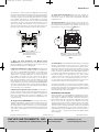
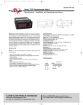
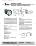
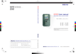
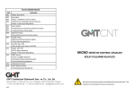
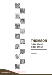
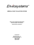
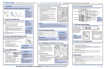
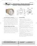
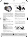
B-33-A:B-33-A
8/14/09
3:02 PM
Page 1
Bulletin B-33-A
Series A3000 Photohelic® Differential Pressure Switch/Gage
Specifications - Installation and Operating Instructions
2-1/2 [63.50]
1/8 FEMALE NPT HIGH
2-1/16 [52.39]
PRESSURE CONNECTION
2 [50.80]
1/8 FEMALE NPT LOW
PRESSURE CONNECTION
1-1/4
[31.75]
Ø4-3/4
[120.65]
3-7/8 SQ
[98.43]
3/4 CONDUIT
CONNECTION
(4) 6-32 HOLES
EQUALLY SPACED ON
A 5-1/8 [130.18] B.C.
Ø4-47/64
[120.25] Ø5
[127.00]
5/8 [15.88]
3-7/8 [98.43]
5-1/8 [130.18]
5/8 [15.88] PANEL
MAX
3/16 [4.76]
6-3/8 [161.93]
4-3/8 [111.13]
(7-5/8 [193.68])
HOUSING REMOVAL
Ø4 [101.60]
FACE
5-1/2 [139.70]
O.D.
MOUNTING
RING
Fig. A
NOTE: Detailed dimension drawings are available from our Customer Service
Dept. for PHOTOHELIC® switch/gages as installed in two optional enclosures.
For weatherproof housing, request no. 13-700132-00. /For explosion-proof
housing, request no. 13-700113-01.
The Series A3000 PHOTOHELIC® Switch/Gage is a versatile
2-in-1 instrument combining a time-proven Magnehelic® differential pressure gage with low/high pressure switches. It is designed
to measure and control positive, negative or differential pressure of
air or other non-combustible, non-corrosive gases. Gage reading
is unaffected by switch operation. Switch set points are easily
adjusted with knobs located on gage face. Applied pressure and
switch set points are fully visible at all times. Deadband is one
pointer width, less than 1% of full scale. Each set point controls a
DPDT relay and both relays can be interlocked to provide variable
deadband control.
SPECIFICATIONS
GAGE SPECIFICATIONS
Service: Air and non-combustible, compatible gases.
Wetted Materials: Consult factory.
Accuracy: ±2% of full scale at 70°F (21.1°C). ±3% on -0 and
±4% on -00 models.
Pressure Limits: -20" Hg. to 25 psig (-0.677 to 1.72 bar). MP
option; 35 psig (2.41 bar), HP option; 80 psig (5.52 bar). 36003S
– 36010S; 150 psig (10.34 bar). 36020S and higher;1.2 x full
scale pressure.
Temperature Limits: 20 to 120°F.
(-6.67 to 48.9°C) Low temperature option available.
Process Connections: 1/8˝ female NPT.
Size: 4˝ (101.6 mm) dial face, 5˝ (127 mm) O.D. x 8-1/4˝ (209.55
mm).
Weight: 4 lb (1.81 kg).
SWITCH SPECIFICATIONS
Switch Type: Each setpoint has 2 Form C relays (DPDT).
Repeatability: ±1% of full scale.
Electrical Rating: 10A @ 28 VDC, 10A @ 120, 240 VAC.
Electrical Connections: Screw terminals. Use 167°F (75°C)
copper conductors only.
Power Requirements: 120 VAC, 50/60 Hz; 240 VAC & 24 VAC
Power optional.
Mounting Orientation: Diaphragm in vertical position. Consult
factory for other position orientations.
Set Point Adjustment: Adjustable knobs on face.
Agency Approvals: UL: File No. E38121, Vol. 1, Sec. 4; CSA:
File No. LR22541-34; CE: EN 61000-6-2: 1999, EN 6100-3-2:
2000, EN 61000-3-3: 2000.
DWYER INSTRUMENTS, INC.
P.O. BOX 373 • MICHIGAN CITY, INDIANA 46361, U.S.A.
INSTALLATION
1. Location: Select a clean, dry, vibration-free location where
ambient temperatures will be between 20 and 120°F (-6.67 and
48.9°C). Tubing supplying pressure to the instrument can be practically any length but long runs will increase response time slightly.
2. Position: The PHOTOHELIC® Switch/Gage is factory calibrated
for use with scale in a vertical plane. Operation at other angles may
affect accuracy and/or require zero adjustment. Most models can
be specially calibrated at the factory for other positions if specified
at time of ordering. Ranges below 1˝ W.C. must be used only with
scale vertical.
3. Mounting: The PHOTOHELIC® Switch/Gage is normally mounted before making electrical connections. The electrical enclosure
is removable at any time regardless of mounting method.
(A) Panel Mounting: Normal mounting is flush or through panel
as shown in Fig. B. Allow 4-3/8˝ (111.13 mm) clearance behind the
unit for removal of electrical enclosure. Make a 4-13/16˝ (122.24
mm) diameter hole in panel. Insert the PHOTOHELIC®
Switch/Gage unit from front of panel and slip mounting ring over
case from behind with stepped side facing rear. Fit the snap ring
into narrow groove at back edge of the bezel. Thread four 6-32 x
1-1/4˝ mounting screws into tapped holes in mounting ring and
seat it against snap ring. Tighten screws against back of panel.
See Fig. B.
SNAP RING GROOVE
Ø4-13/16 [122.24]
HOLE REQUIRED FOR
PANEL MOUNTING
1/2 NPT(M) PRESSURE CONNECTION.
SINGLE HIGH PRESSURE CONNECTION
FOR SERIES 36000S MODELS.
Fig. B
Phone: 219/879-8000
Fax: 219/872-9057
www.dwyer-inst.com
e-mail: [email protected]
B-33-A:B-33-A
8/14/09
3:02 PM
Page 2
(B) Surface Mounting with Remote Relays: Where it is preferred to mount the amplifier-relay unit separate from the gage
assembly, the gage is mounted as shown in Fig. B (without amplifier-relay package) or surface mounted as shown in Fig. C. Use the
dimensions in Fig. D to locate holes.
Fig. E
Fig. C
Ø3/16
TYP 4 PLACES
4-9/32
[108.74]
(3) Ø3/16 [4.76] MOUNTING
HOLES EQUALLY SPACED ON A
401/8 [104.78] B.C.
Ø3/4 [19.05] WIRE
CONNECTION HOLE
1-1/8
[25.58]
4-9/32
[108.74]
5
[127.00] SQ
Fig. F
4. Pneumatic Connections & Zeroing: After installation but
before making pressure connections, set the indicating pointer
exactly on the zero mark, using the zero adjust screw located at
the bottom of the front cover. Note that this adjustment can only
be made with the high and low pressure taps both open to atmosphere.
1-1/8
[28.58]
Fig. D
(C) Remote Relays Mounting: On factory supplied RMR (remote
mounted relay) units, the amplifier-relay package will be furnished
attached to a mounting plate as shown in Fig. E. Use the hole layout in Fig. F for this option. A five foot cable assembly is included
for connecting the two components. Longer cable lengths are
available from the factory.
Connect the high and low pressure taps to positive, negative, or
differential pressure sensing points. Use 1/4˝ diameter metal or
other instrument tubing and 1/8˝ NPT adapters at the PHOTOHELIC® pressure switch/gage. Adapters for rubber or soft plastic
tubing are furnished with the instrument for use where this type of
connection is preferred.
If the PHOTOHELIC® Switch/Gage is not used to sense differential
pressure, one of the pressure taps must be left open to atmosphere. This will allow the reference pressure to enter. In this case,
installation of a Dwyer Instruments, Inc. No. A-331 Filter Vent Plug
or similar fitting in the reference pressure tap is recommended to
reduce the possibility of dust entering the instrument.
NOTE: If the PHOTOHELIC® switch/gage is over pressured, pointer may “jump” from full scale back to zero and remain there until
the excess pressure condition is relieved. Users should be aware
of possible false zero pressure indications under this condition.
B-33-A:B-33-A
8/14/09
3:02 PM
Page 3
ELECTRICAL CONNECTIONS
1. Cover: The amplifier-relay unit has an easy to remove housing.
Remove the three (3) screws as shown in Fig. G and slide the
housing off. Make all the electrical connections before reinstalling
and refastening the housing.
2. Conduit: Electrical access to the connection box portion of the
relay housing is by bottom opening for 3/4˝ conduit. Use of flexible
conduit is recommended. It should be supported from the panel or
other suitable surface to prevent the wiring system from exerting
undue strain on the instrument. See Fig. G.
COVER MOUNTING
SCREWS
Section E contains the power connections for the control unit
transformer primary. The transformer in turn supplies reduced
voltage power for the LED, phototransistor, amplifier unit, and
load relay pull in and hold coils. Connections must always be made
to this section in order to put the unit in operation. Standard units
are designed for 120 VAC input to the transformer. Special units are
also available for other voltages.
Separate Ground Wire attachment is provided for by a No. 6-32
screw on the mounting bracket near the conduit opening. An additional ground wire connection is located on the side of the gage
body for use when the amplifier-relay unit is mounted remotely.
Single Set Point instruments are furnished with the right or high
set point components and circuitry in place. These are connected
to Sections A and B of the terminal board. The left or low set point
components are omitted.
4-3/8 [111.13]
CLEARANCE
FOR COVER REMOVAL
FLEXIBLE CONDUIT
SUPPORT CONDUIT
FROM PANEL
Fig. G
3. Terminal or Connection Board Layout: In Fig. H “Terminal
Board,” Section A contains the connections for the load or slave
relay actuated by the high or right set point. This relay is a double
pole, double throw type. The two right connections are normally
closed, the two middle connections are normally open, and the left
connections are the common pair. The relay is in its normal or DeEnergized position when pressure is below the right hand set
point.
4. Circuit Style: The PHOTOHELIC® SWITCH/GAGE is available
with several factory installed optional internal circuits. They are
identified as to style by a label shown in Fig. J. This label is mounted prominently on the terminal board of each instrument. The letter
H denotes a circuit in which the relay can be made to latch or
remain energized after pressure increase to its set point.
The letter L denotes a circuit in which the relay can be made to
latch or remain de-energized after pressure decrease to its set
point. Two letters are required to fully identify a dual set point unit.
Thus, circuit style HH, which is standard, is a dual set point circuit
which has provisions for latching on pressure increase to either set
point. Single relay unit or L for the special low latch unit. Units for
use with other than standard 120 VAC will be so indicated on the
label.
Section D is exactly the same as Section A except that its load
or slave relay is controlled by the low or left set point. The DeEnergized position is below the left hand pointer set point.
Section B contains the external connections to the holding coil
circuit for the high or right set point relay and Section C contains
similar connections for the low or left set point relay. The function
and use of these connections varies somewhat depending on the
circuit style of the instrument. See paragraphs 5 and 6 for details.
SECTION C
SECTION B
SECTION D
SECTION A
SECTION E
CAUTION: Do not apply electrical current
to terminals in Sections B and C.
Fig. H
Fig. J
5. Dual Set Point Automatic Reset: Circuit Style HH is used for
simple on-off switching applications. To place in service, connect
load circuits to the appropriate terminals in Section A (Fig. H) for the
right set point and Section D for the left set point. Note that the
N.O. contacts are open when the gage pressure pointer is to the
left of the set point pointers. No connections are necessary in
Sections B and C. Make external ground connections as required
and connect power to Section E for the control unit. To use circuit
style LL for automatic reset, a jumper wire must be installed
between the two terminals in Sections B and/or C.
6. Dual Set Point Manual Reset: Circuit Style HH may also be
used for manual reset applications where it is required to maintain
contact on either relay following pressure increase above its set
point. Load or signal connections are made to the appropriate terminals in Sections A and D (as in paragraph 5 above). Connect terminals in Sections B and C through normally closed switches or
push buttons as shown in Fig. K. Use of “dry-circuit” type switches such as a Dwyer Part No. A-601 with paladium, gold, etc. or
rotary wiping action type contacts is recommended. Make external
ground connections as required and connect power to Section E
for the control unit.
B-33-A:B-33-A
8/14/09
3:02 PM
Page 4
Bulletin B-33-A
Circuit style LL is used for manual reset applications which require
that contact be maintained following pressure decrease below the
set point. Load connections are made to the appropriate terminals
in Sections A and D. A normally open type manual reset switch
such as Dwyer® Instruments, Inc. Part No. A-601 is connected to
the terminals in Sections B and C. The circuit must be “armed by
momentarily closing the switch while the black pointer is to the
right of the set point. From that point on, the circuit will latch on
pressure decrease below the set point and remain latched on
pressure increase until manually reset with the optional switch.
11. Single Set Point Special: Manual reset after actuation on
falling pressure can be obtained by using Circuit Style SRL.
Consult the factory for special units and detailed instructions
regarding their use.
12. Placing in Service: In normal operation each relay is de-energized when the pressure applied to the instrument is below its set
point. Special low-latching units will ordinarily have to be reset
before placing on the line in normal operation.
RESET JUMPERS
RESET
NC
RESET
NC
NO
NO
HI
LO
C
NO
NC
NC
NO
C
C
NO
NC
NC
NO
C
L2
1/3 HP*
120 V
LOAD
L1
CAUTION: Do not apply electrical current to terminals in Sections B and C.
Manual Reset with Circuit HH
*Note: For larger motors, use the Photohelic®
Switch/Gage in a maintained contact, 120 Volt
Control or Push Button Circuit of the motor
Fig. K
Fig. L
7. Dual Set Point Automatic and Manual Reset
Combinations: Circuit Style HH may be used with either set point
wired and operating as in paragraph 5 above and the other set
point wired and operating as in paragraph 6.
8. High Low Limit Control - Dual Set Point: Circuit Style HH
may be used to control fans, dampers, pumps, etc., between the
set points of a PHOTOHELIC® Switch/Gage. To accomplish this,
use one set point relay to reset the other as shown in the wiring
diagram Fig. L. In this typical application, the load (for instance a
fan) would be connected to the N.C. contacts for the right set
point relay Section A (Fig. H). On pressure rise to the right set
point, its relay would pull in and hold even though pressure might
then fall below that set point . I the pressure continued to fall to
the left set point, its relay would automatically be DE-ENERGIZED,
return to its normal position and in so doing, open the holding coil
circuit from Section B (Fig. H). The right set point relay would thus
be reset and the cycle could repeat.
9. Dual Set Point Special Purpose Circuits: Circuit Style LL
may be used where manual reset following maintained contact on
pressure decrease to either set point is required. Circuit Styles HL
and LH are combination units. For special combinations of features, special units, and detailed instructions regarding their use,
consult the factory.
10. Single Set Point PHOTOHELIC®: The single set point PHOTOHELIC® Switch/Gage is furnished with the right set point only.
Terminals in Sections A and B (Fig. H) are connected to this relay.
Circuit Style SRH is wired for automatic reset as in paragraph 5
above. Manual reset is accomplished by adding a normally closed
reset switch or push button to the circuit as described in paragraph 6 above.
©Copyright 2009 Dwyer Instruments, Inc.
13. Failure Mode: The PHOTOHELIC® Switch/Gage circuit design
provides certain protection in the event of a loss of pressure or
electrical power. In either case, both relays will de-energize, returning to their normal “zero pressure” state. The exceptions to this are
models with center zero ranges. Because the relays on all standard
models are always energized when the indicating (black) pointer is
to the right of their respective set points, the relay action on loss of
pressure will depend on set point position, since either of them
could be located to the left of zero. As an example; if the left pointer were set at -2 in. w.c. and negative pressure was -3 in. w.c., a
loss of that pressure would allow the black pointer to return to the
center and thus cause the low set point relay to energize.
If the LED should burn out, only the left-low relay will de-energize.
The right-high relay will react as if pressure were above its set point
and will remain energized even though pressure might be below
that setting. In this situation, only termination of electrical power will
allow the right-high relay to de-energize.
MAINTENANCE AND SERVICE
Dwyer Instruments, Inc. PHOTOHELIC® Switch/Gages are precision instruments, expertly assembled and calibrated at the factory.
They require no lubrication or periodic servicing. If the interior is
protected from dust, dirt, corrosive gases and fluids, years of trouble-free service may be expected. Zero adjustment should be
checked and reset occasionally to maintain accuracy. The PHOTOHELIC® Switch/Gage is not field serviceable and should be
returned if repair is needed (field repair should not be attempted
and may void warranty). Be sure to include a brief description of
the problem plus any relevant application notes. Contact customer
service to receive a return goods authorization (RGA) number
before shipping.
Printed in U.S.A. 7/09
DWYER INSTRUMENTS, INC.
P.O. BOX 373 • MICHIGAN CITY, INDIANA 46361, U.S.A.
Phone: 219/879-8000
Fax: 219/872-9057
FR# 13-440202-04 Rev. 5
www.dwyer-inst.com
e-mail: [email protected]