1
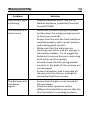
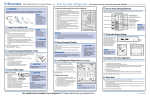
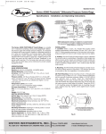
This manual applies to the WT-RC-Ex receiver when used to locate all makes and models of 22 Hz and Wavetrak coded transmitters. The Wavetrak WT-RC-Ex receiver kit comes with the following pieces of equipment: A Wavetrak WT-RC-Ex Receiver An external antenna (optional to use) A 50’ extension cable for the external antenna A hard carrying case Optional accessories available from Wavetrak, which may be included in your kit, are: A strobe attachment (for indicating pig passage remotely by visual indication) Power On/Off Button: Hold this button to turn on or turn off the receiver. Gain Level Indicators: This indicates how sensitive the receiver is to incoming signal. This is adjusted by using the gain buttons on the handle. If LEDs to the left are lit, this indicates lower gain, while LEDs to the right indicate higher gain. If the gain is turned up, the receiver will pick up signal from further away. However, it will also pick up more electrical noise, and could result in a false reading. It is recommended that the gain is set at a point where the signal strength is the highest possible without picking up electrical noise. LED Light Signal Strength Indicators: These will light up when a signal is detected. The LEDs correspond to the numbers on the analog meter, from 1 to 10.The greater the signal, the further to the right the LEDs will light. Analog Meter Signal Strength Indicator: The analog needle will move to indicate how strong the incoming signal is. 0 indicates no signal, and 10 shows maximum signal strength. The numbers on the meter correspond with the LED light signal strength indicators. Transmitter Code Indicators: These LEDs indicate the type of transmitter signal the unit is receiving. “22Hz” indicates that the receiver is detecting a standard 22 Hz transmitter signal. The “A”, “B” and “C” lights indicate that the receiver is detecting a Code A, B, or C transmitter signal, respectively. When receiving a signal from a coded transmitter, the “22Hz” light will light before the appropriate code detect light is lit. Low Battery Indicator: This LED light will flash when the batteries in the receiver are discharged. Put new C cell (LR14) alkaline batteries into the unit as soon as possible. Antenna Attachment Indicator: This LED will light up when an external antenna is plugged into the receiver. WARNING: This indicator will light up whenever an antenna is plugged in and detected. It does not indicate that the antenna is functional. It is possible for the antenna to be detected even if the antenna is damaged and not able to receive a signal. Light Senor: This detects the ambient light conditions. When it is dark, the panel backlight will turn on. Keep this sensor clear of debris, as it will turn the backlight on even when it is not needed. Gain Switch: The up and down arrow buttons on the gain switch controls the gain setting of the electronics. Press up to make the receiver more sensitive, and down to make it less sensitive. Buzzer Off Switch: Press this to toggle whether the buzzer is operational or not. The status of the buzzer is indicated by the word Off being lit in red when the buzzer is disabled. Buzzer Off Indicator: This LED will light up when the buzzer is disabled. To turn on the receiver, press and hold down the power button until the unit powers on. All the front panel lights should turn on briefly as a test, and the ring around the power button will light up to indicate the receiver is on. To turn off the receiver, simply press and hold the power button down again until the power light (the lighted ring around the power button) turns off. The receiver is equipped with an internal antenna, so you can begin tracking right away. No attachments are needed. The receiver gain is controlled with the gain adjustment buttons on the top of the receiver handle. Pressing the red up arrow will increase the gain; the blue down arrow will decrease the gain. The current gain setting is indicated on the row of lights labeled “GAIN”, with the rightmost light being full gain, and the leftmost being no gain. When you turn the receiver on it will return to the last gain setting used. If a signal is received, it will be shown on the signal meter. The signal lights above the meter follow the meter’s position. If the signal is a transmitter’s 22Hz signal, the 22 Hz light will turn on and the buzzer will sound. If the signal is a Wavetrak coded signal (from a coded transmitter) the appropriate code will light. For example, once a Wavetrak code C transmitter is in range, it will be indicated by the 22Hz light and the buzzer turning on for approximately ½ a second, followed by the C light briefly lighting to indicate that it has a C code. Then after a brief pause the sequence will repeat as long as the transmitter is in range. The buzzer can be silenced, if desired. Use the buzzer off button on the handle. On power up, the receiver keeps the last setting. There are two jacks located on the front of the receiver. The 3 connector jack is for an optional strobe attachment, and the 4 connector jack is for connecting an external antenna or external antenna extension cable. Both receptacles are designed so that each attachment will only plug into the correct jack. The included external antenna can be used to both increase range and more effectively pinpoint a transmitter’s location. To use it, plug it into the antenna connector on the front end of the receiver. You can also attach the extension cable, to increase the cable length to the antenna. When the antenna is connected and detected, the receiver will switch from the internal antenna to the external one. The ANT light on the front panel will light up, indicating that the receiver senses the external antenna and has switched over. WARNING: This indicator will light up whenever an antenna is plugged in and detected. It does not indicate that the antenna is functional. It is possible for the antenna to be detected even if the antenna is damaged and not able to receive a signal. Functional tests to check a transmitter and receiver’s operation are always recommended. To connect the optional strobe attachment, simply plug it into the front end panel, as you do with the external antenna. It is best to check the operation of the strobe with a functional transmitter, to make sure that it is connected properly and in working order. The strobe will only flash when the 22Hz light is on and the buzzer sounds on the receiver. The backlight on the receiver, which backlights both the meter and panel text will turn on automatically when the ambient light becomes dim. WARNING: NEVER UNSCREW OR OPEN THE BATTERY COMPARTMENT WHILE IN A HAZARDOUS ENVIRONMENT. 1) Before replacing the battery compartment visually inspect the gasket to ensure a proper seal. 2) Once batteries are installed, ensure all four screws are tight, securing the battery box to the chassis. WARNING: NEVER UNSCREW OR OPEN THE BATTERY COMPARTMENT WHILE IN A HAZARDOUS ENVIRONMENT To change the batteries, unscrew the 4 screws located on the battery box (the back end of the receiver). Remove the battery box from the receiver. Do not unscrew the 4 screws located on the front of the receiver (near the meter) – there are no user serviceable parts inside. Doing this can void your warranty. Replace the 8 C cell alkaline (LR14) batteries with fresh batteries of the same type. Wavetrak recommends using Duracell Procell PC1400 batteries. Ensure that the batteries are inserted in the orientation marked on the battery holders, and that all of the batteries are making contact. Before replacing the battery box and refastening the 4 screws, check the condition of the battery box gasket that seals to the face of the receiver. If it is damaged, the unit will no longer be weather-tight; contact Wavetrak for a replacement gasket. Wavetrak can check the calibration of the Receiver and recalibrate as necessary. Contact Wavetrak for more information. Power up the transmitter. Before placing it into use in the pipeline, a function test should be conducted with the receiver to ensure that the correct signal strength is being generated by the transmitter, and that the receiver is operational. Once the open air test is complete, fasten the transmitter to the tool. When installing the transmitter into the pig, ensure that it is placed cap end first. Also, check that there is enough clearance between the transmitter and the pipe wall so that there is no danger of the transmitter rubbing on the pipe. (Refer to: MOUNTING PRECATIONS in the WT-Ex Transmitter User Manual). Locate the transmitter and ensure transmitter is operational prior to launch. (Refer to: LOCATING THE TRANSMITTER AT THE LAUNCH / TRAP). WARNING: WHEN MOUNTING A WAVETRAK TRANSMITTER, ENSURE THAT THE TRANSMITTER WILL AT NO TIME CONTACT THE PIPE WALL WHILE THE PIG IS TRAVELLING THROUGH THE PIPELINE. THIS WILL CAUSE DAMAGE AND WILL VOID THE WARRANTY. FOR Ex MODEL TRANSMITTERS, THIS WILL ALSO CAUSE THE TRANSMITTER’S EXPLOSION PROOF FEATURES TO LOSE THEIR EFFECTIVENESS. To detect tool passage, the external antenna (or receiver itself if using the internal antenna) should be placed parallel with the pipeline and on top of the pipeline location waiting for the tool to pass. The receiver gain should be set as high as possible without detecting interference or noise. When the tool passes underneath the antenna, the operator should be able to see the transmitter signal rise in strength on the receiver. The 22Hz light and any appropriate code lights will turn on (to match either a standard, continuous, or coded transmitter), and the buzzer will sound. As the transmitter continues on down the pipeline the signal strength will decrease until the transmitter is out of range. When the signal is at its peak is when the transmitter is directly below the antenna. When working near noise generated by neighboring electrical lines, large electrical apparatus, or erratic movements of the antenna, the technician should recognize that these signals can trigger the 22 Hz detect light and buzzer, as well as the A, B and C code lights of the receiver. If the receiver seems to have picked up a stray signal then simply stop and steady the receiver. Check to see if there is the distinctive solid tone or beat of the transmitter. If no solid tone or pulsing beat is detected then most likely noise triggered the receiver and the operator should continue the search. When walking with the receiver to locate a transmitter (such as to locate a stuck pig), the external antenna is least likely to pick up noise when gently suspending the antenna by holding the cable, allowing the antenna to point to the ground. As the technician approaches the transmitter with the antenna in a vertical position over the line, the signal level indicated by both the meter and lights will increase until the antenna is directly over the transmitter. (Detection could start well over 30 feet from the transmitter’s actual location, depending on the type of transmitter). When the antenna is exactly over the transmitter a sharp signal loss or “null” will occur. As the antenna is moved on either side of the null point the signal strength will again increase. The receiver signal gain should be adjusted to suit the strength of the transmitter and distance between transmitter and receiver. In most cases, technicians find it convenient to use the internal antenna to locate the transmitter at launch and trap facilities. Depending on facility interference, the receiver is usually set on a 3/4 gain and pointed in the direction of the where the transmitter is thought to be. With a slow sweeping motion and advancing towards the transmitter the technician watches the meter or signal lights for the greatest signal, the technician is then able to identify the direction in which the greatest gain comes from. While moving closer to the transmitter the technician will likely be required to turn down the gain due to the proximity of the signal. Move the receiver from side to side or back and forth with receiver or external antenna (if used) pointing perpendicular to the tool. When the receiver is perpendicular to and exactly in the middle of the transmitter a null (sharp loss) in the signal strength will be evident. In fact, at that precise position the receiver may indicate that there is no signal. Specification Value Operating Voltage - 12 volts Batteries - 8 x C Cell Alkaline (LR14) Wavetrak Recommends: Duracell Procell PC1400 Low Voltage Light - 9 volts Battery Life - Approx. 200 hours (with backlight on 50% of the time). (Battery life varies with signal detection and usage) Operating Temperature - -20oC to +50oC Weight - 5 lbs. Receiver Dimensions - 12.1” x 4.6” x 2.8” (with handle) 30.7 cm x 11.7 cm x 7.1 cm (with handle) Materials - Aluminum body with ABS-PC handle and Polycarbonate internals. Meter lens is PMMA-Acrylic. Polypropylene battery holder. Antenna Dimensions - 13.8” x 1.2” dia. (without strain relief) Cable Lengths - Antenna: 3’ (minimum) Extension Cable: approx. 50’ Problem Solution Low battery light is blinking: - Replace batteries with C cell (LR14) alkaline batteries, preferably Duracell Procell PC1400. The Receiver will not turn on: - Make sure you are holding the power button down for a long enough period of time (one second). Ensure that the unit has fresh batteries installed properly with correct polarity and making good contact. Make sure that the batteries are touching each other and the springs in the battery holders. Try to wiggle the batteries to ensure they are contacting each other and the springs. Visually check that the spring loaded contacts in the body of the receiver are not damaged. Ensure the battery box is inserted all the way into the chassis, and tightly secured with all four screws. - - - - The Receiver will not detect signal: - Ensure that the gain is not turned all the way down. Check receiver operation with a different transmitter to ensure that the first transmitter is working properly. The Receiver will not detect signal with the external Antenna connected: - - - Ensure that the gain is not turned all the way down. Verify that the ANT light is lit on the receiver, indicating antenna connection. If ANT light is not lit, ensure that all the connections are secure, especially if using an extension cable. Check the Antenna cable and extension cable for breaks, nicks or tight bends which could have damaged the conductors. Unplug the Antenna and check Receiver operation using the internal antenna. If the internal antenna functions, check operation with a different external antenna. If still not functioning, contact Wavetrak. Backlight stays on when it is not dark: - Ensure that the backlight sensor on the panel, located under the 22 Hz light, is free of blockage by dirt or debris. The Receiver powers on and then off again quickly: - Check that the batteries are fresh. This will happen with discharged batteries, especially in very cold temperatures. The information contained in this manual is subject to change without notice. This manual is copyright © 2013 Wavetrak Electronics Ltd. All rights reserved. To the maximum extent permitted by law, Wavetrak Electronics Ltd. is not responsible for any direct, special, incidental, or consequential damages by the operator(s), the operator’s employer, or any party, resulting from any breach of warranty, use or misuse of this product, or under any other legal theory (including, but not limited to, lost profits, downtime, goodwill and damage to or replacement of equipment and property), even if Wavetrak Electronics Ltd. has been advised of the possibility of such damages. (Some jurisdictions do not allow the exclusion or limitation of incidental or consequential damages, so the above limitations may not apply.) All Wavetrak Electronics equipment is proudly backed by a one (1) year warranty against manufacturing defects. For more details see http://www.wavetrak.ca/pdf/Wavetrak Warranty Card.pdf