1
GE Healthcare
Discovery* Dicom Conformance Statement
for DICOM v3.0 (ID/Net v3.0)
*
Refer to section 1 for a list of products in the Discovery family
to which this Conformance Statement applies.
5161694-100
Rev 1
© 2005, General Electric Company,
All Rights Reserved
GE HEALTHCARE
DIRECTION 5161694-100, REV 1
DISCOVERY* DICOM CONFORMANCE STATEMENT
Page Left Intentionally Blank
2 of 169
GE HEALTHCARE
DIRECTION 5161694-100, REV 1
DISCOVERY* DICOM CONFORMANCE STATEMENT
LEGAL NOTES
TRADEMARKS
All products and their name brands are trademarks of their respective holders.
OMISSIONS & ERRORS
Customers, please contact your GE Sales or Service representatives.
GE personnel, please use the GE Healthcare PQR Process to report all omissions, errors, and
defects in this publication.
Copyrights
All Material Copyright (c) 2005 by the General Electric Company, All rights reserved.
3 of 169
GE HEALTHCARE
DIRECTION 5161694-100, REV 1
DISCOVERY* DICOM CONFORMANCE STATEMENT
Important Precautions
WARNING
AVERTISSEMENT
WARNUNG
AVISO
ATENÇÃO
This Service Manual is available in English only.
If a customer’s service provider requires a language other than English, it is the
customer’s responsibility to provide translation services.
Do not attempt to service the equipment unless this service manual has been
consulted and is understood.
Failure to heed this Warning may result in injury to the service provider, operator
or patient from electric shock, mechanical or other hazards.
Ce Manuel de maintenance n’est disponible qu’en anglais.
Si le technicien du client a besoin de ce manuel dans une autre langue que
l’anglais, c’est au client qu’il incombe de le faire traduire.
Ne pas tenter d’intervention sur les équipements tant que le manuel Service n’a
pas été consulté et compris.
Le non-respect de cet avertissement peut entraîner chez le technicien,
l’opérateur ou le patient des blessures dues à des dangers électriques,
mécaniques ou autres.
Dieses Kundendienst-Handbuch existiert nur in englischer Sprache.
Falls ein fremder Kundendienst eine andere Sprache benötigt, ist es Aufgabe
des Kunden für eine entsprechende Übersetzung zu sorgen.
Versuchen Sie nicht, das Gerät zu reparieren, bevor dieses KundendienstHandbuch zu Rate gezogen und verstanden wurde.
Wird diese Warnung nicht beachtet, so kann es zu Verletzungen des
Kundendiensttechnikers, des Bedieners oder des Patienten durch elektrische
Schläge, mechanische oder sonstige Gefahren kommen.
Este Manual de Servicio sólo existe en inglés.
Si algún proveedor de servicios ajeno a GEMS solicita un idioma que no sea el
inglés, es responsabilidad del cliente ofrecer un servicio de traducción.
No se deberá dar servicio técnico al equipo, sin haber consultado y
comprendido este manual de servicio.
La no observancia del presente aviso puede dar lugar a que el proveedor de
servicios, el operador o el paciente sufran lesiones provocadas por causas
eléctricas, mecánicas o de otra naturaleza.
Este Manual de Assistência Técnica só se encontra disponível em Inglês.
Se qualquer outro serviço de assistência técnica, quE não a GEMS, solicitar
estes manuais noutro idioma, é da responsabilidade do cliente fornecer os
serviços de tradução.
Não tente reparar o equipamento sem ter consultado e compreendido este
Manual de Assistência Técnica.
O não cumprimento deste aviso pode por em perigo a segurança do técnico,
operador ou paciente devido a‘ choques elétricos, mecânicos ou outros.
4 of 169
GE HEALTHCARE
DIRECTION 5161694-100, REV 1
AVVERTENZA
DISCOVERY* DICOM CONFORMANCE STATEMENT
Il presente manuale di manutenzione è disponibile soltanto in inglese.
Se un addetto alla manutenzione esterno alla GEMS richiede il manuale in una
lingua diversa, il cliente è tenuto a provvedere direttamente alla traduzione.
Si proceda alla manutenzione dell’apparecchiatura solo dopo aver consultato il
presente manuale ed averne compreso il contenuto.
Non tenere conto della presente avvertenza potrebbe far compiere operazioni da
cui derivino lesioni all’addetto alla manutenzione, all’utilizzatore ed al paziente
per folgorazione elettrica, per urti meccanici od altri rischi.
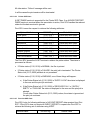
REVISON HISTORY
REV.
1
DATE
1/14/2005
REASON FOR CHANGE
Added section 8 describing the Grayscale
Presentation State implementation.
Removed section B.1.9 GEMS_CT_VES_01
Updated section 7 PPS.
Removed section B.2 MR Private Data
Elements
5 of 169
GE HEALTHCARE
DIRECTION 5161694-100, REV 1
DISCOVERY* DICOM CONFORMANCE STATEMENT
Page Left Intentionally Blank
6 of 169
TABLE OF CONTENTS
1
SECTION 1 – INTRODUCTION ....................................................................................................14
1.1
1.2
1.3
1.4
1.5
1.6
1.7
1.8
2
OVERVIEW................................................................................................................................14
OVERALL CONFORMANCE STATEMENT DOCUMENTATION STRUCTURE.........................................15
INTENDED AUDIENCE ................................................................................................................16
SCOPE AND FIELD OF APPLICATION ...........................................................................................17
IMPORTANT REMARKS ...............................................................................................................17
REFERENCES ...........................................................................................................................18
DEFINITIONS .............................................................................................................................18
SYMBOLS AND ABBREVIATIONS ..................................................................................................18
SECTION 2 – NETWORK CONFORMANCE STATEMENT ........................................................19
2.1
INTRODUCTION .........................................................................................................................19
2.2
IMPLEMENTATION MODEL ..........................................................................................................19
2.2.1
Application Data Flow Diagram ..................................................................................20
2.2.2
Functional Definition of AE’s.......................................................................................21
2.2.3
Sequencing of Real-World Activities...........................................................................22
2.3
AE SPECIFICATIONS .................................................................................................................22
2.3.1
DICOM Server AE Specification .................................................................................22
2.3.1.1
Association Establishment Policy .............................................................................................23
2.3.1.1.1
General ...........................................................................................................................23
2.3.1.1.2
Number of Associations ..................................................................................................23
2.3.1.1.3
Asynchronous Nature......................................................................................................24
2.3.1.1.4
Implementation Identifying Information ...........................................................................24
2.3.1.2
Association Initiation by Real-World Activity.............................................................................24
2.3.1.2.1
Push Image(s) to Remote AE .........................................................................................24
2.3.1.2.2
Query Remote AE...........................................................................................................26
2.3.1.2.3
Get Image(s) from Remote AE........................................................................................28
2.3.1.2.4
Real-World Activity: Verify (DICOM Ping) .......................................................................29
2.3.1.2.5
Real-World Activity: Storage Commitment ......................................................................30
2.3.1.3
Association Acceptance Policy .................................................................................................30
2.3.1.3.1
Receive Image(s) ............................................................................................................31
2.3.1.3.2
Verification Request from Remote AE.............................................................................33
2.3.1.3.3
Query Request from Remote AE ....................................................................................33
2.3.1.3.4
Retrieve Request From Remote AE................................................................................36
2.4
COMMUNICATION PROFILES ......................................................................................................37
2.4.1
Supported Communication Stacks (parts 8,9)............................................................37
2.4.2
TCP/IP Stack ..............................................................................................................37
2.4.2.1
Physical Media Support ............................................................................................................37
2.4.3
Point-to-Point Stack ....................................................................................................37
2.5
EXTENSIONS / SPECIALIZATIONS / PRIVATIZATIONS .....................................................................37
2.5.1
Specialized Information Object Definition ...................................................................37
2.5.2
Private Data Elements ................................................................................................38
2.6
CONFIGURATION .......................................................................................................................38
2.6.1
AE Title/Presentation Address Mapping .....................................................................38
2.6.2
Configurable Parameters ............................................................................................38
2.7
SUPPORT OF EXTENDED CHARACTER SETS ...............................................................................39
3
MEDIA STORAGE CONFORMANCE STATEMENT ...................................................................40
3.1
INTRODUCTION .........................................................................................................................40
3.2
IMPLEMENTATION MODEL: MOD ARCHIVE SERVER ....................................................................40
3.2.1
Application Data Flow Diagram ..................................................................................40
3.2.2
Functional Definitions of AE's .....................................................................................41
3.2.3
Sequencing of Real World Activities...........................................................................41
3.2.4
File Meta Information for Implementation Class and Version.....................................41
3.3
AE SPECIFICATIONS .................................................................................................................42
3.3.1
Media Archive Specification........................................................................................42
3.3.1.1
File Meta Information for the Application Entity........................................................................ 42
3.3.1.2
Real World Activities ................................................................................................................ 43
3.3.1.2.1
Real World Activity: Create Media Request ................................................................... 43
3.3.1.2.2
Real World Activity: Display Directory ............................................................................ 43
3.3.1.2.3
Real World Activity: Copy to Local Storage.................................................................... 43
3.3.1.2.4
Real World Activity: Update Media ................................................................................. 44
3.4
STANDARD, AUGMENTED AND PRIVATE APPLICATION PROFILES ..................................................44
3.4.1
Class and Profile Identification ...................................................................................44
3.4.2
Clinical Contexts .........................................................................................................45
3.4.2.1
Roles and Service Class Options ............................................................................................ 45
3.4.2.1.1
File Set Creator .............................................................................................................. 45
3.4.2.1.2
File Set Reader .............................................................................................................. 45
3.4.2.1.3
File Set Updater ............................................................................................................. 46
3.4.3
Standard Application Profiles......................................................................................46
3.4.3.1
STD-CTMR-MOD12 Class Profile ........................................................................................... 46
3.4.3.1.1
SOP Classes and Transfer Syntax’s .............................................................................. 46
3.4.3.1.2
Physical Media and Media Formats ............................................................................... 47
3.4.3.1.3
Logical Format................................................................................................................ 47
3.4.3.1.4
Directory Information in DICOMDIR ............................................................................... 48
3.4.3.1.5
Other Parameters........................................................................................................... 49
3.4.3.1.6
Image Attribute Values ................................................................................................... 49
3.4.3.2
STD-CTMR-MOD23 Class Profile ........................................................................................... 49
3.4.3.2.1
SOP Classes and Transfer Syntax’s .............................................................................. 49
3.4.3.2.2
Physical Media and Media Formats ............................................................................... 49
3.4.3.2.3
Logical Format................................................................................................................ 50
3.4.3.2.4
Directory Information in DICOMDIR ............................................................................... 50
3.4.3.2.5
Other Parameters........................................................................................................... 51
3.4.4
Private Application Profiles .........................................................................................51
3.4.4.1
PRI-CTMR-MOD12 Class Profile............................................................................................. 51
3.4.4.1.1
SOP Classes and Transfer Syntax................................................................................. 51
3.4.4.1.2
Physical Media and Media Formats ............................................................................... 52
3.4.4.1.3
Logical Format................................................................................................................ 52
3.4.4.1.4
Directory Information in DICOMDIR ............................................................................... 52
3.4.4.1.5
Other Parameters........................................................................................................... 52
3.5
EXTENSIONS, SPECIALIZATIONS AND PRIVATIZATION OF SOP CLASSES AND TRANSFER SYNTAX ..53
3.5.1
Extensions, Specialization’s and Privatization’s of SOP Classes...............................53
3.5.1.1
3.5.1.2
SOP Specific Conformance Statement for CT SOP Class....................................................... 53
SOP Specific Conformance Statement for MR SOP Class...................................................... 53
3.5.2
Private Transfer Syntax Specification.........................................................................53
3.6
CONFIGURATION .......................................................................................................................55
3.7
SUPPORT OF EXTENDED CHARACTER SETS ...............................................................................55
4
PRINT SCU CONFORMANCE......................................................................................................56
4.1
INTRODUCTION .........................................................................................................................56
4.2
IMPLEMENTATION MODEL: PRINT SCU .....................................................................................56
4.2.1
Application Data Flow Diagram ..................................................................................56
4.2.2
Functional Definition of AE’s .......................................................................................56
4.2.3
Sequencing of Real-World Activities...........................................................................56
4.3
AE SPECIFICATIONS..................................................................................................................58
4.3.1
DICOM Print SCU AE Specification............................................................................58
4.3.1.1
Association Establishment Policy ............................................................................................ 58
4.3.1.1.1
General .......................................................................................................................... 58
4.3.1.1.2
Number of Associations ................................................................................................. 58
4.3.1.1.3
Asynchronous Nature..................................................................................................... 58
4.3.1.1.4
Implementation identifying information ........................................................................... 58
4.3.1.2
Association Establishment Policy ............................................................................................ 59
4.3.1.2.1
Real World Activity ......................................................................................................... 59
4.3.1.2.2
SOP Specific Conformance Statement .......................................................................... 60
4.3.1.3
Association Acceptance Policy ................................................................................................ 64
4.4
COMMUNICATION PROFILES.......................................................................................................64
4.4.1
Supported Communication Stacks (parts 8,9) ............................................................64
4.4.1.1
TCP/IP Stack ........................................................................................................................... 64
4.4.1.1.1
4.4.1.1.2
API ..................................................................................................................................64
Physical Media Support ..................................................................................................64
4.5
STANDARD EXTENDED / SPECIALIZED / PRIVATE SOPS ..............................................................64
4.6
CONFIGURATION .......................................................................................................................64
4.6.1
AE Title/Presentation Address Mapping .....................................................................64
4.6.2
Configurable Parameters ............................................................................................64
4.7
SUPPORT OF EXTENDED CHARACTER SET .................................................................................65
5
DICOM STORAGE COMMITMENT SCU CONFORMANCE ......................................................66
5.1
INTRODUCTION .........................................................................................................................66
5.2
IMPLEMENTATION MODEL ..........................................................................................................66
5.2.1
Application data flow diagram.....................................................................................66
5.2.2
Functional definitions ..................................................................................................67
5.2.3
Sequencing of real-world activities .............................................................................67
5.3 AE SPECIFICATIONS ......................................................................................................67
5.3.1
DICOM Storage Commitment SCU specifications .....................................................67
5.3.1.1
Association establishment policies ...........................................................................................67
5.3.1.1.1
General ...........................................................................................................................67
5.3.1.1.2
Number of associations...................................................................................................68
5.3.1.1.3
Asynchronous nature ......................................................................................................68
5.3.1.1.4
Implementation identifying information............................................................................68
Note: CT AE and PET AE are the two different entities generating images. .............................................68
5.3.1.2
Association initiation policy .......................................................................................................68
5.3.1.3
Real World Activity ...................................................................................................................68
5.3.1.3.1
Associated Real World Activity - ”Save exam/series” .....................................................68
5.3.1.3.2
Associated Real World Activity - ”Auto Archive exam/series” .........................................68
5.3.1.4
Proposed Presentation Contexts ..............................................................................................68
5.3.1.5
Request Processing .................................................................................................................69
5.3.1.6
Response Processing...............................................................................................................70
5.3.1.6.1
Commit response with SUCCESS status........................................................................70
5.3.1.6.2
Commit response with FAILURE status ..........................................................................70
5.3.1.7
Association Acceptance Policy .................................................................................................71
5.4
COMMUNICATION PROFILES ......................................................................................................71
5.4.1
Supported Communication Stacks (parts 8,9)............................................................71
5.4.2
TCP/IP Stack ..............................................................................................................71
5.4.2.1
Physical Media Support ............................................................................................................71
5.4.3
Point-to-Point Stack ....................................................................................................71
5.5
EXTENSIONS/SPECIALIZATIONS/PRIVATIZATIONS.........................................................72
5.6
CONFIGURATION .................................................................................................................72
5.6.1
AE Title/Presentation Address Mapping .....................................................................72
5.6.2
Configurable Parameters ............................................................................................72
5.7
SUPPORT OF EXTENDED CHARACTER SETS ...............................................................................72
6
MODALITY WORK LIST INFORMATION MODEL DEFINITION.................................................73
6.1
INTRODUCTION .........................................................................................................................73
6.2
IMPLEMENTATION MODEL ..........................................................................................................73
6.2.1
Application Data Flow Diagram ..................................................................................73
6.2.2
Functional definitions ..................................................................................................74
6.2.3
Sequencing of Real-World Activities...........................................................................74
6.3
AE SPECIFICATIONS .................................................................................................................74
6.3.1
Worklist Server AE Specification ................................................................................74
6.3.1.1
Association Establishment Policies ..........................................................................................74
6.3.1.1.1
General ...........................................................................................................................74
6.3.1.1.2
Number of Associations ..................................................................................................75
6.3.1.1.3
Asynchronous Nature......................................................................................................75
6.3.1.1.4
Implementation Identifying Information ...........................................................................75
6.3.1.2
Association Initiation Policy ......................................................................................................75
6.3.1.2.1
Real-World Activity: Worklist Query ................................................................................75
6.3.1.3
Association Acceptance Policy .................................................................................................78
6.4
COMMUNICATION PROFILES ......................................................................................................78
6.4.1
6.4.2
6.4.3
6.4.3.1
6.4.3.2
Supported Communication Stacks (PS 3.8, PS 3.9) ..................................................78
OSI Stack ....................................................................................................................78
TCP/IP Stack ..............................................................................................................78
API ........................................................................................................................................... 78
Physical Media Support ........................................................................................................... 78
6.4.4
Point-to-Point Stack ....................................................................................................78
6.5
EXTENSIONS / SPECIALIZATIONS / PRIVATIZATIONS .....................................................................79
6.5.1
Standard Extended /Specialized/Private SOPs ..........................................................79
6.5.2
Private Transfer Syntaxes...........................................................................................79
6.6
CONFIGURATION .................................................................................................................79
6.6.1
AE Title/Presentation Address Mapping .....................................................................79
6.6.2
Configurable Parameters ............................................................................................79
6.7
SUPPORT OF EXTENDED CHARACTER SETS ...............................................................................80
6.8
MODALITY WORKLIST INFORMATION MODEL DEFINITION .............................................................80
6.8.1
Introduction .................................................................................................................80
6.8.2
Modality Worklist Information Model Description........................................................80
6.8.3
Modality Worklist Information Model Entity-Relationship Model.................................80
6.8.4
Entity Descriptions ......................................................................................................81
6.8.4.1
6.8.4.2
6.8.4.3
6.8.4.4
6.8.4.5
6.8.5
6.8.6
6.8.7
6.8.8
6.8.9
6.8.9.1
6.8.9.2
6.8.10
6.8.10.1
6.8.11
6.8.11.1
6.8.12
6.8.12.1
6.8.12.2
6.8.12.3
6.8.12.4
6.8.13
6.8.13.1
6.8.13.2
6.8.13.3
6.8.13.4
Scheduled Procedure Step ...................................................................................................... 81
Requested Procedure Entity Description ................................................................................. 81
Imaging Service Request Entity Description ............................................................................ 81
Visit Entity Description ............................................................................................................. 82
Patient Entity Description......................................................................................................... 82
ModalityWorklist Mapping of DICOM Entities .............................................................82
Information Model Module Table ................................................................................82
Information Model Keys ..............................................................................................83
Supported Matching....................................................................................................84
Scheduled Procedure Step Entity...............................................................................84
SOP Common Module ............................................................................................................. 84
Scheduled Procedure Step Module ......................................................................................... 85
Requested Procedure Entity .......................................................................................86
Requested Procedure Module ................................................................................................. 86
Imaging Service Request Entity..................................................................................86
Imaging Service Request Module ............................................................................................ 86
Visit Entity ...................................................................................................................87
Visit Identification ..................................................................................................................... 87
Visit Status............................................................................................................................... 87
Visit Relationship ..................................................................................................................... 88
Visit Admission ........................................................................................................................ 88
Patient Entity...............................................................................................................88
Patient Relationship ................................................................................................................. 88
Patient Identification ................................................................................................................ 88
Patient Demographic ............................................................................................................... 89
Patient Medical ........................................................................................................................ 89
6.9
PRIVATE DATA DICTIONARY .......................................................................................................89
6.10 C-FIND REQUEST MESSAGE ....................................................................................................90
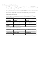
6.11 USE OF SPECIFIC DICOM DATA ................................................................................................92
6.12 SETTING USER PREFERENCES ..................................................................................................93
6.12.1
Setting “Use MWL Study UID “ Option .......................................................................93
6.12.2
Setting Custom Query Option.....................................................................................93
7
PERFORMED PROCEDURE STEP CONFORMANCE STATEMENT ........................................94
7.1
INTRODUCTION .........................................................................................................................94
7.2
IMPLEMENTATION MODEL ..........................................................................................................94
7.2.1
Application Data Flow Diagram ..................................................................................94
7.2.2
Functional Definition of AEs........................................................................................95
7.2.3
Sequencing of Real-World Activities...........................................................................95
7.2.3.1
7.2.3.2
7.2.3.3
PPS from Acquisition System with MWL data.......................................................................... 95
PPS from acquisition system without MWL data...................................................................... 96
PPS from post-processing system ........................................................................................... 97
7.3
AE SPECIFICATION ...................................................................................................................97
7.3.1
PPS Server AE Specification......................................................................................97
7.3.1.1
Association Establishment Policies ..........................................................................................97
7.3.1.1.1
General ...........................................................................................................................97
7.3.1.1.2
Number of Associations ..................................................................................................98
7.3.1.1.3
Asynchronous Nature......................................................................................................98
7.3.1.1.4
Implementation Identifying information ...........................................................................98
7.3.1.2
Association Initiation Policy ......................................................................................................98
7.3.1.2.1
Real-World Activity: Performed Procedure Step creation and update.............................98
7.3.1.3
Association Acceptance Policy .................................................................................................99
7.4
COMMUNICATION PROFILES..............................................................................................99
7.4.1
Supported Communication Stacks (PS 3.8) ...............................................................99
7.4.2
OSI Stack....................................................................................................................99
7.4.3
TCP/IP Stack ..............................................................................................................99
7.4.3.1
7.4.3.2
API............................................................................................................................................99
Physical Media Support ............................................................................................................99
7.4.4
Point-to-Point Stack ..................................................................................................100
7.5
EXTENSIONS/SPECIALIZATION/PRIVATIZATION ...........................................................100
7.5.1
Standard Extended/Specialized/Private SOPs.........................................................100
7.5.2
Private Transfer Syntaxes ........................................................................................100
7.6
CONFIGURATION ...............................................................................................................100
7.6.1
AE Title/Presentation address Mapping ...................................................................101
7.6.2
Configurable Parameters ..........................................................................................101
7.7
SUPPORT OF EXTENDED CHARACTER SETS ................................................................101
7.8
N-CREATE & NSET REQUEST MESSAGE ........................................................................101
7.9
ERROR HANDLING AND RECOVERY................................................................................103
7.10 USE OF SPECIFIC DICOM DATA ..............................................................................................104
7.11 USE OF SPECIFIC DICOM DATA........................................................................................106
7.11.1
Patient Level .............................................................................................................106
7.11.2
Study Level ...............................................................................................................106
7.11.3
Series Level ..............................................................................................................107
8
GRAYSCALE PRESENTATION STATE ....................................................................................107
8.1
INTRODUCTION .......................................................................................................................107
8.2
IMPLEMENTATION MODEL ........................................................................................................108
8.2.1
Application Data Flow Diagram ................................................................................108
8.2.2
Functional Definition of AEs......................................................................................109
8.2.3
Sequencing of Real-World Activities.........................................................................109
8.2.3.1
8.2.4
GSPS Acquisition System with MWL data..............................................................................109
GSPS Server AE Specification .................................................................................109
8.2.4.1
Association Establishment Policies ........................................................................................109
8.2.4.1.1
General .........................................................................................................................109
8.2.4.1.2
Number of Associations ................................................................................................110
8.2.4.1.3
Asynchronous Nature....................................................................................................110
8.2.4.1.4
Implementation Identifying information .........................................................................110
8.2.4.2
Association Initiation Policy ....................................................................................................110
8.2.4.2.1
Real-World Activity: GSPS............................................................................................110
8.2.4.3
Association Acceptance Policy ...............................................................................................111
8.3
COMMUNICATION PROFILES............................................................................................111
8.3.1
Supported Communication Stacks (PS 3.8) .............................................................111
8.3.2
OSI Stack..................................................................................................................111
8.3.3
TCP/IP Stack ............................................................................................................111
8.3.3.1
8.3.3.2
API..........................................................................................................................................111
Physical Media Support ..........................................................................................................111
8.3.4
Point-to-Point Stack ..................................................................................................111
8.4
EXTENSIONS/SPECIALIZATION/PRIVATIZATION ...........................................................111
8.4.1
Standard Extended/Specialized/Private SOPs.........................................................111
8.4.2
Private Transfer Syntaxes ........................................................................................111
8.5
CONFIGURATION ...............................................................................................................112
8.5.1
AE Title/Presentation address Mapping ...................................................................113
Configurable Parameters ..........................................................................................113
8.5.2
8.6
SUPPORT OF EXTENDED CHARACTER SETS ................................................................113
8.7
ERROR HANDLING AND RECOVERY................................................................................113
8.8
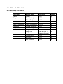
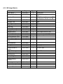
USE OF SPECIFIC DICOM DATA ..............................................................................................114
8.9
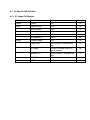
IMAGE HEADER CHANGES SUPPORTING GSPS........................................................................118
8.9.1
Request Attributes Sequence ...................................................................................118
8.9.2
Accession Number....................................................................................................119
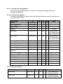
A.1 CT SPECIFIC IOD DEFINITION .................................................................................................120
A.1.1
CT Image IOD Modules ............................................................................................120
A.1.2
CT Image Module .....................................................................................................120
A.1.2.1
Implementation Specific details ............................................................................................. 122
A.2 MR SPECIFIC IOD DEFINITION.................................................................................................123
A.2.1
MR Image IOD Modules ...........................................................................................123
A.2.2
MR Image Module.....................................................................................................124
A.3 SC SPECIFIC IOD DEFINITION .................................................................................................125
A.3.1
SC Image IOD Modules ............................................................................................125
A.4 STANDALONE OVERLAY SPECIFIC IOD DEFINITION ...................................................................126
A.4.1
Standalone Overlay Image IOD Modules .................................................................126
A.5 CT/MR/SC/STANDALONE OVERLAY IOD COMMON MODULE DEFINITIONS ................................126
A.5.1
Patient Module ..........................................................................................................126
A.5.2
General Study Module ..............................................................................................126
A.5.3
Patient Study Module................................................................................................127
A.5.4
General Series Module .............................................................................................127
A.5.5
General Equipment Module ......................................................................................127
A.5.6
General Image Module .............................................................................................128
A.5.7
Image Plane Module .................................................................................................128
A.5.8
Contrast Bolus Module..............................................................................................128
A.5.9
SOP Common Module ..............................................................................................128
A.5.10
Overlay Plane Module...............................................................................................129
A.5.11
VOI LUT Module .......................................................................................................129
A.5.12
Frame of Reference Module .....................................................................................129
A.5.13
SC Equipment Module ..............................................................................................129
A.5.14
Overlay Identification Module ...................................................................................129
A.6 PET SPECIFIC IOD DEFINITION ...............................................................................................130
A.6.1
PET Image IOD Modules ..........................................................................................130
A.6.2
PET Image Module ...................................................................................................131
A.6.2.1 Common Patient Entity Modules............................................................................................ 131
A.6.2.1.1
Patient Module ............................................................................................................. 131
A.6.2.1.2
Discovery PET Patient ................................................................................................. 131
A.6.2.2 Common Study Entity Modules.............................................................................................. 131
A.6.2.2.1
General Study Module.................................................................................................. 131
A.6.2.2.2
Patient Study Module ................................................................................................... 132
A.6.2.2.3
Discovery PET Exam Module....................................................................................... 132
A.6.2.3 Common Series Entity Modules............................................................................................. 133
A.6.2.3.1
General Series Module................................................................................................. 133
A.6.2.3.2
PET Series Module ...................................................................................................... 133
A.6.2.3.3
PET Isotope Module..................................................................................................... 136
A.6.2.3.4
PET Multi-gated Acquisition Module............................................................................. 137
A.6.2.3.5
NM/PET Patient Orientation Module ............................................................................ 137
A.6.2.3.6
Discovery PET ImageSet Module................................................................................. 138
A.6.2.3.7
Discovery PET Scan Module........................................................................................ 138
A.6.2.4 Common Frame Of Reference Entity Modules ...................................................................... 138
A.6.2.4.1
Frame Of Reference Module ........................................................................................ 138
A.6.2.5 Common Equipment Entity Modules...................................................................................... 138
A.6.2.5.1
General Equipment Module.......................................................................................... 138
A.6.2.6 Common Image Entity Modules............................................................................................. 139
A.6.2.6.1
General Image Module................................................................................................. 139
A.6.2.6.2
Image Plane Module .................................................................................................... 141
A.6.2.6.3
Image Pixel Module...................................................................................................... 141
A.6.2.6.4
PET Image Module....................................................................................................... 142
A.6.2.6.5
Overlay Plane Module .................................................................................................. 146
A.6.2.6.6
VOI LUT Module ...........................................................................................................146
A.6.2.6.7
Discovery PET Image ...................................................................................................146
A.6.2.6.8
Discovery PET Frame ...................................................................................................146
A.6.2.7 General Modules ....................................................................................................................146
A.6.2.7.1
SOP Common Module ..................................................................................................146
B.1 CT IMAGE IOD PRIVATE DATA ELEMENTS DEFINITION ..............................................................148
B.1.1
Private Creator Identification (GEMS_IDEN_01)......................................................148
B.1.2
Private Creator Identification (GEMS_ACQU_01)....................................................148
B.1.3
Private Creator Identification (GEMS_RELA_01).....................................................149
B.1.4
Private Creator Identification (GEMS_STDY_01).....................................................149
B.1.5
Private Creator Identification (GEMS_IMAG_01) .....................................................149
B.1.6
Private Creator Identification (GEMS_PARM_01)....................................................149
B.1.7
Private Creator Identification (GEMS_HELIOS_01) .................................................150
B.1.8
Private Creator Identification (GEMS_CT_CARDIAC_001) .....................................151
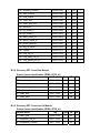
B.2 PET IMAGE IOD PRIVATE DATA ELEMENTS DEFINITION ............................................................152
B.2.1
Private Creator Identification Information .................................................................152
B.2.2
Discovery PET Patient Module .................................................................................152
B.2.3
Discovery PET Exam Module ...................................................................................152
B.2.4
Discovery PET Scan Module ....................................................................................152
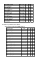
B.2.5
Discovery PET Frame Module..................................................................................155
B.2.6
Discovery PET ImageSet Module.............................................................................156
B.2.7
Discovery PET Image Module ..................................................................................158
B.2.8
Discovery PET Count Rate Module ..........................................................................159
B.2.9
Discovery PET Correction Cal Module .....................................................................159
B.2.10
Discovery PET Well Counter Module .......................................................................160
B.2.11
Discovery PET Raw Data Module ............................................................................161
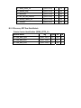
C.1 BASIC DIRECTORY IOD DEFINITION .........................................................................................162
C.2 DIRECTORY INFORMATION MODULE .........................................................................................162
C.3 DIRECTORY RECORD SELECTION KEYS....................................................................................163
C.3.1
Patient Keys..............................................................................................................163
C.3.2
Study Keys................................................................................................................163
C.3.3
Series Keys...............................................................................................................163
C.3.4
Image Keys ...............................................................................................................164
D.1 GE PRIVATE PET RAW DATA INFORMATION OBJECT IMPLEMENTATION .....................................165
D.1.1
Discovery PET RAW Data Patient Entity Module.....................................................165
D.1.2
Discovery PET RAW Data Exam Module .................................................................165
D.1.3
Discovery PET RAW Data Scan Entity Modules ......................................................166
D.1.4
Discovery PET RAW Data Equipment Entity Modules .............................................166
D.1.5
Discovery PET RAW Data Frame Entity Modules....................................................166
D.1.6
General Modules.......................................................................................................167
D.1.6.1
SOP Common Module Attributes..............................................................................167
1 SECTION 1 – INTRODUCTION
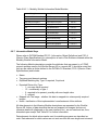
Note: Throughout this entire document the term “Discovery” refers to the following Discovery
products:
Discovery ST
Discovery RX
Discovery STE
1.1
Overview
Section 1, Introduction, provides general information about the content and scope of this
document.
Section 2, Network Conformance Statement, is the DICOM v3.0 Conformance Statement
related to this product Conformance Statements define the subset of options selected
from those offered by the DICOM v3.0 standard.
Section 3, Media Storage Conformance Statement, is the DICOM v3.0 Conformance
Statement related to Media Storage Application Profile.
Section 4, Print SCU Conformance Statement, is the DICOM v3.0 Conformance
Statement related to DICOM Print SCU Application. This product uses DICOM Print SCU
to print the images to DICOM Compliant Printers.
Section 5, DICOM Storage Commitment SCU, is the DICOM v3.0 Conformance
Statement related to DICOM Storage Commitment SCU Application. This product uses
DICOM Storage Commitment Push Model to store the images using remote DICOM
entity, which is Storage Commitment SCP.
Section 6, HIS/RIS (Modality Worklist) The ModalityWorklist option for Discovery allows a
user to query for and display DICOM modality worklist information. ModalityWorklist is
providing the DICOM C-FIND service as a service class user (SCU).
Section 7, Performed Procedure Step. The PPS option for Discovery, allows a Modality
Performed Procedure Step to be communicated to the Hospital/Radiology information
system. The PPS feature is providing the DICOM Modality Performed Procedure Step
service as a service class user (SCU).
Section 8, Gray Scale Presentation State. The Virtual Exam Split Option for Discovery
provides the DICOM Modality GSPS service as a service class user (SCU).
Appendix A specifies the CT/MR IOD information object.
Appendix B specifies the private data element definition for CT/PET/MR IOD.
Appendix C specifies the DICOMDIR directory information.
Appendix D specifies IOD Definitions for GE Private PET RAW Data IOD
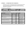
1.2
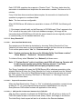
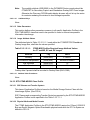
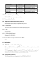
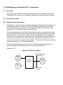
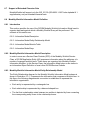
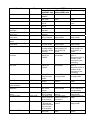
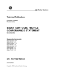
Overall Conformance Statement Documentation Structure
The documentation structure of the ID/Net v3.0 Conformance Statements and their
relationship with the DICOM v3.0 Conformance Statements is shown in Illustration 1-1.
Illustration 1-1
ID/Net v3.0
Introduction to the
Integrated
DICOM/Network
v3.0 (ID/Net v3.0)
Conformance
Statement
Direction:
5116427100
APPLICATION ENTITY SPECIFICATION
(SERVICE CLASSES, INFORMATION OBJECTS, MESSAGE EXCHANGES, ETC.)
Product
Implementation:
CT Advantage
Conformance
MR Advantage
Statement
Conformance
Direction:
Discovery
Statement
Conformance
Direction:
Statement
Direction:
5161694-100
......
Conformance
Statement
Direction:
......
DICOM STANDARD
Standard
Specification:
DICOM V 3.0
Part 1
DICOM V 3.0
Part 2
DICOM V 3.0
Part 3
DICOM V 3.0
Part 4
DICOM V 3.0
Part 13
The Documentation structure given in Illustration 1-1 shows the overall documentation
structure for all of the GE ID/Net v3.0 Conformance Statements.
This document specifies the DICOM v3.0 implementation supported by the Discovery. It is
entitled:
Discovery Conformance Statement for DICOM v3.0 (ID/Net v3.0), Direction
5161694-100.
This Conformance Statement documents the DICOM v3.0 Conformance Statement and
Technical Specification required to interoperate with the GE ID/Net v3.0 network interface.
Introductory information, which is applicable to all GE ID/Net v3.0 Conformance
Statements, is described in the document:
Introduction to the Integrated DICOM/Network v3.0 (ID/Net v3.0) Conformance
Statements, Direction 2118780
This introduction familiarizes the reader with DICOM terminology and general concepts. It
should be read prior to reading individual products’ ID/Net v3.0 Conformance Statements.
The ID/Net v3.0 Conformance Statement, contained in this document, also specifies the
Lower Layer communications that it supports (e.g. TCP/IP). However, the Technical
Specifications are defined in the DICOM v3.0 Part 8 standard.
For more information including Network Architecture and basic DICOM concepts, please
refer to the Introduction.
For the convenience of developers, there is a “collector” Direction available. By ordering
the collector, the Introduction described above and all of the currently published ID/Net
v3.0 Product Conformance Statements will be received. The collector Direction is:
ID/Net v3.0 Conformance Statements, Direction 2117016
For more information regarding DICOM v3.0, copies of the Standard may be obtained by
written request by contacting:
ACR-NEMA Representative
NEMA
1300 N. 17th Street, Suite 1847
Rosslyn, VA 22209 USA
1.3
Intended Audience
The reader of this document is concerned with software design and/or system integration
issues. It is assumed that the reader of this document is familiar with the DICOM v3.0
standards and with the terminology and concepts that are used in those standards.
If readers are unfamiliar with DICOM v3.0 terminology they should first refer to the
document listed below, then read the DICOM v3.0 Standard itself, prior to reading this
Conformance Statement document.
Introduction to the Integrated DICOM/Network v3.0 (ID/Net v3.0)
Conformance Statements
Direction 2118780
1.4
Scope and Field of Application
It is the intent of this document, in conjunction with the Introduction to the Integrated
DICOM/Network v3.0 (ID/Net v3.0) Conformance Statements Direction 2118780, to
provide an unambiguous specification for GE ID/Net v3.0 implementations. This
specification, called a Conformance Statement, includes a DICOM v3.0 Conformance
Statement and is necessary to insure proper processing and interpretation of GE medical
image data exchanged using DICOM v3.0. The GE ID/Net v3.0 Conformance Statements
are available to the public.
The reader of this conformance statement should be aware that different GE devices are
capable of using different Information Object Definitions. For example, a GE CT scanner
may send images using the CT Information Object, MR Information Object, Secondary
Capture Object, etc.
Included in this Conformance Statement are Module Definitions that define all data
elements used by the GE ID/Net v3.0 implementation. If the user encounters unspecified
private data elements while parsing a GE Data Set, the user is well advised to ignore
those data elements (per the DICOM v3.0 standard). Unspecified private data element
information is subject to change without notice. If, however, the device is acting as a “full
fidelity storage device”, it should retain and retransmit all of the private data elements that
are sent by GE devices.
1.5
Important Remarks
The use of these Conformance Statements, in conjunction with the DICOM v3.0
Standards, is intended to facilitate communication with GE imaging equipment. However,
by itself, it is not sufficient to insure that inter-operation will be successful. The
user (or user’s agent) needs to proceed with caution and address at least four issues:
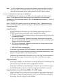
•
Integration
The integration of any device into an overall system of interconnected devices
goes beyond the scope of standards (DICOM v3.0), and of this introduction and
associated Conformance Statements when interoperability with non-GE equipment
is desired. The responsibility to analyze the applications requirements and to
design a solution that integrates GE imaging equipment with non-GE systems is
the user’s responsibility and should not be underestimated. The user is strongly
advised to ensure that such integration analysis is correctly performed.
•
Validation
Testing the complete range of possible interactions between any GE device and
non-GE devices, before the connection is declared operational, should not be
overlooked. Therefore, the user should ensure that any non-GE provider accepts
full responsibility for all validation required for their connection with GE devices.
This includes the accuracy of the image data once it has crossed the interface
between the GE imaging equipment and the non-GE device and the stability of the
image data for the intended applications.
Such a validation is required before any clinical use (diagnosis and/or treatment) is
performed. It applies when images acquired on GE imaging equipment are
processed/displayed on a non-GE device, as well as when images acquired on
non-GE equipment is processed/displayed on a GE console or workstation.
•
Future Evolution
GE understands that the DICOM Standard will evolve to meet the user’s growing
requirements. GE is actively involved in the development of the DICOM v3.0
Standard. DICOM v3.0 will incorporate new features and technologies and GE may
follow the evolution of the Standard. ID/Net v3.0 is based on DICOM v3.0 as
specified in each ID/Net DICOM Conformance Statement. Evolution of the
Standard may require changes to devices that have implemented DICOM v3.0. In
addition, GE reserves the right to discontinue or make changes to the support of
communications features (on its products) reflected on by these ID/Net DICOM
Conformance Statements. The user should ensure that any non-GE provider,
which connects with GE devices, also plans future evolution of the DICOM
standard. Failure to do so will likely result in the loss of function and/or connectivity
as the DICOM Standard changes and GE products are enhanced to support these
changes.
To be kept informed of the evolution of the implementation described in this
document, the user should register on the GE Internet server, accessible via
anonymous ftp, by entering his/her e-mail address (GE Internet Server Address:
ftp.med.ge.com: 192.88.230.11).
•
Interaction
It is the sole responsibility of the non-GE provider to ensure that communications
with the interfaced equipment does not cause degradation of GE imaging
equipment performance and/or function.
1.6
References
A list of references that are applicable to all ID/Net v3.0 Conformance Statements is
included in the Introduction to the Integrated DICOM/Network v3.0 (ID/Net v3.0)
Conformance Statements Direction 2118780.
1.7
Definitions
A set of definitions applicable to all ID/Net v3.0 Conformance Statements is included in
the Introduction to the Integrated DICOM/Network v3.0 (ID/Net v3.0) Conformance
Statements Direction 2118780.
1.8
Symbols and Abbreviations
A list of symbols and abbreviations that are applicable to all ID/Net v3.0 Conformance
Statements is included in the Introduction to the Integrated DICOM/Network v3.0 (ID/Net
v3.0) Conformance Statements Direction 2118780.
2 SECTION 2 – NETWORK CONFORMANCE STATEMENT
2.1
Introduction
This Conformance Statement (CS) specifies the Discovery compliance to DICOM v3.0. It
details the DICOM Service Classes and roles that are supported by this product in its
version 1.0.
The Discovery product uses DICOM services to import images for possible further
analysis and/or processing. It also uses DICOM services to export images to other
DICOM-compliant machines.
User has the capability to create and display Secondary Capture images, and transfer
Secondary Capture images via DICOM. The Secondary Capture option allows the user to
capture and store, in DICOM format, the presentation state of images as they are
displayed on the Image Display viewer. This provides the user with a digital alternative to
hardcopy filming: important portions of the study can be captured and stored on a PACS
or analysis workstation rather than captured on film.
The ability to Receive DICOM CT/MR images onto the Discovery scanner allows users to
co-register and fuse the anatomical detail of the CT/MR images with the Functional PET
images – through offline registration. The PET/CT images produced by Discovery are
perfectly aligned and fusion registration will be seamless.
The Discovery DICOM implementation allows the user to send CT/MR/PET Images,
Secondary Capture image data through the acquisition system or received from any other
DICOM Compliant system to another DICOM station. Discovery also allows query and
retrieve of data stored in its local database from a remote station and can query and
retrieve images stored in a remote DICOM station. In this situation Discovery is providing
the DICOM C-FIND and C-MOVE services as a service class provider (SCP) and that of a
DICOM C-FIND and C-MOVE service class user (SCU).
Connect Pro option provides additional capabilities Modality Worklist (MWL) and
Performed Procedure Step (MPPS), which provide integration of this GEMS imaging
equipment with Hospital Information System.
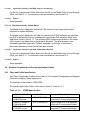
Note the format of this section follows the format of the DICOM Standard Part 2
(conformance) Annex A hence the paragraph numbering scheme. Please refer to that part
of the standard while reading this section.
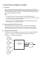
2.2
Implementation Model
All DICOM functionality on the Discovery product is handled by the DICOM Server
Application Entity (AE). The DICOM Server AE is commanded to perform DICOM
services through the buttons and menu selections on the main user interface panel. The
DICOM Server AE is also listening to a pre-defined port for incoming connections.
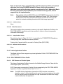
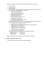
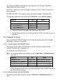
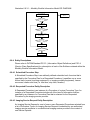
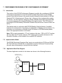
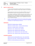
2.2.1 Application Data Flow Diagram
DICOM
Standard
ILLUSTRATION 2-0
IMPLEMENTATION MODEL DATA FLOW DIAGRAM
Choose
Push
Option
Image
Remotely
Stored
Image
Stored
locally
Remote system
requests image
storage
Query
Remote Q/R
SCP
Choose
Query
Remote
Option
Retrieve from
remote Q/R
SCP
Choose
Get Option
DICOM SERVER
AE
Query
Retrieve
SCP
Choose
ping
DICOM
Remote
Query/Get
Request
Verify
Request
host
Choose
archive
SAVE
Image Remotely
stored and
committed
There are five Real-World Activities that will cause the DICOM Server Application Entity
(DICOM Server AE) to initiate a DICOM association to a remote DICOM Application
Entity.
(1) The Choose “Push” Option Real-World activity consists of an operator selecting one or
more study, series or image in the local database manager and choosing either “Push
Examination”, “Push Series” or “Push Image from the “Network” pull-down menu on the
local database manager to send the image(s) to a selected destination.
(2) Real-World Activity, Query Remote, causes the DICOM Server AE to initiate an
association to the Remote DICOM AE and request the list of all studies. Once the DICOM
Server AE receives the list of studies, it will select the first study (as determined through
the local database manager list sort criterion) and request the list of series for that study.
After receiving the list of series the DICOM Server AE will ask for the list of images for the
first series in the list. The operator can then select any study in the study list to retrieve
the list of series and images.
(3) Real-World Activity, Choose “Get” Option, will be available once the Query Remote
activity is performed. The operator can now select one or more study (series or image)
and ask the DICOM Server AE to retrieve the selected image(s) from the Remote DICOM
AE by choosing “Get Examination”, “Get Series”, or “Get Images”.
(4) Real-World Activity, Choose “Ping DICOM host” Option, consists of an operator
selecting “Ping DICOM host” from the “Network” pull down menu. This will cause the
DICOM Server AE to initiate a “DICOM Verification Request” to the remote AE, to verify
the remote system activeness.
(5) The Choose “storage commitment” Option Real-World activity consists of an operator
configuring the remote node as an “archive node.” Select “choose media” option under
“Archive” pull down menu. Select “Remote Node” in that menu. Select one or more study,
series or image in the local database manager and choose either “Save Exam” or “Save
Series” from the “Archive” pull down menu. This will cause the DICOM server AE to send
the image(s) to the selected destination and wait for the storage commitment from the
remote node. The remote node should be a storage commitment provider.
There is no Real-World activity required for the DICOM Server AE to respond to an
incoming DICOM store, query or retrieve. The DICOM Server AE is always prepared to
respond to a DICOM Store, Query, or Retrieve by any remote DICOM AE.
The DICOM Server AE will perform the Real-World activity Image Installation after the
remote AE sends an image to the Discovery product.
Once a Query request is received, the DICOM Server AE will search the local database
for all entries that match the keys requested by the Remote DICOM AE and send back
the list of matches. The DICOM Server AE will also respond to an incoming retrieval
request from a Remote AE by sending the image(s) to the Destination AE.
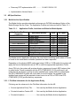
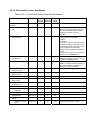
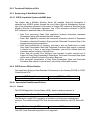
2.2.2 Functional Definition of AE’s
DICOM Server Application Entity initiates the following operations:
•
Ping DICOM Host (Verification): The DICOM Server initiates an association and sends
a C-ECHO-RQ message to the remote DICOM AE; the remote DICOM Server will
send back a C-ECHO-RSP message with a status of “success”.
•
Push: Initiate an association to a Remote AE to send image(s). If the Remote AE
accepts the presentation context applicable to the image(s) being sent, the DICOM
Server AE will send the image(s) by invoking C-STORE-RQ operation for each image
on the same association.
•
Query: Initiate an association with a Remote AE to query for images on the remote
host. A Study-Root Study-Level C-FIND-RQ request will be sent to the Remote AE
once an association has been established. After all responses are received, DICOM
Server AE will issue a Series-Level C-FIND-RQ request to get the series for a study in
the list. An Image-Level C-FIND-RQ will be issued for the first series in the series list.
•
Get: Send a C-MOVE-RQ request to a Remote AE after successful association
establishment. The DICOM Server AE’s Storage SCP will receive the images over a
separate association.
The DICOM Server AE waits for association requests from Remote AEs that wish to
perform the following operations:
•
Verification: If a C-ECHO-RQ message is received, the DICOM Server AE will send
back a C-ECHO-RSP message with a status of “success”.
•
Image Storage: If a C-STORE-RQ message is received, the DICOM Server AE will
receive the image and try to update the local database. If the image is stored
successfully on storage media and the database updated a status of “success” will be
returned in a C-STORE-RSP message.
•
Query: If a C-FIND-RQ message is received the DICOM Server AE will search the
database for the requested attributes and send back a C-FIND-RSP message
containing a match and a status of “pending”. After all matching records have been
sent, a status of “success’ will be returned in a C-FIND-RSP message. The Remote
AE can terminate the query by sending a C-CANCEL-FIND-RQ message.
•
Retrieve: If a C-MOVE-RQ message is received the DICOM Server AE will lookup its
list of configured Remote AEs for the Destination AE. If the Destination AE is
configured, the DICOM Server AE will open a new association to the Destination AE
and use C-STORE-RQ to send the image(s). The DICOM Server AE will send a CMOVE-RSP message with a status of “pending” after every five images are sent.
When all images are sent or if DICOM Server AE receives a C-CANCEL-MOVE-RQ a
final C-STORE-RSP will be sent back with an appropriate status.
2.2.3 Sequencing of Real-World Activities
Real-World Activity Query Remote must be performed before Choose Get Option can be
performed.
2.3
AE Specifications
2.3.1 DICOM Server AE Specification
This Application Entity provides Standard Conformance to the following DICOM v3.0 SOP
Classes as an SCU:
SOP Class Name (SCU)
Verification (Echo)
CT Image Information Storage
PET Image Storage
GE Private PET Raw data storage
MR Image Information Storage
Secondary Capture Image Storage
Study Root Query/Retrieve – FIND
Study Root Query/Retrieve – MOVE
SOP Class UID
1.2.840.10008.1.1
1.2.840.10008.5.1.4.1.1.2
1.2.840.10008.5.1.4.1.1.128
1.2.840.113619.4.30
1.2.840.10008.5.1.4.1.1.4
1.2.840.10008.5.1.4.1.1.7
1.2.840.10008.5.1.4.1.2.2.1
1.2.840.10008.5.1.4.1.2.2.2
Storage Commitment Push Model
1.2.840.10008.1.20.1
This Application Entity provides Standard Conformance to the following DICOM v3.0 SOP
classes as an SCP:
SOP Class Name (SCP)
Verification (Echo)
CT Information Storage
PET Image Storage
GE Private PET Raw data storage
MR Information Storage
Secondary Capture Image Storage
Study Root Query/Retrieve – FIND
Study Root Query/Retrieve – MOVE
SOP Class UID
1.2.840.10008.1.1
1.2.840.10008.5.1.4.1.1.2
1.2.840.10008.5.1.4.1.1.128
1.2.840.113619.4.30
1.2.840.10008.5.1.4.1.1.4
1.2.840.10008.5.1.4.1.1.7
1.2.840.10008.5.1.4.1.2.2.1
1.2.840.10008.5.1.4.1.2.2.2
2.3.1.1 Association Establishment Policy
2.3.1.1.1 General
The DICOM Application Context Name (ACN), which is always proposed, is:
Application Context Name
1.2.840.10008.3.1.1.1
The Maximum Length PDU negotiation is included in all association establishment
requests. The maximum length PDU for association initiated by the DICOM Server AE is:
Maximum Length PDU
51 Kbytes
SOP class Extended Negotiation is not supported.
Maximum PDU Length of Zero (0) is not supported. The association request will be
rejected when a request with “Maximum PDU length of zero” is received.
The maximum number of Presentation Context Items that is supported is 60. Note that the
same Abstract Syntax may be offered multiple times with different Transfer Syntax.
The user information items sent by this product are:
•
Maximum PDU Length and,
•
Implementation UID
2.3.1.1.2 Number of Associations
The DICOM Server AE (SCU) will initiate only one DICOM association at a time to
perform an image store to a remote host or retrieve image(s) from a Remote AE.
The DICOM Server AE (SCP) can have a maximum of four DICOM associations open
simultaneously to receive and store image store or respond to an echo.
2.3.1.1.3 Asynchronous Nature
Asynchronous mode is not supported. All operations will be performed synchronously.
2.3.1.1.4 Implementation Identifying Information
The Implementation UID allows unique identification of a set of products that share the
same implementation.
The Implementation UID for this ID/Net v3.0 Implementation is:
Discovery CT Implementation UID
Discovery PET Implementation UID
1.2.840.113619.6.55
1.2.840.113619.6.131
Note: CT AE and PET AE are the two different entities generating images.
2.3.1.2 Association Initiation by Real-World Activity
This AE attempts to initiate a new association due to a “ Ping DICOM Host” or “Push”
operation initiated by the user. A new association is also initiated when the user performs
a “Query Remote” operation or issues a retrieve operation by performing a “Get”
operation at Study/Series/Image level.
2.3.1.2.1 Push Image(s) to Remote AE
2.3.1.2.1.1
Associated Real-World Activity
The operator must first select a destination by choosing “Select Remote Host” from the
“Network” pull-down menu on the local database manager and then choose a hostname.
The “Push” operation will cause the DICOM server AE to initiate an Association when the
operator selects one or more study, series, or images in the local database manager and
then chooses either “Push Examination”, “Push Series”, or “Push Image” from the
“Network” pull-down menu on the local database manager.
Note: If multiple study, series, or images are chosen to be pushed, one association will
be established for each of the studies, series, or images.
2.3.1.2.1.2
Proposed Presentation Contexts
The following table shows the proposed presentation contexts for the DICOM Server AE
after Real-World Activity “Push” Operation has been performed.
Table 2.2.1.2.1.2-1
Proposed Presentation Contexts for DICOM Server AE and RealWorld activities Push, Query, Pull (Get Images) and Verification
(Dicom Ping) SCUs
Presentation Context Table – Proposal
Abstract Syntax
Name
CT Image Storage
UID
1.2.840.10008.5.1.4.1.1.2
Transfer Syntax
Name List
Explicit VR Little Endian
Explicit VR Big Endian
Implicit VR Little Endian
Role
Extended
Negotiation
SCU
None
UID List
1.2.840.10008.1.2.1
1.2.840.10008.1.2.2
1.2.840.10008.1.2
Presentation Context Table – Proposal
Abstract Syntax
Name
PET Image
Storage
GE Private PET
Raw data SOP
class
MR Image Storage
UID
Name List
Role
Extended
Negotiation
SCU
None
SCU
None
SCU
None
UID List
Implicit VR Big Endian (GE
Private)
Explicit VR Little Endian
1.2.840.113619.5.2
Explicit VR Big Endian
1.2.840.10008.1.2.2
Implicit VR Little Endian
Explicit VR Little Endian
1.2.840.10008.1.2
1.2.840.10008.1.2.1
Explicit VR Big Endian
1.2.840.10008.1.2.2
Implicit VR Little Endian
Explicit VR Little Endian
Explicit VR Big Endian
Implicit VR Little Endian
Implicit VR Big Endian (GE
Private)
Explicit VR Little Endian
Explicit VR Big Endian
Implicit VR Little Endian
Implicit VR Big Endian (GE
Private)
Implicit VR Little Endian
1.2.840.10008.1.2
1.2.840.10008.1.2.1
1.2.840.10008.1.2.2
1.2.840.10008.1.2
1.2.840.113619.5.2
1.2.840.10008.1.2.1
1.2.840.10008.1.2.2
1.2.840.10008.1.2
1.2.840.113619.5.2
SCU
None
1.2.840.10008.1.2
SCU
None
1.2.840.10008.5.1.4.1.2.2.
2
Implicit VR Little Endian
1.2.840.10008.1.2
SCU
None
1.2.840.10008.1.1
Implicit VR Little Endian
1.2.840.10008.1.2
SCU
None
1.2.840.10008.5.1.4.1.1.12
8
1.2.840.113619.4.30
1.2.840.10008.5.1.4.1.1.4
1.2.840.10008.5.1.4.1.1.7
Secondary Capture
Image Storage
Study Root
Query/Retrieve
FIND
Study Root
Query/Retrieve
MOVE
Verification SOP
Class
Transfer Syntax
1.2.840.10008.5.1.4.1.2.2.
1
1.2.840.10008.1.2.1
Note: Other Abstract Syntax and Transfer Syntax names may be offered when
establishing an association. These are private syntax that may be ignored. See
section 2.4.
2.3.1.2.1.2.1 SOP Specific Conformance Statement C_STORE SCU
This implementation can perform multiple C-STORE operations over a single association.
Upon receiving a C-STORE confirmation containing a successful status, this
implementation will perform the next C-STORE operation. The association will be
maintained if possible.
Upon receiving a C-STORE confirmation containing a Refused status, this implementation
will terminate the association.
Upon receiving a C-STORE confirmation containing any status that is not Success or
Refused, this implementation will consider the current request to be a failure but will
continue to attempt to send the remaining images in the request on the same association.
Each C-STORE operation supports an “Association Timer”. This timer starts when the
association request is sent or received and stops when the association is established.
The time-out is 900 seconds.
Each C-STORE operation also supports an “Operation Inactivity Timer”. This time-out
starts once the first C-STORE request has been issued (on association) or received and
is reset each time a C-STORE response has been received or when subsequent CSTORES are sent. This time-out is 900 seconds.
Each C-STORE operation also supports a “Session Timer”. This timer starts when the
association is established and stops when the association is ended. This time-out is 60
minutes.
If any of the three timers mentioned above expires, the connection is closed and the
operation in progress is considered failed.
Note: The time-outs are configurable.
When DICOM Server AE initiates an association to issue a C-STORE, the following will
occur:
1. If the image is stored locally on the Discovery in DICOM format (“Dicm” appears in the
“Fmt” column at the exam level of the local database manager), the image will be
transmitted by the DICOM Server AE with the same elements as was originally received
or created locally (for the standard elements only).
2.3.1.2.2 Query Remote AE
2.3.1.2.2.1
Associated Real-World Activity
The operator must first select a destination by choosing “Select Remote Host” from
“Network” pull-down menu on the local database manager and then choose a hostname.
To do custom queries select “Yes” for “Custom search” option.
Note: Custom queries can be done on the following fields “Last Name contains”,
“Exam Number”, “Patient Id”, “Accession Number”.
To initiate a Query select “Receive” from “Network” pull-down menu.
Note: If “Custom Search” option is set then a small GUI will show up. Operator will
be able to enter custom query fields. Entering values in ”Last Name
contains” field will initiate wild card query for patient name.
The “Query” operation will cause the DICOM Server AE to initiate an association to the
selected Remote AE when the “Query Remote Host” entry is selected from the “Network”
pull-down menu. Once a list of Study/Series/Image is retrieved, the operator can invoke
the “Get” operation by choosing “Get Exam” or “Get Series” or “Get Image” from the
“Network” pull-down menu.
2.3.1.2.2.2
Proposed Presentation Contexts
When the Real-World activity “Query” or “Get” is initiated all presentation contexts shown
in table 2.2.1.2.1.2-1 are proposed during association establishment, but only the
Query/Retrieve-FIND related contexts are applicable to this activity.
2.3.1.2.2.2.1 SOP Specific Conformance Statement for C-FIND SCU
After the Query operation is initiated, the DICOM Server AE will perform a study-root CFIND-RQ request at each of the three levels (Study, Series, and Image) in succession.
The Initial Study-Level request will ask for all studies in the Remote database.
The C-FIND SCU will not perform any extended negotiation and so will only perform
hierarchical query. Relational Queries are not supported.
Each C-FIND SCU operation supports an “Association Timer”, “Operation Inactivity Timer”
and “Session Timer” with time out values of 900 seconds, 900 seconds and 60 minutes
respectively.
If a “Cancel” or “Refused” status is returned from the Remote AE the association is closed
and the operation terminated.
The DICOM Server AE will parse each matching C-FIND-RSP reply and ignore the
entries it fails to parse. Tables 2.2.1.2.2.2.1-1 - 2.2.1.2.2.2.1-3 shows the various fields
that are requested at the Study, Series, and Image levels of the C-FIND request.
Query results are filtered based on the Modality field. Only CT/MR/PET Screen Save
images are supported.
Table 2.2.1.2.2.2.1-1: Requested Study Level Keys
Description
Type
Tag
Value
Study date
Study time
Patient’s name
Study id
Study Instance UID
Study description
Private Creator Identification
Suite Id
R
R
R
R
U
O
P1
P2
0008,0020
0008,0030
0010,0010
0020,0010
0020,000D
0008,1030
0009,00xx
0009,xx02
Zero length
Zero length
Zero length
Zero length
Zero length
Zero length
GEMS_IDEN_01
Zero Length
Table 2.2.1.2.2.2.1-2: Requested Series Level Keys
Description
Type
Tag
Value
Modality
Series number
Series Instance UID
Series description
Manufacturer
Images in series
R
R
U
O
O
O
0008,0060
0020,0011
0020,000E
0008,103E
0008,0070
0020,1002
Zero length
Zero length
Series UID
Zero length
Zero length
Zero length
Table 2.2.1.2.2.2.1-3: Requested Image Level Keys
Description
Type
Tag
Value
Image number
Image Instance UID
Image type
R
U
O
0020,0013
0008,0018
0008,0008
Zero length
Image UID
Zero length
1 Private data element
Description
Type
Tag
Value
Rows
Columns
Image position
Image orientation
Slice thickness
Slice spacing
Gantry tilt
Convolution kernel
Reconstruction diameter
Data collection diameter
Flip angle
Echo number
Echo time
Inversion time
Repetition time
Private Creator Identification
Dfov Rect
Dfov Rect
Midscan Time
Azimuth
Number of Echo
Private Creator Identification
Scout Anref
Private Creator Identification
Location RAS
Location
Center R Coordinate
Center A Coordinate
Table Start Location
Table End Location
RAS Letter for Side of Image
RAS Letter for Anterior/Posterior
RAS Letter for Scout Start Location
RAS Letter for Scout End Location
Image Dimension X
Image Dimension Y
O
O
O
O
O
O
O
O
O
O
O
O
O
O
O
P
P
P
P
P
P
P
P
P
P
P
P
P
P
P
P
P
P
P
P
P
0028,0010
0028,0011
0020,0032
0020,0037
0018,0050
0018,0088
0018,1120
0018,1210
0018,1100
0018,0090
0018,1314
0018,0086
0018,0081
0018,0082
0018,0080
0019,00xx
0019,001E
0019,xx1E
0019,xx24
0019,xx26
0019,xx7E
0021,00xx
0021,xx4A
0027,00xx
0027,xx40
0027,xx41
0027,xx42
0027,xx43
0027,xx50
0027,xx51
0027,xx52
0027,xx53
0027,xx54
0027,xx55
0027,xx60
0027,xx61
Zero length
Zero length
Zero length
Zero length
Zero length
Zero length
Zero length
Zero length
Zero length
Zero length
Zero length
Zero length
Zero length
Zero length
Zero length
GEMS_ACQU_01
Zero Length
Zero Length
Zero Length
Zero Length
Zero Length
GEMS_RELA_01
Zero Length
GEMS_IMAG_01
Zero Length
Zero Length
Zero Length
Zero Length
Zero Length
Zero Length
Zero Length
Zero Length
Zero Length
Zero Length
Zero Length
Zero Length
Note: Refer to section 2.3.1.2.2.1 for Custom Search/Query option.
2.3.1.2.3 Get Image(s) from Remote AE
2.3.1.2.3.1
Associated Real-World Activity
The operator must first select a destination by choosing “Select Remote Host” from
“Network” pull-down menu on the local database manager and then choose a hostname.
The operator then has to perform the Real-World activity “Query” to get a list of
Study/Series/Image. Once the list of Study/Series/Image is retrieved, the operator can
invoke the “Get” operation by choosing “Get Exam” or “Get Series” or “Get Image” from
the “Network” pull-down menu.
2.3.1.2.3.2
Proposed Presentation Contexts
When the Real-World activity “Get” is initiated all presentation contexts shown in table
2.2.1.2.1.2-1 are proposed during association establishment, but only the Query/RetrieveMOVE related contexts are applicable to this activity.
2.3.1.2.3.2.1 SOP Specific Conformance Statement for C-MOVE SCU
When the operator starts a Get operation at any level (Study, Series, Image) the DICOM
Server AE will initiate a C-MOVE-RQ request to the Remote AE with the DICOM Server
AE as the Destination AE. The Storage SCP will handle the incoming images as
described in section 2.2.1.3.1.
Each C-MOVE SCU operation supports an “Association Timer”, “Operation Inactivity
Timer” and “Session Timer” with time out values of 900 seconds, 300 seconds and 60
minutes respectively.
The DICOM Server AE will send a C-CANCEL-MOVE-RQ to the Remote AE if the
operator “Pauses” or “Clears” the job from the local database manager Network queue.
2.3.1.2.4 Real-World Activity: Verify (DICOM Ping)
2.3.1.2.4.1
Associated Real-World Activity
The operator must first select a destination by choosing “Select Remote Host” from
“Network” pull-down menu on the local database manager and then choose a hostname.
The operator must then select the “Ping DICOM host” form “Network” pull-down menu.
The DICOM server will initiate an association with the remote DICOM AE in order to verify
communication at the application level. The success or failure of the verification process
is displayed to the user.
2.3.1.2.4.2
Proposed Presentation Context Table
Refer to the Table 2.2.1.2.1.2-1 for the Proposed Presentation Contexts for DICOM
Server AE and Real-World activity Verification
2.3.1.2.4.2.1 SOP Specific DICOM Conformance C_ECHO SCU
The Discovery DICOM Server AE provides standard conformance to the DICOM
Verification Service Class.
Each ECHO operation supports an “Association Timer”, “Operation Inactivity Timer” and
“Session Timer” with time out values of 900 seconds, 30 seconds and 60 minutes
respectively
2.3.1.2.5 Real-World Activity: Storage Commitment
2.3.1.2.5.1
Associated Real-World Activity
The operator must first select a destination by choosing “Select Remote Host” from
“Network” pull-down menu on the local database manager and then choose a hostname.
Select the “Update” option, if the hostname is already present. Set the “Archive Node”
option to “Yes”. If the remote host is not present add the remote host in the local database
with “Archive Node” option set to “Yes”.
Note: The remote node should be a Storage Commitment SCP.
The operator must then select “ Archive “ pull-down menu on the local database manager.
Select “Select Media” option menu. Select “Remote Node” in the menu.
Note: Only if you configure the remote node as a “archive node” will you see the
remote node option in the archive menu.
The operator then selects one or more study, series, or images in the local database
manager and then chooses “Save Examination”, “Save Series”, or “Save Image” from the
“Archive” pull-down menu on the local database manager.
Note: Also refer to section 5.3.1.3
2.3.1.2.5.2
Proposed Presentation Context Table
Refer to section 5.3.1.4
2.3.1.2.5.3
SOP Specific Conformance Statement Storage Commitment SCU
Refer to section 5.3.1.4
2.3.1.3 Association Acceptance Policy
The DICOM Server AE places limitations on who may connect to it.
If the Remote AE needs to “Push Images” or “Query/Retrieve Images”, to the local system
then it has to be configured in the Local system to do the same.
To configure a remote AE choose “Select Remote Host” in the “network” pull down menu.
Select the Remote Host and choose “Update” option, if the Remote AE is already present.
If the Remote AE is not present choose “Add” option to add the Remote AE.
Set “Push Images” option to “Yes”, if the Remote AE needs to push images to the Local
system
Set “Query/Retrieve” option to “Yes”, if the Remote AE needs to “Query/Retrieve” the
local system.
When the DICOM Server AE accepts an association for image storage, it will receive any
images transmitted on that association and store the images on disk.
It will also respond to queries from Remote AEs by sending matching entries. Any
Remote AE can request and receive a list of images on the local database. The Remote
AE must be configured in the local database manager’s list of Remote AE for it to be able
to retrieve images from DICOM Server AE.
Any remote AE can open an association to the DICOM Server AE for the purpose of
verification.
2.3.1.3.1 Receive Image(s)
This AE is indefinitely listening for associations. No operator action is required to receive
an image.
2.3.1.3.1.1
Associated Real-World Activity
The Real-World Activity associated with the Receive Image(s) operation is the storage of
the image on the disk drive of the Discovery.
2.3.1.3.1.2
Presentation Context Table
Table 2.2.1.3.1.2-1:
Accepted Presentation Contexts for DICOM Server AE and RealWorld Activity Receive Image(s)
Presentation Context Table – Proposal
Abstract Syntax
Name
CT Image Storage
PET Image
Storage
GE Private PET
Raw data SOP
class
MR Image Storage
UID
1.2.840.10008.5.1.4.1.1.2
Name List
1.2.840.10008.1.2.1
1.2.840.10008.1.2.2
1.2.840.10008.1.2
1.2.840.113619.5.2
Explicit VR Big Endian
1.2.840.10008.1.2.2
Implicit VR Little Endian
Explicit VR Little Endian
1.2.840.10008.1.2
1.2.840.10008.1.2.1
Explicit VR Big Endian
1.2.840.10008.1.2.2
Implicit VR Little Endian
Explicit VR Little Endian
Explicit VR Big Endian
Implicit VR Little Endian
Implicit VR Big Endian (GE
Private)
Explicit VR Little Endian
Explicit VR Big Endian
Implicit VR Little Endian
Implicit VR Big Endian (GE
Private)
Implicit VR Little Endian
1.2.840.10008.1.2
1.2.840.10008.1.2.1
1.2.840.10008.1.2.2
1.2.840.10008.1.2
1.2.840.113619.5.2
1.2.840.10008.5.1.4.1.2.2.
2
1.2.840.10008.1.1
1.2.840.10008.5.1.4.1.1.12
8
1.2.840.113619.4.30
1.2.840.10008.5.1.4.1.1.4
1.2.840.10008.5.1.4.1.1.7
1.2.840.10008.5.1.4.1.2.2.
1
Role
Extended
Negotiation
SCU
None
UID List
Explicit VR Little Endian
Explicit VR Big Endian
Implicit VR Little Endian
Implicit VR Big Endian (GE
Private)
Explicit VR Little Endian
Secondary Capture
Image Storage
Study Root
Query/Retrieve
FIND
Study Root
Query/Retrieve
MOVE
Verification SOP
Class
Transfer Syntax
1.2.840.10008.1.2.1
SCU
None
SCU
None
SCU
None
1.2.840.10008.1.2.1
1.2.840.10008.1.2.2
1.2.840.10008.1.2
1.2.840.113619.5.2
SCU
None
1.2.840.10008.1.2
SCU
None
Implicit VR Little Endian
1.2.840.10008.1.2
SCU
None
Implicit VR Little Endian
1.2.840.10008.1.2
SCU
None
Note:
The SCP acceptance policy is the order of the transfer syntaxes specified in the above
table if more than one acceptable transfer syntax is proposed by the SCU and the first
match with the acceptable transfer syntax proposed by the SCU will be accepted.
2.3.1.3.1.2.1 SOP Specific Conformance to C_STORE SCP
The DICOM Server AE conforms to the SOP’s of the Storage Service Class at level 1
(base). Private elements will be discarded from the image when receiving images
containing non-GE private data elements. All of the standard type elements (1,1c,2,2c,3)
will be retained.
Each C-STORE SCP operation supports an “Association Timer”, “Operation Inactivity
Timer” and “Session Timer” with time out values of 900 seconds, 900 seconds and 60
minutes respectively.
Image Reception
If the DICOM Server AE returns one of the following status codes, then the CSTORE operation was unsuccessful and no image will be installed:
•
0110 (Processing Failure) Indicates that an internal system call has failed while
processing an image.
•
A711 (Out of Resources) Indicates that probably there was not enough disk
space to store the image. The user should attempt recovery by removing some
images from the Discovery system.
•
A712 (Out of Resources) Indicates that there was not enough resource (such
as memory) to store the image.
•
A800 (SOP Class not supported)
In the event of a successful C-STORE operation, the image has successfully been
written to disk. The image will then be accessed in the same manner as any other
image by the applications on the Discovery system.
Images may be deleted when instructed to do so by the user. Thus the duration of
the storage of the image is determined by the users of the Discovery system.
Image Installation
If the image installation is unsuccessful, a message will appear in the Message Log
informing the user of the failure and the image will be removed.
If the image installation process finds that an element is not encoded according to
the DICOM standard, it will fail to install the image and the file will be removed.
Image Installation of non-GE Created MR or CT or PET Images
Images received from non-GE products are installed as appropriate image object
without any of their private data elements. Also if some critical fields (mandatory)
are missing, then the image will not be installed.
2.3.1.3.2 Verification Request from Remote AE
This AE is indefinitely listening for associations. No operator action is required to respond
to a verification message.
2.3.1.3.2.1
Associated Real-World Activity
The Real-World Activity associated with the verification request is to send a C-ECHO
response message with a status of “success” to the requesting AE.
2.3.1.3.2.2
Presentation Context Table
Table 2.2.1.3.2.2-1: Acceptable Presentation Contexts for DICOM Server AE and
Real-World Activity Verification Request
Presentation Context Table
Abstract Syntax
Transfer Syntax
Name
UID
Name List
UID List
Verification
1.2.840.10008.1.1
Implicit VR Little Endian
1.2.840.10008.1.2
Role
Extended
Negotiation
SCP
None
2.3.1.3.2.2.1 SOP Specific Conformance to C_ECHO SCP
The DICOM Server AE provides standard conformance to the DICOM Verification Service
Class.
Each ECHO operation supports an “Association Timer”, “Operation Inactivity Timer” and
“Session Timer” with time out values of 900 seconds, 30 seconds and 60 minutes
respectively.
2.3.1.3.3 Query Request from Remote AE
This AE is indefinitely listening for associations. No operator action is required to respond
to a query request.
2.3.1.3.3.1
Associated Real-World Activity
The Real-World Activity associated with the query request is to search the local database
for entries that match the request and send a C-FIND response message with a status of
“pending” for each matching entry.
2.3.1.3.3.2
Presentation Context Table
Table 2.3.1.3.3.2-1: Acceptable Presentation Contexts for DICOM Server AE and RealWorld Activity Query Request
Presentation Context Table
Abstract Syntax
Transfer Syntax
Name
UID
Name List
UID List
Study Root
Query/Retrieve
FIND
1.2.840.10008.5.1.4.1.2.2.1
Implicit VR
Little Endian
1.2.840.10008.1.2
Role
Extended
Negotiation
SCP
None
2.3.1.3.3.2.1 SOP Specific Conformance to C-FIND SCP
Each C-FIND SCP operation supports an “Association Timer”, “Operation Inactivity Timer”
and “Session Timer” with time out values of 900 seconds, 900 seconds and 60 minutes
respectively.
All Required (R) and Unique (U) study, series, and image level keys for the Study-Root
Query/Retrieve information model are supported. Some optional (O) keys are also
supported as described in the following tables.
Table 2.3.1.3.3.2.1-1
Supported study level keys
Description
Study date
Study time
Accession number
Patient’s name
Patient id
Study id
Study Instance UID
Study description
Suite Id
Table 2.3.1.3.3.2.1-2
Tag
R
R
R
R
R
R
U
O
P
0008,0020
0008,0030
0008,0050
0010,0010
0010,0020
0020,0010
0020,000D
0008,1030
0009,0002
Usage
Matched
Matched
Matched
Matched
Matched
Matched
Matched
Returned
Returned
Supported series level keys
Description
Modality
Series number
Series Instance UID
Series description
Manufacturer
Images in series
Table 2.3.1.3.3.2.1-3
Type
Type
Tag
R
R
U
O
O
O
0008,0060
0020,0011
0020,000E
0008,103E
0008,0070
0020,1002
Usage
Matched
Matched
Matched
Returned
Returned
Returned
Supported image level keys
Description
Image number
Image Instance UID
Image type
Rows
Columns
Image position
Image orientation
Slice thickness
Slice spacing
Gantry tilt
Convolution kernel
Type
Tag
R
U
O
O
O
O
O
O
O
O
O
0020,0013
0008,0018
0008,0008
0028,0010
0028,0011
0020,0032
0020,0037
0018,0050
0018,0088
0018,1120
0018,1210
Usage
Matched
Matched
Returned
Returned
Returned
Returned
Returned
Returned
Returned
Returned
Returned
Description
Reconstruction diameter
Data collection diameter
Flip angle
Echo number
Echo time
Inversion time
Repetition time
Trigger time
Dfov Rect
Midscan Time
Azimuth
Number of Echo
Scout Anref
Location RAS
Location
Center R Coordinate
Center A Coordinate
Table Start Location
Table End Location
RAS Letter for Side of Image
RAS Letter for Anterior/Posterior
RAS Letter for Scout Start Location
RAS Letter for Scout End Location
Image Dimension X
Image Dimension Y
Type
Tag
O
O
O
O
O
O
O
O
P
P
P
P
P
P
P
P
P
P
P
P
P
P
P
P
P
0018,1100
0018,0090
0018,1314
0018,0086
0018,0081
0018,0082
0018,0080
0018,1060
0019,001E
0019,0024
0019,0026
0019,007E
0021,004A
0027,0040
0027,0041
0027,0042
0027,0043
0027,0050
0027,0051
0027,0052
0027,0053
0027,0054
0027,0055
0027,0060
0027,0061
Usage
Returned
Returned
Returned
Returned
Returned
Returned
Returned
Returned
Returned
Returned
Returned
Returned
Returned
Returned
Returned
Returned
Returned
Returned
Returned
Returned
Returned
Returned
Returned
Returned
Returned
Note: In the above tables the type field has the following meaning:
R = Required U = Unique O = Optional P = Private
Only keys with Usage type Matched will be matched against values in the database.
Values in keys of type Returned will be ignored and will be filled in with data from the
database.
If an optional key is requested that does not appear in any of the tables above, that key
will be ignored and no corresponding element will be returned.
If the database does not have a value corresponding to any requested optional key a
zero-length element will be returned.
Sequence matching is not supported.
Range matching is supported for attributes of type date and time.
Only hierarchical query is supported.
2.3.1.3.4 Retrieve Request From Remote AE
This AE is indefinitely listening for associations. No operator action is required to respond
to a retrieve request.
2.3.1.3.4.1
Associated Real-World Activity
The Real-World Activity associated with the Retrieve Request is to send all images
corresponding to the C-MOVE request to the destination AE through a separate
association.
2.3.1.3.4.2
Presentation Context Table
Table 2.3.1.3.4.2-1: Acceptable Presentation Contexts for DICOM Server AE and
Real-World Activity Retrieve Request.
Presentation Context Table
Abstract Syntax
Transfer Syntax
Name
UID
Name List
UID List
Study Root
Query/Retrieve
MOVE
1.2.840.10008.5.1.4.1.2.2.2
Implicit VR
Little Endian
1.2.840.10008.1.2
Role
Extended
Negotiation
SCP
None
2.3.1.3.4.2.1 SOP Specific Conformance to C-MOVE SCP
The DICOM Server AE provides standard conformance to the baseline Study-root CMOVE Service Class SCP.
Each C-MOVE SCP operation supports an “Association Timer”, “Operation Inactivity
Timer” and “Session Timer” with time out values of 900 seconds, 300 seconds and 60
minutes respectively. These time-outs are configurable in dcs.cfg as bi_assoc_tio,
bi_store_tio and bi_session_tio respectively
All images requested in a C-MOVE-RQ will be sent over a single association. A C-MOVERSP with a “pending” status will be returned to the requester every five images.
The C-MOVE SCP will invoke C-STORE requests for the following SOP classes:
SOP Class Name
SOP Class UID
CT Image Information Storage
1.2.840.10008.5.1.4.1.1.2
MR Image Information Storage
PET Image Storage
GE Private PET Raw data storage
1.2.840.10008.5.1.4.1.1.4
1.2.840.10008.5.1.4.1.1.128
1.2.840.113619.4.30
Secondary Capture image storage
1.2.840.10008.5.1.4.1.1.7
Standalone Overlay storage
1.2.840.10008.5.1.4.1.1.8
In addition to the C-MOVE response status values defined in DICOM V3.0 part 4 the
following status values will be returned:
•
C000
Indicates that an error occurred while retrieving records from the local
2.3.1.3.4.3
•
C001
•
C011
database.
Indicates all other processing error.
If the Destination AE returns a “Storage Full” condition this status will be
returned. This status will only be sent if the Destination AE returns a
status of A711 and is only applicable if the Destination AE is another
GE Medical Systems product.
Presentation Context Acceptance Criteria
No criterion.
2.3.1.3.4.4
Transfer Syntax Selection Policy
All protocols detailed above in the tables are supported; no priority selection is given.
2.4
Communication Profiles
2.4.1 Supported Communication Stacks (parts 8,9)
DICOM Upper Layer (Part 8) is supported using TCP/IP.
2.4.2 TCP/IP Stack
The TCP/IP stack is inherited from a UNIX Operating System.
2.4.2.1 Physical Media Support
Ethernet v2.0, IEEE 802.3. Auto senses 10/100 Base T Ethernet connection.
2.4.3 Point-to-Point Stack
A 50-pin ACR-NEMA connection is not applicable to this product.
2.5
Extensions / Specializations / Privatizations
2.5.1 Specialized Information Object Definition
Following is a list of additional private attributes defined for a standard CT IOD.
(0008,0008)
Value 3: CT Image IOD specific specializations
AXIAL
LOCALIZER
SEGMENTED
REFORMATTED
PROCESSED
COMBINED
Value 4: CT Image implementation specific
MIN IP
MIP
AVERAGE
VOLREN
INTEGRAL
HD MIP
RAYSUM
SURFACE
MINMAX
(0018,0022)
Scan Options: Defined Terms
AXIAL MODE
DYNAMIC MODE
SCOUT MODE
AXIAL MODE
STATIC XRON MODE
STATIC XROFF MODE
TUBE HEAT MODE
DAS MODE
TUBE CAL MODE
BIOPSY MODE
CINE
HELICAL
ROTGENCAL MODE
2.5.2 Private Data Elements
Refer to Appendix B for a complete listing of private data elements used with this
implementation.
2.6
Configuration
2.6.1 AE Title/Presentation Address Mapping
The Discovery system allows the user to “add”, “Remove”, or “Update the mapping of
remote AE Titles to IP Addresses and Ports. These options can be selected from the
“Remote Host Selection” menu displayed by choosing “Select Remote Host” from the
“Network” pull-down menu from the local database manager.
2.6.2 Configurable Parameters
The following fields are configurable for the DICOM Server AE:
•
•
•
•
•
Local AE Title (the machine hostname)
Local IP Address
Local IP Netmask
Max PDU length
Time-outs, which are set for all hosts, are configurable in dcs.cfg:
*Association time-out
- bi_assoc_tio
*Session timeout
- bi_session_tio
*Create timeout
2.7
- bi_ncreate_tio
Note:
All configurations should be performed by a GE Field Service Engineer.
Note:
The local port on which the Discovery system receives DICOM incoming TCP
connections is port 4006.
Support of Extended Character Sets
In addition to the DICOM default character set, Discovery supports the ISO_IR 100 Latin
alphabet #1 supplementary set for the purpose of interchange.
3 MEDIA STORAGE CONFORMANCE STATEMENT
3.1
Introduction
This conformance statement specifies the Discovery conformance to the DICOM V3.0
Media Interchange. It details the DICOM Media Storage Application Profiles and roles that
are supported by this product in its version 1.0. Discovery has a Media Archive Server,
which supports both MOD and DVD-RAM.
Note:
3.2
•
The format of this section follows the format of the DICOM Standard Part 2
(conformance) Annex A, hence the paragraph numbering scheme. Please refer to that
part of the standard while reading this section.
•
Media would refer to both MOD and DVD-RAM unless specified explicitly with the
actual media name viz., MOD or DVD-RAM.
Implementation Model: MOD Archive Server
All DICOM functionality on the Discovery product is handled by the DICOM Server
Application Entity (AE). The DICOM Server AE is commanded to perform DICOM
services through the buttons and menu selections on the main user interface panel.
3.2.1 Application Data Flow Diagram
The Media Archive Server creates and/or updates the media with various DICOM SOP
instances. It can process CT, MR, PET, Secondary Capture and Overlay IOD's.
Illustration 3-1:
Specific AE Application Model
Display
Directory
Create
Media
DICOM Media
Archive Server
AE
FSC
FSU
FSR
Local
Storage
Update
Media
Media
Storage
The Media Archive Server AE has a local storage that may contain various SOP
instances. These may have been obtained by original creation, network (DICOM or
proprietary) or by removable media using other application entities. These instances are
external to this conformance claim and the origin of SOP instances is outside the scope of
this claim.
The Media Archive Server AE can initialize Media by acting as an FSC to create a new
DICOM File-set on a media. It initializes the DICOM File-set and writes the specified SOP
instances onto the media. The SOP instances written will be limited to instances that
match the criteria of one of the Application Profiles that is supported. When updating
media, a pre-existing File-set will be updated with the selected SOP instances that match
one of the supported Application Profiles.
3.2.2 Functional Definitions of AE's
This Server has only one Application Entity: the Media Archive Application.
The Media Archive Application can perform these functions:
•
It can initialize (create DOS filesystem) a piece of media, writing a new label and
DICOM File-set onto the media. (“LABEL”)
•
It can update a piece of media by adding new SOP instances to an already existing
DICOM File-set from local storage. (“SAVE”)
•
It can display a directory listing of the File-set on a piece of media. (QUERY)
•
It can copy SOP instance from the Media onto local storage. (“RESTORE”)
3.2.3 Sequencing of Real World Activities
The updating function can only be performed on a piece of media that has already had a
DICOM File- set created.
The display function can only be performed on a piece of media that has already has a
DICOM File-set created. With no SOP instances having been added, the directory will be
displayed empty.
The copy function can only be performed with a piece of media that has been updated
and has DICOM SOP instances in the File-set.
There are no other sequencing requirements.
3.2.4 File Meta Information for Implementation Class and Version
The File Meta-Information for this implementation is:
•
File Meta-Information Version...................... 1
•
Discovery CT Implementation UID............... 1.2.840.113619.6.55
3.3
•
Discovery PET Implementation UID ............ 1.2.840.113619.6.131
•
Implementation Version Name .................... 1.0
AE Specifications
3.3.1 Media Archive Specification
The Media Archive provides standard conformance to DICOM Interchange Option of the
Media Storage Service Class. The Application Profiles and roles are listed in Table 3.1-1.
Table 3.1-1:
Application Profile, Activities and Roles for Media Update
Application Profiles
Supported
STD-CTMR-MOD23
STD-CTMR-MOD12
PRI-CTMR-MOD12
Real World Activity
Create Media
Update Media
Display Directory
Copy To Local Storage
Create Media
Update Media
Display Directory
Copy To Local Storage
Update Media
Display Directory
Copy To Local Storage
Role
SC Option
FSC
FSU
FSR
FSR
FSC
FSU
FSR
FSR
FSU
FSR
FSR
Interchange
Interchange
Interchange
Interchange
Interchange
Interchange
Interchange
Interchange
Interchange
Interchange
Interchange
The Media Archive Application will query the user before initializing media when a File-set
is found on the media and an initialize operation has been requested.
Depending on the physical MOD media type being 2.3GB or 1.2GB media, the system will
apply the correct characteristics as an FSC to meet the appropriate Application Profile.
As an FSU role, the system will produce directory sequences for each SOP instance that
is added to the File-set consistent with the STD-CTMR-MOD {12,23} profile and it will
make the File-set directory so that an early installed base system that only understands
the PRI-CTMR-MOD12 profile will not be able to use the media. An upgrade to the
installed base system will be required to learn how to be a FSU or FSR of the STDCTMR-MOD {12,23} profile directory sequences.
3.3.1.1 File Meta Information for the Application Entity
Following are the values set in the File Meta Information for this AE:
•
Source Application Entity Title...........Not used by the Media Archive Application
•
Private Information Creator UID ........Not used by the Media Archive Application
•
Private Information ............................Not used by the Media Archive Application
3.3.1.2 Real World Activities
3.3.1.2.1 Real World Activity: Create Media Request
The Media Archive Application acts as an FSC using the Interchange option when
requested to initialize (“LABEL”) the media.
The AE will use the appropriate Application Profile depending on the physical media type
that is in the optical disk drive (be it 2.3GB or 1.2GB media).
The Media Archive Application will label the media and take the user provided list of SOP
instances eliminating any SOP instances on that list that does not correspond to one of
the Application Profiles in Table 3.1-1. These SOP instances are written to the media and
a corresponding DICOMDIR sequence record is created. The determination of the
potentially applicable Application Profile is dependent on the type of media and the
associated software on which the AE has been invoked.
3.3.1.2.1.1
Application Profiles for the RWA: Create Media
For the list of Application Profiles that invoke this AE for the Create Media RWA, see
Table 3.1-1.
For extensions and specialization’s see section 3.4.
3.3.1.2.2 Real World Activity: Display Directory
The Media Archive Application acts as an FSR using the Interchange option when
requested to provide a directory listing.
When an Media update Application is requested to provide a directory listing it will read
the File-set and display the DICOMDIR directory entries for those SOP instances in the
File-set that correspond to the user selected Application Profile.
3.3.1.2.2.1
Application Profiles for the RWA: MOD Directory Listing
For the list of Application Profiles that invoke this AE for the Media directory listing RWA,
see Table 3.1-1.
There are no extensions or specializations.
3.3.1.2.2.2
Options:
None applicable.
3.3.1.2.3 Real World Activity: Copy to Local Storage
The Media Archive Application acts as an FSR when copying from the Media to local
storage.
The Media Archive Application will copy any SOP Instance selected from an Media
Directory list from the Media to the local storage upon request. The Media Directory listing
Real-World Application will filter out the SOP Instances that do not match the Application
Profile.
3.3.1.2.3.1
Application Profiles for the RWA: Copy to Local Storage
For the list of Application Profiles that invoke this AE for the Media Copy to Local Storage
RWA, see Table 3.1-1. For extensions and specialization’s see section 3.4.
3.3.1.2.3.2
Options:
None applicable.
3.3.1.2.4 Real World Activity: Update Media
The Media Archive Application acts as an FSU using the Interchange option when
requested to update an Media.
The Media Archive Application will take the selected list of SOP instances and eliminate
any SOP instance that does not correspond to permissible SOP instances listed in the
Application Profiles Table 3.1-1. The remaining SOP instances are written to the media
that is found in the Media Archive Application disk drive. The determination of the
potentially applicable Application Profile is dependent on the type of media and
associated software on which the AE has been invoked.
3.3.1.2.4.1
Application Profiles for the RWA: Update Media Request
For the list of Application Profiles that invoke this AE for the Media Copy to Local Storage
RWA, see Table 3.1-1. For extensions and specialization’s see section 3.4.
3.3.1.2.4.2
Options:
None applicable.
3.4
Standard, Augmented and Private Application Profiles
3.4.1 Class and Profile Identification
The Class of Application Profiles defined here is for Computed Tomography and Magnetic
Resonance Imaging Clinical applications.
The identifier for this class is CTMR-MOD.
The specific Application Profile in this class is shown in Table 3.3.1-1.
Table 3.3.1-1:
CTMR Media Profiles
Application Profile
Identifier
Description
CT/MR/PET Studies on
2.3GB MOD media
STD-CTMR-MOD23
Handles single 12 or 16 bit grayscale
compressed / uncompressed images.
CT/MR/PET Studies on
1.2GB MOD media
STD-CTMR-MOD12
Handles single 12 or 16 bit grayscale
compressed / uncompressed images.
CT/MR/PET Studies on
1.2 GB MOD media
PRI-CTMR-MOD12
Handles single 12 or 16 bit grayscale
compressed / uncompressed images.
Application Profile
Identifier
Description
CT/MR/PET Studies on
9.4GB double-side
DVD-RAM media
STD-CTMR-MOD94
Handles single 12 or 16 bit grayscale
compressed / uncompressed images.
CT/MR/PET Studies on
5.2GB double-side
DVD-RAM media
STD-CTMR-MOD52
Handles single 12 or 16 bit grayscale
compressed / uncompressed images.
CT/MR/PET Studies on
4.7GB single-side DVDRAM media
STD-CTMR-MOD47
Handles single 12 or 16 bit grayscale
compressed / uncompressed images.
3.4.2 Clinical Contexts
This Application Profile facilitates the interchange of primary CT, MR and PET images as
well as processed CT,MR and PET images as Secondary Capture and Standalone
Overlay Images with certain defined attributes. CT, MR, PET, SC and OV images may
coexist within the same File-set.
Typical interchanges would be between acquisition devices, archives and workstations
within and between institutions.
3.4.2.1 Roles and Service Class Options
This Application Profile Class uses the Media Storage Service Class defined in PS3.4
with the Interchange Option.
The Application Entity shall support one or more roles of the File-set Creator, File-set
Reader and File-set Updater defined in PS3.10.
3.4.2.1.1 File Set Creator
The Application Entity acting as a File-set Creator generates a File Set under the PRICTMR-MOD12 Application Profile Class. Typical entities using this role would include CT
or MR or PET equipment and archive systems that generate a patient record to transfer to
another institution. File Set Creator shall be able to generate the Basic Directory SOP
Class in the DICOMDIR File with all types of Directory Records related to the SOP
Classes stored in the File-set.
FSC for the media profile has no concept of finalizing the disc at the completion of most
recent write session. This is a requirement of CD-R and does not apply to the media
profiles.
3.4.2.1.2 File Set Reader
The role of File Set Reader is used by the Application Entities that receive a transferred
File Set. Typical entities using this role would include display workstations and archive
systems that receive a patient record transferred from another institution. File Set
Readers shall be able to read all the SOP Classes defined for the specific Application
Profile for which a Conformance Statement is made using all the defined Transfer Syntax.
3.4.2.1.3 File Set Updater
The role of File Set Updater is used by Application Entities that receive a transferred File
Set and update it by the addition of information. Typical entities using this role would
include analytic workstations that for instance may add to the File-set an information
object containing a processed (e.g., edge-enhanced) image. Stations that update patient
information objects would also use this role. File-set Updaters do not have to read the
images. File-set Updaters shall be able to generate one or more of the SOP Instances
defined for the specific Application Profile for which a conformance statement is made
and to read and update the DICOMDIR file.
FSU shall offer the ability to allow multi-session writes (additional information may be
subsequently added to the volume).
3.4.3 Standard Application Profiles
The Media Archive Server supports the standard Application Profile: CTMR-MOD as an
FSC, FSR or FSU.
3.4.3.1 STD-CTMR-MOD12 Class Profile
3.4.3.1.1 SOP Classes and Transfer Syntax’s
This class of Application Profiles is based on the Media Storage Service Class with the
Interchange Option. (See PS3.4).
SOP Classes and corresponding Transfer Syntax’s supported by the STD-CTMR-MOD12
Application Profiles is also specified in the Table 3.4.3.1.1-1.
Table 3.4.3.1.1-1: IOD's and Transfer Syntax’s for CTMR-MOD Application Profiles
Information
Object
Definition
FSC
Req.
FSR
Req.
FSU
Req.
Explicit VR Little Endian
Uncompressed
1.2.840.10008.1.2.1
M
M
M
1.2.840.10008.5.1.4.
1.1.2
Explicit VR Big Endian
Uncompressed
1.2.840.10008.1.2.2
O
M
O
CT Image
Storage
1.2.840.10008.5.1.4.
1.1.2
JPEG Lossless Process
Selection Value 14
1.2.840.10008.1.2.4.70
O
M
O
MR Image
Storage
1.2.840.10008.5.1.4.
1.1.4
Explicit VR Big Endian
Uncompressed
1.2.840.10008.1.2.2
O
M
O
MR Image
Storage
1.2.840.10008.5.1.4.
1.1.4
JPEG Lossless Process
Selection Value 14
1.2.840.10008.1.2.4.70
O
M
O
SOP Class UID
Transfer Syntax and UID
Basic
Directory
1.2.840.10008.1.3.10
CT Image
Storage
Information
Object
Definition
SOP Class UID
Transfer Syntax and UID
FSC
Req.
FSR
Req.
FSU
Req.
PET Image
Storage
1.2.840.10008.5.1.4.
1.1.128
Explicit VR Little Endian
Uncompressed
1.2.840.10008.1.2.1
O
M
O
PET Image
Storage
1.2.840.10008.5.1.4.
1.1.128
JPEG Lossless Process
Selection Value 14
1.2.840.10008.1.2.4.70
O
M
O
GE Private
PET Raw Data
Storage
1.2.840.113619.4.3
0
Explicit VR Little Endian
Uncompressed
1.2.840.10008.1.2.1
O
M
O
SC Image
Storage
1.2.840.10008.5.1.4.
1.1.7
Explicit VR Big Endian
Uncompressed
1.2.840.10008.1.2.2
O
M
O
SC Image
Storage
1.2.840.10008.5.1.4.
1.1.7
JPEG Lossless Process
Selection Value 14
1.2.840.10008.1.2.4.70
O
M
O
Standalone
Overlay
1.2.840.10008.5.1.4.
1.1.8
Explicit VR Big Endian
Uncompressed
1.2.840.10008.1.2.2
O
O
O
Standalone
Overlay
1.2.840.10008.5.1.4.
1.1.8
JPEG Lossless Process
Selection Value 14
1.2.840.10008.1.2.4.70
O
O
O
M = Mandatory
O = Optional
Note:
The Media Archive Application chooses the JPEG Lossless compression
(selection value 1) as the default transfer syntax for storing images on the media.
But the transfer syntax is selectable on a per media basis at install time using a
method defined by the Application.
3.4.3.1.2 Physical Media and Media Formats
The CT/MR/PET Application Profiles in the STD-CTMR-MOD12 require the 130mm
1.2GB 512 Byte per Sector Magneto-Optical Rewriteable physical media with the PC File
System as defined in PS3.12.
3.4.3.1.3 Logical Format
The STD-CTMR-MOD12 Application profile media format conforms to the Logical Format
specification in PS3.12. The following table 3.3.3.1.3-1 defines the specific values used
for this profile.
Table 3.3.3.1.3-1: Boot Sector for STD-CTMR-MOD12 conformant media
Bytes(s)
Big
Endian
00 - 02
As Stored
Description
0xEB3C90
Jump instruction to loader (NOPs)
03 - 10
0x4d53444F53342E30
“MSDOS4.0” The formatting DOS
(vendor specific)
11 - 12
0x0200
0x0002
512 bytes/sector
13
32
0x20
sectors/cluster
14-15
0x0001
0x0100
1 sector in boot record
16
0x02
0x02
2 File Allocation Tables (FAT)
17 - 18
0x0200
0x0002
512 root directory entries
19 - 20
0x0000
0x0000
Flag for more than 65536 sector/disk.
Use offset 32 value
21
0xF8
0xF8
Flag for disk type; F0H if not
otherwise specified
22 - 23
143
0x8F00
143 sectors/FAT
24 - 25
31
0x1F00
31 sectors/track
26 - 27
1
0x0100
1 side (head) per disk
28 - 31
00000000
0x0…0
0 reserved or hidden sectors
32 - 35
1163306
0x2AC01100
1163306 Total sector/disk. Varies
from disk to disk
36 - 37
0x0080
0x8000
Physical Drive number = 80
38
0x29
0x29
Extended boot record signature = 41
39 - 42
Date Stamp
43 - 53
0x47454D535F4449434F4D20
“GEMS-DICOM”
54 - 61
0x0...0
The file system label
62 - 509
-
510 - 511
0xAA55
0x0…0
Volume serial number
Don’t care. Any contents acceptable
0x55AA
Signature flag
3.4.3.1.4 Directory Information in DICOMDIR
Conformant Application Entities shall include in the DICOMDIR File a Basic Directory IOD
containing Directory Records at the Patient and subsidiary levels appropriate to the SOP
Classes in the File-set. All DICOM files in the File-set incorporating SOP Instances
defined for the specific Application Profile shall be referenced by the Directory Records.
All DICOM SOP Instance files in the File-set are stored in the MSDOS filesystem
subdirectory \GEMS and are referenced from the DICOMDIR directory records.
Refer to Appendix C for a complete listing of all the optional modules and optional
attributes used in the DICOMDIR definition. Please note that the mandatory
attributes in each of the directory records as mentioned in Part 3 Addendum (Basic
Directory Information Object Definition) are not listed in the appendix, but are
supported by the implementation.
Note:
3.4.3.1.4.1
The modality attribute (0008,0060) in the DICOMDIR Series records should be
CT/MR/PET for Secondary Capture and Standalone Overlay SOP Class Images.
Otherwise the Discovery DICOM media display browser will not list-up the series
for contents rendering the retrieval to local storage impossible.
Additional Keys
None.
3.4.3.1.5 Other Parameters
This section defines other parameters common to all specific Application Profiles in the
PRI-CTMR-MOD12 class that need to be specified in order to ensure interoperable
information interchange.
3.4.3.1.6 Image Attribute Values
The attributes listed in Table 3.3.3.1.5.1-1 used within the CT/MR/PET/SC/Standalone
Overlay Image files, shall take the values specified.
Table 3.3.3.1.5.1-1:
CTMR-MOD Profiles Required Image Attribute Values
for CT and MR, SC and OV Images
Attribute
Tag
Value
Modality
(0008,0060)
CT/MR/PT
Photometric Interpretation
(0028,0004)
MONOCHROME2
Bits Allocated
(0028,0100)
16
Bits Stored
(0028,0101)
16
Overlay data if present shall be encoded in Overlay Data (60XX,3000).
3.4.3.1.6.1
Attribute Value Precedence
None.
3.4.3.2 STD-CTMR-MOD23 Class Profile
3.4.3.2.1 SOP Classes and Transfer Syntax’s
This class of Application Profiles is based on the Media Storage Service Class with the
Interchange Option. (See PS3.4).
SOP Classes and corresponding Transfer Syntax’s supported by the STD-CTMR-MOD23
Application Profiles is also specified in the Table 3.3.3.1.1-1.
3.4.3.2.2 Physical Media and Media Formats
The CT/MR Application Profiles in the STD-CTMR-MOD23 require the 130mm 2.3GB 512
Byte per Sector Magneto-Optical Rewriteable physical media with the PC File System as
defined in PS3.12.
3.4.3.2.3 Logical Format
The STD-CTMR-MOD23 Application profile media format conforms to the Logical Format
specification in PS3.12. The following table 3.3.3.2.3-1 defines the specific values used
for this profile.
Table 3.3.3.2.3-1: Boot Sector for STD-CTMR-MOD23 conformant media
Bytes(s)
Big Endian
00 – 02
As Stored
Description
0xEB3C90
Jump instruction to loader (NOPs)
03 – 10
0x4d53444F53342E30
“MSDOS4.0” The formatting DOS
(vendor specific)
11 – 12
0x0200
0x0002
512 bytes/sector
13
64
0x40
sectors/cluster
14-15
0x0001
0x0100
1 sector in boot record
16
0x02
0x02
2 File Allocation Tables (FAT)
17 – 18
0x0200
0x0002
512 root directory entries
19 – 20
0x0000
0x0000
Flag for more than 65536 sector/disk.
Use offset 32 value
21
0xF8
0xF8
Flag for disk type; F0H if not otherwise
specified
22 – 23
138
0x8A00
138 sectors/FAT
24 – 25
62
0x3E00
62 sectors/track
26 – 27
1
0x0100
1 side (head) per disk
28 – 31
00000000
0x0…0
0 reserved or hidden sectors
32 – 35
2244896
0x20412200
2244896 Total sector/disk. Varies from
disk to disk
36 – 37
0x0080
0x8000
Physical Drive number = 80
38
0x29
0x29
Extended boot record signature = 41
39 – 42
Date Stamp
43 – 53
0x47454D535F4449434F4
D20
“GEMS-DICOM”
54 – 61
0x0...0
The file system label
62 – 509
-
510 – 511
0xAA55
0x0…0
Volume serial number
Don’t care. Any contents acceptable
0x55AA
Signature flag
3.4.3.2.4 Directory Information in DICOMDIR
Conformant Application Entities shall include in the DICOMDIR File a Basic Directory IOD
containing Directory Records at the Patient and subsidiary levels appropriate to the SOP
Classes in the File-set. All DICOM files in the File-set incorporating SOP Instances
defined for the specific Application Profile shall be referenced by the Directory Records.
All DICOM SOP Instance files in the File-set are stored in the MSDOS filesystem
subdirectory \GEMS and are referenced from the DICOMDIR directory records.
Refer to Appendix C for a complete listing of all the optional modules and optional
attributes used in the DICOMDIR definition. Please note that the mandatory
attributes in each of the directory records as mentioned in Part 3 Addendum (Basic
Directory Information Object Definition) are not listed in the appendix, but are
supported by the implementation.
Note:
3.4.3.2.4.1
The modality attribute (0008,0060) in the DICOMDIR Series records should be
CT/MR for Secondary Capture and Standalone Overlay SOP Class Images.
Otherwise the Discovery DICOM media display browser will not list-up the
series for contents rendering the retrieval to local storage impossible.
Additional Keys
None.
3.4.3.2.5 Other Parameters
This section defines other parameters common to all specific Application Profiles in the
PRI-CTMR-MOD12 class that need to be specified in order to ensure interoperable
information interchange.
3.4.3.2.5.1
Image Attribute Values
The attributes listed in Table 3.3.3.1.5.1-1 used within the CT/MR/PET/SC/Standalone
Overlay Image files, shall take the values specified.
Overlay data if present shall be encoded in Overlay Data (60XX,3000).
3.4.3.2.5.2
Attribute Value Precedence
None.
3.4.4 Private Application Profiles
The Media Archive Server supports a private Application Profile: PRI-CTMR-MOD12 as
an FSR or FSU.
3.4.4.1 PRI-CTMR-MOD12 Class Profile
3.4.4.1.1 SOP Classes and Transfer Syntax
This class of Application Profiles is based on the Media Storage Service Class with the
Interchange Option. (See PS3.4).
SOP Classes and corresponding Transfer Syntax supported by the PRI-CTMR-MOD12
Application Profiles is specified in the Table 3.3.3.1.1-1.
Note:
The MOD Archive Application chooses the JPEG Lossless compression
(selection value 1) as the default transfer syntax for storing images on the media.
But the transfer syntax is selectable on a per media basis at install time using a
method defined by the Application.
The SOP instance files in the Media File-set in the PRI-CTMR-MOD12 profile uses a nonstandard JPEG compression process resulting in interoperability problems when decoded
using readily available industry decompression routines. See section 3.4.2 for details of
the encoding problem unique to the PRI-CTMR-MOD12 profile.
3.4.4.1.2 Physical Media and Media Formats
The CT/MR/PET Application Profiles in the PRI-CTMR-MOD12 require the 130mm 1.2GB
512 Byte per Sector Magneto-Optical Rewriteable physical media with the PC File System
as defined in PS3.12.
3.4.4.1.3 Logical Format
The PRI-CTMR-MOD12 Application profile media format conforms to the Logical Format
specification in PS3.12. The table 3.3.3.1.3-1 defines the specific values used for this
profile.
3.4.4.1.4 Directory Information in DICOMDIR
Conformant Application Entities shall include in the DICOMDIR File a Basic Directory IOD
containing Directory Records at the Patient and subsidiary levels appropriate to the SOP
Classes in the File-set. All DICOM files in the File-set incorporating SOP Instances
defined for the specific Application Profile shall be referenced by the Directory Records.
All DICOM SOP Instance files in the File-set are stored in the MSDOS filesystem
subdirectory \GEMS and are referenced from the DICOMDIR directory records.
Refer to Appendix C for a complete listing of all the optional modules and optional
attributes used in the DICOMDIR definition. Please note that the mandatory
attributes in each of the directory records as mentioned in Part 3 Addendum (Basic
Directory Information Object Definition) are not listed in the appendix, but are
supported by the implementation.
Directory records found in the PRI-CTMR-MOD12 profile do not contain the
Attribute “Frame of Reference” (0020,0052). This Attribute was specified as
Required after the first release of this Application Profile.
Note:
3.4.4.1.4.1
The modality attribute (0008,0060) in the DICOMDIR Series records should be
CT/MR/PET for Secondary Capture and Standalone Overlay SOP Class Images.
Otherwise the Discovery DICOM media display browser will not list-up the series
for contents rendering the retrieval to local storage impossible.
Additional Keys
None.
3.4.4.1.5 Other Parameters
This section defines other parameters common to all specific Application Profiles in the
PRI-CTMR-MOD12 class that need to be specified in order to ensure interoperable
information interchange.
See 3.4.2 for JPEG encoding problem in the PRI-CTMR-MOD12 profile.
3.4.4.1.5.1
Image Attribute Values
The attributes listed in Table 3.3.3.1.5.1-1 used within the CT/MR/PET/SC/Standalone
Overlay Image files, shall take the values specified.
Overlay data if present shall be encoded in Overlay Data (60XX,3000).
3.4.4.1.5.2
Attribute Value Precedence
None.
3.5
3.5.1
Extensions, Specializations and Privatization of SOP Classes and Transfer Syntax
Extensions, Specialization’s and Privatization’s of SOP Classes
The CT/MR/PET SOP Class Images have definitions extended for Defined Terms and
include GE specific Private Data elements. The following sections describe the details for
these SOP classes.
3.5.1.1 SOP Specific Conformance Statement for CT SOP Class
Refer to section 2.4 for standard extensions and Appendix B for private data elements.
3.5.1.2 SOP Specific Conformance Statement for MR SOP Class
Refer to section 2.4 for standard extensions and Appendix B for private data elements.
3.5.2 Private Transfer Syntax Specification
The SOP instance files in the Media File-set in the PRI-CTMR-MOD12 profile uses a nonstandard JPEG compression process resulting in interoperability problems when decoded
using readily available industry standard JPEG decompression routines.
GEMS "PRI-CTMR-MOD12" DICOM MOD "JPEG" Encoding Information
Note: Some earlier versions of that were intended to write JPEG Lossless Process
Selection Value 14 1.2.840.10008.1.2.4.70 actually contained errors in byte
ordering of encapsulation of fragment item tags, selection of entropy coding
tables, and calculation of difference values from predictors. These errors
cause the compressed images to be unreadable by non-GEMS software. All
future GEMS Discovery software will read (but not write) archive media
written with these errors.
The early release product software had a JPEG encode routine that is called the
BAD_ENCODER for the following explanation.
In the BAD_ENCODER produced 'SOS' (0xFFDA) header, the entropy coding
table selector codes are 0x11. They should be 0x00. This mistake is the key that
specifies the BAD_ENCODER processing problems
The BAD_ENCODER computation of the pixel value difference to be entropy
encoded is computed as (Predictor - value) when it should be calculated as (value
- Predictor)3. The result is that the decompression via industry standard packages
result in a negative of the original image pixel value.
The BAD_ENCODER predictor value used at the beginning of each line uses the
last value of the previous line in the image. The JPEG standard says the predictor
for the first line element of each line should be the first element of the line
immediately above the current line. The first line, first element predictor should be
the unsigned value that is half the full-scale range for the "sample precision". The
first line, first element predictor is correctly determined in the BAD_ENCODER.
Explanation
This section is provided to explain what was done during Image encoding so that people
who wish and need to decode the images can modify the available JPEG codec software.
These packages are available from the WEB and were originally developed at Stanford
and Cornell as well as others in the industry.
What was done in Generation 1 DICOM MOD encoding by GEMS:
In the JPEG codec output, the JPEG 'SOS' header defines the Huffman table selector
codes to find the appropriate Huffman table (FF DA 00 08 01 00 11 01 00 00 ...). The
GEMS DICOM Access Kit coded these as 0x11. They should have been 0x00. Zero was
the number assigned in the "DHT" header. This error is a primary key that is used in the
GEMS Generation 2 system to determine that the JPEG data was encoded using the
GEMS Generation 1 coding technique.
In Generation 1 images, the predictor value used at the beginning of each line is the last
pixel value from the previous line in the image (Assumes Left to Right, Top to Bottom
scanning of the pixels).
The Generation 2 and industry compliant predictor for the first line element of each line
should be the first element of the line above the current line. For the first line, first element
predictor should be the unsigned value that is half the full-scale range for the "sample
precision" (GEMS uses (1 << 15) = 32768).
The GEMS Generation 1 JPEG computation of the difference to be Huffman encoded was
computed as (Predictor - value) when it should have been calculated as (value Predictor) . The result is that the decompression via industry standard packages results in
a negative of the original image and a breakdown of the pixel basis when the last pixel on
a line is different from the first pixel on the next line.
It was recently (Jul-98) learned that the JPEG software distributed by the Independent
JPEG Group does not include an important feature found in the GEMS, the Stanford, and
the Cornell JPEG packages with respect to handling 16 bit deep images. In the case
where the "huffDECODE" would return a category 16 value indicating that 16 bits should
3 No specific direct confirmation of the (value - Predictor) policy was found, but the graphic on page 185 of the book
"JPEG still image data compression standard" by Pennebaker shows the predictor entering the adder as a negative
element and the value entering as positive element. Like wise, both Cornell and Stanford packages perform the
computation as (value - Predictor).
be acquired from the bit stream, the correct action is to add 32768 to the current value
and to NOT get the number from the bit stream. Without this test [if (s == 16) dx +=
32768; else ...], the image will exhibit a spatial offset resulting from the incorrect
synchronization of the input bit stream.
This version and all future GEMS Discovery software will read (but not write) the Installed
Base Generation 1 media. In addition, the creation of Generation 2 media as has been
initiated and the new format media will be Industry compatible JPEG and will NOT use the
Multi-Fragment segmentation. The ability to handle Multi-Segment data sets is also being
deployed to handle the small number of Multi-Fragment images that have reached media.
3.6
Configuration
The Media Archive Application for MOD may have either a 1.2GB or a 2.3GB drive
installed.
The Media Archive Application for DVD-RAM may have either a 4.7GB Single-Side or
5.2GB Double-Side or 9.4 Double-Side drive installed.
Table 3.6-1: Supported Profiles for various Drive Configurations
Disk Drive Installed
Profiles Supported
1.2GB Optical Disk Drive
PRI-CTMR-MOD12
STD-CTMR-MOD12
PRI-CTMR-MOD12
STD-CTMR-MOD12
STD-CTMR-MOD23
PRI-CTMR-MOD12
STD-CTMR-MOD12
STD-CTMR-MOD23
STD-CTMR-MOD47
PRI-CTMR-MOD12
STD-CTMR-MOD12
STD-CTMR-MOD23
STD-CTMR-MOD47
STD-CTMR-MOD52
PRI-CTMR-MOD12
STD-CTMR-MOD12
STD-CTMR-MOD23
STD-CTMR-MOD47
STD-CTMR-MOD52
STD-CTMR-MOD94
2.3GB-Optical Disk Drive
4.7GB Single-Side DVD-RAM
5.2GB Double-Side DVD-RAM
9.4GB Double-Side DVD-RAM
3.7
Support of Extended Character Sets
The Media Archive Application will support copy of SOP instances containing the ISO
IR 100 (Latin alphabet No. 1, supplementary set) and DICOM default character sets as
defined in PS3.5.
4 PRINT SCU CONFORMANCE
4.1
Introduction
This conformance statement specifies the Discovery conformance to the DICOM Print
SCU Application Profile. The Discovery product uses DICOM Print SCU to print images
on DICOM Compliant Printers.
4.2
Implementation Model: PRINT SCU
The DICOM Print SCU is a DICOM print filter that provides the capability to print images
to DICOM printers. The DICOM Print filter acts as an SCU of the DICOM print
management SOP class.
4.2.1 Application Data Flow Diagram
DICOM print SCU Implementation model
DICOM INTERFACE
The Film Composer is the User interface and this is used to initiate the local real world
activity. The user issues the print request using Film Composer. Film composer allows
printer selection and it composes the pre-formatted film file. This film file is interpreted by
Print SCU and it sends the appropriate messages to DICOM print SCP running on a
DICOM printer.
4.2.2 Functional Definition of AE’s
DICOM Print SCU Establishes the Association to the requested printer for printing the
composed film.
4.2.3 Sequencing of Real-World Activities
•
The DICOM printer is installed through a camera installation process. The DICOM
printer is selected from the Film Composer Interface for Manual Filming. Autofilming is
enabled using the camera setup via the camera installation process.
•
Images may be acquired for printing in the following manner:
–
Images to be printed may be manually dropped from Viewing
applications into the manual film composer slots.
–
Images to be printed may be automatically dropped from Viewing
applications into the manual film composer slots.
–
Images to be printed may be manually dropped from Viewing
applications into the auto film composer slots.
–
Image series to be printed may be automatically dropped from the
PrintSeries application into the manual film composer slots.
–
Images to be printed may be automatically dropped from the
Scanning Application into the auto film composer slots.
•
Based upon the filming mode (and the attributes) used to acquire images into the
film composer, films will be automatically printed when the film session is full, or the
user must press the Print Button to print the images.
•
The Print SCU retrieves the Print SCP status by using the N-GET service of Printer
SOP Class. If the printer returns a FAILURE status the print session will be
terminated. The printer status is not read.
•
The film session is created using the N-CREATE service. The print session will be
terminated if the printer fails to create the film session.
•
The film box is created using the N-CREATE service. The print session will be
terminated if the printer fails to create the film box.
•
The images are placed on the film box by using the N-SET. If the printer fails to place
the image on the film box, the print session will be terminated.
•
The film will be printed using the N-ACTION. Only film box printing is supported. If the
printer fails to print the film, the print session will be terminated.
•
After the successful N-ACTION, the film box will be deleted using the N-DELETE. Any
N-EVENT-REPORTS given to the PRINT SCU will be received but the data is ignored.
After the film box is deleted, the association will be closed.
•
Upon the successful completion of the above sequencing and the association is
closed, the user will be notified of the successful print session.
4.3
AE Specifications
4.3.1 DICOM Print SCU AE Specification
Print SCU provides Standard Conformance to the following DICOM 3.0 SOP classes as
an SCU:
SOP CLASS Name
SOP CLASS UID
Basic grayscale print management meta SOP class
1.2.840.10008.5.1.1.9
Print Job SOP class
1.2.840.10008.5.1.1.14
4.3.1.1 Association Establishment Policy
4.3.1.1.1 General
The Film Composer provides options to indicate the printer AE title and Printer host name.
These parameters are used by the Print SCU to establish the association with the desired
printer.
The DICOM Application Context Name (ACN), which is always proposed, is:
Application Context Name
1.2.840.10008.3.1.1.1
The Maximum Length PDU negotiation is included in all association establishment
requests. The maximum length PDU for association initiated by the DICOM Print SCU AE
is:
Maximum Length PDU
16 Kbytes
4.3.1.1.2 Number of Associations
The Print SCU will initiate only one association with printer. Multiple associations are not
supported.
4.3.1.1.3 Asynchronous Nature
The print SCU does not support asynchronous operations. All operations will be
performed synchronously.
4.3.1.1.4 Implementation identifying information
The Implementation UID allows unique identification of a set of products that share the
same implementation.
The Implementation UID for this ID/Net v3.0 Implementation is:
Discovery CT Implementation UID
Discovery PET Implementation UID
1.2.840.113619.6.55
1.2.840.113619.6.131
Note: CT AE and PET AE are the two different entities generating images.
4.3.1.2 Association Establishment Policy
Print SCU initiates the association with the Printer.
4.3.1.2.1 Real World Activity
4.3.1.2.1.1
Associated Real-World Activity – “Print”
The Film Composer allows the user to select printers and it also allows the user to drag
and drop the images (from the viewer application) into the film. It also allows the user to
manipulate some print parameters like film format and number of copies to print. When
the user presses the "Print" Button, the Film composer communicates this request to Print
SCU, which then tries to establish the association with the requested printer and transmits
the images for printing.
4.3.1.2.1.2
Proposed Presentation Contexts
The Proposed Presentation Context Table for the Print SCU is as shown in following
Table.
Presentation Context Table – Proposed
Abstract Syntax
Name
Transfer Syntax
UID
Name
Role
Extended
Negotiation
UID
Basic Grayscale
Print Management
Meta SOP Class
1.2.840.10008.5.1.1.9
DICOM Implict
VR Little Endian
Transfer Syntax
1.2.840.10008.1.2
SCU
None
Verification SOP
Class
1.2.840.10008.1.1
DICOM Implict
VR Little Endian
Transfer Syntax
1.2.840.10008.1.2
SCU
None
Printer SOP Class
1.2.840.10008.5.1.1.16
DICOM Implict
VR Little Endian
Transfer Syntax
1.2.840.10008.1.2
SCU
None
Print Job SOP
Class
1.2.840.10008.5.1.1.14
DICOM Implicit
VR Little Endian
Transfer Syntax
1.2.840.10008.1.2
SCU
None
Note: Certain Presentation Contexts may be negotiated that are not used during the
association. See the following sections for the DICOM Print services performed by
the Discovery.
4.3.1.2.2 SOP Specific Conformance Statement
The Print SCU supports the following mandatory SOP classes, which are defined under
the Basic Grayscale Print Management Meta SOP Class.
The Print SOP Classes supported by Print SCU:
NAME
UID
Basic Film Session SOP Class
Basic Film Box SOP Class
Basic Grayscale Image Box SOP Class
Printer SOP Class
1.2.840.10008.5.1.1.1
1.2.840.10008.5.1.1.2
1.2.840.10008.5.1.1.4
1.2.840.10008.5.11.16
The Print SCU does not support any optional SOP Classes.
Note: The asterisk (*) preceding some of the SOP attributes in the following sections
indicates optional SCP attributes. The SCU is aware of these optional attributes
and will not fail on the receipt of a response without the optional attributes; the
limitation being that this information is not available for the User. Some SCP’s will
terminate the association with a failure upon the receipt of an optional attribute it
does not support.
4.3.1.2.2.1
Basic Film Session SOP Class
The Print SCU supports the following DIMSE Service Elements for the Basic Film Session
SOP Class.
N-CREATE – Requests the Print SCP to create an instance of Basic Film Session.
The following Attribute values are supported by the N-CREATE:
DICOM Tag
Valid Range
* Number of Copies
* Print Priority
Attribute
( 2000, 0010 )
( 2000, 0020 )
1-99
HIGH / MED / LOW
* Medium Type
( 2000, 0030 )
* Film Destination
( 2000, 0040 )
CLEAR FILM
BLUE FILM
PAPER
MAGAZINE
PROCESSOR
Default Value
Set by user
Set in Configuration file
(Default value is HIGH)
Set in Configuration File
Set in Configuration File
Note: * denotes that the attribute is optional for the SCU. However, we do provide values for all of these
optional attributes and if the SCP does not support the requested value it may choose to either
return a failure status or ignore the value provided and use its default value.
If Failure status is returned during N-CREATE operation of Film session the following action will be
taken by Print SCU:
0x213 “Resource Limitation” message will be sent.
All other status “Failure” message will be sent.
In all the cases the print session will be terminated.
4.3.1.2.2.2
Basic Film box SOP Class
The Print SCU supports the following DIMSE Service Elements for the Basic Film Box
SOP Class.
•
N-CREATE
– Requests the Print SCP to create an instance of Film Box.
•
N-ACTION
– Requests the Print SCP to print the Film Box onto Printer.
•
N-DELETE
– Requests the Print SCP to delete the Film Box Instance.
The Following Attribute values are supported:
Attribute
DICOM Tag
Valid Range
Default Value
Image Display Format
( 2010, 0010 )
STANDARD/C,R
Printer Dependent
Set in User Interface
Reference Film
Session Sequence
( 2010, 0500 )
*Film Orientation
( 2010, 0040 )
PORTRAIT
Set in Configuration File
Film Size ID
( 2010, 0050 )
Sent zero length
Sent zero length
*Magnification type
( 2010, 0060 )
BILINEAR
CUBIC
REPLICATE
NONE
Set in Configuration File
*Max Density
( 2010, 0130 )
0-4095
Set in Configuration File
Configuration
Information
( 2010, 0150 )
Printer Dependent
Set in Configuration File
*Smoothing type
( 2010, 0080 )
Printer Dependent
Set in Configuration File
*Border density
( 2010, 0100 )
BLACK
WHITE
Set in Configuration File
*Empty image density
( 2010, 0110 )
BLACK
WHITE
Set in Configuration File
*Min density
( 2010, 0120 )
0-4094
Set in Configuration File
*Trim
( 2010, 0140 )
NO
NO
Note: Attributes “sent zero length” use the camera default values.
Note: * denotes that the attribute is optional for the SCU. However, we do provide values
for all of these optional attributes and if the SCP does not support the requested
value it may choose to either return a failure status or ignore the value provided
and use its default value.
If Failure status is returned during N-CREATE operation of Film box following
action will be taken by Print SCU.
0x213: “Resource Limitation” message will be sent.
0x106: “Unsupported Film Format” message will be sent.
All other status: “Failure” message will be sent
In all the cases the print session will be terminated.
If Failure status is returned during N-ACTION operation of Film box following action
will be taken by Print SCU.
0xC602: “Unable to Create Print Job” message will be sent.
All other status: “Failure” message will be sent.
In all the cases the print session will be terminated.
If Failure status is returned during N-DELETE operation of Film box following
action will be taken by Print SCU.
All the return status: “Failure” message will be sent and the print session will be
terminated.
4.3.1.2.2.3
Basic Grayscale Image Box SOP Class
The Print SCU supports the following DIMSE Service Elements for Grayscale Image Box
SOP Class.
N-SET – Requests the Printer to set the image box attributes.
The Following Attribute values are supported:
Attribute
DICOM Tag
Image Position
( 2020, 0010 )
Pre-formatted Grayscale Image
Sequence
( 2020, 0110 )
Valid Range
Default Value
Based on Image
Display Format
No Default Value
Samples per pixel
( 0028, 0002 )
1
1
Photometric Interpretation
( 0028, 0004 )
MONOCHROME2
MONOCHROME2
Rows
( 0028, 0010 )
Image Dependent
Image Dependent
Columns
( 0028, 0011 )
Image Dependent
Image Dependent
Pixel Aspect Ratio
( 0028, 0034 )
1/1
1/1
Bits Allocated
( 0028, 0100 )
8
8
Bits Stored
( 0028, 0101 )
8
8
High Bit
( 0028, 0102 )
7
7
Pixel Representation
( 0028, 0103 )
0 (unsigned integer)
0 (unsigned integer)
( 2020, 0020 )
NORMAL
NORMAL
*Polarity
Note: * denotes that the attribute is optional for the SCU. However, we do provide values for all of these
optional attributes and if the SCP does not support the requested value it may choose to either
return a failure status or ignore the value provided and use its default value.
If Failure status is returned during N-SET operation of Image Box following action will be
taken by Print SCU.
0xC605: “Resources temporarily not available” message will be sent.
All other status: “Failure” message will be sent.
In all the cases the print session will be terminated.
4.3.1.2.2.4
Printer SOP Class
N-GET DIMSE service is supported for the Printer SOP Class. If an N-EVENT-REPORT
DIMSE service is received when the association is active, Print SCU handles the relevant
states but the data received is ignored.
Print SCU issues the request to retrieve the following attributes:
Optional Attribute
DICOM Tag
Default Value
Printer Status
( 2110, 0010 )
Printer shall return Value
Printer Status Info
( 2110, 0020 )
Printer shall return Value
Printer Name
( 2110, 0030 )
Printer shall return Value
Manufacturer
( 0008, 0070 )
Printer shall return Value
Manufacturer Model Name
( 0008, 1090 )
Printer shall return Value
Device Serial No.
( 1800, 1000 )
Printer shall return Value
Software Versions
( 1800, 1020 )
Printer shall return Value
Date Last Calibrated
( 1800, 1200 )
Printer shall return Value
Time Last Calibrated
( 1800, 1201 )
Printer shall return Value
The Print SCU issues the N-GET service to retrieve the printer status. The status is
processed as follows:
•
If Printer status (2110, 0010) is NORMAL, the film is printed.
•
If Printer status (2110, 0010) is FAILURE, the print job is terminated. The Printer
Status Info (2110, 0020) attribute is not processed.
•
If Printer status (2110, 0010) is WARNING, one of three things will happen:
a) If the Printer Status Info (2110, 0020) is “SUPPLY LOW” the status is displayed
to the user and the print job continues.
b) If the Printer Status Info (2110, 0020) is “RECEIVER FULL” or “SUPPLY
EMPTY” or “FILM JAM” the status is displayed to the user and the print job is
aborted.
For all other Printer Status Info (2110, 0020) values, the status is ignored and
the print job continues.
4.3.1.2.2.5
Print Job SOP Class
Print SCU looks for following attributes in N-EVENT REPORT data received from Print
SCP. If Print SCU does not receive N-EVENT_REPORT it requests the Print SCP to
retrieve the following set of attributes using N-GET.
Attribute Name
DICOM Tag
Default Value
Execution Status
( 2100, 0020 )
Value returned by Print SCP
Execution Status info
( 2100, 0030 )
Value returned by Print SCP
Print Priority
( 2000, 0020 )
Value returned by Print SCP
Creation Date
( 2100, 0040 )
Value returned by Print SCP
Creation Time
( 2100, 0050 )
Value returned by Print SCP
Printer Name
( 2110, 0030 )
Value returned by Print SCP
Originator
( 2100, 0070 )
Value returned by Print SCP
4.3.1.3 Association Acceptance Policy
The Print SCU does not accept associations.
4.4
Communication Profiles
4.4.1 Supported Communication Stacks (parts 8,9)
DICOM Upper Layer (Part 8) is supported using TCP/IP.
4.4.1.1 TCP/IP Stack
The TCP/IP stack is inherited from the UNIX Operating System.
4.4.1.1.1 API
Not Applicable
4.4.1.1.2 Physical Media Support
Ethernet v2.0, IEEE 802.3.
4.5
Standard Extended / Specialized / Private SOPs
None.
4.6
Configuration
4.6.1 AE Title/Presentation Address Mapping
The Local AE title is "hostname_DCP", where “hostname” is the unique hostname within
the network.
The Discovery system allows the user to “add”, “Remove”, or “Update” the mapping of
remote DICOM Printer AE Titles to IP Addresses and Ports. These options can be
selected from the Service Desktop camera installation utility.
4.6.2 Configurable Parameters
The following fields are configurable for the DICOM Print SCU AE:
Note: All configurations should be performed by a GE Field Service Engineer.
•
•
•
•
•
•
Local IP Address
Local IP Netmask
Max PDU length
The following DICOM print parameters are configurable. The valid ranges are shown
in earlier sections of this conformance statement.
• Medium Type (2000, 0030)
• Film Destination (2000, 0040)
• Magnification Type (2010, 0060)
• Min Density (2010, 0120)
• Max Density (2010, 0130)
• Empty Image Density (2010, 0110)
• Border Density (2010, 0100)
• Configuration Information (2010, 0150)
• Smoothing Type (2010, 0080)
The following network timers are supported and are configurable. When these timers
expire the association is terminated. The default values are:
• Association Time out = 600 seconds
• Session Time out = 3000 seconds (total time for open association)
• N-SET Time out = 300 seconds
• N-ACTION Time out = 300 seconds
• N-CREATE Time out = 300 seconds
• N-DELETE Time out = 300 seconds
• N-GET Time out = 100 seconds
Time-outs, which are set for all hosts, are configurable in dprint.cfg:
*Association time-out - bi_assoc_tio
*Session timeout
- bi_session_tio
*Create timeout
- bi_ncreate_tio
Note: All configurations are performed by a GE Field Service Engineer.
4.7
Support of Extended Character Set
The Print SCU does not support any Extended Character Set.
5 DICOM Storage Commitment SCU Conformance
5.1
Introduction
This section of the DICOM conformance statement specifies the Storage Commitment
Push Model SOP class as user, the optional attributes and service elements supported.
5.2
Implementation Model
5.2.1 Application data flow diagram
Illustration 5.1.1 shows the data flow diagram of Storage Commitment SCU. There is only
one Real-World activity that will cause the DICOM Server Application Entity (DICOM
Server AE) to initiate an association to a remote DICOM entity that is a Service Class
Provider (SCP) of the Storage Commitment SOP class.
The Choose Archive save Option Real-World activity consists of an operator choosing a
remote DICOM AE that supports Storage Commitment as provider as the archive device
and selecting one or more exam or series from the local database and choosing either
Save Exam or Save Series from the archive menu. The images to be committed are sent
to the remote provider entity first. The Commitment request for the transferred image
instances is sent after the complete image transfer. The Commitment response can come
on same association or on a different association.
There is no Real-World activity required for the DICOM Server AE to respond to an
incoming Storage Commitment response from the remote DICOM AE.
Illustration 5.2.1
Application Data Flow Diagram
Choose
Archive
SAVE
Option
DICOM Standard
Interface
DICOM
SERVER
AE
Storage
Commitment
Provider
Set
Archive
State
DICOM Standard
Interface
5.2.2 Functional definitions
DICOM Server AE initiates the following operations:
•
Negotiates and establishes association with remote Storage Commitment Provider
•
Sends the selected images to the remote DICOM AE.
•
Closes the association.
•
If all the images are transferred without failures the following steps will be executed. If
there are any failures the job will be marked as failed and the Storage Commitment
request will not be sent.
•
Establishes a new association for sending the commitment request. Here note that a
storage Commitment request does not imply that the acquisition of images is complete.
•
Receives the response on same association or on a different association.
•
Updates the archive flag information for successful instances. The archive flag is
shared with the local archive and the two cannot be distinguished.
5.2.3 Sequencing of real-world activities
The user has to select the remote commitment provider and the exams/series to be
pushed before clicking Save Exam/Series button on the Archive menu.
5.3 AE Specifications
5.3.1 DICOM Storage Commitment SCU specifications
Provides Standard Conformance to the following DICOM 3.0 SOP class as an SCU:
SOP class name
Storage Commitment Push model SOP class
SOP class UID
1.2.840.10008.1.20.1
5.3.1.1 Association establishment policies
5.3.1.1.1 General
The DICOM Application Context Name (ACN), which is always proposed, is:
Application Context Name
1.2.840.10008.3.1.1.1
The Maximum Length PDU negotiation is included in all association establishment
requests. The maximum length PDU for association initiated by the DICOM Storage
Commitment SCU AE is:
Maximum Length PDU
10 Kbytes
5.3.1.1.2 Number of associations
A single association is used to send the commitment request. This waits for the response
from commitment provider on the same association for a configurable amount of time. It
will also accept an association for receiving the response from commitment provider at
any time.
5.3.1.1.3 Asynchronous nature
Asynchronous window negotiation is not supported.
5.3.1.1.4 Implementation identifying information
The Implementation UID for this GEMS Implementation is:
Discovery CT Implementation UID
Discovery PET Implementation UID
1.2.840.113619.6.55
1.2.840.113619.6.131
Note: CT AE and PET AE are the two different entities generating images.
5.3.1.2 Association initiation policy
An association is initiated by the Storage SCU to the provider to send the images to be
committed. A separate association is established to send the commitment request.
5.3.1.3 Real World Activity
5.3.1.3.1 Associated Real World Activity - ”Save exam/series”
The user selects the exam/series to be committed. All the images currently in the selected
exam/series will be sent to the selected remote archive node (which is also the Storage
commitment SCP) using DICOM C-STORE operations. Once all the images are
transferred the commitment request will be sent on a separate association.
5.3.1.3.2 Associated Real World Activity - ”Auto Archive exam/series”
The Auto archive API’s are used to archive the exams/series onto local archive media or
the remote archive node (which shall be a Storage Commitment SCP) without manual
interface. If the default device selected for Auto Archive is a remote Storage Commitment
SCP then all the images currently in the specified exam/series will be sent to the selected
Storage commitment SCP using C-STORE operations. On successful transfer of all the
images the Storage Commitment request will be sent.
5.3.1.4 Proposed Presentation Contexts
The Proposed Presentation Context table for the DICOM Storage Commitment SCU is as
shown in following Table.
Presentation Context Table
Abstract Syntax
Name
Storage Commitment
Transfer Syntax
UID
Name
1.2.840.10008.1.20.1
DICOM Implict VR Little
Role
UID
1.2.840.10008.1.2
Extended
Negotiation
SCU
None
Push Model SOP Class
Endian Transfer Syntax
The Storage Commitment SCU can send the commitment request for following
DICOM 3.0 SOP classes.
NAME
UID
CT Image Storage SOP Class
MR Image storage SOP Class
PET Image Storage
GE Private PET Raw data storage
1.2.840.10008.5.1.4.1.1.2
1.2.840.10008.5.1.4.1.1.4
1.2.840.10008.5.1.4.1.1.128
1.2.840.113619.4.30
Secondary Capture Storage SOP Class
Standalone Overlay SOP Class
1.2.840.10008.5.1.4.1.1.7
1.2.840.10008.5.1.4.1.1.8
5.3.1.5 Request Processing
The images in the selected exam/series are sent to the remote commitment provider
entity using DICOM C-STORE operations. If there are any failures in the image transfers
the Storage commitment request will not be sent. The corresponding job will be marked
as failed and user will be notified of the status of job.
If all the images are successfully transferred then the commitment request will be sent on
a different association with the list of sop instances.
If the N-Action request fails, the job will be marked as failed otherwise following sequence
of actions will take place.
The SCU waits for N-Action-Rsp from provider on the same association for a configurable
amount of time. If it does not receive N-Action-Rsp during this time it will close the
association. It changes the Job state to ”Wait” indicating the job is waiting for the
response from commitment provider. The job will be marked as failed if the response is
not received by stop job time. Stop job time is the maximum duration the job can wait for
responses.
A New transaction uid will be created for each retry by user. The old transaction uid is not
applicable for these requests.
The Following DIMSE service Elements are supported for the Storage Commitment
request and response processing.
N-ACTION – Requests the remote Storage Commitment SCP to commit to storing the
image instances.
N-EVENT-REPORT – The response sent by the remote Storage Commitment SCP.
The following attributes are sent as part of the DATA Set for the N-Action request.
Attribute
Tag
Transaction UID
(0008,1195)
Referenced SOP Sequence
(0008,1199)
SOP Class UID
(0008,1150)
SOP Instance UID
(0008,1155)
Value
Transaction UID
Referenced Study Component sequence attribute is not sent.
Storage Media File-Set ID and Storage Media File-Set UID attributes are not
supported.
5.3.1.6 Response Processing
Once the N-EVENT REPORT response is received, the following actions will be taken
depending on the status of response.
5.3.1.6.1 Commit response with SUCCESS status
The Archive flag information in the browser for all the successful instances will be
updated. The status will be changed to “Y”.
The job queue entry will be removed
Note: The following attributes are expected as part of DATA Set for N-Event-Request
from SCP
Attribute
Tag
Value
Transaction UID
(0008,1195)
Value received from SCP
Referenced SOP Sequence
(0008,1199)
Value received from SCP
SOP Class UID
(0008,1150)
Value received from SCP
SOP Instance UID
(0008,1155)
Value received from SCP
N-Event-Response will be sent on the same association itself. No DATA Set will be
sent along with the response.
5.3.1.6.2 Commit response with FAILURE status
The following attributes are expected as part of DATA Set for N-Event-Request from
SCP:
Attribute
Transaction UID
Failed SOP Sequence
SOP Class UID
SOP Instance UID
Failure Reason
Tag
(0008,1195)
(0008,1199)
(0008,1150)
(0008,1155)
(0008,1197)
Value
Value received from SCP
Value received from SCP
Value received from SCP
Value received from SCP
Value received from SCP
In case of complete/partial failure the user will be notified about the status and the job
entry will be paused. There is no attempt made to retry automatically the failed sop
instances. However the user can manually retry the failed jobs. Such requests will be
treated as new requests. This will go through the whole sequence of operations once
again.
The failure reason is ignored.
Failed SOP instances will have their archive flag information unaltered.
Note: The archive status flag in the browser is a shared flag with local archive. When the
status is “Y”, it means that the images are archived but doesn’t specify whether on
local archive device or remote archive device. It is left to the user’s discretion
whether the local sop instances (with their archive flag set to “Y”) are to be
deleted.
N-Event-Response will be sent on the same association itself. No DATA Set will be
sent along with the response.
5.3.1.7 Association Acceptance Policy
A single association will be accepted at any time to receive Storage Commitment
responses.
5.4
Communication Profiles
5.4.1 Supported Communication Stacks (parts 8,9)
DICOM Upper Layer (Part 8) is supported using TCP/IP.
5.4.2 TCP/IP Stack
The TCP/IP stack is inherited from a UNIX Operating System.
5.4.2.1 Physical Media Support
Ethernet v2.0, IEEE 802.3.
5.4.3 Point-to-Point Stack
A 50-pin ACR-NEMA connection is not applicable to this product.
5.5
EXTENSIONS/SPECIALIZATIONS/PRIVATIZATIONS
None.
5.6
CONFIGURATION
Ethernet v2.0, IEEE 802.3.
5.6.1 AE Title/Presentation Address Mapping
The system allows the user to “add”, “Remove”, or “Update the mapping of remote AE
Titles to IP Addresses and Ports. These options can be selected from the “Remote Host
Selection” menu displayed by choosing “Select Remote Host” from the “Network” pulldown menu from the local database manager. A remote DICOM host can be designated
as a “remote archive device” by setting the “Remote archive node” radio button on the
remote host configuration panel. Once a DICOM host is designated as a “remote archive
device” the host will be available in the “Archive” device selection menu and can be
chosen for any subsequent archive operation.
5.6.2 Configurable Parameters
The following fields are configurable for the DICOM Server AE:
•
•
•
•
•
Local AE Title (the machine hostname)
Local IP Address
Local IP Netmask
Max PDU length
Time-outs, which are set for all hosts, are configurable in dcs.cfg:
Note:
* denotes any SOP class (time in sec)
*Association time-out
- bi_assoc_tio
* Inactivity time-out
- bi_store_tio
*Session time-out
- bi_session_tio
Note: All configurations should be performed by a GE Field Service Engineer.
5.7
Support of Extended Character Sets
This does not support any Extended Character set.
6 Modality Work List Information Model Definition
6.1
Introduction
This section of the DICOM Conformance Statement specifies the compliance to DICOM
conformance requirements for the relevant Networking features on this GEMS product.
Note that the format of this section strictly follows the format defined in DICOM Standard
PS 3.2 (Conformance). Please refer to that part of the standard while reading this section.
The ModalityWorklist option for Discovery allows a user to query for and display DICOM
modality worklist information from a remote hospital or radiology department information
system computer. For example, a user may wish to query for all procedures scheduled to
be performed on the scanner. In this situation, ModalityWorklist is providing the DICOM
C-FIND service as a service class user (SCU).
6.2
Implementation Model
All DICOM functionality provided by the ModalityWorklist feature is logically provided by
the Worklist Server DICOM AE. The Worklist Server DICOM AE is commanded to
perform DICOM modality worklist query services through the use of the Discovery user
interface.
6.2.1 Application Data Flow Diagram
The Basic and Specific Application models for this device are shown in the following
illustration:
Association Initiation
Modality
Worklist
SCU
ConnectPro
Worklist
Server
AE
Remote
Worklist
SCP
DICOM
Standard
Interface
6.2.2 Functional definitions
The ModalityWorklist Worklist Server AE is implemented as an application process on the
scanner host computer. It runs as a daemon serving requests from the user interface to
obtain modality worklists, query remote AE’s and return the results to the user interface.
The ModalityWorklist Worklist Server AE initiates the following functions:
•
Query: Initiates a DICOM association in order to query a remote AE. If the remote AE
accepts a presentation context applicable to modality worklist, the Worklist Server AE
will issue a modality worklist query request via the C-FIND service.
6.2.3 Sequencing of Real-World Activities
1. The user or the system initiates a modality worklist query (as a modality worklist SCU)
to the modality worklist SCP with a given set of query parameters.
2. The modality worklist SCP returns responses that match the query parameters.
3. Items from the returned worklist responses are presented to the user.
4. A subset of the returned worklist responses is included in acquired DICOM images
related to the responses.
6.3
AE Specifications
6.3.1 Worklist Server AE Specification
This Application Entity provides Standard Conformance to the following DICOM v3.0 SOP
Classes as an SCU:
SOP Class Name
Modality Worklist Information Model - FIND
SOP Class UID
1.2.840.10008.5.1.4.31
6.3.1.1 Association Establishment Policies
6.3.1.1.1 General
The DICOM Application Context Name (ACN), which is always proposed, is:
Application Context Name
1.2.840.10008.3.1.1.1
The Maximum Length PDU negotiation is included in all association establishment
requests. The maximum length PDU for an association initiated by the DICOM Worklist
Server is:
Maximum Length PDU
50 Kbytes
The SOP Class Extended Negotiation is not supported.
The maximum number of Presentation Context Items that will be proposed is 1.
The user information Items sent by this product are:
•
Maximum PDU Length
•
Implementation UID
6.3.1.1.2 Number of Associations
The Worklist Server AE (SCU) will initiate only one DICOM association at a time to
perform a modality worklist query of a single remote AE.
6.3.1.1.3 Asynchronous Nature
Asynchronous mode is not supported. All operations are performed synchronously.
6.3.1.1.4 Implementation Identifying Information
The Implementation UID for this DICOM v3.0 Implementation is:
ModalityWorklist for Discovery implementation UID
1.2.840.113619.6.50
6.3.1.2 Association Initiation Policy
The Worklist Server AE initiates a new association due to an update operation being
initiated from the Discovery user interface.
6.3.1.2.1 Real-World Activity: Worklist Query
6.3.1.2.1.1
Associated Real-World Activity
The operator of the system initiates a query for a modality worklist by either opening the
Schedule screen or by opening the Schedule screen and pressing the Update button. The
choice of which of these two behaviors occurs is user configurable. The Worklist Server
will then initiate an association with the remote AE in order to query for the worklist
A user can configure a number of parameters that directly control the worklist query
request. The user can request worklist items that are intended for the scanner the user is
working at, all items that apply to the modality of the scanner the user is working at or all
worklist items available. These selections and their affects on worklist query parameters
are given below:
This Scanner:
•
•
This Modality:
•
•
All Scanners
•
•
Modality, (0008,0060) - set to CT
Scheduled Station AE Title, (0040,0001) - set to local AE title
Modality, (0008,0060) - set to CT
Scheduled Station AE Title, (0040,0001) - zero-length (universal
matching)
Modality, (0008,0060) - zero-length (universal matching)
Scheduled Station AE Title, (0040,0001) - zero-length (universal
matching)
The scheduled dates of procedures of interest can be specified for query by selecting a
specific date range. The date ranges available are Today, Days Before Today, Days After
Today and All Days. These selections and their affects on worklist query parameters are
given below:
Today:
Scheduled Procedure Step Start Date (0040,0002) - set to
YYYYMMDD, where this date is the current date.
Days Before Today
and Days After Today:
Scheduled Procedure Step Start Date (0040,0002) - set to
YYYYMMDD-YYYYMMDD, where this date range represents
the specified number of days before today and/or after today.
Note that number of days both before and after can be
specified in the same query and that each always includes
today.
All Days:
Scheduled Procedure Step Start Date (0040,0002) - zerolength (universal matching)
6.3.1.2.1.2
Proposed Presentation Context Table
The following table shows the proposed presentation contexts for the Worklist Server AE
after real-world activity “Worklist Query” has been initiated:
Presentation Context Table - Proposed
Abstract Syntax
Transfer Syntax
Name
UID
Name List
UID List
Modality Worklist
Information Model –
FIND
1.2.840.10008.5.1.4.31
Implicit VR Little Endian
1.2.840.10008.1.2
Role
SCU
Extended
Negotiation
None
6.3.1.2.1.2.1 SOP Specific DICOM Conformance Statement for the Worklist SOP Class
If the remote AE does not support the proposed Presentation Context, an appropriate
error is logged and the operator is notified.
This implementation can receive multiple C-FIND results over a single association. Only
one association is opened at a time.
Each C-FIND response received from the remote AE is parsed to verify the length/type of
the items in the response (see section 2.3.1.2.1.2.2 for more information). Upon detecting
any error in the response data, the Worklist Server AE will issue a C-FIND-CANCEL and,
upon receipt of a C-FIND-RSP (or if an applicable timer expires), will abort the
association. All previously received worklist items are retained.
On receipt of any error from the remote AE, the Worklist Server will issue a C-FINDCANCEL and, upon receipt of a C-FIND-RSP (or if an applicable timer expires), will abort
the association. All previously received worklist items are retained. Warnings received
from the remote AE are ignored.
Each C-FIND operation supports a configurable “Association Timer.” This timer starts
when the association request is sent or received and stops when the association is
established. The default time-out value is 30 seconds.
Each C-FIND operation supports a configurable “Session Timer.” This timer starts when
an association is established and stops when the association is ended. The default timeout value is 3600 seconds.
If any of the above timers expires, the association is aborted (A-ABORT) and the
operation in progress is considered to be failed. Any previously received worklist items
are discarded.
6.3.1.2.1.2.2 Record Acceptance Policy
The Discovery implementation adheres to strict value checking of incoming query
responses from the remote AE. Each response received is examined to verify that all
Type 1 attributes are present with non-zero length, that all Type 2 attributes are present
(possibly with zero length) and that the data for all attributes is consistent with respect to
the attributes’ value representation (VR).
Any inconsistencies in the response data, with respect to the categories described above,
are considered errors. Upon detecting any such errors in the response data, the Worklist
Server AE will issue a C-FIND-CANCEL and, upon receipt of a C-FIND-RSP (or if an
applicable timer expires), will abort the association. All previously received worklist items
are retained. Note that the absence of requested Type 3 attributes is not considered an
error.
Fields considered Type 1 by the Worklist Server include:
•
•
•
•
•
•
•
•
(0010,0010), Patient Name
(0010,0020), Patient ID
(0020,000D), Study Instance UID
(0040,0001), Scheduled Station AE Title
(0040,0002), Scheduled Procedure Step Start Date 1
(0040,0003), Scheduled Procedure Step Start Time 1
(0040,0009), Scheduled Procedure Step ID
(0040,1001), Requested Procedure ID
1
Start Date must be of the form YYYYMMDD, exactly eight numeric characters, and Start
Time must be of the form HHMMSS, exactly six numeric characters.
Fields considered Type 2 by Worklist Server include:
•
•
•
•
•
•
•
(0008,0050), Accession Number
(0008,0060), Modality
(0008,0090), Referring Physician Name
(0010,0030), Patient Date of Birth
(0010,0040), Patient Sex
(0010,1030), Patient Weight in kg
(0010,2000), Medical Alerts
•
•
•
•
•
•
•
•
•
•
•
•
•
•
•
(0010,2110), Contrast Allergies
(0010,21C0), Pregnancy Status
(0032,1032), Requesting Physician
(0032,1070), Requested Contrast Agent
(0038,0010), Admission ID
(0038,0050), Special Needs
(0038,0300), Current Patient Location
(0038,0500), Patient State
(0040,0006), Performing Physician
(0040,0010), Scheduled Station Name
(0040,0011), Scheduled Procedure Step Location
(0040,0012), Pre-order Medication
(0040,1003), Requested Procedure Priority
(0040,1004), Patient Transport Arrangements
(0040,3001), Confidentiality Constraint
6.3.1.3 Association Acceptance Policy
The Worklist Server AE does not respond to attempts by a remote AE to open an
association.
6.4
Communication Profiles
6.4.1 Supported Communication Stacks (PS 3.8, PS 3.9)
DICOM Upper Layer (PS 3.8) is supported using TCP/IP.
6.4.2 OSI Stack
The OSI Communication Stack is not supported by this implementation.
6.4.3 TCP/IP Stack
The TCP/IP Communication Stack is inherited from the operating system.
6.4.3.1 API
Not applicable to this product.
6.4.3.2 Physical Media Support
Ethernet 802.3 provides the physical network layer for this product.
6.4.4 Point-to-Point Stack
The Point-to-Point Communication Stack is not supported by this implementation.
6.5
Extensions / Specializations / Privatizations
6.5.1 Standard Extended /Specialized/Private SOPs
ModalityWorklist for Discovery does not implement any private transfer SOP classes.
6.5.2 Private Transfer Syntaxes
ModalityWorklist for Discovery does not implement any private transfer syntaxes.
6.6
CONFIGURATION
The ModalityWorklist feature is configured by GEMS Field Service engineers. The DICOM
configuration items below are configurable or re-configurable by a Field Service Engineer
and are not accessible by users through the Discovery user interface.
6.6.1 AE Title/Presentation Address Mapping
ModalityWorklist allows for the configuration of the following parameters that pertain to the
remote AE.
•
Remote AE (HIS/RIS) IP address – IP address used to contact the remote AE
•
Remote AE (HIS/RIS) IP port – IP port used to contact the remote AE
These parameters define where worklist queries will be directed. Configuration of these
parameters is performed by GEMS Field Service engineers using the ModalityWorklist
installation facilities.
6.6.2 Configurable Parameters
The following parameters are configurable for the DICOM Worklist Server AE:
•
•
•
•
Local (Worklist Server) AE Title (automatically set to host name of scanner)
Local IP address
Local IP netmask
Local IP gateway
The following parameters are configurable by changing their values in the configuration
file /usr/g/config/WLdcm.cfg. Note that these parameters typically need not be changed.
Furthermore, no support is provided for retaining changed settings: the values will require
changing again after a system software upgrade.
•
•
•
•
•
Implementation UID
PDU size
Association time-out period
Session time-out period
C-FIND time-out period
6.7
Support of Extended Character Sets
ModalityWorklist will support only the ISO_IR 100 (ISO 8859-1:1987 Latin alphabet N 1.
supplementary set) as extended character sets.
6.8
Modality Worklist Information Model Definition
6.8.1 Introduction
This section specifies the use of the DICOM Modality Worklist Information Model used to
organize data and against which a Modality Worklist Query will be performed. The
contents of this section are:
6.8.2 - Information Model Description
6.8.3 - Information Model Entity-Relationship Model
6.8.4 - Information Model Module Table
6.8.5 - Information Model Keys
6.8.2 Modality Worklist Information Model Description
In order to serve as a Service Class Provider (SCP) of the Modality Worklist Service
Class, a DICOM Application Entity (AE) possesses information about the attributes of a
number of managed worklist items. These items are organized into Modality Worklist
Information Modules. In this Service Class, the Information Model plays a role similar to
an Information Object Definition of most other DICOM Service Classes.
6.8.3 Modality Worklist Information Model Entity-Relationship Model
The Entity-Relationship diagram for the Modality Worklist Information Model schema is
shown in Illustration 3.3-1. It represents the information that composes a Worklist Item. In
this figure, the following diagrammatic convention is established to represent the
information organization:
•
Each entity is represented by a rectangular box
•
Each relationship is represented by a diamond shaped box.
•
The fact that a relationship exists between two entities is depicted by lines connecting
the corresponding entity boxes to the relationship boxes.
Illustration 6.8.3-1 – Modality Worklist Information Model E/R DIAGRAM
S c h e d u le d
P ro c e d u re S te p
W o r k li s t
Ite m
c o n ta in e d in
1
R e q u e s te d
P ro c e d u re
re q u e s te d fo r
1
I m a g i n g S e r v ic e
R equest
d o n e fo r
1
P a t ie n t
i s i n c lu d e d
0 ,1
V is it
6.8.4 Entity Descriptions
Please refer to DICOM Standard PS 3.3. (Information Object Definitions) and PS 3.4
(Service Class Specifications) for a description of each of the Entities contained within the
Modality Worklist Information Model.
6.8.4.1 Scheduled Procedure Step
A Scheduled Procedure Step is an arbitrarily defined scheduled unit of service that is
specified by the Procedure Plan for a Requested Procedure. It specifies one or more
Action Items (events) involving equipment (i.e. imaging modality equipment), human
resources, location and time (i.e. start time, stop time, duration).
6.8.4.2 Requested Procedure Entity Description
A Requested Procedure is an instance of a Procedure of a given Procedure Type. An
instance of a Requested Procedure includes all of the items of information that are
specified by an instance of a Procedure Plan that is selected for the Requested
Procedure by the imaging service provider.
6.8.4.3 Imaging Service Request Entity Description
An Imaging Service Request is a set of one or more Requested Procedures selected from
a list of Procedure Types. An Imaging Service Request is submitted by one authorized
imaging service requester to one authorized imaging service provider in the context of
one Service Episode.
6.8.4.4 Visit Entity Description
A Visit is the context in which the treatment or management of an arbitrary subset of a
Patient’s medical conditions occurs. A Visit is limited to the description of a Patient’s
activities at a single facility.
6.8.4.5 Patient Entity Description
A Patient is a person receiving, or registered to receive, healthcare services.
6.8.5 ModalityWorklist Mapping of DICOM Entities
Table 6.8.5-1 —Mapping of DICOM Entities to ModalityWorklist Entities
DICOM
ModalityWorklist Entity
Scheduled Procedure Step
Exam
Requested Procedure
Exam
Imaging Service Request
Exam
Visit
Exam
Patient
Patient
6.8.6 Information Model Module Table
Within an entity of the DICOM v3.0 Modality Worklist Information Model, attributes are
grouped together into related set of attributes called modules. A module facilitates the
understanding of the semantics concerning the attributes and how the attributes relate to
one another. A module grouping does not infer any encoding of information into datasets.
Table 6.8.6-1 identifies the defined modules within the entities that comprise the DICOM
v3.0 Modality Worklist Information Model. Modules are identified by Module Name.
See DICOM v3.0 PS 3.3 and PS 3.4 for a complete definition of the entities, modules, and
attributes.
Table 6.8.6-1 – Modality Worklist Information Model Modules
Entity Name
Scheduled Procedure Step
Module Name
Reference
SOP Common
6.8.9.1
Scheduled Procedure Step
6.8.9.2
Requested Procedure
Requested Procedure
6.8.10.1
Imaging Service Request
Imaging Service Request
6.8.11.1
Visit
Visit Identification
6.8.12.1
Visit Status
6.8.12.2
Visit Relationship
6.8.12.3
Visit Admission
6.8.12.4
Patient Relationship
6.8.13.1
Patient Identification
6.8.13.2
Patient Demographic
6.8.13.3
Patient Medical
6.8.13.4
Patient
6.8.7 Information Model Keys
Please refer to DICOM Standard PS 3.3. (Information Object Definitions) and PS 3.4
(Service Class Specifications) for a description of each of the Entities contained within the
Modality Worklist Information Model.
The following Module descriptions contain the attributes that are present in a C-FIND
request message sent by the Worklist Server AE to a remote AE. It should be noted that
they are the same as those defined in the DICOM v3.0 Standard, PS 3.4 (Service Class
Specifications) and include:
•
•
•
Name
Tag group and element numbers
Expected Matching Key Type: R-required, O-optional
•
Expected Return Key Type:
− 1 - non-zero value required
− 1C - conditionally of type 1
− 2 - required to be present, possibly with zero-length value
− 3 - optional
Mapped into The Image - whether this data is mapped into subsequently acquired
images
Notes - clarification of this implementation’s use/treatment of this attribute
•
•
All data elements in the following Module descriptions are requested by the Worklist
Server AE. Values of data elements that are not mapped into images, and are not
otherwise dealt with (displayed on the user interface, etc.), are not used and are, thus,
discarded upon receipt. See Table B-1 for further information.
Data elements for which values can be sent for matching purposes are described as
such. Data elements for which values are not sent are sent with zero length and universal
matching will apply. This is the default case if no other description to the contrary is
provided.
6.8.8 Supported Matching
The following are the types of matching that can be request by the implementation:
•
•
•
Single Value matching
Universal Matching
Range of date/time
6.8.9 Scheduled Procedure Step Entity
6.8.9.1 SOP Common Module
Table 6.8.9-1 – SOP Common Module Attributes
Attribute Name
Specific Character Set
Tag
Expected
Matching
Key Type
Expected
Returned
Key Type
Mapped
into the
Image
Note
(0008,0005)
O
1C
No
Matching for this item is supported only for
the character set ISO_IR 100. This value is
always sent and therefore, must be
returned.
6.8.9.2 Scheduled Procedure Step Module
Table 6.8.9-2 – Scheduled Procedure Step Module Attributes
Tag
Expected
Matching
Key Type
Expected
Returned
Key Type
Mapped
into the
Image
(0040,0100)
R
1
No
Scheduled Station AE
Title
(0040,0001)
R
1
No
Matching is supported as follows: either no
AE title is supplied (universal matching), or
the scanner’s Worklist Server AE title is
supplied for matching; this is user
selectable.
Scheduled Procedure
Step Start Date
(0040,0002)
R
1
No
Scheduled Procedure
Step Start Time
(0040,0003)
R
1
No
Matching is supported as one of the
following; this is user selectable:
• all days,
• today only,
• today and a number of days before today,
• today and a number of days after today,
• today and a number of days before today
and a number of days after today.
Number of days before/after is specified by
the user.
Returned values must be exactly 8 numeric
characters in YYYYMMDD format.
This attribute is sent with zero-length.
Returned values must be exactly 6 numeric
characters in HHMMSS format.
Modality
(0008,0060)
R
1
Yes
Matching is supported as follows: either no
Modality is supplied (universal matching), or
the scanner’s Modality is supplied for
matching; this is user selectable.
Scheduled Performing
Physician's Name
(0040,0006)
R
2
No
This attribute is sent with zero-length.
Scheduled Procedure
Step Description
(0040,0007)
O
1C
Yes
Scheduled Station Name
(0040,0010)
O
2
No
Scheduled Procedure
Step Location
(0040,0011)
O
2
No
Scheduled Action Item
Code Sequence
(0040,0008)
O
1C
No
Code Value
(0008,0100)
O
1C
No
Coding Scheme
Designator
(0008,0102)
O
1C
No
Code Meaning
(0008,0104)
O
3
No
Pre-Medication
(0040,0012)
O
2C
No
Scheduled Procedure
Step ID
(0040,0009)
O
1
Yes
(0032,1070)
O
2C
No
Attribute Name
Scheduled Procedure Step
Sequence
Requested Contrast
Agent
Note
Displayed on “More Info...” screen.
6.8.10 Requested Procedure Entity
6.8.10.1 Requested Procedure Module
Table 6.8.10.1-1 Requested Procedure Module Attributes
Tag
Expected
Matching
Key Type
Expected
Returned
Key Type
Mapped
into the
Image
Requested Procedure ID
(0040,1001)
O
1
Yes
User can enter the value for
Requested Procedure Id prior
to query. If user has entered
the value then that value will
be sent as part of the query.
The value returned in the
response shall be mapped to
the image.
Requested Procedure
Description
(0032,1060)
O
1C
Yes
Truncated to 22 characters.
Requested Procedure Code
Sequence
(0032,1064)
O
1C
No
(0008,0100)
O
1C
No
Coding Scheme Designator (0008,0102)
O
1C
No
Code Meaning
(0008,0104)
O
3
No
Study Instance UID
(0020,000D)
O
1
Yes
(Based
on User
option)
Referenced Study Sequence
(0008,1110)
O
2
No
Referenced SOP Class
UID
(0008,1150)
O
1C
No
Referenced SOP Instance
UID
(0008,1155)
O
1C
No
Requested Procedure Priority
(0040,1003)
O
2
No
Patient Transport
Arrangements
(0040,1004)
O
2
No
Requested Procedure Location (0040,1005)
O
3
No
Confidentiality Code
O
3
No
Attribute Name
Code Value
(0040,1008)
6.8.11 Imaging Service Request Entity
6.8.11.1 Imaging Service Request Module
Table 6.8.11.1-1 – Imaging Service Request Module Attributes
Note
User ( Modality ) will be able to
configure the following. If the
user has set the option to “Use
MWL Study UID”, then study
Instance UID will be copied
into the final DICOM image
header. If this option is not set
then a new Study instance UID
is generated locally on the
scanner.
Tag
Expected
Matching
Key Type
Expected
Returned
Key Type
Mapped
into the
Image
Note
Accession Number
(0008,0050)
O
2
Yes
User will be able to enter value
for Accession Number prior to
query to be sent as part of CFIND request.
Supports maximum of 16
characters.
Requesting Physician
(0032,1032)
O
2
No
Referring Physician's Name
(0008,0090)
O
2
Yes
Requesting Service
(0032,1033)
O
3
No
Attribute Name
Truncated to 32 characters
6.8.12 Visit Entity
6.8.12.1 Visit Identification
Table 6.8.12.1-1 – Visit Identification Module Attributes
Tag
Expected
Matching
Key Type
Expected
Returned
Key Type
Mapped
into the
Image
Admission ID
(0038,0010)
O
2
No
Institution Name
(0008.0080)
O
3
No
Attribute Name
Note
6.8.12.2 Visit Status
Table 6.8.1.12.2-1 – Visit Status Module Attributes
Attribute Name
Current Patient Location
Tag
Expected
Matching
Key Type
Expected
Returned
Key Type
Mapped
into the
Image
(0038,0300)
O
2
No
Note
Displayed on “More Info...”
screen.
6.8.12.3 Visit Relationship
Table 6.8.12.3-1 – Relationship Module Attributes
Tag
Expected
Matching
Key Type
Expected
Returned
Key Type
Mapped
into the
Image
(0008,1120)
O
2
No
Referenced SOP Class UID
(0008,1150)
O
2
No
Referenced SOP Instance UID
(0008,1155)
O
2
No
Attribute Name
Referenced Patient Sequence
Note
6.8.12.4 Visit Admission
No data elements are requested from the Visit Admission Module.
6.8.13 Patient Entity
6.8.13.1 Patient Relationship
No data elements are requested from the Patient Relationship Module.
6.8.13.2
Patient Identification
Table 6.8.13.2-1 – Patient Identification Module Attributes
Tag
Expected
Matching
Key Type
Expected
Returned
Key Type
Mapped
into the
Image
Patient's
Name
(0010,0010)
R
1
Yes
This attribute is sent with zero-length.
Supports up to 32 characters. See also Note1.
Patient ID
(0010,0020)
R
1
Yes
This attribute is sent with zero-length.
Supports up to 16 characters.
Attribute
Name
Note
Note 1 :
•
•
•
Modality Worklist server supports 32 characters for patient Name
Supports DICOM format for patient Name ( with “^” as delimiters )
If patient name in worklist has more than 32 characters then
Worklist will be accepted by the server
Worklist Browser will display only the first 32 characters
“More Info” screen will display the full patient name
Only the FIRST 32 characters is copied into the final DICOM image
header
6.8.13.3 Patient Demographic
Table 6.8.13.3-1 – Patient Demographic Module Attributes
Tag
Expected
Matching
Key Type
Expected
Returned
Key Type
Mapped
into the
Image
Patient’s Birth Date
(0010,0030)
O
2
Yes
Patient's Sex
(0010,0040)
O
2
Yes
Patient's Weight
(0010,1030)
O
2
Yes
Confidentiality constraint
on patient data
(0040,3001)
O
2
No
Patient’s Size
(0010,1020)
O
3
No
Patient’s Address
(0010,1040)
O
3
No
Patient’s Telephone
Numbers
(0010,2154)
O
3
No
Attribute Name
Note
This value is also used to
calculate the Patient’s Age.
Limited to maximum value of 999
kg.
6.8.13.4 Patient Medical
Table 6.8.13.4-1 – Patient Medical Module Attributes
Tag
Expected
Matching
Key Type
Expected
Returned
Key Type
Mapped
into the
Image
Patient State
(0038,0500)
O
2
No
Pregnancy Status
(0010,21C0)
O
2
No
Displayed on “More Info...”
screen.
Medical Alerts
(0010,2000)
O
2
No
Displayed on “More Info...”
screen.
Contrast Allergies
(0010,2110)
O
2
No
Displayed on “More Info...”
screen.
Special Needs
(0038,0050)
O
2
No
Displayed on “More Info...”
screen.
Additional Patient History
(0010,21B0)
O
3
No
Displayed on “More Info...”
screen.
Attribute Name
6.9
Note
Private Data Dictionary
The ModalityWorklist implementation does not define any Private Attributes within the
Modality Worklist Information Model.
6.10 C-FIND Request Message
This section provides a detailed description of the C-FIND request message data that is
provided to the remote AE during a worklist query operation. The dump in Table 6.10-1
below lists, in exact message order, the fields transferred as part of the C-FIND request
message for a typical query.
In this particular dump, no values are specified for the Scheduled Procedure Step Start
and End Dates (the attributes are sent with zero length). In DICOM this is interpreted as
meaning all dates (i.e. universal matching). The Modality is also not specified in this
particular dump, meaning all modalities. Note that the user, through the use of the
Discovery user interface, can submit a worklist query that will cause non-zero values to be
sent for these attributes.
Table 6.10-1 – C-FIND Request Message Dump
(0008,0000) UL
108
#
4, 1 IdentifyingGroupLength
(0008,0005) CS
[ISO_IR 100]
#
12, 1 SpecificCharacterSet
(0008,0050) SH
(no value available) #
0, 0 AccessionNumber
(0008,0080) LO
(no value available) #
0, 0 InstitutionName
(0008,0090) PN
(no value available) #
0, 0 ReferringPhysicianName
(0008,1110) SQ
(Sequence with explicit Length #=1) #
24, 1 ReferencedStudySequence
(fffe,e000) na
(Item with explicit Length #=2) #
16, 1 Item
(0008,1150) UI
(no value available) #
0, 0 ReferencedSOPClassUID
(0008,1155) UI
(no value available) #
0, 0 ReferencedSOPInstanceUID
(fffe,e00d) na
(ItemDelimitationItem for re-encoding) #
0, 1 ItemDelimitationItem
(fffe,e0dd) na
(SequenceDelimitationItem for re-enc.) #
0, 1 SequenceDelimitationItem
(0008,1120) SQ
(Sequence with explicit Length #=1) #
24, 1 ReferencedPatientSequence
(fffe,e000) na
(Item with explicit Length #=2) #
16, 1 Item
(0008,1150) UI
(no value available) #
0, 0 ReferencedSOPClassUID
(0008,1155) UI
(no value available) #
0, 0 ReferencedSOPInstanceUID
(fffe,e00d) na
(ItemDelimitationItem for re-encoding) #
0, 1 ItemDelimitationItem
(fffe,e0dd) na
(SequenceDelimitationItem for re-enc.) #
0, 1 SequenceDelimitationItem
(0010,0000) UL
96
#
4, 1 PatientGroupLength
(0010,0010) PN
(no value available) #
0, 0 PatientName
(0010,0020) LO
(no value available) #
0, 0 PatientID
(0010,0030) DA
(no value available) #
0, 0 PatientBirthDate
(0010,0040) CS
(no value available) #
0, 0 PatientSex
(0010,1000) LO
(no value available) #
0, 0 Other Patient IDs
(0010,1020) DS
(no value available) #
0, 0 PatientSize
(0010,1030) DS
(no value available) #
0, 0 PatientWeight
(0010,1040) LO
(no value available) #
0, 0 PatientAddress
(0010,2000) LO
(no value available) #
0, 0 MedicalAlerts
(0010,2110) LO
(no value available) #
0, 0 ContrastAllergies
(0010,2154) SH
(no value available) #
0, 0 PatientTelephoneNumber
(0010,2160) SH
(no value available) #
0, 0 Ethinc Group
(0010,21b0) LT
(no value available) #
0, 1 AdditionalPatientHistory
(0010,21c0) US
(no value available) #
0, 0 PregnancyStatus
(0010,4000) LT
(no value available) #
0, 0 Patient Comments
(0020,0000) UL
8
#
4, 1 ImageGroupLength
(0020,000d) UI
(no value available) #
0, 0 StudyInstanceUID
(0032,0000) UL
64
#
4, 1 StudyGroupLength
(0032,1032) PN
(no value available) #
0, 0 RequestingPhysician
(0032,1033) LO
(no value available) #
0, 0 RequestingService
(0032,1060) LO
(no value available) #
0, 0 RequestedProcedureDescription
(0032,1064) SQ
(Sequence with explicit Length #=1) #
32, 1 RequestedProcedureCodeSequence
(fffe,e000) na
(Item with explicit Length #=3) #
24, 1 Item
(0008,0100) SH
(no value available) #
0, 0 CodeValue
(0008,0102) SH
(no value available) #
0, 0 CodingSchemeDesignator
(0008,0104) LO
(no value available) #
0, 0 CodeMeaning
(fffe,e00d) na
(ItemDelimitationItem for re-encoding) #
0, 1 ItemDelimitationItem
(fffe,e0dd) na
(SequenceDelimitationItem for re-enc.) #
0, 1 SequenceDelimitationItem
(0038,0000) UL
32
#
4, 1 VisitGroupLength
(0038,0010) LO
(no value available) #
0, 0 AdmissionID
(0038,0050) LO
(no value available) #
0, 0 SpecialNeeds
(0038,0300) LO
(no value available) #
0, 0 CurrentPatientLocation
(0038,0500) LO
(no value available) #
0, 0 PatientState
(0040,0000) UL
192
#
4, 1 ModalityWorklistGroupLength
(0040,0100) SQ
(Sequence with explicit Length #=1) #
136, 1 ScheduledProcedureStepSequence
(fffe,e000) na
(Item with explicit Length #=12) #
128, 1 Item
(0008,0060) CS
(no value available) #
0, 0 Modality
(0032,1070) LO
(no value available) #
0, 0 RequestedContrastAgent
(0040,0001) AE
(no value available) #
0, 0 ScheduledStationAETitle
(0040,0002) DA
(no value available) #
0, 0 ScheduledProcedureStepStartDate
(0040,0003) TM
(no value available) #
0, 0 ScheduledProcedureStepStartTime
(0040,0006) PN
(no value available) #
0, 0 ScheduledPerformingPhysiciansName
(0040,0007) LO
(no value available) #
0, 0 ScheduledProcedureStepDescription
(0040,0008) SQ
(Seq with explicit Length #=1) #
32, 1 ScheduledActionItemCodeSequence
(fffe,e000) na
(Item with explicit Length #=3) #
24, 1 Item
(0008,0100) SH
(no value available) #
0, 0 CodeValue
(0008,0102) SH
(no value available) #
0, 0 CodingSchemeDesignator
(0008,0104) LO
(no value available) #
0, 0 CodeMeaning
(fffe,e00d) na
(ItemDelimitationItem for re-encoding) #
0, 1 ItemDelimitationItem
(fffe,e0dd) na
(SequenceDelimitationItem for re-enc.) #
0, 1 SequenceDelimitationItem
(0040,0009) SH
(no value available) #
0, 0 ScheduledProcedureStepID
(0040,0010) SH
(no value available) #
0, 0 ScheduledStationName
(0040,0011) SH
(no value available) #
0, 0 ScheduledProcedureStepLocation
(0040,0012) LO
(no value available) #
0, 0 PreMedication
(fffe,e00d) na
(ItemDelimitationItem for re-encoding) #
0, 1 ItemDelimitationItem
(fffe,e0dd) na
(SequenceDelimitationItem for re-enc.) #
0, 1 SequenceDelimitationItem
(0040,1001) SH
(no value available) #
0, 0 RequestedProcedureID
(0040,1003) SH
(no value available) #
0, 0 RequestedProcedurePriority
(0040,1004) LO
(no value available) #
0, 0 PatientTransportArrangements
(0040,1005) LO
(no value available) #
0, 0 RequestedProcedureLocation
(0040,1008) LO
(no value available) #
0, 0 ConfidentialityCode
(0040,1010) PN
(no value available) #
0, 0 Names of Intended Recipients
(0040,1400) LT
(no value available) #
0, 0 Requested Procedure Comments
(0040,2400) LT
(no value available) #
0, 0 Imaging Service Request Comm.
(0040,3001) LO
(no value available) #
0, 0 ConfidentialityConstraintOnPatientData
If the query is for a particular date range, the ScheduledProcedureStepStartDate will be
filled with a valid date range. If either the start or end date are left blank by the user, they
will simply be blank in the query.
Below is an example of a date range for August 30, 1997 through October 12, 1997.
(0040,0002) DA
[19970830-19971012]
#
18,
1
ScheduledProcedureStepStartDate
Below is an example of a date range for August 30, 1997 through the end of time.
(0040,0002) DA
[19970830-]
#
18,
1
ScheduledProcedureStepStartDate
Below is an example of a date range from the beginning of time through August 30, 1997.
(0040,0002) DA
[-19970830]
#
18,
1
ScheduledProcedureStepStartDate
If the query is for records for this modality, the Modality will be filled in as follows:
(0008,0060) CS
[CT]
#
2,
1
Modality
If the query is for records for this Scanner, the Modality will be filled in with CT as above and the
Scheduled Station AE Title will be filled in with the value configured for this system. For example,
this station was configured as CTRoom1.
(0040,0001) AE
[CTRoom1]
#
8,
1
ScheduledStationAETitle
User will be able to enter the values for “Accession Number” prior to the query. If value is entered
then that value will be sent as part of the query. For example, if “1234” is entered then
(0008,0050) SH
[1234]
#
4,
1
AccessionNumber
User will be able to enter the values for “Requested Procedure Id” prior to the query. If
value is entered then that value will be sent as part of the query. For example, if “3456” is
entered then
(0040,1001) SH
[3456]
#
4, 1
RequestedProcedureID
6.11 Use of Specific DICOM Data
This section details the use of the DICOM data returned by remote AEs during worklist
queries. The Discovery user interface fields that display the data, along with the data’s
mapping into resulting acquired and transferred DICOM images, are presented in
following table 6.11-1.
Table 6.11-1 – Specific Data Usage
DICOM Worklist Data Element
Accession Number (0008,0050)
Patient Schedule Screen Field
Req Number
Patient ID (0010,0020)
Patient ID
Patient Name (0010,0010)
Patient Name
Patient’s Birth Date (0010,0030)
Patient Age (Patient Birth Date user
to calculate age)
Sex
Weight in Kg
Referring Physician
Patient’s Sex
Patient's Weight
Referring Physician’s Name
Exam Description
Study Description.
Date
Not available.
Time
Not available.
Study instance UID (only displayed
on the “More Info...” screen)
Requested Proc ID
Study Instance UID, if User has set the
preference to “Use MWL Study UID”.
Requested Procedure Id.
Pregnancy Status (only displayed on
the “More Info...” screen)
Medical Alerts (only displayed on
the “More Info...” screen)
Contrast Allergies (only displayed on
the “More Info...” screen)
Special Needs (only displayed on
the “More Info...” screen)
Requested Contrast Agent (only
displayed on the “More Info...”
screen)
Current Patient Location (only
displayed on the “More Info...”
screen)
Additional Patient History (only
displayed on the “More Info...”
screen)
Not available.
Patient's Sex (0010,0040)
Patient's Weight (0010,1030)
Referring Physician’s Name
(0008,0090)
Requested Procedure Description
(0032,1060)
Scheduled Procedure Step Start
Date
(0040,0002)
Scheduled Procedure Step Start
Time
(0040,0003)
Study Instance UID (0020,000d)
Requested Procedure Id
(0040,1001)
Pregnancy Status (0010,21C0)
Medical Alerts (0010,2000)
Contrast Allergies (0010,2110)
Special Needs (0038,0050)
Requested Contrast Agent
(0032,1070)
Current Patient Location
(0038,0300)
Additional Patient History
(0010,21B0)
Discovery DICOM Image Data Element
Accession Number
Supports maximum of 16 characters.
Patient ID
Supports maximum of 16 characters.
Patient Name
Supports maximum of 32 characters.
Patient Birth Date
Not available.
Not available.
Not available.
Not available.
Not available.
Patient History.
Note that the display of a specific data item on the “More Info...” screen is contingent on
the item being enabled for display. Depending on the preferences of each specific site,
data can either be displayed or not. A GE field service engineer can assist in setting these
site preferences.
6.12 Setting User Preferences
6.12.1 Setting “Use MWL Study UID “ Option
Setting this option to “Yes” copies the Study Instance UID from work-list into the final
DICOM Image header. If this option is set to “No” then a new study instance uid will be
generated locally.
1. Click on “Patient Schedule”
2. Click on “Preferences” button
3. Set the option “Use Study Instance UID”, to either “Yes” or “No”
6.12.2 Setting Custom Query Option
This option allows the user to enter values for “Accession Number” and / or “ Requested
Procedure Id” , which are used for Custom Query.
1. Click on “Patient Schedule”
2. Click on “Preferences” button
3. Set the option “Show Update Parameters ”, to “Yes”
4. To do a query click on “Update” button.
A User Interface appears, with provision to enter values for:
a) Accession Number
b) Requested Procedure Id
7 PERFORMED PROCEDURE STEP CONFORMANCE STATEMENT
7.1
Introduction
This section of the DICOM Conformance Statement specifies the compliance to DICOM
conformance requirements for the Performed Procedure Step feature on this GEMS
product. Note that the format of this section strictly follows the format defined in DICOM
Standard PS 3.2 (Conformance). Please refer to that part of the standard while reading
this section. The PPS option for Discovery allows a Modality Performed Procedure Step
to be communicated to the Hospital/Radiology information system. The PPS feature is
providing the DICOM Modality Performed Procedure Step service as a service class user
(SCU).
This feature works in conjunction with DICOM Modality Work-list feature, if installed.
However the conformance of this feature is independent of Modality work-list feature. For
information on conformance of Modality Work-List feature to DICOM standard please
refer to the appropriate section or document.
Note: PPS is mainly intended for “CT only” studies at this time. PPS for PET-CT studies
will only reflect the CT series collected. PET images will not contain references to the
Accession Numbers or be included in the complete PPS statistics.
7.2
Implementation Model
The DICOM ‘Performed Procedure Step’ service is provided by the PPS Server DICOM
AE. The PPS Server DICOM AE is commanded to perform Performed Procedure Step
services either automatically or through the user interface.
7.2.1 Application Data Flow Diagram
The basic Application models for the feature are shown in the following illustration:
Patient Scan with
MWL data (automatic)
Patient Scan
without MWL data
(automatic)
PPS Server
MPPS SCU
Remote
MPPS SCP
Post-processing
(thr’ user interface)
DICOM
Standard
Interface
7.2.2 Functional Definition of AEs
The PPS Server AE is implemented as an application process on the scanner host
computer. It runs as a daemon serving requests from other applications to send the PPS
information to the remote AE and return the results to the requesting application.
The PPS Server AE initiates the following functions.
•
Start PPS: Initiates a DICOM association in order to create a DICOM Modality
Performed Procedure Step SOP instance in the remote AE. If the remote AE accepts
a presentation context applicable to Modality performed Procedure Step, the PPS
Server AE will issue a request to create the SOP instance in the remote AE via the NCREATE service.
•
Complete PPS: Initiates a DICOM association in order to update a DICOM Modality
Performed Step instance that is already created with the remote AE. If the remote AE
accepts a presentation context applicable to Modality performed Procedure Step, the
PPS Server AE will issue a request to update the SOP instance in the remote AE via
the N-SET service. The PPS Status is set to ‘COMPLETED’.
•
Discontinue PPS: Initiates a DICOM association in order to update a DICOM Modality
Performed Step instance that is already created with the remote AE. If the remote AE
accepts a presentation context applicable to Modality performed Procedure Step, the
PPS Server AE will issue a request to update the SOP instance in the remote AE via
the N-SET service. The PPS Status is set to ‘DISCONTINUED’.
7.2.3 Sequencing of Real-World Activities
7.2.3.1 PPS from Acquisition System with MWL data
The system has a Modality Work-list Server AE installed. Work-List information is
obtained from HIS/RIS system through the use of Basic Work-list Management Service.
Use of the information retrieved in the creation of Image SOP instance is described in the
Modality Work-list Conformance statement. Use of the information retrieved in MPPS
SOP instances is described later in this document.
•
The system initiates a ‘Start PPS’ before starting a scan, i.e. when the image
acquisition is started. The system retrieves necessary information related to the
Scheduled Procedure Step from Modality Work-list Server. PPS Server AE initiates a
MPPS (Modality Performed Procedure Step) N-CREATE request to the remote AE
(MPPS SCP), in-order to create a MPPS SOP instance at the remote AE.
•
The MPPS SCP returns response indicating the success/failure of the request
execution. The PPS state information is updated in the system based on the response
data, and is presented to the user. The DICOM association is closed.
•
System includes the necessary information related to Scheduled Procedure Steps and
the Performed procedure Step in the image instances created.
•
At the end of image acquisition, system initiates a ‘Complete PPS’ or ‘Discontinue
PPS’ based on the choice selected by the user using the user interface provided. The
user is also given a choice ‘Defer PPS’ which is described below. PPS Server AE
initiates a MPPS N-SET request to the remote AE, in-order to update the MPPS SOP
instance that is already created. The N-SET is sent over a new DICOM association
•
The remote AE returns response indicating the success/failure of the request
execution. The PPS state information is updated in the system based on the response
data, and is presented to the user.
•
At the end of image acquisition, if the user has chosen ‘Defer PPS’, the user is
provided with an interface to ‘Complete PPS’ or ‘Discontinue PPS’ at any later time.
The user might wish to alter the image set generated through acquisition, before
invoking these operations. Note that the user explicitly uses the user interface
provided to invoke this operation, as in the case of PPS generated for postprocessing, which is described in the following section. PPS messages N-CREATE (
if applicable) and N-SET will be sent over the same DICOM association
•
The remote AE returns response indicating the success/failure of the request
execution. The PPS state information is updated in the system based on the response
data, and is presented to the user.
7.2.3.2 PPS from acquisition system without MWL data
The system either does not have a Modality Work-list Server AE installed or a Modality
Work-list Server AE installed but no Work-List information is obtained from HIS/RIS
system for the current procedure that is being performed. The information required for
performing the procedure is supplied through the user interface of the system. The use of
this information in MPPS SOP instances is described later in this document.
•
The system initiates a ‘Start PPS’ before starting a scan, i.e. when the image
acquisition is started. PPS Server AE initiates a MPPS (Modality Performed Procedure
Step) N-CREATE request to the remote AE (MPPS SCP), in-order to create a MPPS
SOP instance at the remote AE.
•
The MPPS SCP returns response indicating the success/failure of the request
execution. The PPS state information is updated in the system based on the response
data, and is presented to the user.
•
System includes the necessary information related to Scheduled Procedure Steps and
the Performed procedure Step in the image instances created.
•
At the end of image acquisition, system initiates a ‘Complete PPS’ or ‘Discontinue
PPS’ based on the choice selected by the user using the user interface provided. The
user is also given a choice ‘Defer PPS’ which is described below. PPS Server AE
initiates a MPPS N-SET request to the remote AE, in-order to update the MPPS SOP
instance that is already created.
•
The remote AE returns response indicating the success/failure of the request
execution. The PPS state information is updated in the system based on the response
data, and is presented to the user.
•
At the end of image acquisition, if the user has chosen ‘Defer PPS’, the user is
provided with an interface to ‘Complete PPS’ or ‘Discontinue PPS’ at any later time.
The user might wish to alter the image set generated through acquisition, before
invoking these operations. Note that the user explicitly uses the user interface
provided to invoke this operation, as in the case of PPS generated for postprocessing, which is described in the following section.
•
The remote AE returns response indicating the success/failure of the request
execution. The PPS state information is updated in the system based on the response
data, and is presented to the user.
7.2.3.3 PPS from post-processing system
7.3
•
The user initiates post-processing on the images generated through acquisition.
•
The system creates a Modality performed Procedure Step instance locally in the
system. If the source image instance has the Scheduled Procedure Step information, it
is copied into the image instances created. Also the system includes the necessary
information related to the Modality Performed Procedure Step into the image instance.
•
At the end of (one or more) post-processing, the user initiates ‘Complete PPS’ or
‘Discontinue PPS’ through the user interface provided. PPS Server AE initiates a
MPPS (Modality Performed Procedure Step) N-CREATE request to the remote AE
(MPPS SCP), in-order to create a MPPS SOP instance at the remote AE (which is
actually a replica of the locally created MPPS SOP instance).
•
The remote AE returns response indicating the success/failure of the request
execution. If the response indicates success, PPS Server AE initiates a MPPS N-SET
request to the remote AE, in-order to update the MPPS SOP instance that is already
created, with the additional information.
•
The remote AE returns response indicating the success/failure of the request
execution. The PPS state information is updated in the system based on the response
data, and is presented to the user.
AE Specification
7.3.1 PPS Server AE Specification
This Application Entity provides Standard Conformance to the following DICOM v3.0 SOP
Classes as an SCU:
SOP Class Name
Modality Performed Procedure Step
SOP Class UID
1.2.840.10008.3.1.2.3.3
7.3.1.1 Association Establishment Policies
7.3.1.1.1 General
The DICOM Application Context Name (ACN), which is always proposed, is:
Application Context Name
1.2.840.10008.3.1.1.1
The Maximum Length PDU negotiation is included in all association establishment
requests. The maximum length PDU from an association initiated by the PPS Server AE
is:
Maximum Length PDU
128 Kbytes
The SOP Class Extended negotiation is not supported.
The maximum number of presentation negotiation items that will be proposed is 1.
The user information items sent by this AE are
•
Maximum PDU Length
•
Implementation UID
7.3.1.1.2 Number of Associations
The PPS Server will initiate only one DICOM association at any time to perform a PPS
operation to the remote AE.
7.3.1.1.3 Asynchronous Nature
Asynchronous mode is not supported. All operations are performed synchronously.
7.3.1.1.4 Implementation Identifying information
The implementation UID for this DICOMv3.0 Implementation is:
PPS Feature for Discovery Implementation UID
1.2.840.113619.6.55
7.3.1.2 Association Initiation Policy
The PPS Server AE initiates a new association for every PPS operation initiated.
7.3.1.2.1 Real-World Activity: Performed Procedure Step creation and update
7.3.1.2.1.1
Associated Real-World Activity
The real-world activities are mentioned in section 7.2.3 Sequencing of Real-World
Activities. Each of the real world activity results in either creating a new Performed
procedure Step SOP instance at the remote SCP or updating an already created
Performed Procedure Step SOP instance as per the DICOM v3.0 standard.
7.3.1.2.1.2
Proposed Presentation Context Table
The following table shows the proposed presentation contexts for the PPS Server AE
after any of the real-world activity listed in section 7.2.3 Sequencing of Real-World
Activities, is initiated.
Presentation Context Table – Proposed
Abstract Syntax
Transfer Syntax
Role
Extended
Name
Modality
Performed
Procedure Step
UID
Name List
1.2.840.10008.3.1.2.3.3
Implicit VR
Little Endian
Negotiation
UID List
1.2.840.10008.1.2
SCU
None
7.3.1.2.1.2.1 SOP Specific DICOM Conformance Statement for MPPS SOP class
If the remote AE does not support the proposed Presentation context, an appropriate
error message logged. Only one association is opened at a time.
All the operations used by this SOP class support an association timer, which is
configurable. The timer is started when a request (association request, N-CREATE
request or N-SET request) is send and stopped when the respective response is
received. The default time-out value is 300 seconds.
All the operations used by this SOP class support a “Session Timer”. This timer is started
when the association is established and stopped when association is ended. The default
time-out value is 3000 seconds.
If any of the above timers expires the association is aborted and the operation in-progress
is considered FAILED.
In any case an operation (N-CREATE or N-SET) fails, system updates the state to enable
operator to manually invoke the operation at any later time.
7.3.1.3 Association Acceptance Policy
The PPS Server AE does not respond to attempts by remote AE to open an association.
7.4
COMMUNICATION PROFILES
7.4.1 Supported Communication Stacks (PS 3.8)
DICOM Upper Layer (PS 3.8) is supported using TCP/IP.
7.4.2 OSI Stack
The OSI Communication stack is not supported by this implementation.
7.4.3 TCP/IP Stack
The TCP/IP stack is inherited from the operating system
7.4.3.1 API
Not Applicable to this product.
7.4.3.2 Physical Media Support
Ethernet 802.3 provides the physical network layer for this product.
7.4.4 Point-to-Point Stack
The Point-to-Point Stack is not supported by this implementation.
7.5
EXTENSIONS/SPECIALIZATION/PRIVATIZATION
7.5.1 Standard Extended/Specialized/Private SOPs
PPS for Discovery does not implement any private SOP classes.
7.5.2 Private Transfer Syntaxes
PPS for Discovery does not implement any private Transfer Syntaxes.
7.6
CONFIGURATION
The PPS feature is configured by GEMS Field Service Engineers. The DICOM
configuration items below are configurable or re-configurable by the Field Service
Engineer and are not accessible by users through the Discovery’s user interface.
7.6.1 AE Title/Presentation address Mapping
PPS allows for the configuration of the following parameters that pertain to the remote AE.
•
Remote MPPS AE IP Address:
IP Address used to contact the remote MPPS
AE
•
Remote AE (HIS/RIS) IP Port:
IP Port used to contact the remote MPPS AE
•
Remote MPPS AE Title:
Application Entity Title used to contact the
remote MPPS AE
These parameters define where the MPPS requests will be directed. Configuration of
these parameters is performed by GEMS Field Service engineers, using the installation
facilities.
7.6.2 Configurable Parameters
The following are configurable for the PPS Server AE:
•
Local (PPS Server AE) AE Title (The default is host name of the scanner appended
with string “_PPS”)
•
Local IP Address
•
Local IP net-mask
•
Local IP gateway
The following parameters are configurable, but need change only in case of a system
software upgrade:
7.7
•
Implementation UID
•
PDU size
•
Association time-out period
•
Session time-out period
SUPPORT OF EXTENDED CHARACTER SETS
PPS feature for Discovery does not support any extended character set.
7.8
N-CREATE & NSET REQUEST MESSAGE
PPS Feature for Discovery supports all named attributes listed in Table F.7.2.1 in PS3.4
of DICOM standard. That is, attributes that are not explicitly referenced by name in the
table are not supported. (Example is last row in the table reads “All other attributes from
Radiation Dose Module and Billing and Material Code Module”. The attributes referenced
here are not supported).
For the MPPS associated with an acquisition, the following attributes are copied from the
Modality Work-list SCU into the MPPS request Message, if procedure performed
corresponds to the SPS information retrieved through the Modality Work-list.
Discovery supports the selection of single or multiple SPS for a scan. The following are
applicable.
•
Single SPS selection results in single PPS message
•
Multiple SPS selection results in single PPS message
•
Multiple SPS selection is allowed only if they all correspond to same patient id
•
A maximum of 15 SPS’s can be selected
•
Referenced Study Sequence - a maximum of ten Item’s is supported. This attribute will
be present only if SPS information is available from Modality Work-list SCU.
•
At the end of acquisition the user might choose to ‘Defer PPS’ and later choose to
‘Complete PPS’ or ‘Discontinue PPS’ from the user interface provided in the system.
In this case, the date and time when user chooses to ‘Complete PPS’ or ‘Discontinue
PPS’ is taken as the Performed Procedure Step End Date and Performed Procedure
Step End Time respectively (Not the actual end date and end time of acquisition)
•
Mapping of SPS data to MPPS SOP instance is explained in section 7.10
•
Mapping of specific SPS data to CT DICOM IMAGE HEADER , for PPS is explained
in section 7.11
For the MPPS associated with a post-processing the following restrictions apply on the
attributes listed below.
•
Referenced Study Sequence – The sequence is not sent in the MPPS message
•
Scheduled Step Attribute Sequence – a maximum of ONE item is supported. The
attribute will be send only if SPS information is available in the image instance.
•
Referenced Patient Sequence – This sequence is not added
•
Scheduled action Item Code Sequence – The sequence is not send in the MPPS
message
•
Performed Procedure Step Start date & Performed Procedure Step start time – The
exam date and exam time that is the Start date and Start Time of the associated Study
Component (Exam) is used, not the actual time when post-processing started.
•
Performed Procedure Step end date & Performed Procedure Step end time - The date
and time when user chooses to ‘Complete PPS’ or ‘Discontinue PPS’ is taken as the
Performed Procedure Step End Date and Performed Procedure Step End Time
respectively (Not the actual end date and end time of post-processing).
•
Procedure Code Sequence – This sequence is sent with ZERO items in the MPPS
message
•
Performed Action Item Code Sequence – This sequence is sent with ZERO items in
the MPPS message.
•
Referenced Standalone SOP Instance Sequence – The sequence is sent with ZERO
items in the MPPS message.
7.9
ERROR HANDLING AND RECOVERY
PPS Server AE does not define any extended error codes. The standard error codes are
handled. On a response with status ‘success’ for the N-CREATE or N-SET request, the
system updates the state and indicates the same on the user interface. On a response
with status other than ‘success’ the operation is deemed ‘Failed’ and the system updates
the state and indicates the same on the user interface. If the request has failed or
response is not received before the association timeout, the operation is deemed ‘Failed’
and the system updates the state and indicates the same on the user interface.
If the operation is ‘Failed’, detailed message is logged into system log-file and system
provides an alternative mechanism to retry the failed operation through the user interface
to ensure that transient failures do not affect the feature performance.
7.10 Use of Specific DICOM Data
The following table gives specific usage of some of attributes in the MPPS SOP instance
created, with reference to each of the real-world scenarios mentioned in 7.2.3 of this
document.
Attribute Name
Tag
Acquisition
with MWL data
Specific Character Set
(0008,0005)
Scheduled Step Attribute
Sequence
>Study Instance UID
(0040,0270)
>Referenced Study
Sequence
>Accession Number
(0008,1110)
Usage in MPPS Instance
Acquisition
Post-Processing
without MWL data
Not used, but
copied into image
header
Only one item
Not used
Copied from
SPS, if option to
copy is selected
or else created at
the scanner
Copied from
SPS, if selected
Copied from
SPS, if selected
Not sent as part
of image header
Created at the
scanner
Copied from source
image
Not sent as part of
image header
User input on the
scanner
Not sent as part of
image header
Not sent as part of
image header
Copied from source
image
Not sent as part of
image header
(0040,2017)
Not sent as part
of image header
Not sent as part of
image header
Not sent as part of
image header
(0040,1001)
Copied from
SPS, if selected
Copied from
SPS, if selected
Not sent as part
of image header
Not sent as part
of image header
Copied from
SPS, if selected
Copied from
SPS, if selected
Copied from
SPS, if selected
Copied from
SPS, if selected
Copied from
SPS, if selected
Copied from
SPS, if selected
Copied from
SPS, if selected
Copied from
SPS, if selected
Created at the
scanner. Will
have the
following
User input on the
scanner
Not used
Copied from source
image
Not sent as part of
image header
Not sent as part of
image header
Not sent as part of
image header
Copied from source
image
Copied from source
image
Not sent as part of
image header
Copied from source
image
Copied from source
image
Copied from source
image
Copied from source
image
No item
(0020,000D)
(0008,0050)
>Placer Order
Number/Imaging Service
Request
>Filler Order
Number/Imaging Service
Request
>Requested Procedure ID
(0040,2016)
>Requested Procedure
Description
>Placer Order
Number/Procedure
>Filler Order
Number/Procedure
>Scheduled Procedure ID
(0032,1060)
>Scheduled Procedure
Step Description
>Scheduled Action Item
Code Sequence
Patient's Name
(0040,0007)
Patient ID
(0010,0020)
Patient's Birth Date
(0010,0030)
Patient's Sex
(0010,0040)
Referenced Patient
Sequence
Performed Procedure Step
ID
(0008,1120)
(0040,1006)
(0040,1007)
(0040,0009)
(0040,0008)
(0010,0010)
(0040,0253)
Not used, but copied
into image header
Only one item
Not used
Not used
Not used
Not used
Not used
User input on the
scanner
User input on the
scanner
User input on the
scanner
User input on the
scanner
Not used
Created at the
scanner. Will have
the following
“PPS_ID_<exam
New generated, may
not be unique
Attribute Name
Tag
Acquisition
with MWL data
Performed Station AE Title
(0040,0241)
Performed Station Name
(0040,0242)
Performed Location
(0040,0243)
Performed Procedure Step
Start Date
Performed Procedure Step
Start Time
Performed Procedure Step
Description
Performed Procedure Step
status
Performed Procedure Type
Description
Procedure Code Sequence
(0040,0244)
Performed Procedure Step
End Date
(0040,0250)
Performed Procedure Step
End Time
“PPS_ID_<exam
number”
Local system
host-name
Local system
suite id
Local system
suite id
Same as exam
start date
Same as exam
start time
Copied from
SPS, if selected
See Note 1.
Usage in MPPS Instance
Acquisition
Post-Processing
without MWL data
number”
Local system suite id
Local system hostname
Local system hostname
Not used
Same as exam date
Same as exam date
Same as exam time
Same as exam time
Not sent as part of
image header
See Note 1.
Not sent as part of
image header
See Note 1.
Not sent as part
of image header
Not sent as part
of image header.
Not sent in MPPS
N-Create.
Date when all
images got
installed
Not sent as part of
image header
Not sent as part of
image header. Not
sent in MPPS NCreate.
Date when all images
got installed
(0040,0251)
Time when all
images got
installed
Time when all images
got installed
Modality
(0008,0060)
Value “CT” is stored
in image header
Study ID
(0020,0010)
Performed Action Item
Code Sequence
Performed Series
Sequence
(0040,0260)
Value “CT” is
stored in image
header
Same as exam
number
Not used.
Not sent as part of
image header
Not sent as part of
image header. Not
sent in MPPS NCreate.
The date “Complete
PPS” or
“Discontinue PPS” is
invoked, not the
actual end of postprocessing
The time “Complete
PPS” or
“Discontinue PPS” is
invoked, not the
actual end of postprocessing
Value “CT” is stored
in image header
Same as exam
number
Not used
Copied from source
image
Not used
One item for each
series created
>Performing Physician's
Name
>Protocol Name
(0008,1050)
(0018,1030)
One item for each
series created with
post-processing
Not sent as part of
image header
Copied from source
image
>Operator's Name
(0008,1070)
>Retrieve AE Title
(0008,0054)
(0040,0245)
(0040,0254)
(0040,0252)
(0040,0255)
(0008,1032)
(0040,0340)
One item for
each series
created
Copied from
SPS, if selected
The name of the
protocol selected
on the scanner
Copied from SPS
if selected and
present otherwise
from user input
on the scanner
Local system
host-name
Local system hostname
Local system suite id
User input on the
scanner
The name of the
protocol selected on
the scanner
User input on the
scanner
Local system hostname
Not sent as part of
image header
host-name of the
system
Attribute Name
Tag
Acquisition
with MWL data
>Referenced Image
Sequence
(0008,1140)
>Referenced Standalone
SOP Instance Sequence
>All other attributes from
Performed Series
Sequence (which Table
F.7.2.1 of DICOM standard
PS3.4 does not explicitly
list)
All other attributes from
Radiation Dose Module and
Billing and Material Code
Module (which Table
F.7.2.1 of DICOM standard
PS3.4 does not explicitly
list)
(0040,0220)
Note 1:
Usage in MPPS Instance
Acquisition
Post-Processing
without MWL data
One item for
each image
created within the
series
Not sent as part
of image header
Not sent as part
of image header
One item for each
image created within
the series
One item for each
image generated by
post-processing
Not sent as part of
image header
Not sent as part of
image header
Not sent as part of
image header
Not sent as part of
image header
Not sent as part
of image header
Not sent as part of
image header
Not sent as part of
image header
•
When PPS start ( N-CREATE) message is sent, this element will have the
value “INPROGRESS”
•
When PPS end ( N-SET) message is sent, this element will have either
“COMPLETE” or “DISCONTINUE” based on user selection
7.11 USE OF SPECIFIC DICOM DATA
7.11.1 Patient Level
Attribute Name
Tag
Usage in CT DICOM Image Header
Patient Name
(0010,0010)
Copied from SPS, if selected
Patient ID
(0010,0020)
Copied from SPS, if selected
Patient Birthdate
(0010,0030)
Copied from SPS, if selected
Patient Sex
(0010,0040)
Copied from SPS, if selected
Referenced Patient Sequence
(0008,1120)
Copied from SPS, if selected
Ref. SOP class uid
(0008,1150)
Ref. SOP Instance uid
(0008,1155)
7.11.2 Study Level
Attribute Name
Tag
Usage in CT DICOM Image Header
Study Instance UID
(0020,000D)
Copied from SPS, if selected
Study ID
(0020,0010)
Scanner generated study ID
Referring Physicians name
(0008,0090)
Copied from SPS, if selected
Accession Number
(0008,0050)
If multiple SPS’s are selected, then accession
Attribute Name
Referenced Study Sequence
Tag
(0008,1110)
Ref. SOP class uid
(0008,1150)
Ref. SOP Instance uid
(0008,1155)
Usage in CT DICOM Image Header
number from the first selection ( determined by
the user) is used
Copied from SPS, if selected
7.11.3 Series Level
Attribute Name
Tag
Usage in CT DICOM Image Header
Modality
(0008,1060)
Value “CT” is copied
Protocol Name
(0018,1030)
Name of the selected protocol is copied
Operator Name
(0008,1070)
Copied from SPS if selected and present
otherwise generated from user input on scanner
Referenced Study
Component Sequence
(0008,1111)
Will be present only if SPS , obtained form
HIS/RIS is selected for scanning
Ref. SOP class uid
(0008,1150)
Value of MPPS SOP class UID
Ref. SOP Instance uid
(0008,1155)
Scanner generated unique UID
(0040,0275)
Will be present only if SPS , obtained form
HIS/RIS is selected for scanning. If multiple
SPS’s are selected then this will contain multiple
items one for each SPS. For all other cases this
element will not be present
Requested Procedure Id
(0040,1001)
Copied from SPS, if selected
Scheduled Procedure
Step Id
(0040,0009)
Copied from SPS, if selected
Scheduled Procedure
Step description
(0040,0007)
Copied from SPS, if selected
Scheduled Action Item
Code Sequence
Performed Procedure Step Id
(0040,0008)
Copied from SPS, if selected
(0040,0253)
Performed Procedure Step
start date
Performed Procedure Step
start time
Performed Procedure Step
description
(0040,0244)
Created at the scanner. The string
“PPS_ID_<examnumber>” is used.
Same as exam start date
(0040,0245)
Same as exam start time
(0040,0254)
Exam description is used
Requested Attribute
Sequence
8 Grayscale Presentation State
8.1
Introduction
This section of the DICOM Conformance Statement specifies the compliance to DICOM
conformance requirements for the Grayscale Presentation State (GSPS), referred to as
the Exam Split option, feature on this GEMS product. Note that the format of this section
strictly follows the format defined in DICOM Standard PS 3.2 (Conformance). Please refer
to that part of the standard while reading this section. The Exam Split option for Discovery
allows a GSPS object to be sent to any remote host that supports the display of images
using GSPS. The Exam Split feature provides the DICOM Modality GSPS service as a
service class user (SCU).
This feature works in conjunction with DICOM Modality Work-list feature, if installed.
However the conformance of this feature is dependent on Modality work-list feature. For
information on conformance of Modality Work-List feature to DICOM standard please
refer to the appropriate section or document.
Note: GSPS is used by CT as part of study split and is applicable only to CT data.
Please refer to IHE “Presentation of Grouped Procedure” profile which is the basis for
virtual study split.
8.2
Implementation Model
Exam Split option have the two options i.e. Virtual Exam Split and Hard Exam Split.
• Virtual Exam Split will create Gray Scale Presentation State and Performed
Presentation State.
• In Hard Exam Split, application will send the user selected images from grouped
Images that acquired during acquisition. PPS will not sent along with these images.
The DICOM Modality ‘Gray Scale Presentation State’ service is provided by the Exam
Split. The Remote Host DICOM AE is commanded to perform transmission of Gray Scale
Presentation State object through the user interface.
The Remote Host DICOM AE is commanded to perform transmission of Hard Split
Images through the user interface.
8.2.1 Application Data Flow Diagram
The basic Application models for the feature are shown in the following illustration:
Scanner
r e c e iv e s M W L
P r o c e d u r e s fr o m H I S /R I S .
R e q u e ste d
O p e r a to r s e le c ts m u ltip le r e q u e s te d
p ro ced u res a n d sca n s im a g es a s a
s in g le e x a m
A fte r p o s t p r o c e s s in g E x a m
S p lit
a p p lic a tio n
p r e se n ts
u ser
s e le c te d
im a g e s a n d R e q u e ste d p r o c e d u r e s fo r
s p lit to c r e a te P P S a n d G S P S o b je c ts
O p e r a to r
a s s o c ia te s
im a g e s,
d is p la y s e ttin g s (W in d o w L e v e l,
W in d o w W id th , P a n , Z o o m a n d
Im age
O r ie n ta tio n )
w ith
a
r e q u e ste d p r o c e d u r e
G SPS
o b je c t
G SPS
R e m o te
V ie w e r
PPS
o b je c t
PPS
M anager
8.2.2 Functional Definition of AEs
8.2.3 Sequencing of Real-World Activities
8.2.3.1 GSPS Acquisition System with MWL data
The system has a Modality Work-list Server AE installed. Work-List information is
obtained from HIS/RIS system through the use of Basic Work-list Management Service.
Use of the information retrieved in the creation of Image SOP instance is described in the
Modality Work-list Conformance statement. Use of the information retrieved in MPPS
SOP instances is described later in this document.
•
•
•
•
•
After Post processing Exam Split application presents associated requested
Procedure(s) along with selected acquired Images.
Exam Split application includes the necessary information related to Requested
Procedure, scheduled Procedure Steps and the Performed Procedure Step of the
images acquired during acquisition.
After User modifications on Image(s), user has to click on Send button to create
Gray Scale Presentation State and Performed Procedure Step objects to transmit
to remote host. If there is any Image Orientation, user will be notified about the
orientation before sending to Remote Host.
Exam Split will provide Host Selection user interface to select remote host to
transmit of Gray Scale Presentation State object. Performed Procedure Step object
will be sent to default Performed Procedure Step host.
After successful transmission of Gray Scale Presentation State and Performed
Procedure Step objects to remote host, user will be notified with success.
8.2.4 GSPS Server AE Specification
This Application Entity provides Standard Conformance to the following DICOM v3.0 SOP
Classes as an SCU:
SOP Class Name
Grayscale Softcopy Presentation State
SOP Class UID
1.2.840.10008.5.1.4.1.1.11.1
8.2.4.1 Association Establishment Policies
8.2.4.1.1 General
The DICOM Application Context Name (ACN), which is always proposed, is:
Application Context Name
1.2.840.10008.3.1.1.1
The Maximum Length PDU negotiation is included in all association establishment
requests. The maximum length PDU from an association initiated by the PPS Server AE
is:
Maximum Length PDU
The SOP Class Extended negotiation is not supported.
128 Kbytes
The maximum number of presentation negotiation items that will be proposed is 1.
The user information items sent by this AE are
•
Maximum PDU Length
•
Implementation UID
8.2.4.1.2 Number of Associations
The GSPS application will initiate only one DICOM association at any time to perform a
GSPS operation to the remote AE.
8.2.4.1.3 Asynchronous Nature
Asynchronous mode is not supported. All operations are performed synchronously.
8.2.4.1.4 Implementation Identifying information
The implementation UID for this DICOMv3.0 Implementation is:
PPS Feature for Discovery Implementation UID
1.2.840.113619.6.55
8.2.4.2 Association Initiation Policy
The GSPS AE initiates a new association for every GSPS operation initiated.
8.2.4.2.1 Real-World Activity: GSPS
8.2.4.2.1.1
Associated Real-World Activity
The real-world activities are mentioned in section 8.2.3 Sequencing of Real-World
Activities. Each of the real world activity results in either creating a new GSPS SOP
instance at the remote SCP.
8.2.4.2.1.2
Proposed Presentation Context Table
The following table shows the proposed presentation contexts for the GSPS AE after any
of the real-world activity listed in section 7.2.3 Sequencing of Real-World Activities, is
initiated.
Presentation Context Table – Proposed
Abstract Syntax
Name
Grayscale
Presentation
State
Transfer Syntax
UID
Name List
1.2.840.10008.5.1.4.1.1.
11.1
Explicit VR
Little Endian
Role
Extended
Negotiation
SCU
None
UID List
1.2.840.10008.1.2
8.2.4.2.1.2.1 SOP Specific DICOM Conformance Statement for GSPS SOP class
If the remote AE does not support the proposed Presentation context, an appropriate
error message logged. Only one association is opened at a time.
All the operations used by this SOP class support an association timer, which is
configurable. The timer is started when a request (association request, N-CREATE
request or N-SET request) is send and stopped when the respective response is
received. The default time-out value is 300 seconds.
All the operations used by this SOP class support a “Session Timer”. This timer is started
when the association is established and stopped when association is ended. The default
time-out value is 3000 seconds.
If any of the above timers expires the association is aborted and the operation in-progress
is considered FAILED.
8.2.4.3 Association Acceptance Policy
The GSPS AE does not respond to attempts by remote AE to open an association.
8.3
COMMUNICATION PROFILES
8.3.1 Supported Communication Stacks (PS 3.8)
DICOM Upper Layer (PS 3.8) is supported using TCP/IP.
8.3.2 OSI Stack
The OSI Communication stack is not supported by this implementation.
8.3.3 TCP/IP Stack
The TCP/IP stack is inherited from the operating system
8.3.3.1 API
Not Applicable to this product.
8.3.3.2 Physical Media Support
Ethernet 802.3 provides the physical network layer for this product.
8.3.4 Point-to-Point Stack
The Point-to-Point Stack is not supported by this implementation.
8.4
EXTENSIONS/SPECIALIZATION/PRIVATIZATION
8.4.1 Standard Extended/Specialized/Private SOPs
GSPS for Discovery does not implement any private SOP classes.
8.4.2 Private Transfer Syntaxes
GSPS for Discovery does not implement any private Transfer Syntaxes.
8.5
CONFIGURATION
The Exam Split feature is an option. The DICOM configuration items below are
configurable or re-configurable by the Field Service Engineer and are not accessible by
users through the Discovery’s user interface.
8.5.1 AE Title/Presentation address Mapping
Exam Split allows for the configuration of the following parameters that pertain to the
remote AE.
•
Remote GSPS AE IP Address
IP Address used to contact the remote GSPS AE
•
Remote GSPS IP Port:
IP Port used to contact the remote GSPS AE
•
Remote GSPS AE Title
Application Entity Title used to contact the remote
GSPS AE
•
Remote HES AE IP Address
IP Address used to contact the remote HES AE
•
Remote HES IP Port:
IP Port used to contact the remote HES AE
•
Remote HES AE Title
Application Entity Title used to contact the remote
HES AE
8.5.2 Configurable Parameters
The Following are configurable for the GSPS.
•
•
•
•
•
8.6
Remote Host IP address
Remote Host port
Remote AE Title
VES_ORIENTATION (environment variable for enable/disable Flip/Rotate
functionality in VES)
Changesplit_mode <HES/VES>
SUPPORT OF EXTENDED CHARACTER SETS
GSPS feature for Discovery does not support any extended character set.
8.7
ERROR HANDLING AND RECOVERY
Exam Application has an extended error codes and the standard error codes are also
handled. If the sending GSPS/PPS objects request has failed or response is not received
before the association timeout, the operation is deemed ‘Failed’ and the system updates
the state and indicates the same on the user interface.
If the operation is ‘Failed’, detailed message is logged into system log-file and system
provides an alternative mechanism to retry the failed operation through the user interface
to ensure that transient failures do not affect the feature performance.
8.8
Use of Specific DICOM Data
The following table gives specific usage of some of attributes in the GSPS and splitting
PPS SOP instance created, with reference to each of the real-world scenarios mentioned
in 8.2.3 of this document.
Attribute Name
Tag
Group Length
(0002,0000)
GSPS
X
Splitting PPS
File Meta Information
Version
(0002,0001)
X
Media Storage SOP Class
UID
(0002,0002)
X
Media Storage SOP
Instance UID
(0002,0003)
X
Transfer Syntax UID
(0002,0010)
X
Implementation Class UID
(0002,0012)
X
Implementation Version
Name
(0002,0013)
X
Patient’s Name
(0010,0010)
X
X
Patient ID
(0010,0020)
X
X
Patient's Birth Date
(0010,0030)
X
X
Patient's Sex
(0010,0040)
X
X
Instance Creation Date
(0008,0012)
X
Instance Creation Time
(0008,0013)
X
Study Instance UID
(0020,000D)
X
Study Date
(0008,0020)
X
Study Time
(0008,0030)
X
Accession Number
(0008,0050)
X
Referring Physician’s Name
(0008,0090)
X
X
Comment
Exam Split
Application will
calculate
Exam Split
Application will
calculate
Exam Split
Application will
calculate
Exam Split
Application will
calculate
Exam Split
Application will
calculate
Exam Split
Application will
calculate
Exam Split
Application will
calculate
Copied from
acquired image(s)
Copied from
acquired image(s)
Copied from
acquired image(s)
Copied from
acquired image(s)
Copied from
acquired image(s)
Copied from
acquired image(s)
Copied from
acquired image(s)
Copied from
acquired image(s)
Copied from
acquired image(s)
Copied from
acquired image(s)
Copied from
acquired image(s)
Study ID
(0020,0010)
X
Referenced Results
Sequence
Modality
(0008,1110)
X
(0008,0060)
X
Study Description
(0008,1030)
X
Procedure Code Sequence
(0008,1032)
X
X
Protocol Name
(0018,1030)
X
X
Series Description
(0008,103E)
X
Series Instance UID
(0020,000E)
X
Series Number
(0020,0011)
X
Laterality
(0020,0060)
(0040,0275)
X
X
Requested Attribute
Sequence
>Accession Number
>Referenced Study
Sequence
>Study Instance UID
>Requested Procedure
Description
>Requested Procedure
Code Sequence
>Scheduled Procedure
Step Description
>Scheduled Protocol
Code Sequence
>Scheduled Procedure
ID
>Requested Procedure
ID
(0008,0050)
(0008,1110)
(0020,000D)
(0032,1060)
(0032,1064)
(0040,0007)
(0040,0008)
(0040,0009)
(0040,1001)
X
Copied from
acquired image(s)
Copied from
acquired image(s)
Copied from
acquired image(s)
This will be set as
Requested
Procedure Code
Meaning. If Code
Meaning absent, it
will be Requested
Procedure
Description
Copied from
acquired image(s)
Set as “Virtual
Exam Split”
This will be set as
Requested
Procedure Code
Meaning. If Code
Meaning absent, it
will be Requested
Procedure
Description
Exam Split
Application will
calculate
Copied from
acquired image(s)
Set as 0 (zero)
Copied from
source image.
Originally from
Request Attributes
Sequence.
Performed Station AE Title
(0040,0241)
X
Performed Station Name
(0040,0242)
X
Performed Location
(0040,0243)
X
Performed Procedure Step
Start Date
(0040,0244)
X
X
Performed Procedure Step
Start Time
(0040,0245)
X
X
Performed Procedure Step
End Date
(0040,0250)
X
Performed Procedure Step
End Time
(0040,0251)
X
Performed Procedure Step
Status
Performed Procedure Step
ID
(0040,0252)
X
(0040,0253)
X
X
Performed Procedure Step
Description
(0040,0254)
X
X
Performed Procedure Type
Description
Performed Protocol Code
Sequence
Performed Series
Sequence
(0040,0255)
X
(0040,0260)
X
(0040,0340)
X
Rescale Type
(0028,1054)
X
Exam Application
will set as Host
name
Exam Application
will set as Host
name
Exam Application
will set as Host
name
Exam Split
Application will
calculate and
same time will use
in GSPS.
Exam Split
Application will
calculate and
same time will use
in GSPS.
Exam Split
Application will
calculate
Exam Split
Application will
calculate
Set as “ In
Progress”
Will be set as
Requested
Procedure ID
(0040,1001) from
(0040,0275)
This will be set as
Requested
Procedure Code
Meaning. If Code
Meaning absent, it
will be Requested
Procedure
Description
Set as “empty”
Set as Empty
sequence
Exam Split
Application will
calculate and copy
from Image(s) /
Study and set
these sequence
values
Exam Split
Application will set
this value.
Referenced Performed
Procedure Step Sequence
(0008,1111)
X
Manufacturer
(0008,0070)
X
Instance Number
(0020,0013)
X
Presentation label
(0070,0080)
X
Presentation Description
(0070,0081)
X
Presentation Create Date (0070,0082)
X
Presentation Create
Time
(0070,0083)
X
Presentation creators
name
(0070,0084)
X
Referenced Series
Sequence
(0008,1115)
X
Displayed area selection
sequence
(0070,005A)
X
Softcopy VOI LUT
Sequence
(0028,3110)
X
Image Horizontal flip
(0070,0041)
X
Exam Split
Application will
calculate and set
these sequence
values
Exam Split
Application will set
as “GE MEDICAL
SYSTEMS”
Exam Split
Application will set
as
"OFFIS_DCMTK_
341"
This will be set as
Requested
Procedure Code
Meaning or
Requested
Procedure
Description
Exam Split
Application will set
as “Exam Split”
Exam Split
Application will
calculate
Exam Split
Application will
calculate
Exam Split
Application will set
this value as “”
(null)
Copied from
source image.
Exam Split
Application will
calculate values
for Window Width,
Window Level,
pan and zoom
Exam Split
Application will
calculate and copy
the from acquired
Image(s)
Exam Split
Application will
calculate from
Image Orientation
Image Rotation
(0070,0042)
X
Presentation LUT Shape
(2050,0020)
X
SOP Class UID
(0008,0016)
X
SOP Instance UID
(0008,0018)
X
X
Specific Character Set
(0008,0005)
X
X
Referenced Patient
Sequence
(0008,1120)
X
Scheduled Step Attribute
Sequence
(0040,0270)
X
>Accession Number
>Referenced Study
Sequence
>Study Instance UID
>Requested Procedure
Description
>Scheduled Procedure
Step Description
>Scheduled Action Item
Code Sequence
>Scheduled Procedure
ID
>Requested Procedure
ID
(0008,0050)
(0008,1110)
8.9
Exam Split
Application will
calculate from
Image Orientation
Exam Split
Application will set
as “IDENTITY”
Exam Application
will set as
“1.2.840.10008.5.1
.4.1.1.11.1”
Copied from
acquired study.
Copied from
acquired study
Copied from
source image.
Originally from
SPS sequence.
(0020,000D)
(0032,1060)
(0040,0007)
(0040,0008)
(0040,0009)
(0040,1001)
Image Header Changes Supporting GSPS
8.9.1 Request Attributes Sequence
The (0040, 0275) Request Attributes Sequence has been expanded to include dicom tags
that the VES application requires to complete the VES GSPS and PPS. This sequences
now contains the following elements:
(0040, 0275) Request Attributes Sequence
>(0008, 0050) Accession Number
>(0008, 1110) Reference Study Sequence
>>(0008, 1150) Referenced SOP Class UID
>>(0008, 1155) Referenced SOP Instance UID
>(0020, 000D) Study Instance UID
>(0032, 1060) Requested Procedure Description
>(0032, 1064) Requested Procedure Code Sequence
>>(0008, 0100) Code Value
>>(0008, 0102) Coding Scheme Designator
>>(0008, 0104) Code Meaning
>(0040, 0007) Scheduled Procedure Description
>(0040, 0008) Scheduled Action Item Code Sequence
>>(0008, 0100) Code Value
>>(0008, 0102) Coding Scheme Designator
>>(0008, 0104) Code Meaning
>(0040, 0009) Scheduled Procedure Step ID
>(0040, 1001) Requested Procedure ID
The Requested Attributes Sequence may contain a maximum of 15 sequence items.
This sequence will only appear in the image header if the VES/HES option is installed or
PPS is enabled.
8.9.2 Accession Number
If scheduled procedures are grouped, the accession number for each procedure is stored in the
Request Attributes Sequence (0040, 0275) in the image header.
If two or more of the accession numbers in the grouped case are different, the top level
Accession Number (0008, 0050) shall be present but empty.
APPENDIX A:
OPTIONAL/CONDITIONAL MODULES/ATTRIBUTES (IOD DEFINITIONS)
Enclosed is a listing of only the Optional/Conditional modules/attributes used by this
implementation for CT/PET/MR/SC and Standalone Overlay IOD’s.
Note:
All other modules that are mandatory and attributes that are type 1 & 2 in nature
per the DICOM standard are supported by this implementation but are not
explicitly listed here.
A.1 CT Specific IOD Definition
A.1.1 CT Image IOD Modules
Entity Name
Module Name
Référence
Usage
Patient
Patient
A.5.1
M
Study
General Study
A.5.2
M
Patient Study
A.5.3
U
Series
General Series
A.5.4
M
Frame of Reference
Frame of Reference
A.5.12
M
Equipment
General Equipment
A.5.5
M
Image
General Image
A.5.6
M
Image Plane
A.5.7
M
Image Pixel
Only the type 1 elements are sent.
M
Contrast/Bolus
A.5.8
C
CT Image
A.1.2
M
VOI LUT
A.5.11
U
SOP Common
A.5.9
M
A.1.2 CT Image Module
Attribute Name
Tag
Type
Notes
KV
(0018,0060)
2
Value always sent.
Acquisition Number
(0020,0012)
2
Value always sent.
Scan Options
(0018,0022)
3
Value always sent.
Data Collection Diameter
(0018,0090)
3
Value always sent.
Reconstruction Diameter
(0018,1100)
3
Value sent for all images
except scouts.
Distance Source to Detector
(0018,1110)
3
Value always sent.
Distance Source to Patient
(0018,1111)
3
Value always sent.
Gantry / Detector Tilt
(0018,1120)
3
Value always sent.
Table Height
(0018,1130)
3
Value always sent.
Attribute Name
Tag
Type
Rotation Direction
(0018,1140)
3
Not sent for scout or axial.
Exposure Time
(0018,1150)
3
Value always sent.
X-Ray Tube Current
(0018,1151)
3
Value always sent.
Exposure
(0018,1152)
3
Value always sent.
Filter Type
(0018,1160)
3
Sent.
Defined terms:
BODY FILTER
BOWTIE FLAT FILT
FLAT FILTER
LARGE BOWTIE FIL
Focal Spot
(0018,1190)
3
Sent. Fixed value of 0.7 or
1.2.
Convolution Kernel
(0018,1210)
3
Not sent for scouts.
Defined terms:
SMOOTH
SOFT
STANDARD
DETAIL
BONE
EDGE
SHARP
LUNG
CAUTION
Notes
It is possible for the operator of CT LightSpeed QX/i system to
change the table height while scanning a series of images.
Therefore, implementations must use the Frame of Reference UID
(0020,0052) in conjunction with the Table Height (0018,1130) to
determine if two images are spatially related.
A.1.2.1 Implementation Specific details
•
For all CT Images created by Discovery patient birth date element (0010,0030) is sent,
if the operator has entered the details. If the operator has not entered the details it will
be sent as a “Zero length element”
•
The length of Accession number element (0008,0050) is a maximum of 16 characters
•
Window Center (0028,1050) and Window Width (0028,1051) are sent for all CT
Images created by Discovery
•
Based on whether contrast was used or not the following applies for CT Images
created by Discovery
Mode
•
(0018,0010)
(0018,1040)
No Contrast
Not sent
Not sent
Oral Contrast
Oral Contrast Agent name
The string “Oral”
IV Contrast
IV Contrast agent name
The String “IV”
Oral and IV
contrast
Oral contrast agent “ & “
IV Contrast agent
The string “Oral & IV”
Supported field length for DICOM fields
DICOM Tag
Field Name
Field Length
( 0008, 0050 )
Accession Number
16 characters
( 0010, 0010 )
Patient Name
32 characters
( 0010, 0020 )
Patient Id
16 characters
A.2 MR Specific IOD Definition
A.2.1 MR Image IOD Modules
Entity Name
Module Name
Reference
Usage
Patient
Patient
A.5.1
M
Study
General Study
A.5.2
M
Patient Study
A.5.3
U
Series
General Series
A.5.4
M
Frame of Reference
Frame of Reference
A.5.12
M
Equipment
General Equipment
A.5.5
M
Image
General Image
A.5.6
M
Image Plane
A.5.7
M
Image Pixel
Only the type 1
elements are sent.
M
Contrast/Bolus
A.5.8
C
MR Image
A.2.2
M
SOP Common
A.5.9
M
A.2.2 MR Image Module
Attribute Name
Scan Options
MR Acquisition Type
Tag
(0018,0021)
(0018,0023)
Type
2
2
Repetition Time
(0018,0080)
2C
Echo Time
Inversion Time
Echo Train Length
Trigger Time
Angio Flag
Number Of Averages
Imaging Frequency
Imaged Nucleus
Echo Number
Magnetic Field Strength
Spacing Between Slices
Percent Sampling
Percent Phase Field of
View
Pixel Bandwidth
Nominal Interval
Heart Rate
Cardiac Number of
Images
Trigger Window
Reconstruction Diameter
Receiving Coil
Transmitting Coil
Acquisition Matrix
Phase Encoding
Direction
Flip Angle
Variable Flip Angle Flag
SAR
Temporal Resolution
(0018,0081
(0018,0082)
(0018,0091)
(0018,1060)
(0018,0025)
(0018,0083)
(0018,0084)
(0018,0085)
(0018,0086)
(0018,0087)
(0018,0088)
(0018,0093)
(0018,0094)
2
2C
2
2C
3
3
3
3
3
3
3
3
3
(0018,0095)
(0018,1062)
(0018,1088)
(0018,1090)
3
3
3
3
(0018,1094)
(0018,1100)
(0018,1250)
(0018,1251)
(0018,1310)
(0018,1312)
3
3
3
3
3
3
(0018,1314)
(0018,1315)
(0018,1316)
(0020,0110)
3
3
3
3
Notes
Always sent.
2D or 3D depending on acquisition
type.
Sent if Scanning Sequence is EP
and Sequence Variant is not SK.
Sent.
Sent.
Sent.
Sent.
Zero-length element is sent.
Image strength, if 0, NOT sent.
If 0, NOT sent.
If 0, NOT sent.
If 0, NOT sent.
A.3 SC Specific IOD Definition
A.3.1 SC Image IOD Modules
Entity Name
Module Name
Reference
Patient
Patient
A.5.1
M
Study
General Study
A.5.2
M
Patient Study
A.5.3
U
Series
General Series
A.5.4
M
Equipment
General Equipment
A.5.5
U
SC Equipment
A.5.13
M
General Image
A.5.6
M
Image Pixel
Only the type 1 elements are
sent.
M
SC Image
Not sent (consists entirely of
type 3 element).
M
Modality LUT
Only the type 1C elements are
sent.
U
VOI LUT
A.5.11
U
SOP Common
A.5.9
M
Image
Usage
A.4 Standalone Overlay Specific IOD Definition
A.4.1 Standalone Overlay Image IOD Modules
Entity Name
Module Name
Reference
Usage
Patient
Patient
A.5.1
M
Study
General Study
A.5.2
M
Patient Study
A.5.3
U
Series
General Series
A.5.4
M
Equipment
General Equipment
A.5.5
M
Overlay
Overlay Identification
A.5.14
M
Overlay Plane
A.5.10
M
SOP Common
A.5.9
M
A.5 CT/MR/SC/Standalone Overlay IOD Common Module Definitions
A.5.1 Patient Module
Attribute Name
Tag
Type
Notes
Patient’s Name
(0010,0010)
2
As entered at user interface or from
worklist. Supports 5 different components
delimited by “^”. Supports a maximum
length of 32 characters including the
delimiter .
Patient ID
(0010,0020)
2
As entered at user interface or from
worklist.
Patient’s Birth Date
(0010,0030)
2
Always sent zero length.
Patient’s Sex
(0010,0040)
2
Always sent.
Tag
Type
Study Instance UID
(0020,000D)
1
Generated uniquely for each exam. Value
from worklist, if present, is not filled in
here.
Study Date
(0008,0020)
2
Generated for each exam and always
sent.
Study Time
(0008,0030)
2
Generated for each exam and always
sent.
Accession Number
(0008,0050)
2
Value from user interface or worklist sent.
Referring Physician’s
Name
(0008,0090)
2
Value from user interface sent.
Study ID
(0020,0010)
2
Value from user interface or worklist sent.
A.5.2 General Study Module
Attribute Name
Notes
Attribute Name
Tag
Type
Notes
Study Description
(0008,1030)
3
Value from user interface sent.
Name of Physician(s)
Reading Study
(0008,1060)
3
Sent if entered at the user interface.
Tag
Type
Patient’s Age
(0010,1010)
3
Calculated from Date of Birth entered at
user interface.
Patient’s Weight
(0010,1030)
3
Value from user interface.
Additional Patient’s
History
(0010,21b0)
3
Value from user interface.
A.5.3 Patient Study Module
Attribute Name
Notes
A.5.4 General Series Module
Attribute Name
Series Number
Laterality
Series Date
Tag
(0020,0011)
(0020,0060)
(0008,0021)
Type
2
2C
3
Series Time
(0008,0031)
3
Performing
Physician’s Name
Protocol Name
Series Description
Operators Name
Patient Position
(0008,1050)
3
(0008,1030)
(0008,103E)
(0008,1070)
(0018,5100)
3
3
3
2C
Notes
Generated sequentially, always sent.
Always sent zero-length.
Generated for each series and always
sent.
Generated for each series and always
sent.
Sent if entered at user interface.
Value from user interface is sent.
Value from user interface is sent.
Sent. As selected by operator when patient
is positioned. Defined terms are:
HFP = Head-First Prone
HFS = Head-First Supine
HFDR = Head-First Decubitus Right
HFDL = Head-First Decubitus Left
FFDR = Feet-First Decubitus Right
FFDL = Feet-First Decubitus Left
FFP
= Feet-First Prone
FFS
= Feet-First Supine
A.5.5 General Equipment Module
Attribute Name
Tag
Type
Notes
Manufacturer
(0008,0070)
2
Always sent as “GE MEDICAL SYSTEMS”
Institution Name
(0008,0080)
3
Sent. Value is configurable.
Station Name
(0008,1010)
3
Sent. Value is configurable.
Attribute Name
Tag
Type
Notes
Manufacturers Model
Name
(0008,1090)
3
Device Serial
Number
(0018,1000)
3
Sent if present in image.
Software Versions
(0018,1020)
3
Always sent as “05” for this version - does
not distinguish individual software
releases.
Spatial Resolution
(0018,1050)
3
Sent only for MR images.
Pixel Padding Value
(0028,0120)
3
Sent.
Attribute Name
Tag
Type
Notes
Image Number
(0020,0013)
2
Patient Orientation
(0020,0020)
2C
Always sent zero length.
Image Date
(0008,0023)
2C
Generated for each image, always sent.
Image Time
(0008,0033)
2C
Generated for each image, always sent.
Image Type
(0008,0008)
3
Always sent.
Acquisition Number
(0020,0012)
3
Generated for each acquisition, always
sent.
Acquisition Date
(0008,0022)
3
Generated for each acquisition, always
sent.
Acquisition Time
(0008,0032)
3
Generated for each acquisition, always
sent.
Attribute Name
Tag
Type
Slice Thickness
(0018,0050)
2
Value always sent.
Image Slice Location
(0020,1041)
3
Value always sent.
A.5.6 General Image Module
Generated sequentially, always sent.
A.5.7 Image Plane Module
Notes
A.5.8 Contrast Bolus Module
Attribute Name
Tag
Type
Notes
Contrast/Bolus Agent
(0018,0010)
2
Sent if contrast exam, as
entered in user interface.
Contrast/Bolus Route
(0018,1040)
3
Sent if contrast exam, as
entered in user interface.
Tag
Type
A.5.9 SOP Common Module
Attribute Name
Notes
Specific Character Set
(0008,0005)
1C
ISO_IR 100
Tag
Type
(60xx,3000)
1C
Attribute Name
Tag
Type
Window Center
(0028,1050)
3
Window Center for display.
Always sent.
Window Width
(0028,1051)
1C
Window Width for display.
Always sent.
Tag
Type
Frame of Reference UID
(0020,0052)
1
Position Reference Indicator
(0020,1040)
2
A.5.10 Overlay Plane Module
Attribute Name
Overlay Data
Notes
Only for SC & Standalone
Overlay IOD Definitions
A.5.11 VOI LUT Module
Notes
A.5.12 Frame of Reference Module
Attribute Name
CAUTION
Notes
Value as entered at the user
interface.
It is possible for the operator of CT LightSpeed QX/i system to
change the table height while scanning a series of images.
Therefore, implementations must use the Frame of Reference UID
(0020,0052) in conjunction with the Table Height (0018,1130) to
determine if two images are spatially related.
A.5.13 SC Equipment Module
Attribute Name
Modality
Tag
Type
(0008,0060)
3
Notes
Modality of original image (MR
or CT).
A.5.14 Overlay Identification Module
Attribute Name
Tag
Type
Notes
Overlay Number
(0020,0022)
2
The image number of the image
this overlay is for.
Overlay Date
(0008,0024)
3
Date of overlay.
Overlay Time
(0008,0034)
3
Time of overlay.
A.6 PET Specific IOD Definition
A.6.1 PET Image IOD Modules
Entity Name
Patient
Study
Series
Module Name
Référence
Patient
A.6.2.1.1
Discovery PET Patient
A.6.2.1.2
General Study
A.6.2.2.1
Patient Study
A.6.2.2.2
Discovery PET Exam
A.6.2.2.3
General Series
A.6.2.3.1
PET Series
A.6.2.3.2
PET Isotope
A.6.2.3.3
PET Multi-gated Acquisition
A.6.2.3.4
NM/PET Patient Orientation
0
Discovery PET Imageset
A.6.2.3.6
Discovery PET Scan
A.6.2.3.7
Frame of Reference Frame of Reference
A.6.2.4.1
Equipment
General Equipment
A.6.2.5.1
Image
General Image
A.6.2.6.1
Image Plane
A.6.2.6.2
Image Pixel
A.6.2.6.3
PET Image
A.6.2.6.4
Overlay Plane
A.6.2.6.5
VOI LUT
A.6.2.6.6
Discovery PET Image
A.6.2.6.6
Discovery PET Frame
A.6.2.6.8
SOP Common
A.6.2.7.1
General Modules
A.6.2 PET Image Module
A.6.2.1 Common Patient Entity Modules
A.6.2.1.1 Patient Module
This section specifies the Attributes of the Patient that describe and identify the Patient
who is the subject of a diagnostic Study. This Module contains Attributes of the patient
that are needed for diagnostic interpretation of the Image and are common for all studies
performed on the patient.
Attribute Name
Tag
Type
VR
VM
Notes
Patient’s Name
(0010,0010)
2
PN (64)
1
Patient ID
(0010,0020)
2
LO (64)
1
Patient’s Birth Date
(0010,0030)
2
DA (26)
1
Patient’s Sex
(0010,0040)
2
CS (16)
1
Referenced Patient Sequence
(0008,1120)
3
SQ
1
Not used
>Referenced SOP Class UID
(0008,1150)
1C
UI
1
Not used
>Referenced SOP Instance UID
(0008,1155)
1C
UI
1
Not used
Patient’s Birth Time
(0010,0032)
3
TM
1
Not used
Other Patient IDs
(0010,1000)
3
LO
1-n
Not used
Other Patient Names
(0010,1001)
3
PN
1-n
Not used
Ethnic Group
(0010,2160)
3
SH
1
Not used
Patient Comments
(0010,4000)
3
LT
1
Not used
A.6.2.1.2 Discovery PET Patient
Refer to Section B.2.2 for details.
A.6.2.2 Common Study Entity Modules
The following Study IE Modules are common to all Composite Image IODs which
reference the Study IE. These Modules contain Attributes of the patient and study that are
needed for diagnostic interpretation of the image.
A.6.2.2.1
General Study Module
Attribute Name
Tag
Type
VR
VM
Notes
Study Instance UID
(0020,000D)
1
UI
1
Study Date
(0008,0020)
2
DA
1
Extract date from
exam_datetime
Study Time
(0008,0030)
2
TM
1
Extract time from
exam_datetime
Referring Physician’s Name
(0008,0090)
2
PN
1
Study ID
(0020,0010)
2
SH
1
Accession Number
(0008,0050)
2
SH
1
Study Description
(0008,1030)
3
LO
1
Physician(s) of Record
(0008,1048)
3
PN
1-n
Not used
Name of Physician(s) Reading
Study
(0008,1060)
3
PN
1-n
Diagnostician
Referenced Study Sequence
(0008,1110)
3
SQ
1
Not used
> Referenced SOP Class UID
(0008,1150)
1C
UI
1
Not used
> Referenced SOP Instance UID
(0008,1155)
1C
UI
1
Not used
A.6.2.2.2 Patient Study Module
This section defines Attributes that provide information about the Patient at the time the
Study was performed.
Attribute Name
Tag
Type
VR
VM
Notes
Admitting Diagnosis Description
(0008,1080)
3
LO
1-n
Not Used
Patient’s Age
(0010,1010)
3
AS
1
Truncate years from
(Exam.exam_datetime Patient.patient_birthdate)
Patient’s Size
(0010,1020)
3
DS
1
Patient_Height / 100.0
(Convert cm to m)
Patient’s Weight
(0010,1030)
3
DS
1
Occupation
(0010,2180)
3
SH
1
Additional Patient’s History
(0010,21B0)
3
LT
1
A.6.2.2.3 Discovery PET Exam Module
Refer to Section B.2.3 for details.
Not used
A.6.2.3 Common Series Entity Modules
The following Series IE Modules are common to all Composite Image IODs which
reference the Series IE.
A.6.2.3.1 General Series Module
This section specifies the Attributes which identify and describe general information about
the Series within a Study.
Attribute Name
Tag
Type
VR
VM
Notes
Modality
(0008,0060)
1
CS
1
Series Instance UID
(0020,000E)
1
UI
1
Series Number
(0020,0011)
2
IS
1
Laterality
(0020,0060)
2C
CS
1
Not used
Series Date
(0008,0021)
3
DA
1
Superceded by
PET Series.Series
Date (0008,0021)
Series Time
(0008,0031)
3
TM
1
Superceded by
PET Series.Series
Time (0008,0031)
Performing Physician’s Name
(0008,1050)
3
PN
1-n
Not used
Protocol Name
(0018,1030)
3
LO
1
Not used
Series Description
(0008,103E)
3
LO
1
Operators’ Name
(0008,1070)
3
PN
1-n
Referenced Study Component
Sequence
(0008,1111)
3
SQ
1
Not used
> Referenced SOP Class UID
(0008,1150)
1C
UI
1
Not used
> Referenced SOP Instance UID
(0008,1155)
1C
UI
1
Not used
Body Part Examined
(0018,0015)
3
CS
1
Not used
Patient Position
(0018,5100)
2C
CS
1
Smallest Pixel Value in Series
(0028,0108)
3
US/SS
1
Not used
Largest Pixel Value in Series
(0028,0109)
3
US/SS
1
Not used
A.6.2.3.2 PET Series Module
Attribute Name
Tag
Type
VR
VM
Notes
Series Date
(0008,0021)
1
DA
1
Extract date from
Scan.scan_datetime
Series Time
(0008,0031)
1
TM
1
Extract time from
Scan.scan_datetime
Counts Source
(0054,1002)
1
CS
1
Units
(0054,1001)
1
CS
1
Series Type
(0054,1000)
1
CS
2
Reprojection Method
(0054,1004)
2C
CS
1
Number of R-R Intervals
(0054,0061)
1C
US
1
IF (Scan.scan_mode == [
gated ] ) THEN
Count the unique
image.image_bin_time for
images with
Image.image_set_id =
thisSOPInstance.ImageS
etID
ELSE
= NULL
Number of Time Slots
(0054,0071)
1C
US
1
IF (Scan.scan_mode == [
gated ]) THEN
=1
ELSE
= NULL
Number of Time Slices
(0054,0101)
1C
US
1
Count the unique
image.image_time for
images with
Image.image_set_id =
thisSOPInstance.ImageS
etID
Number of Slices
(0054,0081)
1
US
1
Count the unique
image.image_location for
images with
Image.image_set_id =
thisSOPInstance.ImageS
etID
Corrected Image
(0028,0051)
2
CS
1-n
Randoms Correction Method
(0054,1100)
3
CS
1
Attenuation Correction Method
(0054,1101)
3
LO
1
Scatter Correction Method
(0054,1105)
3
LO
1
IF (Scan.scan_type = [
emission ]
THEN
TR 14: emiss_randoms
trans_randoms = NULL
ELSE
TR 14: trans_randoms
emiss_randoms = NULL
attenuation
atten_coefficient
atten_smooth
Decay Correction
(0054,1102)
1
CS
1
Reconstruction Diameter
(0018,1100)
3
DS
1
Convolution Kernel
(0018,1210)
3
SH
1-n
Reconstruction Method
(0054,1103)
3
LO
1
Detector Lines of Response
Used
(0054,1104)
3
LO
1
Acquisition Start Condition
(0018,0073)
3
CS
1
Acquisition Start Condition Data
(0018,0074)
3
IS
1
Acquisition Termination
Condition
(0018,0071)
3
CS
1
Acquisition Termination
Condition Data
(0018,0075)
3
IS
1
Field of View Shape
(0018,1147)
3
CS
1
IF is_type == [native PET
images]
THEN
= ”CYLINDRICAL RING”
Field of View Dimensions
(0018,1149)
3
IS
1-2
10.0*Scan.scan_fov /
Scan.axial_fov
Gantry / Detector Tilt
(0018,1120)
3
DS
1
Gantry/Detector Slew
(0018,1121)
3
DS
1
Type of Detector Motion
(0054,0202)
3
CS
1
Collimator Type
(0018,1181)
2
CS
1
Collimator/Grid Name
(0018,1180)
3
SH
1
Axial Acceptance
(0054,1200)
3
DS
1
Scan.axial_acceptance
acceptance_flag
axial_angle_3d
Axial Mash
(0054,1201)
3
IS
2
Scan.axial_acceptance
acceptance_flag
Transverse Mash
(0054,1202)
3
IS
1
Detector Element Size
(0054,1203)
3
DS
2
Not used
Coincidence Window Width
(0054,1210)
3
DS
1
Scan.upper_coinc_limit Scan.lower_coinc_limit
Energy Window Range
Sequence
(0054,0013)
3
SQ
1
> Energy Window Lower Limit
(0054,0014)
3
DS
1
bp_dfov * 10.0 (cm to
mm)
IF is_type == [native PET
images]
THEN
= ”NONE”
> Energy Window Upper Limit
(0054,0015)
3
DS
Secondary Counts Type
(0054,1220)
3
CS
1
1-n IF (Scan.delayed_events
== [ separate ] )
THEN
= ”DLYD”
A.6.2.3.3 PET Isotope Module
Attribute Name
Tag
Type
VR
VM
Notes
Radiopharmaceutical
Information Sequence
(0054,0016)
2
SQ
1
Single item
sequence
> Radionuclide Code Sequence
(0054,0300)
2
SQ
1
Single item
sequence
>> Code Value
(0008,0100)
1C
SH
1
Code value is
based on
radionuclide_name
>> Coding Scheme Designator
(0008,0102)
1C
SH
1
99SDM
>> Code Meaning
(0008,0104)
3
LO
1
radionuclide_name
> Radiopharmaceutical Route
(0018,1070)
3
LO
1
Not Used
> Administration Route Code
Sequence
(0054,0302)
3
SQ
1
Not Used
>> Code Value
(0008,0100)
1C
SH
1
Not Used
>> Coding Scheme Designator
(0008,0102)
1C
SH
1
Not Used
>> Code Meaning
(0008,0104)
3
LO
1
Not Used
> Radiopharmaceutical Volume
(0018,1071)
3
DS
1
> Radiopharmaceutical Start
Time
(0018,1072)
3
TM
1
> Radiopharmaceutical Stop
Time
(0018,1073)
3
TM
1
Not Used
> Radionuclide Total Dose
(0018,1074)
3
DS
1
tracer_activity,
post_inj_activity,
half_life,
meas_datetime,
admin_datetime,
post_inj_datetime
> Radionuclide Half Life
(0018,1075)
3
DS
1
> Radionuclide Positron Fraction
(0018,1076)
3
DS
1
> Radiopharmaceutical Specific
Activity
(0018,1077)
3
DS
1
Not Used
> Radiopharmaceutical
(0018,0031)
3
LO
1
tracer_name
> Radiopharmaceutical Code
(0054,0304)
3
SQ
1
Single item
Sequence
sequence
>> Code Value
(0008,0100)
1C
SH
1
Value is based on
tracer_name
>> Coding Scheme Designator
(0008,0102)
1C
SH
1
99SDM
>> Code Meaning
(0008,0104)
3
LO
1
tracer_name
Intervention Drug Information
Sequence
(0018,0026)
3
SQ
1
Not Used
> Intervention Drug Name
(0018,0034)
3
LO
1
Not Used
> Intervention Drug Code
Sequence
(0018,0029)
3
SQ
1
Not Used
>> Code Value
(0008,0100)
1C
SH
1
Not Used
>> Coding Scheme Designator
(0008,0102)
1C
SH
1
Not Used
>> Code Meaning
(0008,0104)
3
LO
1
Not Used
> Intervention Drug Start Time
(0018,0035)
3
TM
1
Not Used
> Intervention Drug Stop Time
(0018,0027)
3
TM
1
Not Used
> Intervention Drug Dose
(0018,0028)
3
DS
1
Not Used
Tag
Type
VR
VM
Notes
Beat Rejection Flag
(0018,1080)
2
CS
1
IF (
trig_rej_method ==
[ none ] )
THEN = ”N”
ELSE = ”Y”
Trigger Source or Type
(0018,1061)
3
LO
1
Not Used
PVC Rejection
(0018,1085)
3
LO
1
Skip Beats
(0018,1086)
3
IS
1
Heart Rate
(0018,1088)
3
IS
1
Framing Type
(0018,1064)
3
LO
1
Tag
Type
VR
VM
Notes
Patient Orientation Code
Sequence
(0054,0410)
2
SQ
1
Zero length
sequence
> Code Value
(0008,0100)
1C
SH
1
A.6.2.3.4 PET Multi-gated Acquisition Module
Attribute Name
Not Used
A.6.2.3.5 NM/PET Patient Orientation Module
Attribute Name
> Coding Scheme Designator
(0008,0102)
1C
SH
1
> Code Meaning
(0008,0104)
3
LO
1
> Patient Orientation Modifier
Code Sequence
(0054,0412)
2C
SQ
1
>> Code Value
(0008,0100)
1C
SH
1
>> Coding Scheme Designator
(0008,0102)
1C
SH
1
>> Code Meaning
(0008,0104)
3
LO
1
Patient Gantry Relationship
Code Sequence
(0054,0414)
2
SQ
1
> Code Value
(0008,0100)
1C
SH
1
> Coding Scheme Designator
(0008,0102)
1C
SH
1
> Code Meaning
(0008,0104)
3
LO
1
Zero length
sequence
A.6.2.3.6 Discovery PET ImageSet Module
Refer to Section B.2.6 for details.
A.6.2.3.7 Discovery PET Scan Module
Refer to Section B.2.4 for details.
A.6.2.4 Common Frame Of Reference Entity Modules
The following Frame of Reference IE Module is common to all Composite Image IODs
which reference the Frame of Reference IE.
A.6.2.4.1 Frame Of Reference Module
This section specifies the Attributes necessary to uniquely identify a frame of reference
which insures the spatial relationship of Images within a Series. It also allows Images
across multiple Series to share the same Frame Of Reference. This Frame Of
Reference (or coordinate system) shall be constant for all Images related to a specific
Frame Of Reference.
Attribute Name
Tag
Type
VR
VM
Frame of Reference UID
(0020,0052)
1
UI
1
Position Reference Indicator
(0020,1040)
2
LO
1
Notes
IF (ImageSet.for_identifier
!= NULL) THEN
= ImageSet.for_identifier
ELSE = idbMakeId()
Scan.landmark_name
A.6.2.5 Common Equipment Entity Modules
The following Equipment IE Module is common to all Composite Image IODs which
reference the Equipment IE.
A.6.2.5.1 General Equipment Module
This section specifies the Attributes which identify and describe the piece of equipment
which produced a Series of Images.
Attribute Name
Tag
Type
VR
VM
Notes
Manufacturer
(0008,0070)
2
LO
1
Institution Name
(0008,0080)
3
LO
1
hospital_name
Institution Address
(0008,0081)
3
ST
1
Not Used
Station Name
(0008,1010)
3
SH
1
Not Used
Institutional Department Name
(0008,1040)
3
LO
1
Not Used
Manufacturer’s Model Name
(0008,1090)
3
LO
1
scanner_desc
Device Serial Number
(0018,1000)
3
LO
1
Software Versions
(0018,1020)
3
LO
1
Image.software_ve
rsion
Frame.software_v
ersion
Spatial Resolution
(0018,1050)
3
DS
1
Not Used
Date of Last Calibration
(0018,1200)
3
DA
1-n
Not Used
Time of Last Calibration
(0018,1201)
3
TM
1-n
Not Used
Pixel Padding Value
(0028,0120)
3
US or
SS
1
Not Used
A.6.2.6 Common Image Entity Modules
The following Image IE Modules are common to all Composite Image IODs which
reference the Image IE.
A.6.2.6.1 General Image Module
This section specifies the Attributes which identify and describe an image within a
particular series.
Attribute Name
Tag
Type
VR
VM
Notes
Image Number
(0020,0013)
2
IS
1
Scan.scan_mode
image_location
image_time
image_bin_time
Patient Orientation
(0020,0020)
2C
CS
2
Not Used
Image Date
(0008,0023)
2C
DA
1
Extract date from
image_datetime
Image Time
(0008,0033)
2C
TM
1
Extract time from
image_datetime
Image Type
(0008,0008)
3
CS
1-n Superceded by PET
Image.Image Type
(0x0008,0x0008)
Acquisition Number
(0020,0012)
3
IS
1
Not Used
Acquisition Date
(0008,0022)
3
DA
1
Superceded by PET
Image.Acquisition
Date
(0x0008,0x0022)
Acquisition Time
(0008,0032)
3
TM
1
Superceded by PET
Image.Acquisition
Time
(0x0008,0x0032)
Referenced Image Sequence
(0008,1140)
3
SQ
1
Not Used
> Referenced SOP Class UID
(0008,1150)
1C
UI
1
Not Used
> Referenced SOP Instance UID
(0008,1155)
1C
UI
1
Not Used
Derivation Description
(0008,2111)
3
ST
1
Truncate
ImageSet.derivation
to 1024A
Source Image Sequence
(0008,2112)
3
SQ
1
Not Used
> Referenced SOP Class UID
(0008,1150)
1C
UI
1
Not Used
> Referenced SOP Instance UID
(0008,1155)
1C
UI
1
Not Used
Images in Acquisition
(0020,1002)
3
IS
1
Not Used
Image Comments
(0020,4000)
3
LT
1
Not Used
Lossy Image Compression
(0028,2110)
3
CS
1
Superceded by
PETImage.Lossy
Image Compression
(0x0028,0x2110)
A.6.2.6.2 Image Plane Module
This section specifies the Attributes which define the transmitted pixel array of a two
dimensional image plane.
Attribute Name
Tag
Type
VR
VM
Notes
Pixel Spacing
(0028,0030)
1
DS
2
Value 1 = pixel_width
Value 2 = pixel_height
Image Orientation (Patient)
(0020,0037)
1
DS
6
ImageSet.patient_row_cos_l
ImageSet.patient_row_cos_p
ImageSet.patient_row_cos_s
ImageSet.patient_col_cos_l
ImageSet.patient_col_cos_p
ImageSet.patient_col_cos_s
Image Position (Patient)
(0020,0032)
1
DS
3
patient_l
patient_p
patient_s
Slice Thickness
(0018,0050)
2
DS
1
image_thickness
Slice Location
(0020,1041)
3
DS
1
image_location
A.6.2.6.3 Image Pixel Module
This section specifies the Attributes that describe the pixel data of the image.
Attribute Name
Tag
Type
VR
VM
Notes
Samples per Pixel
(0028,0002)
1
US
1
Superceded by
PET
Image.Samples
Per Pixel
(0x0028,0x0002)
Photometric Interpretation
(0028,0004)
1
CS
1
Superceded by
PET
Image.Photometric
Interpretation
(0x0028,0x0004)
Rows
(0028,0010)
1
US
1
image_array_heig
ht
Columns
(0028,0011)
1
US
1
image_array_width
Bits Allocated
(0028,0100)
1
US
1
superceded by
PET Image.Bits
Allocated
(0x0028,0x0100)
Bits Stored
(0028,0101)
1
US
1
Superceded by
PET Image.Bits
Stored
(0x0028,0x0101)
High Bit
(0028,0102)
1
US
1
Superceded by
PET Image.High
Bit
(0x0028,0x0102)
Pixel Representation
(0028,0103)
1
US
1
= 0001H (2’s
complement)
Pixel Data
(7FE0,0010)
1
OB/OW
1
pixel_data (sent as
OW)
Planar Configuration
(0028,0006)
1C
US
1
Not Used
Pixel Aspect Ratio
(0028,0034)
1C
IS
2
Not Used
Smallest Image Pixel Value
(0028,0106)
3
US/SS
1
Not Used
Largest Image Pixel Value
(0028,0107)
3
US/SS
1
Not Used
Red Palette Color Lookup Table
Descriptor
(0028,1101)
1C
US/US
or
SS/US
3
Not Used
Green Palette Color Lookup
Table Descriptor
(0028,1102)
1C
US/US
or
SS/US
3
Not Used
Blue Palette Color Lookup Table
Descriptor
(0028,1103)
1C
US/US
or
SS/US
3
Not Used
Red Palette Color Lookup Table
Data
(0028,1201)
1C
US or 1-n
SS
Not Used
Green Palette Color Lookup
Table Data
(0028,1202)
1C
US or 1-n
SS
Not Used
Blue Palette Color Lookup Table
Data
(0028,1203)
1C
US or 1-n
SS
Not Used
A.6.2.6.4 PET Image Module
This section specifies the Attributes that describe the image within a particular PET
Series.
Attribute Name
Tag
Type
VR
VM
Notes
Image Type
(0008,0008)
3
CS 1-n
Samples per Pixel
(0028,0002)
1
US
1
1
Photometric Interpretation
(0028,0004)
1
CS
1
”MONOCHROME2”
Bits Allocated
(0028,0100)
1
US
1
image_depth (always
16)
Use
ImageSet.is_source
Bits Stored
(0028,0101)
1
US
1
image_depth (always
16)
High Bit
(0028,0102)
1
US
1
15
Rescale Intercept
(0028,1052)
1
DS
1
0
Rescale Slope
(0028,1053)
1
DS
1
Use scale_factor,
ImageSet.units
Frame Reference Time
(0054,1300)
1
DS
1
IF (frame_ref_time !=
NULL)
THEN
= frame_ref_time
ELSE
= image_time
Trigger Time
(0018,1060)
1C
DS
1
IF (Scan.scan_mode ==
[gated])
THEN
= image_bin_time
ELSE
= NULL
Frame Time
(0018,1063)
1C
DS
1
IF (Scan.scan_mode ==
[gated])
THEN
= image_bin_dur
ELSE
= NULL
Low R-R Value
(0018,1081)
1C
IS
1
Scan.lower_reject_limit
High R-R Value
(0018,1082)
1C
IS
1
Scan.upper_reject_limit
Lossy Image Compression
(0028,2110)
1C
CS
1
IF ( compression == [
none ] )
THEN
= 00H
ELSE IF ( compression
== [ lossy ] )THEN
= 01H
Image Index
(0054,1330)
1
US
1
Scan.scan_mode
image_location
image_time
image_bin_time
Acquisition Date
(0008,0022)
2
DA
1
= extract date from
Scan.scan_datetime +
Image.image_time
Acquisition Time
(0008,0032)
2
TM
1
= extract time from
Scan.scan_datetime +
Image.image_time
Actual Frame Duration
(0018,1242)
1C
IS
1
image_duration
(Converted from
seconds in DB to
milliseconds)
Nominal Interval
(0018,1062)
3
IS
1
Not Used
Intervals Acquired
(0018,1083)
3
IS
1
Scan.triggers_acquired
Intervals Rejected
(0018,1084)
3
IS
1
Scan.triggers_rejected
Primary Counts (Prompts)
Accumulated
(0054,1310)
3
IS
1
total_prompts
Secondary Counts
Accumulated
(0054,1311)
3
IS
1-n
Value 1 = total_delays
Slice Sensitivity Factor
(0054,1320)
3
DS
1
IF ( coefficient != NULL)
THEN
= coefficient
ELSE = 1.0
Decay Factor
(0054,1321)
1C
DS
1
decay_factor
Dose Calibration Factor
(0054,1322)
3
DS
1
= activity_factor *
1.0e+06 (convert
MBq/ml to Bq/ml)
Scatter Fraction Factor
(0054,1323)
3
DS
1
= scatter_subtracted /
total_counts
Dead Time Factor
(0054,1324)
3
DS
1
deadtime_factor
Referenced Overlay Sequence
(0008,1130)
3
SQ
1
Not Used
>Referenced SOP Class UID
(0008,1150)
1
UI
1
Not Used
>Referenced SOP Instance
UID
(0008,1155)
1
UI
1
Not Used
Referenced Curve Sequence
(0008,1145)
3
SQ
1
Not Used
>Referenced SOP Class UID
(0008,1150)
1
UI
1
Not Used
>Referenced SOP Instance
UID
(0008,1155)
1
UI
1
Not Used
Anatomic Region Sequence
(0008,2218)
3
SQ
1
Not Used
> Code Value
(0008,0100)
1
SH
1
Not Used
> Coding Scheme Designator
(0008,0102)
1
SH
1
Not Used
> Code Meaning
(0008,0104)
3
LO
1
Not Used
> Anatomic Region Modifier
Sequence
(0008,2220)
3
SQ
1
Not Used
>> Code Value
(0008,0100)
1
SH
1
Not Used
>> Coding Scheme Designator
(0008,0102)
1
SH
1
Not Used
>> Code Meaning
(0008,0104)
3
LO
1
Not Used
Primary Anatomic Structure
Sequence
(0008,2228)
3
SQ
1
Not Used
> Code Value
(0008,0100)
1
SH
1
Not Used
> Coding Scheme Designator
(0008,0102)
1
SH
1
Not Used
> Code Meaning
(0008,0104)
3
LO
1
Not Used
> Primary Anatomic Structure
Modifier Sequence
(0008,2230)
3
SQ
1
Not Used
>> Code Value
(0008,0100)
1
SH
1
Not Used
>> Coding Scheme Designator
(0008,0102)
1
SH
1
Not Used
>> Code Meaning
(0008,0104)
3
LO
1
Not Used
A.6.2.6.5 Overlay Plane Module
This section contains Attributes that describe characteristics of an Overlay Plane.
Overlay Planes are not currently used in GE Discovery ST PET AE.
Attribute Name
Tag
Type
VR
VM
Notes
None
A.6.2.6.6 VOI LUT Module
This section specifies the Attributes that describe the VOI LUT.
Attribute Name
Tag
Type
VR
VM
Notes
VOI Lut Sequence
(0028,3010)
3
SQ
1
Not Used
> LUT Descriptor
(0028,3002)
1C
3
Not Used
> LUT Explanation
(0028,3003)
3
US\US
or
SS\US
LO
1
Not Used
> LUT Data
(0028,3006)
1C
Window Center
(0028,1050)
3
DS
1-n
window_center
Window Width
(0028,1051)
1C
DS
1-n
window_width
Window Center & Width
Explanation
(0028,1055)
3
LO
1-n
Not Used
US or 1-n
SS
Not Used
A.6.2.6.7 Discovery PET Image
Refer to Section B.2.7 for details.
A.6.2.6.8 Discovery PET Frame
Refer to Section B.2.5 for details.
A.6.2.7 General Modules
The SOP Common Module is mandatory for all DICOM IODs.
A.6.2.7.1 SOP Common Module
This section defines the Attributes which are required for proper functioning and
identification of the associated SOP Instances. They do not specify any semantics
about the Real-World Object represented by the IOD.
Attribute Name
Tag
Type
VR
VM
SOP Class UID
(0008,0016)
1
UI
1
SOP Instance UID
(0008,0018)
1
UI
1
Specific Character Set
(0008,0005)
1C
CS
1
Notes
= NULL
Instance Creation Date
(0008,0012)
3
DA
1
current_date
Instance Creation Time
(0008,0013)
3
TM
1
current_time
Instance Creator UID
(0008,0014)
3
UI
1
APPENDIX B:
PRIVATE DATA ELEMENTS
Enclosed is a listing of private data elements used in this implementation for CT/MR
Image IOD definition.
B.1 CT Image IOD Private Data Elements Definition
B.1.1 Private Creator Identification (GEMS_IDEN_01)
Attribute Name
Tag
VR
VM
Full fidelity
(0009,1001)
LO
1
Suite id
(0009,1002)
SH
1
Product id
(0009,1004)
SH
1
Image actual date
(0009,1027)
SL
1
Equipment UID
(0009,10E3)
UI
1
Note: For all CT images created by Discovery system (0009,xx01) element will have the
value “CT_LIGHTSPEED”.
B.1.2 Private Creator Identification (GEMS_ACQU_01)
Attribute Name
Number of cells I in Detector
Tag
(0019,1002)
VR
SL
VM
1
Cell number at Theta
(0019,1003)
DS
1
Cell spacing
(0019,1004)
DS
1
Horiz. Frame of ref.
(0019,100F)
DS
1
Series contrast
(0019,1011)
SS
1
First scan ras
(0019,1018)
LO
1
Last scan ras
(0019,101A)
LO
1
Table speed
(0019,1023)
DS
1
Mid scan time
(0019,1024)
DS
1
Mid scan flag
(0019,1025)
SS
1
Degrees of azimuth
(0019,1026)
SL
1
Gantry period
(0019,1027)
DS
1
Number of triggers
(0019,102C)
SL
1
Angle of first view
(0019,102E)
DS
1
Trigger frequency
(0019,102F)
DS
1
Scan FOV type
(0019,1039)
SS
1
Segment number
(0019,1042)
SS
1
Total segments requested
(0019,1043)
SS
1
Attribute Name
View compression factor
Tag
(0019,1047)
VR
SS
VM
1
Recon post proc. Flag
(0019,1052)
SS
1
Dependent on #views processed
(0019,106A)
SS
1
B.1.3 Private Creator Identification (GEMS_RELA_01)
Attribute Name
Series from which Prescribed
Series Prescribed From
Image Prescribed From
Biopsy position
Biopsy T location
Biopsy ref location
Tag
(0021,1003)
(0021,1035)
(0021,1036)
(0021,1091)
(0021,1092)
(0021,1093)
VR
SS
SS
SS
SS
FL
FL
VM
1
1
1
1
1
1
VR
FD
VM
1
VR
SS
SL
SL
SL
SS
SS
FL
FL
FL
FL
FL
FL
FL
FL
VM
1
1
1
1
1
1
1
1
1
1
1
1
1
1
VR
US
SS
SS
DS
SL
VM
1
3
5
1
1
B.1.4 Private Creator Identification (GEMS_STDY_01)
Attribute Name
Start time(secs) in first axial
Tag
(0023,1070)
B.1.5 Private Creator Identification (GEMS_IMAG_01)
Attribute Name
Scout Type
Vma mamp
Vma mod
Vma clip
Smart scan ON/OFF flag
Plane Type
Center R coord of plane image
Center A coord of plane image
Center S coord of plane image
Normal R coord
Normal A coord
Normal S coord
Table start location
Table end location
Tag
(0027,1010)
(0027,101C)
(0027,101E)
(0027,101F)
(0027,1020)
(0027,1035)
(0027,1042)
(0027,1043)
(0027,1044)
(0027,1045)
(0027,1046)
(0027,1047)
(0027,1050)
(0027,1051)
B.1.6 Private Creator Identification (GEMS_PARM_01)
Attribute Name
Window value
X-ray chain
Number of overranges
Delta start time
Max overranges in a view
Tag
(0043,1010)
(0043,1012)
(0043,1016)
(0043,101E)
(0043,101F)
Attribute Name
Corrected after glow terms
Reference channels
No views ref chans blocked
Scan pitch ratio
Unique image iden
Private Scan Options
RA cord of target recon center
Trigger on position
Degree of rotation
DAS trigger source
DAS fpa gain
DAS output source
DAS ad input
DAS cal mode
Start scan to X-ray on delay
Duration of X-ray on
Tag
(0043,1021)
(0043,1025)
(0043,1026)
(0043,1027)
(0043,1028)
(0043,102B)
(0043,1031)
(0043,1040)
(0043,1041)
(0043,1042)
(0043,1043)
(0043,1044)
(0043,1045)
(0043,1046)
(0043,104D)
(0043,104E)
VR
SS
SS
US
SH
OB
SS
DS
FL
FL
SL
SL
SL
SL
SL
FL
FL
VM
1
6
6
1
1
4
2
4
4
4
4
4
4
4
4
4
B.1.7 Private Creator Identification (GEMS_HELIOS_01)
Note: DICOM elements (0045, 1030-1033) and (0045, 1036-1039) are present only if the
appropriate cardiac option is installed on the scanner.
Attribute Name
Number of Macro Rows in
Detector
Macro width at ISO Center
DAS type
DAS gain
DAS Temprature
Table Direction
Z smoothing Factor
View Weighting Mode
Sigma Row number
Minimum DAS value
Maximum Offset Value
Number of Views shifted
Z tracking Flag
Mean Z error
Z tracking Error
Start View 2A
Number of Views 2A
Start View 1A
Sigma Mode
Number of Views 1A
Start View 2B
Number Views 2B
Tag
(0045, 1001)
VR
SS
VM
1
(0045, 1002)
(0045, 1003)
(0045, 1004)
(0045, 1005)
(0045, 1006)
(0045, 1007)
(0045, 1008)
(0045, 1009)
(0045, 100A)
(0045, 100B)
(0045, 100C)
(0045, 100D)
(0045, 100E)
(0045, 100F)
(0045, 1010)
(0045, 1011)
(0045, 1012)
(0045, 1013)
(0045, 1014)
(0045, 1015)
(0045, 1016)
FL
SS
SS
SS
CS
FL
SS
SS
FL
FL
SS
SS
FL
FL
SS
SS
SS
SS
SS
SS
SS
1
1
1
1
1
1
1
1
1
1
1
1
1
1
1
1
1
1
1
1
1
Attribute Name
Start View 1B
Number of Views 1B
Iterbone Flag
Perisstaltic Flag
CardiacReconAlgorithm
AvgHeartRateForImage
TemporalResolution
PctRpeakDelay
EkgFullMaStartPhase
EkgFullMaEndPhase
kgModulationMaxMa
EkgModulationMinMa
Tag
(0045, 1017)
(0045, 1018)
(0045, 1021)
(0045, 1022)
(0045, 1030)
(0045, 1031)
(0045, 1032)
(0045, 1033)
(0045, 1036)
(0045, 1037)
(0045, 1038)
(0045, 1039)
VR
SS
SS
SS
SS
CS
CS
FL
CS
CS
CS
CS
CS
VM
1
1
1
1
1
1
1
1
1
1
1
1
B.1.8 Private Creator Identification (GEMS_CT_CARDIAC_001)
Note: Private Group 49 is present only if the appropriate cardiac option is installed on the
scanner.
Attribute Name
CT Cardiac Sequence
HeartRateAtConfirm
AvgHeartRatePriorToConfirm
MinHeartRatePriorToConfirm
MaxHeartRatePriorToConfirm
StdDevHeartRatePriorToConfirm
NumHeartRateSamplesPriorToConfirm
AutoHeartRateDetectPredict
SystemOptimizedHeartRate
EkgMonitorType
NumReconSectors
RpeakTimeStamps
Tag
(0049, 1001)
(0049, 1002)
(0049, 1003)
(0049, 1004)
(0049, 1005)
(0049, 1006)
(0049, 1007)
(0049, 1008)
(0049, 1009)
(0049, 100A)
(0049, 100B)
(0049, 100C
VR
SQ
CS
FL
CS
CS
FL
US
CS
CS
ST
CS
FL
VM
1
1
1
1
1
1
1
1
1
1
1
256
B.2 PET Image IOD Private Data Elements Definition
B.2.1 Private Creator Identification Information
Private Creator Identification (GEMS_PETD_01)
Attribute Name
Tag
Private Creator Data Element
(0009,0010)
GE Discovery PET Implementation
Version Name
(0009,1001)
Type
1
VR
SH
VM
1
3
LO
2
Type
3
VR
LO
VM
2
B.2.2 Discovery PET Patient Module
Private Creator Identification (GEMS_PETD_01)
Attribute Name
Tag
PET Implementation Name
(0009,1001)
PET patient_id
(0009,1002)
3
LO
1
PET compatible_version
(0009,1003)
3
SH
1
PET patient_datetime
(0009,1005)
3
DT
1
PET type
(0009,1006)
3
SL
1
Type
VR
VM
UI
1
B.2.3 Discovery PET Exam Module
Private Creator Identification (GEMS_PETD_01)
Attribute Name
Tag
PET exam_id
(0009,1007)
3
PET compatible_version
(0009,1008)
3
SH
1
PET software_version
(0009,1009)
3
SH
1
B.2.4 Discovery PET Scan Module
Private Creator Identification (GEMS_PETD_01)
Attribute Name
Tag
Type
VR
VM
UI
1
PET scan_id
(0009,100A)
3
PET compatible_version
(0009,100B)
3
SH
1
PET software_version
(0009,100C)
3
SH
1
PET scan_datetime
(0009,100D)
3
DT
1
PET scan_ready
(0009,100E)
3
DT
PET scan_description
(0009,100F)
3
PET hospital_name
(0009,1010)
3
LO
1
PET scanner_desc
(0009,1011)
3
LO
1
PET manufacturer
(0009,1012)
3
LO
1
PET for_identifier
(0009,1013)
3
UI
1
PET landmark_name
(0009,1014)
3
LO
1
PET landmark_abbrev
(0009,1015)
3
SH
1
PET patient_position
(0009,1016)
3
SL
1
PET scan_perspective
(0009,1017)
3
SL
1
PET scan_type
(0009,1018)
3
SL
1
PET scan_mode
(0009,1019)
3
SL
1
PET start_condition
(0009,101A)
3
SL
1
PET start_cond_data
(0009,101B)
3
SL
1
PET sel_stop_cond
(0009,101C)
3
SL
1
PET sel_stop_cond_data
(0009,101D)
3
SL
1
PET collect_deadtime
(0009,101E)
3
SL
1
PET collect_singles
(0009,101F)
3
SL
1
PET collect_countrate
(0009,1020)
3
SL
1
PET countrate_period
(0009,1021)
3
SL
1
PET delayed_events
(0009,1022)
3
SL
1
PET delayed_bias
(0009,1023)
3
SL
1
PET word_size
(0009,1024)
3
SL
1
PET axial_acceptance
(0009,1025)
3
SL
1
PET axial_angle_3d
(0009,1026)
3
SL
1
PET theta_compression
(0009,1027)
3
SL
1
PET axial_compression
(0009,1028)
3
SL
1
PET gantry_tilt_angle
(0009,1029)
3
FL
1
PET collimation
(0009,102A)
3
SL
1
PET scan_fov
(0009,102B)
3
SL
1
PET axial_fov
(0009,102C)
3
SL
1
PET event_separation
(0009,102D)
3
SL
1
PET mask_width
(0009,102E)
3
SL
1
PET binning_mode
(0009,102F)
3
SL
1
PET trig_rej_method
(0009,1030)
3
SL
1
ST
1
1
PET number_for_reject
(0009,1031)
3
SL
1
PET lower_reject_limit
(0009,1032)
3
SL
1
PET upper_reject_limit
(0009,1033)
3
SL
1
PET triggers_acquired
(0009,1034)
3
SL
1
PET triggers_rejected
(0009,1035)
3
SL
1
PET tracer_name
(0009,1036)
3
LO
1
PET batch_description
(0009,1037)
3
LO
1
PET tracer_activity
(0009,1038)
3
FL
1
PET meas_datetime
(0009,1039)
3
DT
1
PET pre_inj_volume
(0009,103A)
3
FL
1
PET admin_datetime
(0009,103B)
3
DT
1
PET post_inj_activity
(0009,103C)
3
FL
1
PET post_inj_datetime
(0009,103D)
3
DT
1
PET radionuclide_name
(0009,103E)
3
SH
1
PET half_life
(0009,103F)
3
FL
1
PET positron_fraction
(0009,1040)
3
FL
1
PET source1_holder
(0009,1041)
3
SL
1
PET source1_activity
(0009,1042)
3
FL
1
PET source1_meas_dt
(0009,1043)
3
DT
1
PET source1_radnuclide
(0009,1044)
3
SH
1
PET source1_half_life
(0009,1045)
3
FL
1
PET source2_holder
(0009,1046)
3
SL
1
PET source2_activity
(0009,1047)
3
FL
1
PET source2_meas_dt
(0009,1048)
3
DT
1
PET source2_radnuclide
(0009,1049)
3
SH
1
PET source2_half_life
(0009,104A)
3
FL
1
PET source_speed
(0009,104B)
3
SL
1
PET source_location
(0009,104C)
3
FL
1
PET emission_present
(0009,104D)
3
SL
1
PET lower_axial_acc
(0009,104E)
3
SL
1
PET upper_axial_acc
(0009,104F)
3
SL
1
PET lower_coinc_limit
(0009,1050)
3
SL
1
PET upper_coinc_limit
(0009,1051)
3
SL
1
PET coinc_delay_offset
(0009,1052)
3
SL
1
PET coinc_output_mode
(0009,1053)
3
SL
1
PET upper_energy_limit
(0009,1054)
3
SL
1
PET lower_energy_limit
(0009,1055)
3
SL
1
PET normal_cal_id
(0009,1056)
3
UI
1
PET normal_2d_cal_id
(0009,1057)
3
UI
1
PET blank_cal_id
(0009,1058)
3
UI
1
PET wc_cal_id
(0009,1059)
3
UI
1
PET derived
(0009,105A)
3
SL
1
PET contrast_agent
(0009,105B)
LO
PET vqc_x_axis_trans
(0009, 10CB)
3
3
FL
1
1
PET vqc_x_axis_tilt
(0009, 10CC)
3
FL
1
PET vqc_y_axis_trans
(0009, 10CD)
3
FL
1
PET vqc_y_axis_swivel
(0009, 10CE)
3
FL
1
PET vqc_z_axis_trans
(0009, 10CF)
3
FL
1
PET vqc_z_axis_roll
(0009, 10D0)
3
FL
1
PET ctac_conv_scale
(0009, 10D1)
3
LO
1
PET image_set_id
(0009, 10D2)
3
UI
1
PET constrast_route
(0009, 10D3)
3
SL
1
PET image_one_loc
(0009, 10D6)
3
FL
1
PET image_index_loc
(0009, 10D7)
3
FL
1
PET num_of_rr_interval
(0009,00DD)
1C
US
1
PET num_of_time_slots
(0009,00DE)
1C
US
1
PET num_of_slices
(0009,01DF)
1C
US
1
PET num_of_time_slices
(0009,00E0)
1
US
1
PET rest_stress
(0009,00E2)
1
SL
1
B.2.5 Discovery PET Frame Module
Private Creator Identification (GEMS_PETD_01)
Attribute Name
Tag
Type
VR
VM
PET frame_id
(0009,105C)
3
UI
1
PET scan_id
(0009,105D)
3
UI
1
PET exam_id
(0009,105E)
3
UI
1
PET patient_id
(0009,105F)
3
LO
1
PET compatible_version
(0009,1060)
3
SH
1
PET software_version
(0009,1061)
3
SH
1
PET where_is_frame
(0009,1062)
3
ST
1
PET frame_size
(0009,1063)
3
SL
1
PET file_exists
(0009,1064)
3
SL
1
PET patient_entry
(0009,1065)
3
SL
1
PET table_height
(0009,1066)
3
FL
1
PET table_z_position
(0009,1067)
3
FL
1
PET landmark_datetime
(0009,1068)
3
DT
1
PET slice_count
(0009,1069)
3
SL
1
PET start_location
(0009,106A)
3
FL
1
PET acq_delay
(0009,106B)
3
SL
1
PET acq_start
(0009,106C)
3
DT
1
PET acq_duration
(0009,106D)
3
SL
1
PET acq_bin_dur
(0009,106E)
3
SL
1
PET acq_bin_start
(0009,106F)
3
SL
1
PET actual_stop_cond
(0009,1070)
3
SL
1
PET total_prompts
(0009,1071)
3
FD
1
PET total_delays
(0009,1072)
3
FD
1
PET frame_valid
(0009,1073)
3
SL
1
PET validity_info
(0009,1074)
3
SL
1
PET archived
(0009,1075)
3
SL
1
PET compression
(0009,1076)
3
SL
1
PET uncompressed_size
(0009,1077)
3
SL
1
PET accum_bin_dur
(0009,1078)
3
SL
1
PET frame_number
(0009,10D8)
3
SL
1
PET list_file_exists
(0009,10D9)
3
SL
1
PET where_is_list_frame
(0009,10DA)
3
ST
1
PET unlisted_scan
(0009,10E1)
3
SL
1
B.2.6 Discovery PET ImageSet Module
Private Creator Identification (GEMS_PETD_01)
Attribute Name
Tag
PET compatible_version
(0009,1079)
Type
3
VR
SH
VM
1
PET software_version
(0009,107A)
3
SH
1
PET is_datetime
(0009,107B)
3
DT
1
PET is_source
(0009,107C)
3
SL
1
PET is_contents
(0009,107D)
3
SL
1
PET is_type
(0009,107E)
3
SL
1
PET is_reference
(0009,107F)
3
DS
3
PET multi_patient
(0009,1080)
3
SL
1
PET number_of_normals
(0009,1081)
3
SL
1
PET color_map_id
(0009,1082)
3
UI
1
PET window_level_type
(0009,1083)
3
SL
1
PET rotate
(0009,1084)
3
FL
1
PET flip
(0009,1085)
3
SL
1
PET zoom
(0009,1086)
3
FL
1
PET pan_x
(0009,1087)
3
SL
1
PET pan_y
(0009,1088)
3
SL
1
PET window_level_min
(0009,1089)
3
FL
1
PET window_level_max
(0009,108A)
3
FL
1
PET recon_method
(0009,108B)
3
SL
1
PET attenuation
(0009,108C)
3
SL
1
PET atten_coefficient
(0009,108D)
3
FL
1
PET bp_filter
(0009,108E)
3
SL
1
PET bp_filter_cutoff
(0009,108F)
3
FL
1
PET bp_filter_order
(0009,1090)
3
SL
1
PET bp_center_l
(0009,1091)
3
FL
1
PET bp_center_p
(0009,1092)
3
FL
1
PET atten_smooth
(0009,1093)
3
SL
1
PET atten_smooth_param
(0009,1094)
3
SL
1
PET angle_smooth_param
(0009,1095)
3
SL
1
PET wellcountercal_id
(0009,1096)
3
UI
1
PET trans_scan_id
(0009,1097)
3
UI
1
PET norm_cal_id
(0009,1098)
3
UI
1
PET blnk_cal_id
(0009,1099)
3
UI
1
PET cac_edge_threshold
(0009,109A)
3
FL
1
PET cac_skull_offset
(0009,109B)
3
FL
1
PET emiss_sub_id
(0009,109C)
3
UI
1
PET radial_filter_3d
(0009,109D)
3
SL
1
PET radial_cutoff_3d
(0009,109E)
3
FL
1
PET axial_filter_3d
(0009,109F)
3
SL
1
PET axial_cutoff_3d
(0009,10A0)
3
FL
1
PET axial_start
(0009,10A1)
3
FL
1
PET axial_spacing
(0009,10A2)
3
FL
1
PET axial_angles_used
(0009,10A3)
3
SL
1
PET ir_num_iterations
(0009,10B2)
3
SL
1
PET ir_num_subsets
(0009,10B3)
3
SL
1
PET ir_recon_fov
(0009,10B4)
3
FL
1
PET ir_corr_model
(0009,10B5)
3
SL
1
PET ir_loop_filter
(0009,10B6)
3
SL
1
PET ir_pre_filt_parm
(0009,10B7)
3
FL
1
PET ir_loop_filt_parm
(0009,10B8)
3
SL
1
PET response_filt_parm
(0009,10B9)
3
FL
1
PET post_filter
(0009,10BA)
3
SL
1
PET post_filt_parm
(0009,10BB)
3
FL
1
PET ir_regularize
(0009,10BC)
3
SL
1
PET regularize_parm
(0009,10BD)
3
FL
1
PET ac_bp_filter
(0009,10BE)
3
SL
1
PET ac_bp_filt_cut_off
(0009,10BF)
3
FL
1
PET ac_bp_filt_order
(0009,10C0)
3
SL
1
PET ac_img_smooth
(0009,10C1)
3
SL
1
PET ac_img_smooth_parm
(0009,10C2)
3
FL
1
PET scatter_method
(0009,10C3)
3
SL
1
PET scatter_num_iter
(0009,10C4)
3
SL
1
PET scatter_parm
(0009,10C5)
3
FL
1
PET ctac_conv_scale
(0009, 10D4)
3
LO
1
PET loop_filter_parm
(0009,10D5)
3
FL
1
Type
VR
VM
3
SH
1
B.2.7 Discovery PET Image Module
Private Creator Identification (GEMS_PETD_01)
Attribute Name
Tag
PET compatible_version
(0009,10A4)
PET software_version
(0009,10A5)
3
SH
1
PET slice_number
(0009,10A6)
3
SL
1
PET total_counts
(0009,10A7)
3
FL
1
PET other_atts
(0009,10A8)
3
OB
1
PET other_atts_size
(0009,10A9)
3
SL
1
PET archived
(0009,10AA)
3
SL
1
PET bp_center_x
(0009,10AB)
3
FL
1
PET bp_center_y
(0009,10AC)
3
FL
1
PET trans_frame_id
(0009,10AD)
3
UI
1
PET tpluse_frame_id
(0009,10AE)
3
UI
1
PET profile_spacing
(0009,10B1)
3
FL
1
PET seg_qc_parm
(0009,10C6)
3
FL
1
PET overlap
(0009,10C7)
3
SL
1
PET ovlp_frm_id
(0009,10C8)
3
UI
1
PET ovlp_trans_frm_id
(0009,10C9)
3
UI
1
PET ovlp_tpulse_frm_id
(0009,10CA)
3
UI
1
B.2.8 Discovery PET Count Rate Module
Private Creator Identification (GEMS_PETD_01)
Attribute Name
Tag
Type
VR
VM
PET countrate_id
(0015,1001)
3
UI
1
PET scanid
(0015,1002)
3
UI
1
PET compatible_version
(0015,1003)
3
SH
1
PET software_version
(0015,1004)
3
SH
1
PET rates_size
(0015,1005)
3
SL
1
PET rates_data
(0015,1006)
3
OB
1
Type
VR
VM
B.2.9 Discovery PET Correction Cal Module
Private Creator Identification (GEMS_PETD_01)
Attribute Name
Tag
PET scan_type
(0009,1018)
3
SL
1
PET correction_cal_id
(0017,1001)
3
UI
1
PET compatible_version
(0017,1002)
3
SH
1
PET software_version
(0017,1003)
3
SH
1
PET cal_datetime
(0017,1004)
3
DT
1
PET scan_type
(0009,1018)
3
SL
1
PET cal_description
(0017,1005)
3
LO
1
PET cal_type
(0017,1006)
3
SL
1
PET where_is_corr
(0017,1007)
3
ST
1
PET corr_file_size
(0017,1008)
3
SL
1
PET scan_id
(0017,1009)
3
LO
1
PET scan_datetime
(0017,100A)
3
DT
1
PET norm_2d_cal_id
(0017,100B)
3
LO
1
PET hosp_identifier
(0017,100C)
3
SH
1
PET archived
(0017,100D)
3
SL
1
Type
VR
VM
B.2.10 Discovery PET Well Counter Module
Private Creator Identification (GEMS_PETD_01)
Attribute Name
Tag
PET scan_type
(0009,1018)
3
SL
1
PET wc_cal_id
(0019,1001)
3
UI
1
PET compatible_version
(0019,1002)
3
SH
1
PET software_version
(0019,1003)
3
SH
1
PET cal_datetime
(0019,1004)
3
DT
1
PET cal_type
(0019,1005)
3
SL
1
PET cal_description
(0019,1006)
3
LO
1
PET cal_hardware
(0019,1007)
3
LO
1
PET coefficients
(0019,1008)
3
OB
1
PET activity_factor_hr
(0019,1009)
3
FL
1
PET activity_factor_hs
(0019,100A)
3
FL
1
PET activity_factor_3d
(0019,100B)
3
FL
1
PET scan_id
(0019,100C)
3
LO
1
PET scan_datetime
(0019,100D)
3
DT
1
PET hosp_identifier
(0019,100E)
3
SH
1
PET meas_activity
(0019,100F)
FL
1
PET meas_datetime
(0019,1010)
3
3
DT
1
PET axial_filter_3d
(0019,1011)
3
SL
1
PET axial_cutoff_3d
(0019,1012)
3
FL
1
PET default_flag
(0019,1013)
3
SL
1
PET archived
(0019,1014)
3
SL
1
PET wc_cal_rec_method
(0019,1015)
3
SL
1
PET activity_factor_2d
(0019,1016)
3
SL
1
PET isotope
(0019,1017)
3
SL
1
B.2.11 Discovery PET Raw Data Module
Private Creator Identification (GEMS_PETD_01)
Attribute Name
Tag
Type
VR
VM
PET raw_data_type
(0021,1001)
3
US
1
PET raw_data_size
(0021,1002)
3
UL
1
PET raw_data_blob
(0023,1002)
3
OB
1
APPENDIX C:
DICOMDIR DIRECTORY INFORMATION
Enclosed here is a listing of only the optional (conditional) modules and optional attributes
used by this implementation in the DICOMDIR definition. All standard attributes as
defined in Part 3 Addendum (Basic Directory Information Object) are supported by this
implementation but not listed here.
C.1 Basic Directory IOD Definition
Module
Reference
Directory Information
B.X.3.2.1 (DICOM PS3.10)
C.2
Usage
Notes
U
Directory Information Module
Attribute Name
Tag
Type
Notes
Offset of the Next Directory Record
(0004,1400)
1C
Record In-use Flag
(0004,1410)
1C
Offset of Referenced Lower-Level Directory
Entity
(0004,1420)
1C
Directory Record Type
(0004,1430)
1C
PATIENT, STUDY,
SERIES and IMAGE
Referenced File ID
(0004,1500)
1C
Present only in IMAGE
Directory Record
Referenced SOP Class UID in file
(0004,1510)
1C
Present only in IMAGE
Directory Record
Referenced SOP Instance UID in File
(0004,1511)
1C
Present only in IMAGE
Directory Record
Referenced Transfer Syntax UID in File
(0004,1512)
1C
Present only in IMAGE
Directory Record
C.3 Directory Record Selection Keys
As indicated in table C.1.2, the PRI-CTMR-MOD12 application profile will have only the
Patient, Study, Series and Image directory record types. Given below are the list of
attributes supported under each of these directories.
C.3.1 Patient Keys
Attribute Name
Tag
Type
Specific Character Set
(0008,0005)
1C
Patient’s Name
((0010,0010)
2
Patient ID
(0010,0020)
1
Tag
Type
Specific Character Set
(0008,0005)
1C
Study Date
(0008,0020)
1
Study Time
(0008,0030)
1
Accession Number
(0008,0050)
2
Study Description
(0008,1030)
2
Study Instance UID
(0020,000D)
1C
Study ID
(0020,0010)
1
Tag
Type
Specific Character Set
(0008,0005)
1C
Image Type
(0008,0008)
3
Modality
(0008,0060)
1
Manufacturer’s Id
(0008,0070)
3
Series Description
(0008,103E)
3
Manuf. Model Name
(0008,1090)
3
Series Instance UID
(0020,000E)
1
Series Number
(0020,0011)
1
Notes
ISO_IR 100
C.3.2 Study Keys
Attribute Name
Notes
ISO_IR 100
C.3.3 Series Keys
Attribute Name
Notes
ISO_IR 100
C.3.4 Image Keys
Attribute Name
Tag
Type
Notes
Specific Character Set
(0008,0005)
1C
SOP Instance UID
(0008,0018)
3
Referenced Image Sequence
(0008,1140)
1C
Sequence Variant
(0018,0021)
3
Slice Thickness
(0018,0050)
3
Repetition Time
(0018,0080)
3
Echo Time
(0018,0081)
3
Inversion Time
(0018,0082)
3
Number of Averages
(0018,0083)
3
Echo Number
(0018,0086)
3
Spacing Between Slices
(0018,0088)
3
Data Collection Diameter
(0018,0090)
3
Contrast/Bolus Route
(0018,1040)
3
Trigger Time
(0018,1060)
3
Reconstruction Diameter
(0018,1100)
3
Gantry/Detector Tilt
(0018,1120)
3
Convolution Kernel
(0018,1210)
3
Flip Angle
(0018,1314)
3
Image Number
(0020,0013)
1
Image Position (Patient)
(0020,0032)
1C
Image Orientation (Patient)
(0020,0037)
1C
Frame of Reference UID
(0020,0052)
1C
Slice Location
(0020,1041)
3
Samples Per Pixel
(0028,0002)
R
Photometric Interpretation
(0028,0004)
R
Rows
(0028,0010)
1
Columns
(0028,0011)
1
Pixel Spacing
(0028,0030)
1C
Bits Allocated
(0028,0100)
R
Bits Stored
(0028,0101)
R
MRI – Absent from profiles.
High Bit
(0028,0102)
R
MRI – Absent from profiles.
ISO_IR 100
Redundant to (0004,1511)
Not included.
MRI profile only.
Absent from PRI-CTMRMOD12
Absent from all profiles.
APPENDIX D:
GE DISCOVERY PRIVATE PET RAW DATA
D.1 GE Private PET Raw Data Information Object Implementation
This section specifies the implementation of GE private defined Information Object namely ‘GE
Private PET Raw Data IOD’. The implementation is detailed to the extent that vendor
applications can recognize an instance of the object.
Storage devices that supports full fidelity storage of this IOD can use the data detailed here to
optimize the storage and retrieval of the data or display useful information to the user to
distinguish among the IOD instances.
The IOD contains data that are not published in this document. No implementation shall
assume any meaning to such data and its meaning and definition is subject to change
without notice.
D.1.1 Discovery PET RAW Data Patient Entity Module
This section specifies the attributes of the Patient that describe and identify the Patient who is
the subject of a diagnostic Study. This Module contains Attributes of the patient that are needed
for diagnostic interpretation of the Image and are common for all studies performed on the
patient.
Attribute Name
Tag
Type
VR
VM
Patient’s Name
(0010,0010)
2
PN (64)
1
Patient ID
(0010,0020)
2
LO (64)
1
Patient’s Birth Date
(0010,0030)
2
DA (26)
1
Patient’s Sex
(0010,0040)
2
CS (16)
1
Notes
D.1.2 Discovery PET RAW Data Exam Module
This section specifies the attributes which describe and identify the Study performed upon the
Patient.
Attribute Name
Tag
Type
VR
VM
Study Instance UID
(0020,000D)
1
UI
1
Study Date
(0008,0020)
2
DA
1
Study Time
(0008,0030)
2
TM
1
Referring Physician’s Name
(0008,0090)
2
PN
1
Study ID
(0020,0010)
2
SH
1
Accession Number
(0008,0050)
2
SH
1
Notes
D.1.3 Discovery PET RAW Data Scan Entity Modules
This section specifies the attributes which identify and describe general information about the
Scan within a Study.
Attribute Name
Tag
Type
VR
VM
Modality
(0008,0060)
1
CS
1
Series Instance UID
(0020,000E)
1
UI
1
Series Number
(0020,0011)
2
IS
1
Operators’ Name
(0008,1070)
3
PN
1-n
Patient Position
(0018,5100)
2C
CS
1
Notes
D.1.4 Discovery PET RAW Data Equipment Entity Modules
This section specifies the attributes which identify and describe the piece of equipment which
produced the instance of the Private SOP class.
Attribute Name
Tag
Type
VR
VM
Manufacturer
(0008,0070)
2
LO
1
Institution Name
(0008,0080)
3
LO
1
Manufacturer’s Model Name
(0008,1090)
3
LO
1
Software Versions
(0018,1020)
3
LO
1
D.1.5 Discovery PET RAW Data Frame Entity Modules
Attribute Name
Tag
Type
VR
VM
PET frame_id
(0009,105C)
3
UI
1
PET table_height
(0009,1066)
3
FL
1
PET landmark_datetime
(0009,1068)
3
DT
1
PET slice_count
(0009,1069)
3
SL
1
PET start_location
(0009,106A)
3
FL
1
PET acq_delay
(0009,106B)
3
SL
1
PET acq_start
(0009,106C)
3
DT
1
PET acq_duration
(0009,106D)
3
SL
1
PET acq_bin_dur
(0009,106E)
3
SL
1
Notes
PET acq_bin_start
(0009,106F)
3
SL
1
D.1.6 General Modules
This section defines the attributes which are required for proper functioning and identification of
the associated SOP Instances. They do not specify any semantics about the Real-World Object
represented by the IOD.
D.1.6.1
SOP Common Module Attributes
Attribute Name
Tag
Type
VR
VM
SOP Class UID
(0008,0016)
1
UI
1
SOP Instance UID
(0008,0018)
1
UI
1
Specific Character Set
(0008,0005)
1C
CS
1
Instance Creation Date
(0008,0012)
3
DA
1
Instance Creation Time
(0008,0013)
3
TM
1
Instance Creator UID
(0008,0014)
3
UI
1
Notes
— End of Document —
GE Healthcare
3000 N. Grandview Blvd., Waukesha, WI 53188 U.S.A.
www.gehealthcare.com
Imagination at work