1
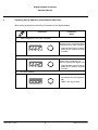
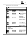
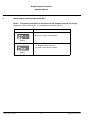
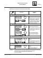
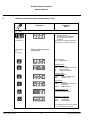
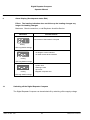
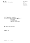
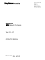
Raytheon Anschütz GmbH Postfach 1166 D -- 24100 Kiel Germany Tel +49--4 31--30 19--0 Fax +49--4 31--30 19--501 Email [email protected] www.raytheon--anschuetz.de Digital Repeater Compass Type 133 -- 811 OPERATOR MANUAL 3194E/133--811.DOC012 Edition: 02. Febr. 2000 Revised: Revised: May 10, 2007 Dec. 03, 2009 Weitergabe sowie Vervielfältigung dieser Unterlage, Verwertung und Mitteilung ihres Inhaltes nicht gestattet, soweit nicht ausdrücklich zugestanden. Zuwiderhandlungen verpflichten zu Schadenersatz. Copying of this document, and giving it to others and the use or communication of the contents thereof, are forbidden without express authority. Offenders are liable to the payment of damages. Toute communication ou reproduction de ce document, toute exploitation ou communication de son contenu sont interdites, sauf autorisation expresse. Tout manquement à cette règle est illicite et expose son auteur au versement de dommages et intérêts. Sin nuestra expresa autorización, queda terminantemente prohibida la reproducción total o parcial de este documento, así como su uso indebido y/o su exhibición o comunicación a terceros. De los infractores se exigirá el correspondiente resarcimiento de daños y perjuicios. Digital Repeater Compass Technical Documentation Operator Manual CONTENTS page Declaration of Conformity 1 General . . . . . . . . . . . . . . . . . . . . . . . . . . . . . . . . . . . . . . . . . . . . . . . . . . . . . . . . . . . . . . . 1 2 Notes on the Operating Instructions . . . . . . . . . . . . . . . . . . . . . . . . . . . . . . . . . . . . . . 2 3 4 Switching ON the Digital Repeater Compass . . . . . . . . . . . . . . . . . . . . . . . . . . . . . . Signalling during Operation (Development status E01) . . . . . . . . . . . . . . . . . . . . . . 3 4 5 Additional Operations (Development status E01) . . . . . . . . . . . . . . . . . . . . . . . . . . . 5 6 7 Alarm Display (Development status E01) . . . . . . . . . . . . . . . . . . . . . . . . . . . . . . . . . . Signalling during Operation (Development status E02) . . . . . . . . . . . . . . . . . . . . . . 6 7 8 Additional Operations (Development status E02) . . . . . . . . . . . . . . . . . . . . . . . . . . . 8 9 10 Alarm Display (Development status E02) . . . . . . . . . . . . . . . . . . . . . . . . . . . . . . . . . . Switching off the Digital Repeater Compass . . . . . . . . . . . . . . . . . . . . . . . . . . . . . . . 10 10 Edition: May 10, 2007 I 3194E/133--811.DOC012 Digital Repeater Compass Operator Manual Left blank 3194E/133--811.DOC012 II Edition: 02. Febr. 2000 Digital Repeater Compass Technical Documentation Operator Manual 1 General The Digital Repeater Compass is designed to indicate the ship’s heading referring to north, which has been ascertained by the Gyro/Magnetic compass (GPS/SAT for development status E02). The heading is read off at a 7--segment LCD display (luminous numerals). The Gyro (GPS/SAT development status E02) heading is shown in degrees and decimal degrees. The decimal digit is made smaller to prevent erroneous reading. Heading changes are indicated by a tendency indicator. Depending on the speed of the heading change, a ring consisting of bi--colour LCDs indicate a turn to starboard by green light and a turn to backboard by red light. The R.o.T. in the LED ring is proportional to the ship’s R.o.T. Further characteristics of the Digital Repeater Compass: -- Recognition of a RS 422 interface acc. to NMEA and therefore automatic change-over of the operation mode when heading serial is detected. -- Synchronisation unnecessary because transmission of absolute values LED ring Digital display Function keys Operator Manual This operator manual contains all operating instructions as well as a survey of possible warnings and alarms indicated on the digital display. Service Manual In addition to the operator manual a service manual is available. It contains: -- information about installation and first putting into operation -- information about maintenance and repair -- a description of the Digital Repeater Compass 3194E/133--811.DOC012 1 Edition: 02. July 1999 Digital Repeater Compass Operator Manual 2 Notes on the Operating Instructions The operation is interactive (action reaction). The operating procedure shown in the corresponding chapter is to be followed step by step. When necessary, helpful information in short form has been added to the figurative representation (symbols). Explanation of symbols: Key operation Action, general LED out LED on LED flashes Edition: 05. Mar. 1997 2 3194E/133--811.DOC012 Digital Repeater Compass Technical Documentation Operator Manual 3 Switching ON the Digital Repeater Compass With switching--on the ship’s supply the Digital Repeater Compass is ready for operation. There are two different types of displaying the information during normal operation, depending on the development status (E01 or E02). Development status E01 see sections 4, 5 and 6. Development status E02 see sections 7, 8 and 9. The development status of this Digital Repeater Compass is shown on a type plate on the side of the housing. 3194E/133--811.DOC012 3 Edition: May 10, 2007 Digital Repeater Compass Operator Manual 4 Signalling during Operation (Development status E01) With normal operation the following is indicated on the digital display: Indications ¡ Comments, Notes Valid Heading from the Gyro compass Indication of Gyro compass heading with graduation by tenth of degree: -- triggered LEDs in the ring light up green (turn to STBD) or red (turn to PORT) © Valid Heading from Magnetic compass Indication of Magnetic compass heading without graduation by tenth of a degree; with degree sign -- triggered LEDs in the ring light up green (turn to STBD) or red (turn to PORT) ¢ No Valid Heading -- horizontal lines in the digital display -- LEDs in the ring are dark Edition: May 10, 2007 4 3194E/133--811.DOC012 Digital Repeater Compass Technical Documentation Operator Manual 5 Additional Operations (Development status E01) Indications Comments, Notes Dimming ¡ e. g.: Continuous brightness adjustment: -- of the digital display -- of the key illumination -- of the tendency indicator (LEDs) It can be dimmed via an ex-ternal dimmer only, when the brightness has been set to minimum before. or or: Test © During pressing the key check of -- the LCD segments -- the LEDs at max. brightness -- the key illumination at max. brightness approx. 3s simultaneously Switch--back to heading indication is automatic after release of the keys. Switching on / off the Tendency Indicator ¢ During the test: -- Keep the key pressed -- Switch on/off the tendency indi-cator with the key Switch--back to heading indication is automatic after release of the keys. ’Freeze’ function for taking bearings with the bearing disc £ Requirement: An external push--button for the ’Freeze’ function is connected to the ’’REMOTE CONTROL’ terminals. e. g.: After pressing the push--button, the heading indication is not changed for 6s; during this time, the tendency indicator is continuously lit--up in yellow. Freeze Course external 3194E/133--811.DOC012 5 Edition: May 10, 2007 Digital Repeater Compass Operator Manual 6 Alarm Display (Development status E01) Effect: The heading indication do not follow up the heading changes any longer. Measures: Check connections, or call Raytheon Anschütz Service. Indications Possible Causes Cable of the interface interchanged flashing -- no telegram via the interface -- no cable contact at the interface flashing Edition: May 10, 2007 6 3194E/133--811.DOC012 Digital Repeater Compass Technical Documentation Operator Manual 7 Signalling during Operation (Development status E02) Indications ¡* Comments, Notes Valid Heading from the Gyro compass Indication of Gyro compass heading with graduation by tenth of a degree -- triggered LEDs in the ring light up green (turn to STBD, red (turn to PORT) or orange (turn to STBD or PORT) but the Gyro compass is still in the settling stage (up to 4h after switching on the Gyro compass). ©* Valid Heading from Magnetic compass Indication of Magnetic compass heading without graduation by tenth of a degree; with degree sign -- Triggered LEDs in the ring light up green (turn to STBD) or red (turn to PORT). Up from development status year 2010 the decimal digit of magnetic heading is displayed. ¢* Valid Heading from a GPS/SAT Indication of GPS/SAT--compass heading with graduation by tenth of a degree -- Triggered LEDs in the ring light up green (turn to STBD) or red (turn to PORT). £ No valid Heading -- horizontal lines in the digital display -- LEDs in the ring are dark (see service manual) *¡©¢ -- Heading information in the display is alternating with the information of the heading source, this feature can be switched OFF (see service manual). -- The LED ring (tendency indicator can be switched OFF (see service manual). 3194E/133--811.DOC012 7 Edition: Dec. 03, 2009 Digital Repeater Compass Operator Manual 8 Additional Operations (Development status E02) Indications ¡ Comments, Notes Test During pressing the keys, check of -- the LED segments -- the LEDs at max. brightness -- the key illumination at max. brightness Switch--back to heading indication is automatic after release of the keys. approx. 5s simultaneously During displaying “888.8” Read out (displaying) the configuration press right key Software status e.g. P008 E00.00 Heading source possible indications: GM = Gyro or Magnetic compass* G = Gyro compass* M = Magnetic compass Heading offset possible indications: 000 = Heading without offset 180 = Heading + 180 Data format possible indications: HSEr = Heading serial (Anschütz Coursebus) nMEA = NMEA Telegram Data transmission rate possible indications: 4.8, 9.6,19.2 or 38.4 kBaud Telegrams per second 1000 = 1 Telegram/s 0100 = 10Telegram/s 0020= 50 Telegram/s For configuration see service manual * G = also GPS/SAT compass Edition: May 10, 2007 8 3194E/133--811.DOC012 Digital Repeater Compass Technical Documentation Operator Manual Indications © Comments, Notes Dimming e.g.: Continuous brightness adjustment: -- of the digital display -- of the key illumination -- of the tendency indicator (LEDs) or or: It can be dimmed via an external dimmer only, when the brightness has been set to minimum before. ¢ ’Freeze’--Function for taking bearings with bearing disc Requirements: An external push--button for the ’Freeze’ function is connected to the ’REMOTE CONTROL’ terminals. e.g.: After pressing the push--button, the heading indication is not changed for 6 seconds; during this time the tendency indicator is continuously light--up in yellow. Freeze Course external 3194E/133--811.DOC012 9 Edition: May 10, 2007 Digital Repeater Compass Operator Manual 9 Alarm Display (Development status E02) Effect: The heading indication does not follow up the heading changes any longer. No heading changes. Measures: Check connections, or call Raytheon Anschütz Service. Indications Possible Causes Data content of the interface corrupted flashing LED ring flashes orange -- no telegram via the interface -- no cable contact at the interface flashing LED ring flashes orange flashing ----- System error Heading invalid Gyro error Magnetic compass error LED ring flashes orange 10 Switching off the Digital Repeater Compass The Digital Repeater Compass can be switched off by switching off the supply voltage. Edition: 05. Mar. 1997 10 3194E/133--811.DOC012