1
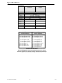
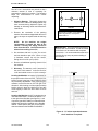
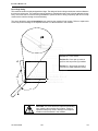
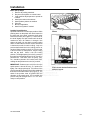
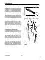
Product
Manual
9 3 7
SATELLITE
SET-UP and INSTALLATION
OPERATING SYSTEM
TROUBLESHOOTING
PARTS
DO NOT REMOVE
MANUAL FROM
MACHINE
Automatic Products ♦ 165 Bridgepoint Drive. ♦ South St. Paul MN 55075
937 Series V2.3 0608
Part # 9370003
TABLE OF CONTENTS
Warranty..............................................................................................................................................................ii
Introduction.........................................................................................................................................................iii
Features .............................................................................................................................................................iv
Installation ..................................................................................................................................................... 1.01
Cautions ........................................................................................................................................... 1.01
Unpacking ........................................................................................................................................ 1.02
Leveling the Machine ...................................................................................................................... 1.02
Door Hinge ....................................................................................................................................... 1.04
Set Up Steps .................................................................................................................................... 1.05
Optional Equipment....................................................................................................................................... 2.01
Components .................................................................................................................................................. 3.01
Lighting System................................................................................................................................ 3.01
Main Product Shelves ...................................................................................................................... 3.01
Delivery Bin ...................................................................................................................................... 3.01
Vend Motors ..................................................................................................................................... 3.01
Programming................................................................................................................................................. 4.01
Parts .............................................................................................................................................................. 6.01
Service/Trouble Shooting .............................................................................................................................. 7.01
To achieve the most trouble-free operation from your 937 Series Merchandiser, it is highly recommended that
this service manual be thoroughly read and the instructions followed pertaining to installation, servicing and
maintaining of the unit.
Should you have questions pertaining to this manual or the vendor, please contact your AP distributor or write
directly to:
Product Support Group
Automatic Products
165 Bridgepoint Drive
South St. Paul, MN 55075 USA
651-288-2975
651-288-2971 (fax)
© 2007 Automatic Products
937 Series V2.3 0308
i
V2.3
LIMITED EXPRESS WARRANTY
Automatic Products (AP) warrants these automatic merchandisers (the "Unit"), manufactured by it, to be free under normal use and
service from defects in material or workmanship for a period of two (2) years from the date of delivery of this Unit to the original
purchaser who purchased the Unit either directly from AP or from an authorized AP dealer or distributor (“AP Dealer/Distributor”). This
warranty extends only to the original purchaser of the Unit, but only if purchased either directly from AP or from an authorized AP
Dealer/Distributor (“Original Purchaser”), and is limited to the repair or replacement, at AP's sole option, of any part or parts of the Unit
that are returned to AP or to the authorized AP Dealer/Distributor from whom the Unit was originally purchased, with all transportation
charges prepaid by Original Purchaser, and which, on AP's examination, such returned part or parts shall conclusively appear to have
been defective. This warranty does not extend to:
1.
Any Unit, or part thereof, that was subjected to misuse, neglect, or accident by anyone other than AP after its delivery to the
Original Purchaser;
2.
Any Unit, or part thereof, that was modified, altered, incorrectly wired or improperly installed by anyone other than AP or used in
violation of the instructions provided by AP;
3.
A Unit, or part thereof, which has been repaired or altered by anyone other than AP or an authorized AP Dealer/Distributor;
4.
A Unit, or part thereof, which has had the serial number removed, defaced, or otherwise altered;
5.
Any plastic or glass windows, lamps, fluorescent tubes, and water contact parts;
6.
Any Unit used outdoors;
7.
Any accessories used with the Unit that were manufactured by some person or entity other than AP; or
8.
Any Unit repaired within the warranty period with parts other than genuine AP built or endorsed parts.
AP DISCLAIMS ALL OTHER WARRANTIES OF ANY KIND AS TO THE UNIT AND ALL
WARRANTIES OF ANY KIND AS TO ANY ACCESSORIES. THIS DISCLAIMER OF
WARRANTIES INCLUDES (1) ANY EXPRESS WARRANTIES OTHER THAN THE
LIMITED WARRANTY PROVIDED ABOVE AS TO THE UNIT AND (2) ALL IMPLIED
WARRANTIES OF MERCHANTABILITY AND FITNESS FOR A PARTICULAR PURPOSE
AS TO THE UNIT AND ANY ACCESSORIES. UNDER NO CIRCUMSTANCES SHALL AP
BE RESPONSIBLE FOR ANY INCIDENTAL, CONSEQUENTIAL OR SPECIAL
DAMAGES, LOSSES OR EXPENSES (INCLUDING BUT NOT LIMITED TO LOST
PROFITS, LOST SALES, INJURY TO PERSON OR PROPERTY) ARISING FROM OR IN
CONNECTION WITH THE USE OF, OR THE INABILITY TO USE, THE UNIT FOR ANY
PURPOSE WHATSOEVER REGARDLESS OF THE LEGAL THEORY (CONTRACT,
TORT OR OTHER). IN NO EVENT WILL AP BE OBLIGATED TO PAY DAMAGES FOR
ANY AMOUNT EXCEEDING THE PRICE PAID FOR THE UNIT. No representative of AP or any other
person is authorized to assume for AP, or agree to on the behalf of AP, any other liability or warranty in connection with the sale of this
Unit.
AP reserves the right to make any changes or improvements in its products without notice and without obligation, and without being
required to make corresponding changes or improvements in Units theretofore manufactured or sold.
165 Bridgepoint Drive
South St. Paul, MN 55075 USA
651-288-2975
651-288-2971 (fax)
937 Series V2.3 0308
ii
V2.3
INTRODUCTION
The 937 Series features simple operation and built in flexibility, as well as extensive diagnostics and error
reporting facilities to provide ease of maintenance.
HOW TO USE THIS MANUAL
This manual is divided into seven basic parts:
1.
Unpacking and Installation.
2.
Optional Equipment.
3.
Components.
4.
Operating System.
5.
Programming.
6.
Parts.
7.
Troubleshooting.
CAUTION: Certain procedures in both the operating section and the service
section require that voltage be on in the machine. Only trained personnel
should perform this function. Exercise extreme caution while performing these
procedures. These procedures will be marked with the lightening bolt symbol
as it appears at left.
CAUTION: Certain procedures in both the operating section and the service
section require a qualified trained technician to perform the particular task at
hand. These procedures will be marked with the exclamation symbol as it
appears at left.
937 Series V2.3 0308
iii
V2.3
Features
FEATURES OF THE 937 MERCHANDISER
STANDARD FEATURES
28 selections.
Flexible spiral spacing for large products.
Eight-point star drive motor.
OPTIONS
Delivery bin cushion.
Base kit.
Lexan window.
NOISE LEVEL
Operates at less than 70 db (A).
ACCEPTABLE AMBIENT OPERATING
TEMPERATURE RANGE.
All equipment manufactured by Automatic
Products is designed to work properly in a
temperature range of 10°C to 38°C (50°F to
100°F) in still air (75% R.H. non-condensing).
The machine is being stored in a temperature
range of -18°C to 68°C (0°F to 155°F).
iv
V2.3
Shelf Configurations
The 937 Satellite is available in the follow shelf configurations.
5 – Single Snack
1 - Candy
4 – Single Snack
2 - Candy
6 - Single Snack
6 - Candy
937 Series V2.3 0608
3 – Single Snack
3 - Candy
v
V2.3
Shelf Configurations
5 - Dual Snack
1 - Candy
4 - Dual Snack
2 - Candy
6 - Dual Snack
3 - Dual Snack
3 - Candy
937 Series V2.3 0608
vi
V2.3
Specifications
Specifications
937
Domestic
937
Export
Height
72" 183 cm
Width
33.5" 88 cm
Depth
35" 89cm
Floor Space
8.1 Sq. Ft.
Container Size
58.1 Cu Ft
.75 Sq Meter
1.65 Cu Meter
Voltage (AC)
120V
230V
Hertz
60Hz
50Hz
Standby
Amperes
Running
Amperes
Watts
0.7A
.35A
3A
1.5A
Shipping Weight
360W
495 lbs
345W
225 kg
495 lbs
225 kg
937
SNACK SPIRALS
10 – Item Spiral 1-7/8”
12 – Item Spiral 1-9/16”
15 – Item Spiral 1-7/32”
937
CANDY SPIRALS
15 – Item Spiral 1-1/8”
18 – Item Spiral 15/16”
24 – Item Spiral 11/16”
5 - Item Spiral 4-1/8”
6 – Item Spiral 3-3/32”
7 – Item Spiral 2-21/32”
18 – Item Spiral 1”
30 – Item Spiral 1/2”
40 – Item Spiral 5/16”
5 – Item Spiral 4-1/8”
6 – Item Spiral 2-7/8”
7 – Item Spiral 2-1/2”
9 – Item Spiral 1-15/16”
10 – Item Spiral 1-3/4”
12 – Item Spiral 1-1/2”
40 – Item Spiral 3/16”
SPIRAL DEPTH CHART
Spirals highlighted in bold are standard production spirals.
All other spirals are available through aftermarket parts only.
937 Series V2.3 0608
vii
V2.3
Installation
Cautions
The following cautionary information should be reviewed before the machine is installed. Following these
requirements and warnings are required.
CAUTION: This machine is designed for indoor usage only. Any other usage will void
the Manufacturers Warranty.
Voltage and Polarity Check
It is important that this machine is hooked up to the proper voltage and polarity for
your country. Use a voltmeter to verify voltage and polarity before connecting the
machine to a wall outlet. For machines located in North America, use the diagram
below to verify correct voltages. Should the reading be any different than a normal
reading or if you are unsure of what the reading should be contact an electrician.
CAUTION: Any procedure marked with the symbol at left requires that the Machine
have the power applied and a shock hazard exists.
CAUTION: Different countries may have unique plug arrangements. Ensure that the
machine is properly grounded before operating.
CAUTION: The power cord for all machines manufactured for use outside of North
America are of a type Y attachment. If the power cord is damaged, it must be replaced
by the manufacturer, its service agent, or a similarly qualified person in order to avoid
a hazard.
CAUTION: The machine is a heavy item. Ensure that sufficient personnel are available
for lifting and transporting the machine. Use proper lifting procedures and equipment.
CAUTION: The system components in this machine utilize static sensitive
components. Precautions for handling sensitive devices should be observed when
handling these items.
Voltage and Polarity Check (for Machines located in North America Only)
It is important that this machine is hooked up to proper voltage and polarity. Using a voltmeter, perform the
following checks from the illustration below.
937 Series 0208
1.01
V2.3
Installation
The 937 Line is assembled and packed so that a
minimum amount of time is necessary for
preparation to install it on location. The following
steps are recommended to insure correct
unpacking.
A
1. Shipping Damage: Thoroughly inspect the
exterior of the carton for damage which may
have occurred during shipment. Report any
damage to delivering carrier and follow their
instructions.
C
B
DOOR
2. Remove the remainder of the packing
material. On machines shipped with the lock in
place, the keys are taped inside the delivery
bin.
NOTE:
On the machine, the weight
concentration is toward the back of the
cabinet. Trucking and lifting should be
done from the back. CAUTION should be
taken when trucking from side.
3. On machines with lock in place, first unlock
and turn handle to open door. When no lock
is furnished, remove clip and turn handle.
Swing door to its full open position.
Place level in position A, and adjust the
bottom leg levelers, and repeat in
positions B & C
IMPORTANT: A set of anchoring brackets is
included with each machine. This kit is located
in the bottom of the machine with complete
instructions. It is recommended that this kit be
installed during set-up to prevent shifting of
the machine.
4. Remove all additional packing material from
the machine.
5. Warranty: The warranty card is attached to
the cover of this manual. It must be filled out
in full and mailed at once to insure coverage.
1 ½ Inches
Leveling the Machine on location is important for
the proper function of the machine. There are four
leveling screws in the legs of the machine to make
any necessary adjustments. After positioning the
machine, level it from front to rear and right to left
directions. After leveling, turn front right (lock side)
leveling screw in about one-half turn to drop this
corner slightly to make the door easier to close
and lock.
Locating the Machine the 937 is designed to be
used with a Bev-Max 2. It should be placed 1 ½”
to the right of the Bev-Max (see figure A). A set
of spacers (part # 9371008) is included with the
Satellite and should be installed on the Satellite
cabinet. These spacers will give you the proper
clearance between the BevMax and Satellite.
Figure A: 1 ½ inches separation between
the 2 machines is required.
937 Series 0208
1.02
V2.3
Installation
Connecting the Machine on location is
required. To do this, locate the interconnect
harness coming out of the back side of the
Satellite cabinet and route it into the back of the
Bev-Max up to the control board and plug into
the J16 plug. Only 1 Satellite can be operated off
of a Bev-Max 2.
Figure B: Location of J16
937 Series 0208
1.03
1.02
V2.3
Installation
Door Hinge Swing
This machine contains a newly designed door hinge. The design of the door hinge controls the maximum distance
the door can swing open. The maximum opening position is reached when the screw is forced against the hinge
body. This screw can be removed during installation to permit the door to swing completely open and can help
maneuver the machine through a narrow doorway.
The screw should be replaced immediately upon reaching the machine’s final location. Failure to replace this
screw may result in damage to an adjacent machine or to the harnesses in the machine.
D
Position A – Door Closed.
Position B – Door open to nominal
position with stop screw (D) installed.
C
Position C – Stop screw removed to
permit door to reach maximum swing.
260°
A
126°
B
CAUTION: The screw should be replaced immediately
upon reaching the machines final location. Failure to
replace this stop may result in damage to an adjacent
machine or the harnesses in the machine.
937 Series 0208
1.04
V2.3
Installation
Basic Set Up Steps
1. Remove all packing materials.
2. Set prices and options on control board.
3. Load machine adjust spacers or spirals as
needed.
4. Install price tabs on the shelves.
5. Install product pushers as needed.
6. Coin test.
7. Bill test if applicable.
8. Install lock cylinder if needed.
Loading Snack Shelves
Open the main door to its full open position. While
pushing down on the plastic lock lever located on
the right side of the shelf, grasp the shelf under
both front corners (see Figure 1). Lift the front of
the shelf slightly and pull forward until the shelf
reaches its stop. On shelves 1 through 4 the
shelves tilt down (do not drop) to make loading
easier. A new feature in the 937 Series, the bottom
2 shelves do not tilt for easier loading. Only one
product shelf should be in the loading position at
any time. When returning a shelf, be sure the shelf
is in its full home or vend position. Begin loading
with the top shelf. Move it into the loading
position. The height spacing for items is greatest in
this shelf and the tallest bagged items should be
placed there. Soft items, such as pastry, pies,
etc., should be placed in the lowest snack shelf,
making the drop distance as short as possible.
IMPORTANT: Product must not be forced into the
spiral spaces it should fit freely. If a product fits
tightly, use a larger pitch spiral. The bottom of the
product should be placed on top of the spiral wire
that rests on the shelf surface (see Figure 2). The
width of the product must be greater than the
diameter of the snack spiral. If it is smaller, the
product may fall through when it is in the front,
ready to vend position.
937 Series 0208
Figure 1: Moving shelf into the loading
position
Figure 2: Placement of product on main
product snack shelves and front end
position of spiral.
1.05
V2.3
Installation
Adjusting the Stopping Position of the Spiral
One primary difference that distinguishes the 937
motor from previous motors is an eight sided star
at the drive hub of the motor. This permits the
stopping position of the spiral to be customized by
the operator to ensure the best possible delivery of
each product. To change the stopping position of
the spiral, remove the spiral lock from the motor by
pinching the shaft of the spiral lock from the back
side of the motor and pulling forward on the front
side of the spiral lock.
The spiral lock can be reinstalled in any of eight
different positions by turning the spiral lock to the
position desired and pushing the shaft of the spiral
lock through the eight sided star at the drive hub of
the motor.
Figure 3: Removing and installing spiral.
Removal/Replacement of Spiral
Grasp the front of the spiral and turn it clockwise.
Lift the spiral up and off of the spiral lock. When
replacing a spiral attach it around the tab on the
spiral lock and turn the spiral counterclockwise to
lock it in place. Be sure the front end of the spiral
is positioned properly (with the front end of the
spiral pointing downward on the left side) (see
figure 3). Pull lightly on the front of the spiral to
ensure it is locked in place.
Product Spacers - 4 Selection Shelf
A product spacer is used to reduce the width of the
product area. This feature should be used on any
4-selection single spiral snack shelf where the
product width is 4" or less. Spacers should fit
within 1/8" of the product but should not fit tight
against the product. There are three positions in
each snack space where these spacers can be
placed. To install the spacer, align the lock ears
(on the lower edge of the spacer) with one of the
three sets of slots (one front and one rear). (see
Figure 4.) Push the spacer to the rear to allow the
ears to enter the slots, then allow the spacer to
move forward. Be sure the ears are in the same
set of slots; front and rear (see Figure 4).
Continue loading all spirals; adjust spacers where
needed in the top shelf. Return the top shelf to the
vend position and follow this procedure to load the
remainder of the large spiral shelves.
937 Series 0208
Figure 4: Alignment of movable product
spacers.
1.06
V2.3
Installation
Loading Main Product Candy Shelves
The 8 selection (candy type) shelves are loaded
similarly to the 4-selection shelves except that the
bottom of the product sits on the shelf in front of
the spiral wire (see Figure 5). These products must
also fit properly, and the product should fit freely:
do not force product into spiral.
Figure 5: Placement of product on candy
shelves and front end position of spiral.
937 Series 0208
1.07
Product Spacers - 8 Selection Shelf
The 8 selection shelves are equipped with a product
spacer (see Figure 6) that can be pivoted from the
right side of every other product space. These
spacers should be pivoted out to hold the product
upright, but not tight against the product. Leave about
1/8" clearance between the spacer and the product.
Figure 6: Candy shelf product spacer
positioned to hold candy upright.
V2.3
Installation
Product Pushers
Included with the machine are enough pushers for
you to install a pusher on each candy spiral. This
plastic part is designed to push the top of the
product forward while it is vending, helping it fall
from the shelf. It can also be used with products
that have the wrapper end flap on the outside of
the package. In this case, the pusher prevents
these products from hanging on the spiral by
spreading the flap. The pusher should be installed
at approximately the 1 o’clock position on the
spiral with the tab extending forward (see Figure
7). Locate the pusher in its proper position, hold it
against the spiral wire and push the semi-circular
part around the spiral wire. Black pushers (part
#440215) are used on left hand spirals and white
pushers (part #440141-1) are used on right hand
spirals. Note: Not every selection spiral will need a
product pusher. (Example - Box Items.)
Figure 8: Fold bagged items bottom edge
forward and up.
Cigarette Vending from the 937 Series
Cigarettes can be vended from the candy shelves
using a (15 capacity) spiral for the soft pack regular,
king, 100 MM or 120 MM packs. A (12 capacity)
spiral should be used for (box) packs.
Lock Product Shelves
When all of the product has been loaded be sure all
shelves are returned to their vend position behind the
front roller guide.
Figure 7: Location of product pusher on
spiral.
Bagged or Boxed Items
Vending small bagged items in the 8-selection
shelves if not loaded properly could be a problem.
The sealed edge of the bag may get under the
spiral wire causing the product to hang up after it
has been vended. It is recommended that the
lower edge of these types of product be folded
forward and up (see Figure 8) next to the product
before inserting into the spiral space. It is also
recommended to use a slightly larger count spiral
for bagged items because of the product settling to
the bottom of the package.
937 Series 0208
1.08
Cleaning
The 937 series will do the best merchandising job for
you if it is kept clean. The display window can be
cleaned with any good glass cleaner. The exterior
and interior surfaces should be cleaned with warm
water and mild detergent. Rinse thoroughly and dry
all surfaces.
CAUTION: Do not use any cleaners containing silicon
as this could cause electrical failures.
The main product shelves can be best cleaned with
the spirals and product spacers removed. Refer to
page 1.04 for removal of spirals and removal of the
product spacers.
V2.3
Optional Features
Ventilating Fan (Part #750102-4 =120 Volts) (Part
#750102-5 = 240 Volts) Export
This ventilating fan keeps a steady flow of air
moving through the vendor cabinet. Installation of
the fan takes only a few minutes. All vendors are
wired with a fan plug on the junction box for easy
installation.
Base Kits
Base kits are available to make the vendor
compatible with other manufacturers.
Dual Spiral Motors (Part # 360240)
Snack shelves can be set up to have dual spiral
selections. The dual spirals will help vend specialty
items better. These motors are available through
aftermarket parts only.
Half Cycle Motors (Part #360241)
The half cycle motors are used to vend thin items.
This motor is used with a product divider that is
positioned down the center of the coil. The product
is placed on both the left and right hand side of the
coil. When the motor turns, it turns only 180 degrees
(half revolution) rather than 360 degrees (full
revolution). These motors are available through
aftermarket parts only.
Delivery Bin Cushion
A delivery bin cushion is available for use when
vending heavy or fragile items.
Lexan Window
A Lexan window is available as a direct replacement
for tempered glass.
937 Series 0208
2.01
V2.3
Components
High Efficiency Lighting System
Energy Star ballast & T5 bulb provide increased
lighting, exceptional light distribution, and present
products in their true, vibrant colors.
Main Product Shelves
There are either five or six main product shelves per
machine. Each selection has its own motor
mounted to the back of the shelf. Every shelf has its
own harness and plug for connecting to the
remainder of the circuit through the cabinet
receptacle, located in the rear right of the cabinet.
The motors are the same on either shelf. It is
possible to exchange a five selection shelf with a ten
selection shelf or visa versa. You also have the
capability to gain one inch either up or down on any
shelf. To do this the shelf should be removed and
the cabinet back harness receptacle lowered or
raised along with the right & left shelf tracks.
Each selection on a shelf will have the same
common shelf wire - all shelf harness use wire #12
as a shelf common. This corresponds to the
selected shelf wire in the cabinet harness. The
terminal for the shelf common in the harness is the
smaller of the two.
Selection numbers are assigned from left to right,
starting with selection 0. Each selections number
corresponds to the number of the wire for that
selection.
Selection numbers in the 937 Series Machines
support a three digit selection system. The first digit
indicates the cabinet number, the second digit is the
shelf number and the third digit is the selection
number on that shelf.
Note
♦ When exchanging the shelves, you will not need
any parts but you will have to reprogram the
machines prices.
Delivery Bin
This is located below the display window on the door
and is mechanically operated. Should the door
become difficult to operate, place a small amount of
grease on the arm tracks.
Part #
360275
360276
Case Color code
1/2 blue, 1/2 white, 8 point
star drive
1/2 blue, 1/2 grey, 8 point
star drive
Description
CW food/Snack
motor
CCW Food/Snack
motor
937 Motor Part Number Chart
Shelf 21
Vend Motors
The vend motors used in the 937 Series machines
have been specifically developed to operate with the
AP Control System. One primary difference that
distinguishes the new motors from previous motors
is the presence of an eight sided star at the drive
hub of the motor. This permits the stopping position
of the spiral to be customized by the operator to
ensure the best possible delivery of product. Motors
are of the fast trac style, with all electronics required
to correctly operate the motor contained inside the
gear case or the motor housing and no external
control board. Each of the motors used with the 937
Control System will have two terminals. The two
terminals continue to be used to identify the shelf
and column (selection) to be vended.
Shelf 22
Shelf 23
Shelf 24
Shelf 25
Shelf 26
Each motor requires two wires to operate correctly.
These wires are: shelf common, and selection.
OOOOOOOOOO
0
1
2
3
4
5
6
7
8
9
Selection Wire Number
12 12 12 12 12 12 12 12 12 12 Shelf Common Number
Figure 14: Shelf numbering guide.
937 SHELF WIRING DIAGRAM
937 Series 0208
3.01
V2.3
Programming
Service Modes
To access the service modes for the Satellite, open
the door on the Bev-Max and press the Service
Switch located on the right top of the control board 5
times (see Figure 9). The display will show “Satellite
Mode” (Figure 10).
Satellite Mode
Figure 10: Initial Service Mode Screen
Entering one of the Service Mode letters shown on
the following page allows you access to that Service
Mode.
IMPORTANT:
The Bev-Max 2 requires
revision 566 or higher software to operate a 937
Satellite.
Satellite Service Modes
To access these modes press the Service
Switch on the BevMax 5 times then press
the corresponding letter or number.
Figure 9: Location of the Service Switch
B - Test Vend
C - Set Price
D – Enable Combo Discount
E – Set Combo Discount
F – Set Cup Model
1 – Set Golden Eye Policy
2 – Set Golden Eye Selections
3 – Check Motor Scan
Figure 11: Bev-Max Selection Pad
937 Series 0208
4.01
V2.3
Programming
Mode 5-B – Test Vend
Mode 5-B is used to test vend the selections in the
Satellite machine. To access this mode, press the
Service Switch 5 times, then press B on the
selection keypad the display will show “Sat Test
Vend”.
Sat Test Vend
Mode 5-B – Test Vend Initial Screen
Press the * key the display will show “enter
selection”. Enter the selection number on the keypad
then press the * key to run the motor. Upon
completion the display will show “Continue? *=Y
CLR=N”. Press the * key to continue testing or press
the CLR key to end the test and return to the “Sat
Test Vend” screen.
Mode 5-C – Price Assignment
Mode 5-C is used to assign the regular and
secondary prices for all selections in the Satellite
machine. Secondary prices are only active when the
vender is in the Happy Hour mode. To access this
mode, press the Service Switch 5 times, then press
C on the selection keypad the display will show “Set
Sat Price”. Press the * key the display will show “1 =
Regular Pricing” in the top line and “2 = Secondary
Pricing” in the second line. Use the selection keypad
to enter which set of prices you want to change.
Note:
The following steps are the same for both
“Regular Pricing” and “Secondary Pricing.” The
following steps assume you are setting the
“Regular Pricing.”
Then follow one of the procedures below to set
prices.
All Selections
Upon pressing the 1 key the display will show
“Regular $XX.XX”. Enter the desired price using the
selection keypad the display will change to “PR $
XX.XX” with XX.XX being the price you just entered.
Press the * key a > will appear under PR $ on the
display. Press the * key the display will ask “ALL
Prices Set Ok?” Press the * key to accept or press
the CLR key to go back one step without saving the
price.
By Shelf
Upon pressing the 1 key the display will show
“Regular $ XX.XX”. Enter the desired price using the
selection keypad the display will change to “PR $
XX.XX” with XX.XX being the price you just entered.
Press the * key a > will appear under PR $ on the
display. Enter the first 2 digits of any selection on the
shelf that you are changing (example enter 21 if you
want to price the entire top shelf). Press the * key
the display will ask “SET SHELF X OK?” Press the *
key to accept or press the CLR key to go back one
step without saving the price.
937 Series 0208
4.02
Set Sat Price
Mode 5-C Price Assignment Initial Screen
1 = Regular Pricing
2 = Secondary Pricing
Mode 5-C Price Assignment Second Screen
Field A
Regular
$
.XX
Mode 5-C Price Assignment Third Screen
Field A is the price setting field.
Field A
PR$
.XX
>
Mode 5-C Price Assignment Fourth Screen
Field A is the price you set in the third screen.
V2.3
Programming
By Selection
Upon pressing the 1 key the display will show
“Regular $ XX.XX”. Enter the desired price using the
selection keypad the display will change to “PR $
XX.XX” with XX.XX being the price you just entered.
Press the * key a > will appear under PR $ on the
display. Enter the selection number on the keypad.
Press the * key the display will ask “Price XXX ok?
Press the * key to accept and continue entering
selections at that price or press the CLR key to go
back one step without saving.
Mode 5-D – Enable Combo
Discount
Field A
PR$
.XX
SET PRICE XXX OK?
Field B
Mode 5-C Price Assignment FITH Screen
Field A is the price you set in the third
screen.
Field B is the change price verification
SAT EN COMBO DISCOUNT
Mode 5-D is used to enable/disable the Combo
Discount. To access this mode, press the Service
Switch 5 times, then press D on the selection
keypad the display will show “Sat En Combo
Discount”.
Mode 5-D – Enable Combo Discount Initial
Screen
Press the * key the display will show the current
Combo Discount setting. Press the * key to turn the
Combo Discount on or off. Press the CLR key to
return to the menu heading.
IMPORTANT: The multivend option on the
BevMax must be enabled for the Combo
Discount to function.
Field A
COMBO DISCOUNT: OFF
PRESS “ * ” -
TURN ON
Field B
Mode 5-D – Screen 2 Enable Combo
Discount
Field A is discount on/off setting field.
Mode 5-E – Set Combo Discount
Mode 5-E is used to set up the Combo Discount. To
access this mode, press the Service Switch 5 times,
then press E on the selection keypad the display will
show “Sat Set Cmbo Discnt”.
Press the * key the display will show Combo PR .00,
use the selection keypad to enter the discount
amount. Press the * key, the display will change to
PR$ .XX where .XX is the dollar amount you just
entered. Press the * key to accept the discount
amount or press the CLR key to go back one step.
937 Series 0208
4.03
SAT SET CMBO DISCNT
Mode 5-E – Set Combo Discount Initial
V2.3
Programming
Field A
Mode 5-E – Continued
Note
♦ The discount amount applies to ALL selections
in both the Satellite and BevMax.
♦ Selections can be made in either order –
beverage first, then snack or vice versa.
COMBO PR
.00
Mode 5-E – Screen 2 Combo Discount
Amount
Field A
Mode 5-F – Set Cup Model
Mode 5-F is used to set the Cup Model being used
in the BevMax. For more information please see the
BevMax Technical Manual.
COMBO PR
.XX
SET DISCOUNT.
OK?
Field B
Mode 5-E – Screen 3 Combo Discount Amount
Field A is the discount amount field. Where .XX is
the amount you set in step 2.
Field A is the set up verification field.
Field A
Mode 5-1 – Set Golden Eye Policy
Mode 5-1 is used to set the Golden Eye Policy. To
access this mode, press the Service Switch 5 times,
then press 1 on the selection keypad the display will
show “Golden - Eye Policy”.
Press the * key the display will show the current
Golden Eye setting on the top line and ‘*’ = XXX,
where XXX is the alternate setting either Drop or
Home. Press the * key to change to the alternate
setting.
Notes:
♦ This mode only sets the operating condition of
Golden Eye.
♦ Selections are enabled/disabled in Mode 5-2.
MODE:
‘*’ = HOME
Field B
Mode 5-1 – Screen 2 Golden Eye Policy on Drop
Field A is the current Golden Eye Setting when set to
drop.
Field B is the instructions to change to home.
Field A
MODE:
GOLDEN – EYE POLICY
ON DROP
ON HOME
‘*’ = DROP
Field B
Mode 5-1 – Golden Eye Policy Initial Screen
Mode 5-1 – Screen 2 Golden Eye Policy on Home
Field A is the current Golden Eye Setting when set to
home.
Field B is the instructions to change to drop.
937 Series 0208
4.04
V2.3
Programming
Mode 5-2 – Set Golden Eye
Selections
SET GOLDEN-EYE SEL
Mode 5-2 is used to set up the Golden Eye
Selections. To access this mode, press the Service
Switch 5 times, then press 2 on the selection keypad
the display will show “Set Golden Eye Sel”.
Press the * key the display will show the selections
currently active for Golden Eye in the top line, if
necessary press the * key to see any subsequent
screens. If no selections are currently enabled, the
display will show “None Assigned”. The factory
default for Golden Eye is all selections enabled.
Press the * key the display will show “Enter Start
Location” use the selection keypad to enter the
selection number. Press the * key and the display
will show “Enter End Location”, use the selection
keypad to enter the ending location. See notes
below for further explanation.
Notes:
♦ To Set Single Selections: Enter the same
starting and ending locations.
♦ To Set Entire Shelves: In the Start Location
enter 2X* where X represents the shelf number.
The display will change to the ending location
screen with the last selection of that shelf
already displayed. Press * to set.
♦ To Set Entire Machine: In the Start Location
enter 2* the display will change to show the
selection range of the machine in the top line
and “Continue? *=Y” in the bottom line. Press *
to set.
♦ To Set a Range of Selections: Enter the
starting selection number into the Start
Location then enter the last selection number
into the End Location. Press * to set.
Rules: Single Selection, Range, Shelf or Entire
Machine
♦ When enabling or disabling single selections
the opposite state of the current setting will be
used. For example: if you currently have
selection 210 enabled and you go into change
it, it will change to disabled.
♦ When enabling or disabling a range, shelf or
the entire machine. The setting will change to
the opposite of the lowest selection number in
the range, shelf or machine being set. For
example if you are changing the top shelf, and
selection 210 is set to enable while 212 -216
are set to disable, then you would be
disabling the top shelf from Golden Eye
because the lowest selection number on the
shelf was set to enable.
937 Series 0208
4.05
Mode 5-2 – Set Golden Eye Selections
Initial Screen
Field A
XXX-XXX
PRESS * TO CONTINUE
Mode 5-2 – Screen 2 Set Golden Eye Selections
Field A is the currently enabled Golden Eye
selections.
ENTER START LOCATION
XXX
Field A
Mode 5-2 – Screen 3 Set Golden Eye Selections
Field A is the starting selection number entry field.
ENTER END LOCATION
XXX
Field A
Mode 5-2 – Screen 4 Set Golden Eye Selections
Field A is the ending selection number entry field.
Field A
Field B
XXX – XXX
YYYYY
CONTINUE? * Y
Mode 5-2 – Screen 5 Set Golden Eye Selections
Field A is the starting and ending selection number
entry field.
Field B is the action field; either enabled or disabled.
V2.3
Programming
Mode 5-3 – Check Motor Scan
Mode 5-3 is used to verify the state of the selection
motors in the Satellite. To access this mode, press
the Service Switch 5 times, then press 3 on the
selection keypad the display will show the results of
the last Motor Scan Test. Press the * key to scroll
through the results.
To initiate a new scan of the motors Press the 1 key.
The display will say Scanning Motors when
completed the display will say Scanning motors
done press * to continue. Press the * key to scroll
through the results.
CHECK MOTOR SCAN
Mode 5-3 – Check Motor Scan
Initial Screen
MOTOR SCAN RESULTS
GOOD MOTORS: XX
Field A
Mode 5-3 – Check Motor Scan
Field A is the number of motors reporting as good.
MOTOR SCAN RESULTS
BAD MOTORS: XX
Field A
Mode 5-3 – Check Motor Scan
Field A is the number of motors reporting as
MOTOR SCAN RESULTS
MISSING MOTORS: XX
Field A
Mode 5-3 – Check Motor Scan
Field A is the number of motors reported as missing.
937 Series 0208
4.06
V2.3
Programming
Mode 3-3 – Set Not Available Time
This mode works in conjunction with Mode 2-3
“Not Available Mode.”
Mode 3-3 is used to set timed machine shutdown
periods. To access this mode, press the Service
Switch 3 times, then press 3 on the selection keypad
the display will show “Set Not Avail Time”. Press the
* key and the display will show “Select Block (1-4)”.
There are 4 different shutdown time blocks
available. Choose the number of the block you want
to edit by pressing the corresponding number (1-4)
on the selection keypad.
Upon entering the block number, the display will
show the current shutdown setting with the starting
hour highlighted. Using the numeric key pad set the
starting hour (using 24 hour military clock) in Field A.
Field B will now be highlighted, use the numeric key
pad to enter the starting minute. The days of the
week shown in Field C will now be highlighted. To
change the setting to no press key 2, to yes press
key 1. The highlighting will move one day at a time
until all days are set, then the stop time hour Field D
will be highlighted. Use the numeric key pad to enter
the ending hour (using 24 hour military clock). Field
E will now be highlighted, use the numeric key pad
to enter the ending minutes. The display will now
show “OK? * = Y CLR = N”. Press the * key to
continue, the display will show the currently
assigned selections. Press the * key to continue, the
display will show “Enter Selections”. Use the
selection keypad to enter the selections. See notes
below for further explanation.
Notes:
♦ To Set Single Selections: Enter the selection
number then press the * key, the display will
show you whether you are Enabling or Disabling
the selection. Press the * key to continue
entering selections or the CLR key to return to
“Set Not Avail Time”.
♦ To Set Entire Shelves: Enter 2X* where X
equals the shelf number, the display will show
you whether you are Enabling or Disabling the
selection. Press the * key to continue entering
shelves or the CLR key to return to “Set Not
Avail Time”.
♦ To Set Entire Machine: Enter 2* the display will
show you whether you are Enabling or Disabling
the selection. Press the * key to continue
entering selections or the CLR key to return to
“Set Not Avail Time”.
Additional Notes:
♦ Enabled = selection use will NOT be allowed
during the shutdown.
♦ Disabled = selection use will be allowed
during the shutdown.
937 Series 0208
4.07
SET NOT AVAIL TIME
Mode 3-3 – Set Not Available Time Initial Screen
SELECT BLOCK (1-4)
Mode 3-3 – Screen 2 Set Not Available Time
Field B
START
08:00
Field D
MTWTFSS
YYYYNNN
Field A
Field C
ON State
STOP
16:00
Field E
Field C
OFF State
Mode 3-3- Screen 3 Set Not Available Time
Field A is the shutdown starting hour set field.
Field B is the shutdown starting minute set field.
Field C is the day of the week selection field. In
this example Monday, Tuesday, Wednesday and
Thursday are ON and Friday, Saturday and
Sunday are OFF.
Field D is the shutdown ending hour set field.
Field E is the shutdown ending minute set field.
Field A
XXX
PRESS ‘*’ TO CONTINUE
Mode 3-3 – Screen 4 Set Not Available Time
Field A shows the currently set selections.
V2.3
Programming
♦
This mode is password protected. Before
entering or changing this setting you must
enter the password if one has been
assigned.
♦
You must enable the shutdown block in
mode 2-3 in order for the shutdown to
become active.
♦
Shut down blocks are allowed to cross
over midnight.
Field A
ENABLED
CONTINUE? * = Y CLR = N
Mode 3-3 – Screen 5 Set Not Available Time
Field A is the current action field.
NOT AVAILABLE MODE
Mode 2-3 – Not Available Mode
Mode 2-3 is used to turn on/off the shut downs set in
Mode 3-3. To access this mode, press the Service
Switch 2 times, then press 3 on the selection keypad
the display will show “Not Available Mode”. Press
the * key and the display will show “Select Block (14)”. Press the number of the block you want to edit
by pressing the corresponding number (1-4) on the
selection keypad.
Upon entering the block number, the display will
show the current state of the shutdown either on or
off. Press the * key to change the shutdown setting
to the alternate state either on or off.
Field A
SELECT BLOCK (1-4)
Mode 2-3 – Screen 2 Set Not Available Time
Field A
Field B
Field B
NOT AVAILABLE X: ON
NOT AVAILABLE X: OFF
PRESS ‘*’ – TURN OFF
PRESS ‘*’ – TURN ON
Field A
Field A
Mode 2-3 – Screen 3 Set Not Available Time
Shown in the Off State
Field A – is the shutdown block number 1 – 4.
Field B – is the shutdown block current state. In this
example the shutdown is turned off.
Field C – is the instructions to change the state of
the shutdown.
937 Series 0208
Mode 2-3 – Set Not Available Time Initial Screen
4.08
Mode 2-3 – Screen 3 Set Not Available Time
Shown in the On State
Field A – is the shutdown block number 1 – 4.
Field B – is the shutdown block current state. In this
example the shutdown is turned on.
Field C – is the instructions to change the state of
the shutdown.
V2.3
Programming
This Page Intentionally Left Blank
937 Series 0208
4.08
V2.3
Parts
Door – Inside Front
6.02
Cabinet
6.04
Cabinet
6.06
Shelf Accessories
6.09
Snack Shelf
6.10
Candy/Paired Shelf
6.12
Driver Board Asm
6.08
Delivery Bin
6.14
937 Trim
6.16
937 Series 0208
6.01
V2.3
Square – Inside Front
34
937 Series 0608
6.02
V2.3
Square – Inside Front
Key
1
3
4
5
6
7
8
9
10
11
12
NS
15
16
18
19
20
21
22
23
24
25
26
27
28
29
30
31
32
33
34
NS
NS
NS
NS
NS
NS
NS
NS
937 Series 0608
Description
Door Weldment, Euro, Black
T-Handle Asm, Black
Lock Arm Asm
Window, Front Ambient 44-5/8 x 21-9/16 x 1/8
Note: Replacement Glass Must be Hard Tempered
Locally Obtained Lexan only.
Edging, Window Ambient Glass, 134 Inches
Clamp, Window Hinge Side
Clamp, Window Lock Side
Locking Bar Asm
Spring, Locking Bar
Screw Self Tap, .850 Long
Clamp, Window, Bottom
Tape, Reflective, Bottom Window Clamp
Foam, Adhesive Backed
Wire Saddle, Locking Top
Screw, 8-32 x 5/16 PH/NIBS
Screw, Self Tap, .480 Long
Delivery Bin Asm, w/Golden Eye, See Page 6.14
Washer, #8
Screw, 8-32 x 3/8 PN/NIBS
Bolt, 10-24 x 3/4 Carriage
Nut, 10-24 Keps
Screw, 6-32 x1 /4 Phillips Pan Head
Fluorescent Lamp, F24T5/841/HO
Harness Asm, High Output Light
Harness Asm, Lamp to Cabinet (Not Shown)
Harness Asm, Adapter to Power Cord (Not Shown)
Nut, 6-32 Keps ZN
Screw, 6-32 x 3/8 Phillips Pan Head
Screw, 6-32 x 1/4 Phillips Pan Head
Cord Clip, Adhesive Back
Cable Clamp, Adhesive Back, 1/2 inch
Tape, Reflective, 4 x 22 3/4
Bracket, Top Window
Graphics Coin Return Decal
Graphics Val Decal
Graphics MIAC Price Stickers
Graphics MIAC Save Circ LG
Graphics MIAC Upper
Graphics MIAC Right Wing
Graphics MIAC Left Wing
Graphics MIAC Save Cir SM
6.03
937
9372008
17200002-02
640131
750141-1
460436
12000718
202118
16000101
400112
13100054-01
12000844
17400178-01
460041
13100044
276-8R5
13100054
600-8
276-8R6
118-10-12
438-10
116-6R4
26900004
16800149
680456-1
9371003
438-6
276-6R6
276-6R4
420097
420096-1
17400177
12000741
9371013
9371014
9371015
9371016
9371017
9371018
9371019
9371020
V2.3
Cabinet
16
15
13
1
14
12
10
21
20
11
9
8
2
7
3
5
4
6
18
19
4
17
4
937 Series 0608
6.04
V2.3
Cabinet
Key
1
2
3
4
5
6
7
7A
8
9
10
11
12
13
14
15
16
17
18
19
20
21
NS
NS
937 Series 0608
Description
Cabinet Asm, Complete w/legs. See Page 6.06
Filler Plate, Left Front
Door Filler, Specify Color
Screw, 8-32 x 3/8 Pan Head
Shelf Support, Left Front
Assembly, Shelf Cabinet Track, Left
Rail Insert, Left or Right, Used on Bottom 2 Shelves Only
Screw, Undercut Flat Head for Rail Insert
Assembly, Shelf Cabinet Track, Right
Harness, Cabinet Back, Asm Complete
Mounting Bracket Only, Cab Back Harness
Screw, Shoulder 8-32 x 3/8
Assembly Complete, High Efficiency Light Ballast & Filter
T5 120V
Ballast w/Harness, F24T5HO
Line Filter
Line Cord, GFCI, 14/3, 15Amp
Bushing, Strain Relief
Filler Panel, Gum & Mint, for use with no Gum & Mint
Screw, Undercut Flat Head for Shelf Rail
Panel, Filler
Switch, Door
Cable, Communications Asm
Harness, Com Cable Ch 35” FDB to Power Board
Cabinet Spacer Assy
6.05
937
12000825
600310
276-8R6
12000819
16400077
14400128
13100060
16400075
9371003
12000863
13100064
16600442
16800146
380303
16800153
380052-2
12000798
13100060
9371000
23800003
16600324
680659-1
9371008
V2.3
Cabinet
1
16
21
22
20
15
14
10
11
5
4
2
5
6
3
6
9
5
8
6
7
937 Series 0608
6.06
V2.3
Cabinet
Key
1
2
3
4
5
6
7
8
9
10
11
14
14A
15
16
20
21
22
937 Series 0608
Description
Cabinet Asm, Complete w/legs, Specify Color
Rear & Front Pivot Side Leg Weldment, Specify Color
Front Leg Weldment, Pivot Side, Specify Color
Front Leg Weldment, Lock Side, Specify Color
Screw, Hex Head 5/16 -18 x 3/4
Leg Leveler
Lower Hinge Support, Specify Color
Washer
Lower Hinge, Pivot Asm
Door Catch Asm
Screw, Pan Head, 8-32 x 3/8
Screw, Hex head, 5/16-18 x 7/16
Nut, Keps ¼-20
Bracket, PCB Mounting, See Page 6.08
Cover Plate Asm
Screw, Hinge Stop
Upper Hinge Asm
Screw, Torx Tap, 1/4-20 x 1/2
6.07
937
600195
600195
600197
420187
300103
202088
420010-24
640154
12000290
276-8R6
164-51-7
438-41
9330634
13100057
16400079
13100035
V2.3
Driver Board Assembly
4
1
5
3
6
2
Key
1
2
3
4
5
6
937 Series 0608
Description
Assembly, Complete, Driver Board
Driver Board
Software, Flash Chip (Not Shown)
PCB, Power Supply
Bracket, PCB Mounting
Standoff, Circuit Board, ¼”
Screw, Phil Pan HD #6 x 1/2
Harness, Door Switch (Not Shown)
Harness, Communication Cable (Not Shown)
Harness, Com Cable FDB to Power Board
35”(not Shown)
6.08
Part No.
9371002
9376000
9376001
1816005
9371001
17100003
218-6R8
9379002
16600324
680659-1
V2.3
Shelf Accessories
Shelf Spiral Charts
Single Snack Spirals
Candy Spirals
Left Hand
Right Hand
5 ct 14000004-01
14000003-01 6 ct
400167-1
7 ct
400178-1
400164-1
8 ct
400179-1
9 ct
400169-1
400166-1
10 ct
400170-1
400168-1
12 ct
400171-1
400120-1
14000015 15 ct
400121-1
14000016 16 ct
18 ct
400122-1
20 ct
24 ct
400123-1
30 ct
400135-1
40 ct
400138-1
5 ct 14000002-01
6 ct
400162-1
7 ct
400153-1
8 ct
10 ct
400127-1
12 ct
400128-1
15 ct
400129-1
18 ct
400163-1
30 ct
400136-1
40 ct
400137-1
Key Description
Part No.
NS Product Pusher, Right Hand
NS Product Pusher, Left Hand
440141-1
440215
Product Rail Chart
Can Rail - Low
937
12000822
Half Cycle Rail
937
Candy Rail
937
16600449
937 Series 0608
12000823
Can Rail - High
937
Pastry Rail
937
16600451
6.09
12000824
Small Product Rail
937
16600452
V2.3
Snack Shelf
5
7
5A
9
6
3
2
1
10
4
11
8A
8
937 Series 0308
6.10
V2.3
Snack Shelf
Key Description
1 Assembly, complete, Pastry shelf w/single blue/white motors (cw)
Pastry shelf, Weldment, only.
2 Screw, shelf roller.
3 Shelf roller
4 Nut, keps (1/4 x 28)
5 Shelf motor, CW, (Blue/white)
5A Spiral retainer. white, right hand (RH)
6 Assembly, complete. Harness with bracket. 4 selections.
Harness, only. 4 selection shelf.
7 Screw, Ph. T-23 (8-32 x 5/16)
8 Assembly, Shelf Spacer
8A Spring Only, Shelf Spacer
Extension, Shelf Spacer (not shown)
9 Decal, use with convertible shelf.
10 Selection tabs, Numbers 210’s, Snack
Selection tabs, Numbers 220’s, Snack
Selection tabs, Numbers 230’s, Snack
Selection tabs, Numbers 240’s, Snack
Selection tabs, Numbers 250’s, Snack
Selection tabs, Numbers 260’s, Snack
11 Price Label, Self Scrolling, $.40 - $2.40
Price Label, Self Scrolling, $2.40 - $4.35
937 Series 0308
6.11
937
16600417-01
16000336
300203
440362
437-41
360275
460405
660435-9
16800073
276-8r5
16600416
14400116
202770
460494
9370009
9370010
9370011
9370012
9370013
9370014
17400153
80388674001
V2.3
Candy / Paired Shelf
6
6A
5A
5
11
10
8
9A
7
3
2
9
4
1
12
937 Series 0308
13
6.12
V2.3
Candy / Paired Shelf
Key Description
1 Assembly,complete.Paired motor candy shelf. Used with a combination of
clockwise motors cw (blue/white) and counter clockwise motors ccw (blue/gray)
Candy shelf, Weldment only.
2 Screw, shelf roller
3 Shelf roller
4 Nut, keps (1/4x28)
5 Vend motor complete. Clockwise CW (blue/white)
5A Spiral retainer. White, right hand (RH)
6 Vend motor complete. Counter clockwise CCW (blue/gray)
6A Spiral retainer. Gray, left hand (LH)
7 Assembly, complete. Harness with bracket. 8 selections
Harness only. 8 selections
8 Screw, PH.T-23 (8-32x5/16)
9 Assembly, shelf spacer
9A Spring Only, Shelf Spacer
10 Assembly, candy shelf slide
11 Decal, use with candy convertible shelves
12 Selection tabs, Numbers 210’s, Candy
Selection tabs, Numbers 220’s, Candy
Selection tabs, Numbers 230’s, Candy
Selection tabs, Numbers 240’s, Candy
Selection tabs, Numbers 250’s, Candy
Selection tabs, Numbers 260’s, Candy
13 Price Label, Self Scrolling, $.40 - $2.40
Price Label, Self Scrolling, $2.40 - $4.35
937 Series 0308
6.13
937
16600417-04
16000336
300203
440362
437-41
360275
440405
360276
440406
660435-10
16800074
276-8r5
16600416
14400116
16600389
460494
9370018
9370019
9370020
9370015
9370016
9370021
17400153
80388674001
V2.3
Delivery Bin
13
10
15
4
5
11
14
17
9
12
6
2
8
7
1
3
937 Series 0308
6.14
16
V2.3
Delivery Bin
Key Description
1
Bin Asm Complete, Black Door, w / Golden Eye
Plastic Bin only
2
Delivery Bin Door - Black
3
Inner Door - Standard
Inner Door - Steel
4
Bin Door Drive - Pivot
5
Inner Bin Door Arm
6
Bin Door Drive Arm
7
Bin Door Washer
8
Door Bearing
9
Golden Eye II Receiver Board
9A Cover, Golden Eye, Lock Side
10 Golden Eye II Transmitter Board
10A Cover, Golden Eye, Hinge Side
Harness Gold Eye Interconnect (Not Shown)
Harness Gold Eye, GE to Control Board (Not Shown)
11 Lens, Golden Eye, Lock & Hinge Side
12 Washer-# 8
13 Retaining Ring 3/8
14 Screw, Pan Hd Mach 4-40 X 3/8
15 8-32x3/8 Ph Pan Hd M/S Zn
16 #4-40 Hex M/S Nut Nylon
17 Barrier Guard, Stiffener Asm
Nut, 8-32 Keps, used with item 17 (Not Shown)
NS Delivery Bin Pad (Not Shown)
937 Series 0308
6.15
937
9370601
16400072
440373-1
12000784
12000784-02
16400076
16400070
640097
420282
440129
13600020-01
12000835
13600022-01
12000836
16800101
9379003
14400101
600-8
751-37
116-4R6
116-8R6
13100028
16400093-01
438-8
12200124
V2.3
937 Trim & Panels
Top Panel
Top Trim
Top Graphic
Top Vinyl
Door Edging
Vertical
Window
Trim
Vertical
Window
Trim
Outside
Vertical
Trim
Outside
Vertical
Trim
Left
Side
Graphic
Horizontal
Window
Trim
Right
Side
Graphic
Bottom Vinyl
Door Edging
Delivery
Door Trim
Lower
Graphic
C
D
937 Series Trim Profile Chart
937 Series 0308
6.16
V2.3
937 Trim & Panels
937 Trim & Panels
Top Trim
AP Style - Silver
AP Style – Black
937 Series 0308
Profile Part #
Qty Dimensions
13400021-05 1 1.872 x 21.657 in
13400021-06 1 1.872 x 21.657 in
Outside Vertical Trim
Silver
Black
D
D
9372011
13400030
2
2
65.609 Inches
65.609 Inches
Window Horizontal Trim
Silver
Black
C
C
13400013-04
13400013-05
1
1
21.656 Inches
21.656 Inches
Window Vertical Trim
Silver
Black
C
C
13400013
13400013-01
2
2
65.406 Inches
65.406 Inches
Delivery Door Trim
Silver
Black
C
C
13400013-04
13400013-05
1
1
21.656 Inches
21.656 Inches
Bottom Vinyl Door Edging
Edging
201678-2
Top Vinyl Door Edging
Edging
201678-7
1
Trim Screws
Self Tap x .480 Long
13100054
40
Top Panel
Top Trim Insert - Black
14400146-06
1
Graphic - Splash Decals
Top
Right Side
Left Side
Lower
9372003
9372004
9372005
9372007
1
1
1
1
6.17
29.938 Inches
7.484 Inches
1.70 x 21.602 in
V2.3
Service
937 Paired Motor Shelf Conversion Instructions
These instructions provide the steps to convert two candy selections on a paired motor candy shelf to a
single dual spiral snack selection, or visa versa.
Convert Two Candy Selections to One Snack
1) Remove product from 2 adjacent spirals –
Left hand motor must be an even number.
2) Remove divider from between the 2 spirals,
and store under machine for future use.
3) Remove the selection number tabs from both
selections
4) Remove one of the 2 scrolling price tabs rolls
5) Move the remaining scrolling price tab to
position C on drawing below.
6) Store removed tabs and scrolling price roll in
the service envelope, and retrieve the
correctly numbered selection tab from the
extras provided in the service envelope.
7) Install the new selection tab on the front of
the shelf.
8) Count the number of spaces in each spiral to
verify that they are the same. Change spiral if
required.
9) Load product in selection.
10) Access Mode 23, and pair the motors
11) Access Mode 20, and set the new price, and
adjust the scrolling price tab as required.
12) Test vend with money to ensure correct
operation
937 Series 0608
7.01
Convert One Snack to Two Candy
Selections
1) Remove product from spirals.
2) Install divider between the 2 spirals, between
positions B & C.
3) Remove the selection number tab from the
selection.
4) Remove the scrolling price roll.
5) Locate the extra selection tabs and scrolling
price rolls in the service envelope, and
retrieve the correctly numbered selection
tabs and a scrolling price roll from the service
envelope.
6) Install the scrolling price rolls in positions B
and D.
7) Install the two selection tabs on the front of
the shelf in positions A, B and C, D
8) Load product in selections.
9) Access Mode 23, and disable the paired
motors.
10) Access Mode 20, and set the new price for
both selections, and adjust the scrolling price
tabs as required.
11) Test vend with money to ensure correct
operation.
V2.3
Service
Removal of Delivery Bin
1 Turn the power to the machine off.
1) Disconnect the ribbon cables from either side of
the delivery bin, and remove the ribbon cable
from the clips on the sides of the bin. The ribbon
cable should remain attached to the door
weldment.
2) Disconnect the control harness from machine
harness to the Golden Eye board.
3) Remove the 2 screws and washers securing the
bin on either side of the glass, reference Photo
1.
4) Remove the 2 screws and washers attaching
the bin to the lower door stiffener, reference
Photo 2.
5) Remove the bin from the inside of the door by
lifting up from the inside of the door.
6) Assembly is reverse of disassembly.
Photo # 1
Photo # 2
937 Series 0608
7.02
V2.3
Bev-Max Software Update Instructions
CAUTION: The system components in this machine utilize static
sensitive components. Precautions for handling sensitive devices
should be observed when handling these items.
1. Note any required meter readings or options set.
2. Press the Service Mode button three times.
3. Press Key “8”
Note: If a password has been programmed in SETUP MODE 1, you will be prompted to enter it before
proceeding to the next step.
4. EPROM Removal:
a. Power down the vender. Ground yourself on the vender cabinet before removing the EPROM
from the ESD tube or control board.
b. If an EPROM is present in the control board, remove the existing EPROM.
Note: An EPROM does not need to be in the control board after the control board has been
programmed. The EPROM can be used to program other boards.
c. Verify the pins of the new EPROM are not bent before installing in the EPROM Socket.
d. Install the new EPROM in the EPROM socket. Ensure the EPROM is oriented correctly with its
reference marker in the same direction as the reference marker of the EPROM socket. Do not
rely on the EPROM label for orientating the EPROM.
5. Automatic Reprogramming:
a. Turn power on to the vender. When auto-updating the display will show old version for a few
seconds while the red LED on the control board blinks.
b. Display will change to “EPROM UPGRADE…” for approximately 10 seconds with the green LED
rapidly blinking.
c. Display will change to new version software with red LED blinking at a steady heart beat rate.
6. Manual Reprogramming (only used if EPROM does not automatically reprogram):
a. At power up, the current software version will be displayed. To manually program the control
board with the new software, press the service switch on the control board to enter service
menus. Advance to “UPDATE SOFTWARE”. Press the * key. Display will show “Reprogramming
Vendor” while the yellow LED blinks.
b. Display will show new software revision, then return to stand by. This confirms that the new
software has been successfully updated.
Note: to remove the EPROM after programming, remove power to
the vender, ground yourself on the vender cabinet before removing
the EPROM, remove the EPROM, while still grounded install a label
on the microprocessor showing the revision of software that is
installed in the controller, power the vender back on and test for
proper operation.
Bev-Max Board
Shown as installed
in machine.
Location of EPROM socket
937 Series 0608
7.03
V2.3
5
4
3
2
1
SHELF 1
16800106
D
P1
1
2
3
4
5
6
TO
BEV
MAX
SELECTIONS 210 - 217
P2
680659-1
P1
POWER / MDB
THERE IS A
UNUSED
4 PIN CONNECTOR
FROM THIS HARNESS
D
SHELF 2
POWER
BOARD
1816005
SELECTIONS 220 - 227
P5
MOTOR DRIVE
4 MOTOR
SHELF HARNESS
16800073
SHELF 3
GOLDEN EYE
EMITTER BOARD
13600022
C
SELECTIONS 230 - 237
P3
BAFFLE
9379003
GOLDEN EYE
SENSOR BOARD
13600020
8 MOTOR
SHELF HARNESS
16800074
SHELF 4
C
SELECTIONS 240 - 247
STANDARD
SNACK
MOTORS
9379002
16800101
P4
SERVICE
SHELF 5
26900004
SELECTIONS 250 - 257
FDB
BOARD
360250
LIGHT
SHELF 6
9379000
SELECTIONS 260 - 267
DOOR SWITCH
23800003
B
DOOR
GROUND
B
1
2
3
4
16800149
CABINET
GROUND
BALLAST
ASSEMBLY
16600442
680456-1
1
2
3
1
2
3
LINE
CORD
9379001
1
2
3
1
2
3
1
2
3
1
2
3
REV
TITLE
REVISION DESCRIPTION
THIS DOCUMENT CONTAINS INFORMATION
WHICH IS PROPRIETARY TO CMS
MANUFACTURING. NO REPRODUCTION OR
PUBLICATION OF THIS DOCUMENT IN WHOLE OR
IN PART SHALL BE MADE WITHOUT THE
WRITTEN APPROVAL OF CMS MFG.
A
TOLERANCES (EXCEPT AS NOTED)
X
+/- 0.500
X.X
+/- 0.250
HOLE DEC. +/- --X.XX +/- 0.125
X.XXX +/- 0.062 ANGLES +/- ---
DATE
MERCHANDISING
SYSTEMS
CABINET
GROUND
5
4
3
BY
DATE
E.C.O.
SATELLITE WIRING DIAGRAM
ST. LOUIS, MO
63044 - 1200
2
DRAWN BY
3/27/07
A CRANE CO. COMPANY
SHEET
1
OF
DOCKTER
SIZE
1
DO NOT SCALE
DRAWING
B
CHECKED BY
HUDIS
PART NUMBER
9379004
1
REV
01
A