1
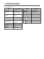
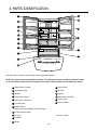
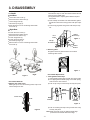
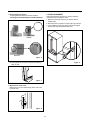
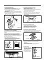
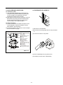
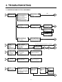
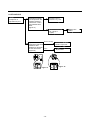
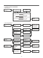
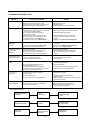
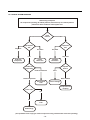
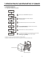
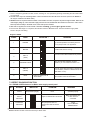
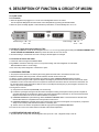
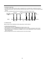
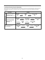
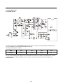
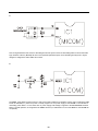
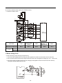
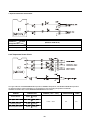
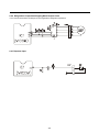
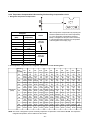
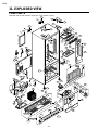
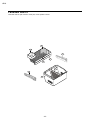
REFRIGERATOR
SERVICE MANUAL
CAUTION
BEFORE SERVICING THE UNIT,
READ THE SAFETY PRECAUTIONS IN THIS MANUAL.
MODELS:
LFC22760**
CONTENTS
SAFETY PRECAUTIONS -------------------------------------------------------------------------------------------SPECIFICATIONS -----------------------------------------------------------------------------------------------------PARTS IDENTIFICATION -------------------------------------------------------------------------------------------DISASSEMBLY ---------------------------------------------------------------------------------------------------------DOOR -----------------------------------------------------------------------------------------------------------------DOOR ALIGNMENT -----------------------------------------------------------------------------------------------FAN AND FAN MOTOR -------------------------------------------------------------------------------------------DEFROST CONTROL ASSEMBLY ----------------------------------------------------------------------------LAMP ------------------------------------------------------------------------------------------------------------------CONTROL BOX - REFRIGERATOR --------------------------------------------------------------------------MULTI DUCT ----------------------------- --------------------------------------------------------------------------ADJUSTMENT ----------------------------------------------------------------------------------------------------------COMPRESSOR ----------------------------------------------------------------------------------------------------PTC-STARTER -----------------------------------------------------------------------------------------------------OLP (OVERLOAD PROTECTOR) -----------------------------------------------------------------------------TO REMOVE THE COVER PTC --------------------------------------------------------------------------------CIRCUIT DIAGRAM ----------------------------------------------------------------------------------------------------TROUBLESHOOTING -------------------------------------------------------------------------------------------------COMPRESSOR AND ELECTRIC COMPONENTS --------------------------------------------------------PTC AND OLP ------------------------------------------------------------------------------------------------------OTHER ELECTRICAL COMPONENTS ---------------------------------------------------------------------SERVICE DIAGNOSIS CHART --------------------------------------------------------------------------------REFRIGERATION CYCLE --------------------------------------------------------------------------------------OPERATION PRINCIPLE& REPAIR METHOD OF ICE MAKER -------------------------------------------
8
8
8
9
9
10
11
11
12
13
14
15
17
DESCRIPTION OF FUNCTION & CIRCUIT & CIRCUIT OF MICOM ------------------------------------REFRIGERATOR EXPLODED VIEW & SERVICE PARTS LIST ------------------------------------------
20
41
SAFETYPRECAUTIONS
Pleasereadthefollowinginstructionsbeforeservicingyour
refrigerator.
7.Beforetiltingtherefrigerator,removeallmaterialsfrom
onorintherefrigerator.
1.Checktherefrigeratorforcurrentleakage.
2.Topreventelectricshock,unplugbeforeservicing.
8.Whenservicingtheevaporator,wearglovestoprevent
injuriesfromthesharpevaporatorfins.
3.Alwayschecklinevoltageandamperage.
4.Usestandardelectricalcomponents.
9.Serviceontherefrigeratorshouldbeperformedbya
qualifiedtechnician.Sealedsystemrepairmustbe
performedbyaCFCcertifiedtechnician.
5.Don'ttouchmetalproductsinthefreezerwithwet
hands.Thismaycausefrostbite.
6.Preventwaterfromspilingontoelectricelementsorthe
machineparts.
-2-
2
3
4
5
5
6
7
7
7
7
7
1. SPECIFICATIONS
22 cu. Ft. (22.4 cu. Ft.)
ITEMS
ITEMS
SPECIFICATIONS
SPECIFICATIONS
DOOR DESIGN
Side Rounded
VEGETABLE TRAY
Opaque Drawer Type
DIMENSIONS
W(836)x D(870)x H(1754) mm
W(32.91)x D(34.25)x H(69.06) in
COMPRESSOR
PTC Starting Type
EVAPORATOR
Fin Tube Type
127.5 Kg
281.09 pounds
CONDENSER
Wire Condenser
REFRIGERANT
R-134a (120 g)
NET WEIGHT
COOLING SYSTEM
Fan Cooling
LUBRICATING OIL
ISO10 (220 ml)
TEMPERATURE CONTROL
Micom Control
DEFROSTING DEVICE
SHEATH HEATER
Full Automatic
DEFROSTING SYSTEM
Heater Defrost
DOOR FINISH
REFRIGERATOR
60 W (2EA)
FREEZER
60 W (1EA)
LAMP
Embossed Metal, PCM Smooth,
Stainless
HANDLE TYPE
Bar
INNER CASE
ABS Resin
INSULATION
Polyurethane Foam
- 3-
2. PARTS IDENTIFICATION
L
A
M
B
C
N
D
E
O
F
G
H
P
I
Q
J
K
Use this section to become more familiar with the parts and features.
NOTE: This guide covers several different models. The refrigerator you have purchased may have some
or all of the items listed below. The locations of the features shown below may not match your model.
A Digital Sensor Control*
L Filter (Inside)*
B Refrigerator Light
M Dairy Bin
C Shelves
N Egg Box
D Temperature Contro*l
O Refrigerator Door Rack
E Chef Fresh / Snack Pan
P Freezer Light
Q Pull out Drawer
F Can Dispenser
G Optibin Crisper
Keeps fruits and vegetable fresh and crisper
H Customcube Icemaker*
I Ice Tray *
*on some models
J Durabase
K Divider
-4-
3. DISASSEMBLY
2. Remove gasket bracket clips
There are two clips on each door. Start bracket removal
near one of the middle clips.
1) Pull gasket back to expose gasket bracket clip and
door frame.
2) Insert a flat tip screwdriver into seam between gasket
bracket and door frame and pry back until clips snaps
out.
3) Continue prying back along seam until all clips snap
out.
3-1 DOOR
Left Door
Loosen the cover screw (1).
Disconnect door switch wire (2).
Loosen hinge bolts (3).
Lift off the top hinge (4).
Place the door on a non-scratching surface with
the inside up.
Right Door
Loosen the cover screw (1).
Disconnect door switch wire (2).
Disconnect wire harness (5).
Loosen hinge bolts (3).
Loosen ground screw (6).
Lift off the top hinge (4).
Place the door on a non-scratching surface with
the inside up.
Gasket
Bracket Clip
Door
Frame
Figure 3
Flat Tip
Screwdriver
Gasket
Bracket
3. Remove gasket
Pull gasket free from gasket channel on the three
remaining sides of door.
Figure 4
Left
Right
Door Gasket Replacement
1. Insert gasket bracket clips
1) Insert gasket bracket edge beneath door frame edge.
2) Turn upper gasket bracket spring so that both spring
ends are in the door channel.
3) Push in clip until you hear it snap securely into place.
Figure 1
Door Gasket Removal
1. Remove door frame cover
Starting at top of cover and working down, snap cover
out and away from door.
Gasket
Bracket Clip
Spring
Frame Cover
Door
Frame
Handle
Correct
Incorrect
Figure 5
4) Push in remaining two clips until you hear each snap
securely into place.
Note: Make sure that no part of gasket bracket edge
protrudes from beneath door frame edge.
Figure 2
- 5-
2. Insert gasket into channel
1) Snap gasket assembly into the door bracket.
<Inserting the Gasket Assembly into the Bracket Door>
3-2 DOOR ALIGNMENT
If the space between your doors is uneven, follow the
instructions below to align the doors:
1. With one hand, lift up the door you want to raise at
middle hinge.
2. With other hand, use pliers to insert snap ring as shown.
3. Insert additional snap rings until the doors are aligned.
(Three snap rings are provided with unit.)
Correct
Incorrect
Figure 6
2) Press gasket into channels on the three remaining
sides of door.
Figure 9
Figure 7
3. Replace door frame cover
Starting at top of cover and working down, snap cover
back into door.
Figure 8
-6-
3-3 FAN AND FAN MOTOR
3-5-1 Refrigerator Compartment Lamp
1. Remove the freezer shelf. (If your refrigerator has an
icemaker, remove the icemaker first)
2. Remove the plastic guide for slides on left side by
unscrewing phillips head screws.
3. Remove the grille by removing one screw and pulling the
grille forward.
4. Remove the Fan Motor assembly by loosening 2 screws
and disassembling the shroud.
5. Pull out the fan and separate the Fan Motor and Bracket.
1. Unplug the power cord from the outlet.
2. Remove refrigerator shelves.
3. Release the hooks on both ends of the lamp shield and
pull the shield downward to remove it.
4. Turn the lamp counterclockwise.
5. Assembly is the reverse of disassembly. Replacement
bulb must be the same specification as the original
(Max. 60 W2EA).
FAN MOTOR
BRACKET
MOTOR
Figure 15
FAN
3-5-2 Freezer Compartment Lamp
1. Unplug refrigerator or disconnect power.
2. Reach behind light shield to remove bulb.
3. Replace bulb with a 60-watt appliance bulb.
4. Plug in refrigerator or reconnect power.
Figure 11
GRILLE
3-6 CONTROL BOX-REFRIGERATOR
1. First, remove all shelves in the refrigerator, than remove
the Refrigerator control Box by loosening 2 screws.
3-4 DEFROST CONTROL ASSEMBLY
Defrost Control assembly consists of Defrost Sensor and
FUSE–M.
The Defrost Sensor works to defrost automatically. It is
attached to the metal side of the Evaporator and senses its
temperature. At 72°C, it turns the Defrost Heater off.
Fuse-M is a safety device for preventing over-heating of
the Heater when defrosting.
1. Pull out the grille assembly. (Figure 12)
2. Separate the connector with the Defrost Control
assembly and replace the Defrost Control assembly
after cutting the Tie Wrap. (Figure 13)
GRILLE ASSEMBLY
CONTROL BOX
COVER LAMP
Figure 16
DEFROST-CONTROL
ASSEMBLY
2. Remove the Refrigerator Control Box by pulling it
downward.
3. Disconnect the lead wire on the right position and
separate the lamp sockets.
3-7 MULTI DUCT
Figure 12
1. Remove the upper and
lower Caps by using a flat
screwdriver, and remove 2
screws. (Figure 17)
Figure 13
3-5 LAMP
2. Disconnect the lead wire
on the bottom position.
Figure 17
Figure 14
--7-
4. ADJUSTMENT
4-2-3 PTC-Applied Circuit Diagram
Starting Method for the Motor
4-1 COMPRESSOR
4-1-1
ジ
Role
The compressor intakes low temperature and low pressure
gas from the evaporator of the refrigerator and compresses
this gas to high-temperature and high-pressure gas. It then
delivers the gas to the condenser.
OVERLOAD PROTECTOR
N
4-1-2 Composition
The compressor includes overload protection. The PTC
starter and OLP (overload protector) are attached to the
outside of the compressor. Since the compressor is
manufactured to tolerances of 1 micron and is hermetically
sealed in a dust and moisture-free environment, use
extreme caution when repairing it.
C
2
PTC
5
S
L1
3
6
PTC STARTER
4-1-3 Note for Usage
(1) Be careful not to allow over-voltage and over-current.
(2) If compressor is dropped or handled carelessly, poor
operation and noise may result.
(3) Use proper electric components appropriate to the
Particular Compressor in your product.
(4) Keep Compressor dry.
If the Compressor gets wet (in the rain or a damp
environment) and rust forms in the pin of the Hermetic
Terminal, poor operation and contact may result.
(5) When replacing the Compressor, be careful that dust,
humidity, and soldering flux don’t contaminate the inside
of the compressor. Contamination in the cylinder may
cause noise, improper operation or even cause it to
lock up.
Resistance Starter Capacitor Running
COMPRESSOR
MOTOR
M
M
S
SEALED
TERMINAL
Figure 17
4-2-4 Motor Restarting and PTC Cooling
(1) It requires approximately 5 minutes for the pressure to
equalize before the compressor can restart.
(2) The PTC device generates heat during operation.
Therefore, it must be allowed to cool before the
compressor can restart.
4-2-5 Relation of PTC-Starter and OLP
(1) If the compressor attempts to restart before the PTC
device is cooled, the PTC device will allow current to
flow only to the main winding.
(2) The OLP will open because of the over current
condition. This same process will continue (3 to 5
times) when the compressor attempts to restart until
the PTC device has cooled. The correct OLP must be
properly attached to prevent damage to the
compressor.
Parts may appear physically identical but could have
different electrical ratings. Replace parts by part
number and model number. Using an incorrect part
could result in damage to the product, fire, injury, or
possibly death.
4-2 PTC-STARTER
4-2-1 Composition of PTC-Starter
(1) PTC (Positive Temperature Coefficient) is a no-contact
semiconductor starting device which uses ceramic
material consisting of BaTiO3.
(2) The higher the temperature is, the higher the resistance
value. These features are used as a starting device for
the Motor.
4-2-6 Note for Using the PTC-Starter
(1) Be careful not to allow over-voltage and over-current.
(2) Do not drop or handle carelessly.
(3) Keep away from any liquid.
If liquid such as oil or water enters the PTC,
PTC materials may fail due to breakdown of their
insulating capabilities.
(4) If the exterior of the PTC is damaged, the resistance
value may be altered. This can cause damage to the
compressor and result in a no-start or hard-to-start
condition.
(5) Always use the PTC designed for the compressor and
make sure it is properly attached to the compressor.
Parts may appear physically identical but could have
different electrical ratings. Replace parts by part
number and model number. Using an incorrect part
could result in damage to the product, fire, injury, or
possibly death.
4-2-2 Role of PTC-Starter
(1) The PTC is attached to the Sealed Compressor and is
used for starting the Motor.
(2) The compressor is a single-phase induction motor.
Durign the starting operation, the PTC allows current
flow to both the start winding and main winding.
-8-
4-3 OLP (OVERLOAD PROTECTOR)
4-4 TO REMOVE THE COVER PTC
4-3-1 Definition of OLP
(1) OLP (OVERLOAD PROTECTOR) is attached to the
Compressor and protects the Motor by opening the
circuit to the Motor if the temperature rises and
activating the bimetal spring in the OLP.
(2) When high current flows to the Compressor motor, the
Bimetal works by heating the heater inside the OLP,
and the OLP protects the Motor by cutting off the
current flowing to the Compressor Motor.
4-3-2 Role of the OLP
(1) The OLP is attached to the Sealed Compressor used
for the Refrigerator. It prevents the Motor Coil from
being started in the Compressor.
(2) For normal operation of the OLP, do not turn the Adjust
Screw of the OLP in any way.
1) Remove the Cover Back M/C.
(2) Disconnect two housing upper side of comp connected
in.
(OVERLOAD PROTECTOR cross section)
12345678
330 FBYY
Electrical
characteristics
part number
-S1 BOX98
Customer part
number
Lot code/
date code
Physical
termination
part number
Part
No.
(3) Loosen two screws on comp base.
Name
Base, phenolic
(UL 94 V-0 rated)
Movable arm support, plated steel
Stationary contact support,
plated steel
Heater support, plated steel
Heater, resistance alloy
Disc, thermostatic alloy
Movable arm, spring temper
copper alloy
Contact, movable, silver on copper
Contact, stationary, silver on copper
Slug, plated steel
Cover, polyester
(UL 94 V -0 rated)
Pin connector, plated copper alloy
(To engage 2.33/2.66 mm dia. pin)
1
3
2
Figure 18
(4) Use a L-shaped flap tool to pry off the cover.
(5) Assembly in reverse order of disassembly.
-9-
5. CIRCUIT DIAGRAM
- 10 -
6. TROUBLESHOOTING
6-1 COMPRESSOR AND ELECTRIC COMPONENTS
1
Power Source.
YES
Remove PTC-Starter
from Compressor and
measure voltage
between Terminal C of
Compressor and
Terminal 5 or 6 of PTC.
(Rated Voltage
±10%)?
No Voltage.
OLP disconnected?
2
YES
Replace OLP.
NO
5
Check connection
condition.
Reconnect.
Applied voltage isn't
in acceptable range.
(115V ±10%)
Advise customer that
power supply needs to be
checked by an electrician.
Ω
The range of resistance is between 1~50 (ok)
Check
resistance of
Motor
Compressor.
Check resistance
between M-C, S-C and
M-S in Motor
Compressor.
3
Check
resistance of
PTC-Starter.
Check resistance of
two terminals in
PTC-Starter.
Reference Page12.
4
Check OLP.
Check resistance of two
terminals in OLP.
Reference Page12.
5
Check
starting state.
Check the power supply
under load.
(Compressor attempting
to re-start after being off
for 5 minutes).
2
5
Open or short
Replace
Compressor.
Supply
voltage rating
with ±10%.
YES
3
Did
compressor
start?
4
YES
NO
NO
- 11 -
3
5
Compressor
is OK
Replace the
compressor
1
6-2 PTC AND OLP
Normal operation of
Separate PTC-Starter
Observation value is
Compressor is Ω
from Compressor and
115V/60Hz : 6.8 ±30%
measure resistance
impossible or poor.
between No. 5 and 6
of PTC-Starter with a
Tester.
(Figure 19)
The resistance value
Ω
is 0 (short) or
∞ (open).
Shows continuity
Separate OLP from
Compressor and check
resistance value
between two terminals
Open
of OLP with a Tester.
(Figure 20)
Check another
electric component.
Replace OLP.
5
Figure 19
- 12 -
Figure 20
Replace PTCStarter.
6
6-3 OTHER ELECTRICAL COMPONENTS
Not cooling at all
Compressor
doesn't run.
Check for open short or
incorrect resistance readings
in the following components
Cause
a. Starting devices
Short, open, or broken.
b. OLP
Poor contact
or shorted.
c. Compressor coil
Coil open or shorted.
d. Wiring harness
Poor contact
or shorted.
Replace
indicated component.
Poor cooling performance
Compressor runs
poorly.
Fan motor
doesn't run.
Check starting
voltage.
Low voltage.
Advise customer that
the Power supply
needs to be checked
by an electrician.
Check voltage at
starting devices.
Poor or broken or
open contact.
Replace
indicated component.
Check current flowing
in sub-coil of
Compressor.
Shorted.
Check rating of OLP.
Lack of capacity.
Check wiring circuit.
Wire is open or
shorted.
Coil is shorted
or open.
Check Fan Motor.
Heavy frost buildup on
EVAPORATOR.
Replace
indicated component.
Check current flow in
the following
components:
Sensor
Fuse-M
Check current flow in
the Defrost Heater.
- 13 -
Open.
Replace
indicated component.
Open.
Replace
Defrost Heater.
6-4 SERVICE DIAGNOSIS CHART
COMPLAINT
POINTS TO BE CHECKED
REMEDY
No Cooling.
¥Is the power cord unplugged from the outlet?
¥Check if the power switch is set to OFF.
¥Check if the fuse of the power switch is shorted.
¥Measure the voltage of the power outlet.
¥Plug into the outlet.
¥Set the switch to ON.
¥Replace the fuse.
¥If the voltage is low, correct the wiring.
Cools poorly.
¥Check if the unit is placed too close to the wall.
¥Check if the unit is placed too close to the stove,
gas cooker, or in direct sunlight.
¥Is the ambient temperature too high or
the room door closed?
¥Check if food put in the refrigerator is hot.
¥Did you open the door of the unit too often
or check if the door is sealed properly?
¥Check if the Control is set to Warm position.
¥ Place the unit about 4 inches (10 cm) from the wall.
¥Place the unit away from these heat sources.
¥Is food placed in the cooling air outlet?
¥Check if the control is set to colder position.
¥Is the ambient temperature below 5¡C?
¥Place foods in the high-temperature section.
(front part)
¥Set the control to Recommended position.
¥Set the control to Warm position.
Condensation or ice
forms inside
the unit.
¥Is liquid food sealed?
¥Check if food put in the refrigerator is hot.
¥Did you open the door of the unit too
often or check if the door is sealed properly?
¥Seal liquid foods with wrap.
¥Put in foods after they have cooled down.
¥Don't open the door too often and close
it firmly.
Condensation forms
in the Exterior Case.
¥Check if the ambient temperature and humidity
of the surrounding air are high.
¥Is there a gap in the door gasket?
¥Wipe moisture with a dry cloth. It will disappear
in low temperature and humidity.
¥Fill up the gap.
There is abnormal
noise.
¥Is the unit positioned in a firm and even place?
¥Adjust the Leveling Screw, and position the
refrigerator in a firm place.
¥Remove the objects.
Food in the
Refrigerator
is frozen.
Door does not
close well.
¥Are any unnecessary objects placed
in the back side of the unit?
¥Check if the Drip Tray is not firmly fixed.
¥Check if the cover of the compressor enclosure
in the lower front side is taken out.
¥Check if the door gasket is dirty with
an item like juice.
¥Is the refrigerator level?
¥Put in foods after they have cooled down.
¥Don't open the door too often and close
it firmly.
¥Set the control to Recommended position.
¥Fix the Drip Tray firmly in the original position.
¥Place the cover in its original position.
¥Clean the door gasket.
¥Is there too much food in the refrigerator?
Ice and foods
smell unpleasant.
¥Lower the ambient temperature.
¥Check if the inside of the unit is dirty.
¥Are foods with a strong odor unwrapped?
¥The unit smells of plastic.
¥Position in a firm place and level the
Leveling Screw.
¥Make sure food stored in shelves does not prevent
the door from closing.
¥Clean the inside of the unit.
¥Wrap foods that have a strong odor.
¥New products smell of plastic, but this
will go away after 1-2 weeks.
Other possible problems:
Check if frost forms in
the freezer.
Not
defrosting
Check Components
of the defrosting
circuit.
Check the
refrigeration system.
The system
is faulty.
Perform sealed
system repair.
Check the
Thermistor.
The operation of
the Thermistor is
incorrect.
- 14 -
Replace the
Thermistor.
6-5 REFRIGERATION CYCLE
Troubleshooting Chart
CAUSE
STATE OF
THE UNIT
LEAKAGE
CLOGGED BY DUST
PARTIAL
LEAKAGE
Freezer
compartment and
Refrigerator don't
cool normally.
COMPLETE
LEAKAGE
Freezer
compartment and
Refrigerator don't
cool normally.
PARTIAL
CLOG
Freezer
compartment and
Refrigerator don't
cool normally.
WHOLE
CLOG
STATE OF THE
EVAPORATOR
Low flowing sound of
Refrigerant is heard and
frost forms in inlet only.
Flowing sound of refrigerant
is not heard and frost isn't
formed.
Flowing sound of refrigerant
is heard and frost forms
in inlet only.
TEMPERATURE
OF THE
COMPRESSOR
REMARKS
A little higher
than ambient
temperature.
¥Refrigerant level is low due
¥to a leak.
¥Normal cooling is possible by
¥restoring the normal amount of
¥refrigerant and repairing the leak.
Equal to ambient
temperature.
¥No discharging of Refrigerant.
¥Normal cooling is possible by
¥restoring the normal amount of
¥refrigerant and repairing the leak.
A little higher
than ambient
temperature.
¥Normal discharging of the
¥refrigerant.
¥The capillary tube is faulty.
Freezer
Flowing sound of refrigerant
compartment and
is not heard and frost isn't
Refrigerator don't cool. formed.
Equal to ambient
temperature.
¥Normal discharging of the
¥Refrigerant.
Cooling operation
stops periodically.
Flowing sound of refrigerant
is not heard and frost melts.
Lower than
ambient
temperature.
¥Cooling operation restarts
¥when heating the inlet of the
¥capillary tube.
COMPRESSION
Freezer and
Refrigerator
don't cool.
Low flowing sound of
refrigerant is heard and
frost forms in inlet only.
A little higher
than ambient
temperature.
¥Low pressure at high side
¥of compressor due to low
¥refrigerant level.
NO COMPRESSION
No compressing
operation.
Flowing sound of refrigerant
is not heard and there is
no frost.
Equal to ambient
temperature.
¥No pressure in the high
¥pressure part of the
¥compressor.
MOISTURE
CLOG
DEFECTIVE
COMPRESSION
- 15 -
6-5-1 SEALED SYSTEM DIAGNOSIS
“Not Cooling” Complaint
All components operating, No airflow problems, Not frosted up as a defrost problem
problem has been isolated to sealed system area
Frost
Pattern?
Partial
None
Equalization
Test
Equalization
Test
Very Fast
Very Slow
Very Slow
Very Fast
Fast
Inefficient
Compressor
Partial
Restriction
Complete
Restriction
Condenser
Temperature
Cap Tube
Sound
Hotter than Normal
Faint
Room Temperature
None to Weak
Air/Low Side
Leak
Loss of Change
Compressor Not
Pumping
Trace of Oil
Yes
No
Leak
Undercharge
(The equalization test is trying to restart a compressor using a start kit after it has been operating.)
- 16 -
7. OPERATION PRINCIPLE AND REPAIR METHOD OF ICEMAKER
7-1 OPERATION PRINCIPLE
7-1-1 Operation Principle of Icemaker
Power On
Start Position
Icemaking
Mode
Harvest
Mode
Fill
Park Position
Test Mode
Adjusts Ejector to Start Position with power on.
• Waits until water becomes cold after starting the
Icemaking operation.
• Runs MOTOR to drop ice from the tray into the ICE BIN.
• Performs Icemaking Mode after supplying water by operating
the SOLENOID in ICE VALVE.
• With the detect lever, checks if the ICE BIN is full.
• To operate LINE and SERVICE, press and hold the Cube Size button
for 3 seconds. The icemaking will run through 3 stages:
Harvest
Fill
Icemaking.
1. Turning the Icemaker stop switch off (O) stops the icemaking function.
2. Setting the Icemaker switch to OFF and then turning it back on will reset the icemaker control.
Cube Size button
Power (On/Off) Switch
- 17 -
7-2 ICE MAKER FUNCTIONS
7-2-1 Ice Making Mode
1. Icemaking refers to the freezing of supplied water in the ice trays. Complete freezing is assured by measuring the
temperature of the Tray with icemaking SENSOR.
2. Icemaking starts after completion of the water fill operation.
3. The icemaking function is completed when the sensor reaches -7°C, 60 to 240 minutes after starting.
NOTE : After icemaker power is ON, the icemaker heater will be on for test for 9 sec.
7-2-2 Harvest Mode
1. Harvest (Ice removing) refers to the operation of dropping ices into the ice bin from the tray when icemaking has
completed.
2. Harvest mode:
(1) The Heater is ON for 30 seconds, then the motor starts.
(2) Harvest mode is completed if it reaches start position again while Heater & Motor are on at the same time.
A. ice bin is full : The EJECTOR stops (heater off).
B. ice bin is not full : The EJECTOR rotates twice to open for ice.
NOTE : If the EJECTOR does not rotate once within 5 minutes in status (2), separate heater control mode starts
operating to prevent the EJECTOR from being constrained. (It is recommended that the user open for ice to
return to normal mode.)
7-2-3 Fill/Park Position
1. Once a normal harvest mode has been completed, the water solenoid will be activated.
2. The amount of water is adjusted by pressing the fill key repeatedly. This changes the time allowed for fill as illustrated in
the table below.
Water supply amount table
STAGE
TIME TO SUPPLY
1
6 sec.
INDICATIONS
REMARKS
The water amount will vary depending
2
on the water control switch setting, as
7 sec.
well as the water pressure of the
connected water line.
3
8 sec.
- 18 -
7-2-5 Function TEST
1. This is a compulsory operation for test, service, cleaning, etc. It is operated by pressing and holding the Cube Size button
for 3 seconds.
2. The test works only in the Icemaking Mode. It cannot be entered from the Harvest or Fill mode. (If there is an ERROR, it
can only be checked in the TEST mode.)
3. Caution! If the test is performed before water in the icemaker is frozen, the ejector will pass through the water. When the fill
mode begins (Stage 4), unless the water supply has been shut off, added water will overflow into the ice bin. If the control
Doesn’t operate normally in the TEST mode, check and repair as needed.
4. After water is supplied, the normal CYCLE is followed: icemaking
Harvest
Fill
Park Position.
5. Five seconds after Stage 5 is completed, the icemaker returns to MICOM control. The time needed to supply water
resets to the pre- test setting.
Diagnosis TABLE
STAGE
ITEMS
1
HEATER
2
MOTOR
3
HALL IC
INDICATOR
*
REMARKS
Five seconds after heater starts, heater will
go off if temperature recorded by sensor is
10°C (50°F)or lever is in up position.
Five seconds after heater starts, you can
confirm that motor is moving.
You can confirm Hall IC detection of position.
(TRAY)
4
SOLENOID VALVE
5
HALL IC
(LEVER)
6
Reset
Two seconds after detection of initial
position, you can confirm that valve is on.
You can check when the Hall IC is sensing a full
ice condition. (If there is a water fill error, the
fifth LED is not on.)
Five seconds after fifth stage is completed,
the icemaker resets to initial status.
Return to Status prior to
TEST MODE
7-3 DEFECT DIAGNOSIS FUNCTION
7-3-1 ERROR CODES shown on Ice Maker water supply control panel
*
NO
DIVISION
1
Normal
2
Icemaking
Sensor
malfunction
3
Icemaker Kit
malfunction
PROBLEM
INDICATOR
Note fill times
(see previous page)
None
Open or shorted wire or sensor
Ejector blades have not reached
the park position after 18
minutes from start of harvest
mode
ERROR indicators in table can be checked only in TEST mode.
- 19 -
REMARKS
Display switch
operates properly
Make sure that the wire
on each sensor is
connected.
Check
HALL IC/MOTOR/
HEATER/RELAY
9. DESCRIPTION OF FUNCTION & CIRCUIT OF MICOM
9-1 FUNCTION
9-1-1 Function
1. When the appliance is plugged in, it is set to 37°F for Refrigerator and 0°F for freezer.
You can adjust the Refrigerator and the Freezer control temperature by pressing the ADJUST button.
2. When the power is initially applied or restored after a power failure, it is automatically set to "37" & "0".
EXPRESS
FREEZING
REFRIGERATOR TEMP
COLDER
WARMER
37 F IS RECOMMENDED
FREEZER TEMP
0 F IS RECOMMENDED
Control range : 3 °F
2
°F ~ 47
0°C ~ 8°C
COLDER
WARMER
Control range : -6°F
°F ~ 8
-21°C ~ -13°C
9-1-2 How to Toggle the display between ºF&ºC
1. The display temperature mode can be changed from°F to °C or °C to °F by pressing and holding the COLDER FREEZER TEMP
and the COLDER REFRIGERATOR TEMP keys at the same time for over one second.
2. The initial setting is °F. Whenever the mode is changed, the LED lights are changed.
9-1-3 Control of freezer fan motor
1. Freezer fan motor has high and standard RPMs.
2. High RPM is used when electricity is first on, for express freezing, and when refrigerator is overloaded.
Standard RPM is used for normal usage.
3. Fan motor stops when refrigerator of freezer door opens.
9-1-4 EXPRESS FREEZING
1. The purpose of this function is to intensify the cooling speed of freezer and to increase the amount of ice.
2. Whenever selection switch is pressed, selection/release, the LED will turn ON or OFF.
3. If there is a power outage and the refrigerator is powered on again, EXPRESS FREEZING will be canceled.
4.To activate this function you need to press the Express Freezing key and the LED will turn ON. This function will remain
activated for 24 hrs. The first three hours the compressor and Freezer Fan will be ON. The next 21hours the freezer will
be controlled at the lowest temperature. After 24 hours or if the Express Freezing key is pressed again, the freezer will
return to its previous temperature.
5. During the first 3 hours:
(1) Compressor and freezer fan(HIGH RPM) run continuously.
(2) If a defrost cycle begins during the first 90 minutes of Express Freezing, the Express Freeze cycle will complete its
cycle after defrosting has ended. If the defrost cycle begins when Express Freeze has run for more than 90 minutes,
Express Freeze will run for two hours after the defrost is completed.
(3) If EXPRESS FREZZING is pressed during defrost, EXPRESS FREZZING LED is on but this function will start seven
minutes after defrost is completed and it shall operate for three hours.
(4) If EXPRESS FREZZING is selected within seven minutes after compressor has stopped, the compressor (compressor
delays seven minutes) shall start after the balance of the delay time.
(5) The fan motor in the freezer compartment rotates at high speed during EXPRESS FREZZING.
6. For the rest of 21 hours, the freezer will be controlled at the lowest temperature.
9-1-5 REFRIGERATOR LAMP AUTO OFF
1. To protect the risk of lamp heat, when Refrigerator door opens for 7 min., refrigerator lamp is auto off.
- 2 0-
9-1-6 Alarm for Open Door
1. This feature sounds a buzzer when the freezer or refrigerator door is not closed within 1 minute after it is opened.
2. One minute after the door is opened, the buzzer sounds three times each for 1/2 seconds. These tones repeat every 30
seconds.
3. The alarm is cancelled when the freezer or the refrigerator is closed while the buzzer sounds.
Freezer Door Closed
or Refrigerator
Door
Open
Closed
Closed
Open
3 Times
3 Times
3 Times
3 Times
Buzzer
Within 1 min.
1 min.
30 sec
30 sec
30 sec
9-1-7 Buzzer Sound
When the button on the front Display is pushed, a Ding~ Dong~ sound is produced.
9-1-8 Defrosting (removing frost)
1. Defrosting starts each time the COMPRESSOR running time reaches 7 hours.
2. For initial power on or for restoring power, defrosting starts when the compressor running time reaches 4 hours.
3. Defrosting stops if the sensor temperature reaches
°C 8or more. If the sensor doesn
’t reach 8°C in 2 hours, the defrost
mode is malfunctioning.
4. Defrosting won
’t function if its sensor is defective (wires are cut or short circuited)
-21-
9-1-9 Electrical Parts Are Turned On Sequentially
Electrical parts such as COMP, defrosting heater, freezer FAN, etc. are turned on in the following order to prevent noise and
parts damage. Several parts are started at the same time at initial power on and are turned off together when TEST is
completed.
OPERATING
Initial power on
Temperature of Defrosting
Sensor is 45°C or more
(when unit is newly
purchased or when moved)
Temperature of defrosting
sensor is lower than 45°C
(when power cuts,
SERVICE)
Reset to normal operation
from TEST MODE
ORDERS
POWER
ON
POWER
ON
in 0.5 sec
Total load
OFF
in 0.5 sec
COMP
ON
in 0.5 sec
COMP
ON
in 7 min
-22-
in 0.5 sec
Defrosting
heater ON
in 0.5 sec
COMP
ON
Freezer FAN
ON
in 10 sec
Defrost heater
OFF
Freezer FAN
ON
in 0.5 sec
Freezer FAN
ON
9-1-10 Defect Diagnosis Function
1. Automatic diagnosis makes servicing the refrigerator easy.
2. When a defect occurs, the buttons will not operate; but the tones. such as ding. will sound.
3. When the defect CODE removes the sign, it returns to normal operation (RESET).
4. The defect CODE shows on the Refrigerator and Freezer Display.
EXPRESS
FREEZING
REFRIGERATOR TEMP
COLDER
37 °F IS RECOMMENDED
WARMER
FREEZER TEMP
0 °F IS RECOMMENDED
Defect code signs
COLDER
WARMER
Defect code signs
ERROR CODE on display panel
ERROR CODE
NO
ITEM
1
Failure of freezer
sensor
Er
FS
Cut or short circuit wire
2
Failure of
Refrigerator sensor
Er
rS
Cut or short circuit wire
3
Failure of defrost
sensor
Er
dS
Cut or short circuit wire
4
Failure of Room
Temperature
sensor
When display check
mode: Er rt
Cut or short circuit wire
dH
When defrost sensor
doesnÕ
t reach 8¡C within
2 hours after starting
defrost.
Snapping of defrost heater
or Temperature fuse, pullout of connector (indicated
minimum 2 hours after
failure occurs)
FF
If there is no fan motor
signal for more than 65sec
in operation fan motor
Poor motor, hooking to
wires of fan, contact of
structures to fan, snapping
or short circuit of Lead
wires
5
Failure of defrost
mode
6
Failure of BLDC
Fan Motor at
Freezing
Compartment
Er
Er
CONTENTS
REMARKS
Inspect Connecting wires
on each sensor
Note 1) Room Temperature Sensor is not indicated on the failure indicating part but indicated in checking
Display. (When pressing for more than the warmer key of Refrigerator Temp. and the warmer kye of
Freezer Temp for more than 1 second).
LED check function: If simultaneously pressing the warmer key of Refrigerator Temp and the warmer key of
Freezer Temp for a second, all display LED graphics on. If releasing the button, the LED graphics displays
the previous status.
-23-
9-1-11 TEST Mode
1. The Test mode allows checking the PCB and the function of the product as well as finding out the defective part in case of
an error.
2. The test mode is operated by pressing two buttons at Display panel.
3. While in the test mode, the function control button is not recognized, but the recognition tone (beep~) sounds.
4. After exiting the test mode, be sure to reset by unplugging and then plugging in the appliance.
5. If an error, such as a sensor failure, is detected while in the test mode, the test mode is cleared and the error code is
displayed.
6. While an error code is displayed, the test mode will not be activated.
MODE
MANIPULATION
CONTENTS
REMARKS
TEST1
Push Express Freezing
Key and COLDER KEY
of Freezer Temp. at the
Same time for 3 seconds.
OR Push TEST S/W (on
the main Board) Once.
1) Continuous operation of the
COMPRESSOR and the Freezer fan
2) Stepping DAMPER OPEN
3) Defrosting HEATER OFF
4) DISPLAY LED all ON
TEST2
Push Express Freezing
Key and COLDER KEY
of Freezer Temp. at the
Same time for 3 seconds.
In TEST MODE 1 OR
Push TEST S/W Once in
TEST MODE 1
1) Continuous operation of the
COMPRESSOR and the Freezer fan
2) Stepping DAMPER CLOSE
3) Defrosting HEATER OFF
4) DISPLAY LED ahows no. 2
TEST3
Push Express Freezing
Key and COLDER KEY
of Freezer Temp. at the
Same time for 3 seconds.
In TEST MODE 2 OR
Push TEST S/W Once in
TEST MODE 2
1) COMPRESSOR and the Freezer fan
OFF
2) Stepping DAMPER CLOSE
3) Defrosting HEATER ON
4) DISPLAY LED ahows no. 3
Reset if the
Temperature of the
Defrosting sensor is
8¡C or more.
Reset
Push Express Freezing
Key and COLDER KEY
of Freezer Temp. at the
Same time for 3 seconds.
In TEST MODE 3 OR
Push TEST S/W Once in
TEST MODE 3
Reset to the previously setting
Before TEST MODE
The compressor will
Start after a 7-minute
Delay.
* riable
a
V
Freezer
Check:
Fan RPM
In case the freezer fan is in operation when the WARMER KEY in Refrigerator and Freezer Temp. Control are pressed for
more than one second at the same time freezer fan RPM changes. (for example if high speed, to normal speed or if
normal speed, to high speed for 30 seconds)
After 30 seconds, it turns to its original RPM.
* Demonstration (Display) MODE:
1. To enter this mode, raise either the Refrigerator or Freezer temperature to its highest setting. Then, press that Warmer
Key and hold for about 5 seconds.
2. The LED panels will display OFF, to indicate that the Compressor, Circulating Fan, Damper, and Defrost Heater are not
operating.
3. The Open Door Alarm and the Lamp Auto-Off feature will work normally and can be demonstrated.
4. To reset to normal operation, press and hold either Warmer Key for about 5 seconds.
-24-
9-2 PCB FUNCTION
9-2-1 Power Circuit
100
6.8
The secondary part of the TRANSFORMER is composed of the power supply for the display, the BLDC FAN Motor drive
(15.5 V), the relay drive (12 Vdc) and the MICOM and IC (5 Vdc).
The voltage for each part is as follows:
PART
VA 1
CE 3
CE 4
VOLTAGE
115 Vac
12 Vdc
15.5 Vdc
CE 5
5V
VA1 is a part for preventing over voltage and noise. When 385V or higher power is applied, the inside elements are shortcircuited and broken, resulting in blowout of the fuse in order to protect the elements of the secondary part of the
TRANSFORMER.
-25-
9-2-2 Oscillation Circuit
This circuit generates the base clock for calculating time and the synchro clock for transmitting data from and to the inside
logic elements of the IC1 (MICOM). Be sure to use specified replacement parts, since calculating time by the IC1 may be
changed. If changed, the OSC1 SPEC will not work.
9-2-3 Reset Circuit
The RESET circuit allows all the functions to start at the initial conditions by initializing various parts, including the RAM
inside the MICOM (IC1) when the power is initially supplied or the power supply to the MICOM is restored after a
momentary power failure. For the initial 10ms of power supply, LOW voltage is applied to the MICOM RESET terminal.
During a normal operation, 5V is applied to the RESET terminal. (If a malfunction occurs in the RESET IC, the MICOM will
not operate.)
-26-
9-2-4 Load / Buzzer Drive & Open Door Detection Circuit
1. Load Drive Condition Check
L1
5mH/4A
CM1
470nF
275VAC
CON1
9
VA1
POWER
7
ICE MAKER
5
3
RUNNING CAPACITOR
COMP
STARTING CAPACITOR
CON2
RY1
ALZ21B12
OLP
1
PTC START
M
COOLING-FAN
IC6
D7
1N4004
KID65003AP
9
13
4
10
14
3
11
11
6
14
16
1
13
15
2
12
5
9
P06
RY2
G5NB-1A
1
DEF-HEATER
FUSE-M
LAMP-F
A
B
nc
nc
com
3
com
DOOR S/W-F
LAMP-R
C
D
nc
nc
P02
RY4
G5NB-1A
5
com
P03
com
DOOR S/W-R1&R2
M
RY5
G5N-1A
7
WATER VALVE
RC-FILTER
P05
RY3
G5NB-1A
P04
IC1
(MICOM)
CON3
5
RY6
G5N-1A
3
12
P07
8
FRENCH DOOR
HEATER
M
1
VALVE II
RC-FILTER
LOAD TYPE
COMP
DEFROSTING
HEATER
LAMP
Measurement Location (IC6)
NO.13
NO.14
NO.16
Condition
ON
1V or below
OFF
12V
FRENCH DOOR
HEATER 1, 2 /
DEW HEATER
NO.12
VALVE
NO.15
2. Motors driving circuit
2.1 Fan motor driving circuit (freezing compartment fan)
1. The circuit makes standby power 0 by
. cutting off power supplied to Iss inside on the fan motor in the fan motor OFF.
2. This is a circuit to perform a temporary change of speed for the fan motor and applies DC voltage up to 7.5V ~ 16V to motor.
3. This circuit prevents over-driving the fan motor by cutting off power applied to the fan motor in the lock of fan motor by
sensing the operation RPM of the fan motor.
-27-
a part
b part
MOTOR OFF
2V or less
0V
MOTOR ON
13V~15V
0V
c part
5V
2V~3V
2.2 Cooling motor driving circuit (machine room)
1. This circuit makes standby power 0 by cutting off power supplied to ISs inside of the fan motor in the fan motor OFF.
2. This circuit prevents over-driving the fan motor by cutting off power applied to the fan motor in the lock of fan motor by
sensing the operation RPM of the fan motor.
a Part
b part
MOTOR OFF
2V or less
0V
MOTOR ON
13V~15V
0V
IC1
(MICOM)
P14
R43
330J
R40
4.7KJ
35
(PPG)
P11
(INT1)
R41
3.9KJ
R42*
10KJ
CON4
Q4
KTB1151
D8
FR107
L4
1mH
R44
1.5KJ
1/2W
A
4
D9
FR107
Q5
KTC3198
CE12
220uF
/25V
CC19*
223
3 4
5
R45
32
2KJ
RJ1*
-28-
R46
4.7KJ
CC20*
102
6
1
C-FAN
3. Open Door Detection Circuit Check
7
1
2
Measurement
Location
Freezer/
Refrigerator Door
(PIN NO.30 & PIN NO.37)
Closed
5V
Open
0V
9-2-5 Temperature Sensor Circuit
7
5
6
The upper CIRCUIT reads REFRIGERATOR temperature, FREEZER Temperature, and DEFROST-SENSOR temperature
for defrosting and the indoor temperature for compensating for the surrounding temperature into MICOM.
OPENING or SHORT state of each TEMPERATURE SENSOR are as follows:
SENSOR
CHECK POINT
Freezer Sensor
POINT A Voltage
Refrigerator Sensor
POINT B Voltage
Defrosting Sensor
POINT C Voltage
Room Temperature sensor
POINT D Voltage
NORMAL (-30¡C ~ 50¡C)
0.5 V ~ 4.5 V
-29-
SHORT-CIRCUITED
0V
OPEN
5V
9-2-6 Refrigeration Compartment Stepping Motor Damper Circuit
* The circuit shown below is the damper circuit to regulate the refrigerator temperature.
2
3
4
9-2-7 Dispenser Input
7
3
4
- 30 -
9-2-8 Temperature Compensation & Overcooling /Undercooling Compensation circuit
1. Refrigerator Temperature Compensation
➧
Table of Temperature Compensation by adjusting the
Refrigerator
resistance (difference from the current temperature)
Resistance
Temperature
Remark
e.g., If the refrigerator compensation resistance
(RCR)
Compensation
(RCR) is changed from 10K (the current resistance)
to 18K (the adjustment resistance), the temperature
180 K
+2.5¡C
Compensation by
of the refrigerator rises 33.8¡F(+1¡C).
raising the
56 K
+2.0¡C
temperature
33 K
+1.5¡C
18 K
+1.0¡C
12 K
+0.5¡C
10 K
0 ¡C
Standard Temperature
Compensation by
lowering the
temperature
8.2 K
-0.5¡C
5.6 K
-1.0¡C
3.3 K
-1.5¡C
2K
-2.0¡C
470
-2.5¡C
2. The temperature compensation for refrigerator compartment is in the following table:
Revised resistance
Present resistance
470
2k
3.3k
5.6k
8.2k
Refrigerator
(RCR)
10k
12k
18k
33k
56k
180k
470
No
change
0.5¡C
Down
1¡C
Down
1.5¡C
Down
2¡C
Down
2.5¡C
Down
3¡C
Down
3.5¡C
Down
4¡C
Down
4.5¡C
Down
5¡C
Down
2k
0.5¡C
Up
No
Change
0.5 ¡C
Down
1¡C
Down
1.5 ¡C
Down
2¡C
Down
2.5 ¡C
Down
3¡C
Down
3.5 ¡C
Down
4¡C
Down
4.5 ¡C
Down
3.3k
1¡C
Up
0.5¡C
Up
No
Change
0.5¡C
Down
1¡C
Down
1.5¡C
Down
2¡C
Down
2.5¡C
Down
3¡C
Down
3.5¡C
Down
4¡C
Down
5.6k
8.2k
1.5¡C
Up
1¡C
Up
0.5¡C
Up
No
Change
0.5¡
Down
1¡C
Down
1.5¡C
Down
2¡C
Down
2.5¡C
Down
3¡C
Down
3.5¡C
Down
2¡C
Up
1.5¡C
Up
1¡C
Up
0.5¡C
Up
No
Change
0.5¡C
Down
1¡C
Down
1.5¡C
Down
2¡C
Down
2.5¡C
Down
3¡C
Down
10k
2.5¡C
Up
2¡C
Up
1.5¡C
Up
1¡C
Up
0.5¡C
Up
No
Change
0.5¡C
Down
1¡C
Down
1.5¡C
Down
2¡C
Down
2.5¡C
Down
12k
3¡C
Up
2.5¡C
Up
2¡C
Up
1.5¡C
Up
1¡C
Up
0.5¡C
Up
No
Change
0.5¡C
Down
1¡C
Down
1.5¡C
Down
2¡C
Down
18k
3.5¡C
Up
3¡C
Up
2.5¡C
Up
2¡C
Up
1.5¡C
Up
1¡C
Up
0.5¡C
Up
No
Change
0.5¡C
Down
1¡C
Down
1.5¡C
Down
33k
4¡C
Up
3.5¡C
Up
3¡C
Up
2.5¡C
Up
2¡C
Up
1.5¡C
Up
1¡C
Up
0.5¡C
Up
No
Change
0.5¡C
Down
1¡C
Down
56k
180k
4.5¡C
Up
4¡C
Up
3.5¡C
Up
3¡C
Up
2.5¡C
Up
2¡C
Up
1.5¡C
Up
1¡C
Up
0.5¡C
Up
No
Change
0.5¡C
Down
5¡C
Up
4.5¡C
Up
4¡C
Up
3.5¡C
Up
3¡C
Up
2.5¡C
Up
2¡C
Up
1.5¡C
Up
1¡C
Up
0.5¡C
Up
No
Change
NOTE: This circuit is designed to input the necessary temperature compensation values into the MICOM. This adjusts the
refrigerator temperature, which is different in each model.
- 31 -
9-2-9 Key Button Input & Display Light-On Circuit
The circuit shown above determines whether a function control key on the operation display is pushed. It also turns on the
corresponding function indication LED Module SEVEN SEGMENT DISPLAY. The drive type is the scan type.
1
2
3
4
CON 6
- 32 -
9-3 RESISTANCE SPECIFICATION OF SENSOR.
TEMPERATURE
RESISTANCE OF FREEZER
SENSOR
RESISTANCE OF REFRIGERATOR &
DEFROST SENSOR & ROOM SENSOR
- 20 ûC
22.3 K
77 K
- 15 ûC
16.9 K
60 K
- 10 ûC
13.0 K
47.3 K
- 5 ûC
10.1 K
38.4 K
0 ûC
7.8 K
30 K
+ 5 ûC
6.2 K
24.1 K
+ 10 ûC
4.9 K
19.5 K
+ 15 ûC
3.9 K
15.9 K
+ 20 ûC
3.1 K
13 K
+ 25 ûC
2.5 K
11 K
+ 30 ûC
2.0 K
8.9 K
+ 40 ûC
1.4 K
6.2 K
+ 50 ûC
0.8 K
4.3 K
¥ The resistance of the SENSOR has a ±5% common difference.
¥ Measure the resistance of the SENSOR after leaving it for over 3 minutes in the measuring temperature.
This delay is necessary due to sensor response speed.
¥ Measure the F-SENSOR, SUPER FROST SENSOR, R1, R2-SENSOR after disconnect CON5 of PWB ASSY, MAIN.
- 33 -
9-4 TROUBLESHOOTING
1. The whole DISPLAY
LED/SEVEN SEGMENT
DISPLAY is off.
2. DISPLAY LED/
SEVEN SEGMENT
DISPLAY operates
abnormally
INDICATED BY
POWER SOURCE
is poor.
NO COOLING.
PROBLEM
COOLING is poor.
FREEZER
TEMPERATURE is
incorrect
1. FREEZER/
REFRIGERATOR.
CHECK
CHECKING METHOD
Check the amount of frost
sticking on the EVAPORATOR .
Check the resistance
of the Refrigerator
SENSOR.
Check the seal when
the door is closed.
SOLUTION
Check outlet Voltage.
CAUSE
POWER SOURCE is poor.
Replace TRANS.
Use boosting TRANS.
Reconnect CONNECTOR.
Applied voltage error.
CONNECTOR connection
is poor.
TRANS FUSE is open.
DEFROSTING is poor.
SENSOR RESISTANCE is
poor.
Door liner damaged.
Replace door liner.
See DEFROSTING
is poor.
Replace SENSOR.
USE TEST MODE1
COMPRESSOR locked or
Replace COMPRESSOR.
(forced COOLING).
blocked.
If less than 7 minutes pass
OLP, PTC is poor.
Replace OLP, PTC.
after compressor shuts off,
COMPRESSOR RELAY is
Replace MAIN PWB.
don’t press the KEY and
poor.
wait.
THE CONNECTING WIRE
Check the connection of the
is poor.
black wire of the MAIN PWB
CONNECTOR (CON2).
Measure the amount of frost
Refrigerant leakage.
Replace the leaking part and
sticking on EVAPORATOR
replace any lost refrigerant.
and the surface temperature
of the condenser pipe.
USE TEST MODE1
FAN MOTOR is poor.
Replace the FAN MOTOR.
(forced COOLING).
CONNECTING WIRE is poor. Refer to 8-2-4. 2 and check
Check if FREEZER/
REFRIGERATOR DOOR IS
OPEN and check display.
Check visually.
Check connection of
CONNECTOR.
2. If LAMP is dim.
3. The connection of
the MAIN PWB
CONNECTOR.
1. If the COMPRESSOR
operate.
2. If refrigerant is leaking.
.
1. If FAN MOTOR
operates.
2. If DEFROSTING
is normal.
3. If SENSOR
is normal.
4. Door Line contact.
- 34 -
PROBLEM
COOLING is poor.
DEFROSTING is
poor.
CHECK
CHECKING METHOD
CAUSE
SOLUTION
Make sure the
INDICATED BY
Check is FREEZER
DOOR isattached.
1. If FREEZER TEMPERATURE
TEMPERATURE is too low.
If REFRIGERATOR
isnormal.
Replace FAN MOTOR.
TEMPERATURE
FAN MOTOR is poor.
Remove impurities.
Make sure that the amount
is blocked.
Passage of cool air
2. If amount of cool air from
sufficient by touching the
Replace TEMPERATURE
FUSE.
Check EVAPORATOR
connection and wire of MAIN
PWB CONNECTOR.
Replace DEFROST-SENSOR.
Replace RY2 of MAIN PWB.
Remove ice and impurities.
Check HEATER PLATE
resistance.
Reassemble the
DEFROST-SENSOR.
Reassemble DOOR.
Replace GASKET.
Replace HEATER.
Replace Door liner.
See DEFROSTING is poor.
and speed of cool air are
DOOR does not close
properly.
Connection is poor.
DEFROST-SENSOR is poor.
HEATER RELAY is poor.
DRAIN PIPE is blocked.
TEMPERATURE FUSE
disconnection.
Connection is poor.
HEATER disconnection.
Door liner damaged.
EVA frozen.
FAN MOTOR is
check supplied on the
Check DRAIN PIPE.
REFRIGERATOR.
Check door seal when
door is closed.
USE TEST MODE3
(forced DEFROSTING).
2. If DRAIN PIPE is
blocked.
1. If HEATER emits heat.
3. Door Line contact.
sufficient.
is too low.
NO DEFROSTING.
3. If ice remains after
DEFROSTING.
Make sure that DEFROST
SENSOR is connected.
Make sure that FREEZER /
REFRIGERATOR DOOR is closed.
- 35 -
9-5 MAIN PWB ASSEMBLY AND PARTS LIST
9-5-1 Main PWB Assembly
- 36 -
APPLICATION
9-5-2 Replacement Parts List
No
1
2
3
4
5
6
7
8
9
10
11
12
13
14
15
16
17
18
19
20
21
22
23
24
25
26
27
28
29
30
31
32
33
34
35
36
37
38
39
40
41
42
43
44
45
46
47
48
48
49
50
51
52
53
54
55
56
57
58
59
60
61
62
63
64
65
66
67
68
69
70
71
72
73
74
75
76
77
78
79
80
81
82
83
84
85
86
87
P/NO
6870JB8203A
6170JB2012B
6170JB2012C
6630AQ9106D
6630AQ9106E
6630AQ9106B
6630JB8004E
6630JB8004L
6630JB8004C
6630JB8004F
0IZZJB2054V
0ISK635100A
0IPMGNE001A
0IKE431000A
0IKE780500Z
0IKE650030B
0IKE704200A
0ITO777400A
6920ALZ001B
6920JB2003A
6920JB2003E
6920JB2009B
6212JB8001B
6102JB8001B
6102W5V007A
0DB360000AA
0DD400409AC
0DR107009AA
0DRSA00070A
0CE105BK638
0CE106EK638
0CE227BF638
0CE227BH638
0CE476BK638
0CE476ZV6E0
0CE687YH6E0
0CE687YJ618
0CK102DK96A
0CK1040K949
0CK104DK9BA
0CK22102510
0CK2230K949
0CK223DK96A
0CK4710K519
0CQ1041N509
0CK102DK96A
0CQ4732Y430
0CQ47418670
0LR1001M4F0
0RD1001G609
0RD1002G609
0RD2001G609
0RD3901G609
0RD4701G609
0RD5603H609
0RD2001G609
0RD4701G609
0RJ2701L622
0RH1002L622
0RH1004L622
0RH1001L622
0RH2001L622
0RH3300L622
0RH4701L622
0RD1000E672
0RD1501H609
0RJ0000E672
0RJ2401E472
0RJ6800E672
0RD6801G609
0RJ9101E472
0RJ1002E472
0RN1622G409
0RN2612G409
0RS0151J609
0RS0101J609
0RS5602K641
0RS3303J609
0TR319809AA
0TRKE00008A
0TRKE80016A
6200JB8004A
6200JB8007X
6210JB8001A
6600RRT001Z
0DZMR00029A
DESCRIPTION
PWB(PCB)
TRANSFORMER,SMPS[COIL]
TRANSFORMER,SMPS[COIL]
CONNECTOR (CIRC),WAFER
CONNECTOR (CIRC),WAFER
CONNECTOR (CIRC),WAFER
CONNECTOR (CIRC),WAFER
CONNECTOR (CIRC),WAFER
CONNECTOR (CIRC),WAFER
CONNECTOR (CIRC),WAFER
IC,DRAWING
IC,POWER MANAGEMENT
IC,POWER MANAGEMENT
IC,KEC
IC,LINEAR
IC,KEC
IC,KEC
IC,DRAWING
RELAY
RELAY
RELAY
RELAY
RESONATOR,CERAMIC
VARISTOR
VARISTOR
DIODE,RECTIFIERS
DIODE,RECTIFIERS
DIODE,RECTIFIERS
DIODE,RECTIFIERS
CAPACITOR,FIXED ELECTROLYTIC
CAPACITOR,FIXED ELECTROLYTIC
CAPACITOR,FIXED ELECTROLYTIC
CAPACITOR,FIXED ELECTROLYTIC
CAPACITOR,FIXED ELECTROLYTIC
CAPACITOR,FIXED ELECTROLYTIC
CAPACITOR,FIXED ELECTROLYTIC
CAPACITOR,FIXED ELECTROLYTIC
CAPACITOR,FIXED CERAMIC(HIGH DIELECTRIC)
CAPACITOR,FIXED CERAMIC(High dielectric)
CAPACITOR,FIXED CERAMIC(High dielectric)
CAPACITOR,FIXED CERAMIC(High dielectric)
CAPACITOR,FIXED CERAMIC(High dielectric)
CAPACITOR,FIXED CERAMIC(HIGH DIELECTRIC)
CAPACITOR,FIXED CERAMIC(High dielectric)
CAPACITOR,FIXED FILM
CAPACITOR,FIXED CERAMIC(HIGH DIELECTRIC)
CAPACITOR,FIXED FILM
CAPACITOR,FIXED FILM
INDUCTOR,RADIAL LEAD
RESISTOR,FIXED CARBON FILM
RESISTOR,FIXED CARBON FILM
RESISTOR,FIXED CARBON FILM
RESISTOR,FIXED CARBON FILM
RESISTOR,FIXED CARBON FILM
RESISTOR,FIXED CARBON FILM
RESISTOR,FIXED CARBON FILM
RESISTOR,FIXED CARBON FILM
RESISTOR,METAL GLAZED(CHIP)
RESISTOR,METAL GLAZED(CHIP)
RESISTOR,METAL GLAZED(CHIP)
RESISTOR,METAL GLAZED(CHIP)
RESISTOR,METAL GLAZED(CHIP)
RESISTOR,METAL GLAZED(CHIP)
RESISTOR,METAL GLAZED(CHIP)
RESISTOR,METAL GLAZED(CHIP)
RESISTOR,FIXED CARBON FILM
RESISTOR,METAL GLAZED(CHIP)
RESISTOR,METAL GLAZED(CHIP)
RESISTOR,METAL GLAZED(CHIP)
RESISTOR,FIXED CARBON FILM
RESISTOR,METAL GLAZED(CHIP)
RESISTOR,FIXED METAL FILM
RESISTOR,FIXED METAL FILM
RESISTOR,FIXED METAL FILM
RESISTOR,FIXED METAL OXIDE FILM
RESISTOR,FIXED METAL OXIDE FILM
RESISTOR,FIXED METAL OXIDE FILM
RESISTOR,FIXED METAL OXIDE FILM
TRANSISTOR
TRANSISTOR,BIPOLARS
TRANSISTOR,BIPOLARS
FILTER(CIRC),EMC
FILTER(CIRC),EMC
FILTER(CIRC),EMC
SWITCH,TACT
DIODE,ZENERS
SPEC
BEST BRAVO-PJT
DL-PJT 2.9MH/20W
MAKER
DOO SAN
SAM IL
YW396-09AV
YW396-07AV
YW396-05AV
SMW250 YEONHO 6P 2.5MM STRAIGHT SN
SMW250 YEONHO 12P 2.5MM STRAIGHT SN
SMW250 YEONHO 4P 2.5MM STRAIGHT SN
SMW250 YEONHO 7P 2.5MM STRAIGHT SN
TMP87C846N 42P SDIP BK MASK BRAVO33-PJT BEST/BETTER
STR-G6351 5PIN BK SMPS 2,4PIN FORM
PS2561L1-1-V NEC 4P,DIP BK = TLP721F
KIA431 3 PIN TP - KIA7805PI 3DIP BK 5V 1A REFORM
KID65003AP 16P,SDIP BK DRIVE IC
KIA7042P KEC 3P BK RESET
TA7774AP 16,SDIP BK DRIVE,IC STEPPING MOTOR
ALZ12B12 NAIS 250VAC 16A 12VDC 1A NO VENTING
G5N-1A OMRON 250VAC 1.5A 12VDC 1A JAPAN
G5NB-1A-E(CHINA) OMRON 250VAC 5A 12VDC 1A NO VENTING
G5SB-14 OMRON 250VAC 5A 12VDC 1C NO VENTING
CSTS0400MG03 MURATA 4MHZ . TP INR14D621 ILJIN UL/VDE BK 620V
INR14D331K IL JIN UL/CSA/VDE BK
D3SBA60 BK SHINDENGEN - 600V 4A 80A - 10UA
RECT1N4004 TP
FR107 TP RECTRON DO41 1000V 1A 30A 500NSEC 5A
RL2 SANKEN BK NON 400V 2A 40A 50NSEC 10UA
1UF KME,RG,YX 50V 0.2 FM5 TP 5
10UF KMG 50V 20% FM5 TP 5
220UF KME TYPE 16V 20% FM5 TP 5
220UF KME,RG 25V 20% FM5 TP 5
47UF KME TYPE 50V 20% FM5 TP 5
47UF HE 450V 20% BULK SNAP IN
680UF RX 25V 20% BULK SNAP IN
680UF RX 35V 20% TP 5 FL
1NF 2012 50V 80%,-20% R/TP X7R
0.1UF D 50V 80%,-20% F(Y5V) TA52
0.1UF 2012 50V 80%,-20% R/TP JE
220P 2KV K B S
22NF 50V Z F TA52
22NF 2012 50V 80%,-20% R/TP X7R
470PF 50V K B TA52
0.1UF D 100V 10% PE TP5
1NF 2012 50V 80%,-20% R/TP X7R
47000PF S 630V 5% M/PE NI R
0.47UF D 275V 20% M/PP NI R
1000UH 20% R 6X12.5 BULK
1K OHM 1/4 W 5% TA52
10K OHM 1/4 W 5% TA52
2K OHM 1/4 W 5% TA52
3.9K OHM 1/4 W 5% TA52
4.7K OHM 1/4 W 5% TA52
560K OHM 1/2 W 5% TA52
2K OHM 1/4 W 5% TA52
4.7K OHM 1/4 W 5% TA52
2.7K OHM 1/8 W 5% 2012 R/TP
10KOHM 1/8 W 5% 2012 R/TP
1MOHM 1/8 W 5% 2012 R/TP
1K OHM 1 / 8 W 2012 5.00% D
2K OHM 1 / 8 W 5% 2012 R/TP
330 OHM 1/8 W 5% 2012 R/TP
4.7K OHM 1/8 W 5% 2012 R/TP
100 OHM 1/8 W 5% 2012 R/TP
1.5K OHM 1/2 W 5% TA52
0 OHM 1/8 W 5% 2012 R/TP
2.4K OHM 1/8 W 1% 2012 R/TP
680 OHM 1/8 W 5% 2012 R/TP
6.8K OHM 1/4 W 5% TA52
9.1K OHM 1/8 W 1% 2012 R/TP
10K OHM 1/8 W 1.00% 2012 R/TP
16.2K OHM 1/4 W 1.00% TA52
26.1K OHM 1/4 W 1.00% TA52
1.5 OHM 1 W 5.00% TA52
1 OHM 1 W 5% TA52
56K OHM 2 W 5.00% F20
330K OHM 1 W 5.00% TA52
KTC3198-TP-Y (KTC1815)KEC
KEC KTB1151 BK TO126 60V 5A
KEC KRC106S R/TP SOT23 50V 100MA
CV940050 TNC - UV11-05320 TNC BK 0.5A 320MH
BFS3510A0 SAMWHA TP52 BEAD FILTER
JTP1280A6 JEIL 12VDC 50MA 1N5232B MOTORORA TP DO34 0.5W 5.6V 81MA .PF
YEON HO
YEON HO
YEON HO
YEON HO
YEON HO
YEON HO
YEON HO
TOSHIBA
SANKEN
NEC
KEC
KEC
KEC
KEC
TOSHIBA
NAIS
OMRON
OMRON
OMRON
MURATA
IL JIN
IL JIN
SHINDENGEN
DELTA
DELTA
SANKEN
SAM WHA
SAM WHA
SAM WHA
SAM WHA
SAM WHA
SAM WHA
SAM WHA
SAM WHA
MURATA
SAM WHA
MURATA
SAM WHA
SAM WHA
MURATA
SAM WHA
SAM WHA
MURATA
SAM WHA
SAM WHA
TNC
SMART
SMART
SMART
SMART
SMART
SMART
SMART
SMART
ROHM
ROHM
ROHM
ROHM
ROHM
ROHM
ROHM
ROHM
SMART
ROHM
ROHM
ROHM
SMART
ROHM
ROHM
SMART
SMART
SMART
SMART
SMART
SMART
KEC
KEC
KEC
TNC
TNC
SAM WHA
JEIL
DEL TA
88
6854B50001A
JUMP WIRE
0.6MM 52MM TP TAPING SN
DAE A LEAD
0FZZJB3001A
1SBF0302418
FUSE,DRAWING
SCREW TAP TITE(S),BINDING HEAD
2A 250V - SLOW-BLOW LITTELFUSE,TRIAD
+ D3.0 L8.0 MSWR3/FZY
SAM JU KYO YUK
HAENG SUNG
4920JB3007A
49111004
59333105
9VWF0120000
HEAT SINK
SOLDER,SOLDERING
FLUX
SOLDER(ROSIN WIRE) RS0
23.3*17*25 DRIVE IC STR R-S64,65,73 2PIN 1-SCREW 3MM NA HEESUNG METAL BAR SN 63% NA
JS-71 KOKI SANEI KOREA(KSK) SG;0.808 +/-0.003
D1.20
(IC2)
-
89
90
91
92
93
94
95
- 37 -
REMARK
T=1.6
TRANS
TRANS
CON1
CON2
CON3
CON4
CON5
CON6
CON7
IC1
IC2
IC3
IC4
IC5
IC6
IC7
IC8
RY1
RY5,RY6
RY2-4
OSC1
VA1
VA1
BD1
D7
D1,D2,D5,D6,D8,D9
D3,D4
CE10
CE6-CE9
CE5
CE11,CE12
CE2
CE1
CE3
CE4
CC17,CC20
CC3,CC4,CC6,CC7
CC5,CC10
CC2
CC8,CC9,CC11-15,CC18
CC1
CM4
CC20
CM3
CM1
L3,L4
R19
R29,R35,RCR1
R17,R20,R21,R22,R26,R27,R36
R34,R41
R18,R33,R40
R2
R45
R46
R21
R15,R28,R30,R42,R8
R13
R7
R23-R25,R38,R39
R31,R43
R14,R16,R37
R5
R32,R44
RJ1
RL2
R6
R4
RL1
RT1
RF1
RR1,RD1
ROCP
ROCP
R3
R1
Q3,Q5
Q2,Q4
Q1
L1
L2
FB1
SW1
ZD1
J03,J04,J06-J12,J15(10MM)
J13,J14(8MM)
J01,J02,J05(12.5MM)
FUSE1
(IC2)
-
9-5-3 PWB Assembly, Display and parts list
CON102
Qty
1
1
1
1
1
1
1
1
1
1
1
7
2
1
2
16
1
9
2
2
1
5
2
4
1
WORK
APPLICATION
BETTER
A
DESCRIPTION
SPEC
1
2
3
4
5
6
7
8
9
10
11
6870JB8199A
PWB(PCB)
BRAVO 33 DISPLAY
6630JB8005C
0IZZJB?????
0ISTLM1001A
0IKE650030C
0ISTLKE002A
0ISTLKE003A
0ISTLKE005A
6212BB3245A
0CE476VH6DC
0CE107VF6DC
CONNECTOR (CIRC), WAFER
IC, DRAWING
IC, STANDARD LOGIC
IC, KEC
IC, STANDARD LOGIC
IC, STANDARD LOGIC
IC, STANDARD LOGIC
RESONATOR CERAMIC
CAPACITOR,FIXED ELECTR
CAPACITOR,FIXED ELECTR
SMAW250-04
TMP87C409M 28, SOP28-P-450 BRAVO 33
M54563FP MITSUBISHI 20 R/TP CONVERT
KID65003AF 16SOP BK 7CH DRIVER
KIA78L05F KEC SOT-89 TP REGULATOR
KIA7042AF KEC SOT-89 TP RESET IC
KRC106S KEC SOT-23 TP TRANSISTOR
CSTCR4M00G53-R0 MURATA 4.0MHZ +/- 0.5% T/R SMD
47UF MV 25V 20% R/TP(SMD) SMD
100UF MV 16V 20% R/TP(SMD) SMD
12
13
14
15
16
17
18
19
20
21
22
23
24
25
26
0CK104DK94A
0CK102DK96A
0RH2200L622
0RD1001E672
0RD2001E672
0RD4701E672
0RD1004E672
0RJ8200H672
0RH2001L622
0RH1000L622
0DZRM00188A
0DSRM00068A
0DD414809AA
6327JB8001A
0DLLE0059AA
0DLLE0059AA
6908JB3002D
CAPACITOR,FIXED CERAMIC
CAPACITOR,FIXED CERAMIC
RESISTOR METAL GLAZED (CHIP)
RESISTOR METAL GLAZED (CHIP)
RESISTOR METAL GLAZED (CHIP)
RESISTOR METAL GLAZED (CHIP)
RESISTOR METAL GLAZED (CHIP)
RESISTOR METAL GLAZED (CHIP)
RESISTOR METAL GLAZED (CHIP)
RESISTOR METAL GLAZED (CHIP)
DIODE ZENERS
DIODE SWITCHING
DIODE SWITCHING
DISPLAY LED ASSEMBLY
LED
LED
BUZZER
100NF 2012 50V 80%, -20% R/TP F(Y5V)
1NF 2012 50V 80%, -20% R/TP X7R
220 OHM 1/8 W 2012 5.00% D
1K OHM 1/8 W 5% 2012 R/TP
2K OHM 1/8 W 5% 2012 R/TP
4.7K OHM 1/8 W 5% 2012 R/TP
1M OHM 1/8 W 5% 2012 R/TP
820 OHM 1/2 W 5% 2012 R/TP
2K OHM 1/8 W 2012 5.00% D
100 OHM 1/2 W 5% 2012 R/TP
RLZ OHM R/TP LLDS(LL-34) 500MW 5.6V 20MA .PF
RLS4148 ROHM R/TP LLDS(LL-34) 75V 450MA 2000MA
IN4149 26 MM
LN4023-13EWRS GREEN 2.1V 1.7MCD
LT8323-41-BCN 2.1V D3 TP GREEN
LT8323-41-BCN 2.1V D3 TP GREEN
PQ272207PL-20C-2000 SUNWAY PIEZO 2KHZ 80DB (CHINA)
No
27
28
4
29
1
30
2g
5g
0.5g
31
32
33
P/NO
6600JB8005A
6600RRT002K
6600JB8004A
49111001
49111004
59333105
SWITCH TACT
SWITCH TACT
SOLDER, SOLDERING
SOLDER, SOLDERING
FLUX
KPT-1105A
JTP1230A JEIL 12V DC 50MA
KPT-1109R
KPT-1109G
SOLDER (ROSIN WIRE) RSO
H63A
SG; 0.825-0.830 KOREA F.H-206
MAKER
REMARK
YEON HO
TOSHIBA
MITSUBISHI
KEC
KEC
KEC
KEC
CON01
IC1
IC4
IC5, IC6
IC2
IC3
Q1
OSC1
MURATA
SAMHWA
SAMHWA
MURATA
MURATA
ROHM
ROHM
ROHM
ROHM
ROHM
ROHM
-ROHM
ROHM
-
CE2
CE1
CC1-CC7
CC8-CC9
R5
R3, R4
R2
R1, R7, R21-R24
R6
R8-R16
R17,R19
R18-R20
-
ROMH
ROHM
PYUNG
CHANG DELTA
LEDTECH
LEDTECH
LEDTECH
SUNWAY
ZD1
-D108-D112
SEG1, SEG2
L102-L105
L101,L107
BUZZER
KYUNG IN
JEIL
KYUNG IN
KYUNG IN
HUISUNG
HUISUNG
KOK1
- 38 -
SW102-SW105
SW106
-
9-6 PWB DIAGRAM
BD1
D3SBA60
TRANS
1
CM2
470nF
275VAC
9-6-1 PWB Main Assembly
R3
56KJ
2W
CE1
47uF
/450V
R2
560KJ
1/2W
D1
FR107
FB1
L2
32mH/0.5A
D2
FR107
R1
FUSE1
250V/2A
10
CM3
473
/630V
+15.5V
R7*
1.8KJ
RL1*
9.1KF
D4
RL2
R5*
IC3
CE3
680uF
/25V
CE4
680uF
/35V
RL2*
2.4KF
IC4
KIA431
4
4
CM4
103/100V
R8*
1KJ
5
CE2
47uF
/50V
4
12V
12
2
100J
R4
J
6.8K
D3
RL2
IC3-1
1
L1
5mH/4A
3
8
2
IC2
CM1
470nF
275VAC
CON1
5
STR
G6551
9
CC1
471
VA1
POWER
R6*
680J
Rocp
5V
IC5
22
42
7805
3
7
CE5
220uF
/16V
CC4
104
CC3
104
CC2
221
/2KV
VDD
Varef
CC5*
104
21
Vss
Vass
17
TEST
ICE MAKER
5
3
RUNNING CAPACITOR
CON2
RY1
ALZ21B12
OLP
1
PTC START
IC6
KID65003AP
9
D7
1N4004
M
COOLING-FAN
13
4
10
14
3
11
11
6
14
16
1
13
15
2
12
5
9
P06
RY2
G5NB-1A
1
DEF-HEATER
A
B
nc
nc
com
3
com
DOOR S/W-F
nc
C
D
nc
5
com
P03
com
DOOR S/W-R1&R2
RY5
G5N-1A
M
7
WATER VALVE
RC-FILTER
P02
RY4
G5NB-1A
P04
CON3
5
RY6
G5N-1A
3
12
P07
8
FRENCH DOOR
HEATER
M
1
VALVE II
19
OSC1
XIN
R13*
CSTS0400MG03
1MJ
RC-FILTER
20
TEMP.COMPENSATION (REPLACING RCR1)
IC7
1
RESISTANCE OF COLD-STORAGE ROOM
TEMP. COMPENSATION
RCR1
180KJ
+2.5
56KJ
+2 C
33KJ
+1.5 C
18KJ
+1 C
C
12KJ
+0.5
10KJ
0 C
8.2KJ
-0.5
5.6KJ
-1 C
3.3KJ
-1.5 C
2KJ
-2 C
470J
-2.5
NOTE
CC6
104
R14*
LAMP-R
P05
RY3
G5NB-1A
KIA7042
3
2
R15*
10KJ
27
FACTORY
C
RCR1
10KJ
COLDER
1,2,3,4,5,8,14-16,29,30,35,40,41
- 39 -
18
CC7
104
XOUT
RESET
WARMER
C
C
4.7KJ
LAMP-F
FUSE-M
P64
TOSHIBA TMP87CH46N(IC1)
COMP
STARTING CAPACITOR
R31
330J
Q2
KTB1151
R33
4.7KJ
R34
3.9KJ
6
(PDO/PWM)
2KJ
R43
330J
35
RJ1*
RF1
16.2KF
2KJ
RR1
26.1KF
R24*
24
CE7
10uF
/50V
CE8
10uF
/50V
2KJ
RD1
26.1KF
R25*
25
2KJ
CC14*
223
P67
CC20*
102
R23*
23
CC13*
223
P62
3
R27
2KJ
R26*
30
4
C-FAN
6
CON5
12
F-SENSOR
11
10
R-SENSOR
9
8
CE9
10uF
/50V
D-SENSOR
7
2KJ
CC15*
223
1
R46
4.7KJ
R45
2KJ
CC12*
223
P61
CC19*
223
5
32
(INT1)
P60
4
CE12
220uF
/25V
D9
FR107
+
P11
L4
1mH
Q5
KTC3198
R42*
10KJ
3
D8
FR107
R44
1.5KJ
1/2W
R41
3.9KJ
4
F-FAN
2
CC17*
102
Q4
KTB1151
R40
4.7KJ
1
R37
4.7KJ
R36
7
(PPG)
3
2
(INT4)
P14
CC16*
223
+
P71
1
CE11
220uF
/25V
D6
FR107
Q3
KTC3198
R35
10KJ
CON4
L3
1mH
+
P72
D5
FR107
R32
1.5KJ
1/2W
6
A
5
B
F-DOOR S/W
2
IC8
TA7774F
9,16
CE10
1uF
/50V
P12
P13
R28*
10KJ
31
R29
10KJ
A
1
+
P10
15
1,2
R30
10KJ
8
33
2
11
3
B
10
4
B
6
34
3
4,5,7
12,13
A
14
STEPPING
MOTOR
CON7
P20
1
C
2KJ
CC18*
223
R-DOOR S/W
2
D
PUMP
S/W
2KJ
R21*
39
R22
P16
R38*
2KJ
R39*
37
3
2KJ
CC11*
223
4
26
P63
RT1*
10KF
R17
2K
CC9*
223
5
RT-SENSOR
CE6
10uF
/50V
6
7
R16*
4.7K
36
P15
SW1
CC8*
223
38
R19
P77
CC10*
104
39
1
1
2
2
3
3
4
4
R20
2K
1K
ZD1
5.6V/0.5W
R18
4.7K
P76
Q1
C106
- 40 -
PCB ASS'Y,DISPLAY
CON6
#EV#
11. EXPLODED VIEW
CASE PARTS
CAUTION: Use the part number to order part, not the position number.
103B
281A
402A
271C
282E
103A
410A
402A
409D
501F
503G
271A
503F
903D
503D
610A
282F
503C
503E
501A
409B
120B
411A
125D
145A
304A
158A
619B
282B
145B
S38
S01
301A
903E
401A
406B
262H
128E
105A
610A
S01
318A
128F
317A
314A
327A
419B
106A
410G
310A
409B
319E
308A
307B
405G
405F
418A
404A
309A
106A
323B
328A
405C
328B
307A
329A
158E
412D
405A
312A
329C
305B
420A
305C
332A
405B
319C
319A
S22
315A
405B
903B
135C
903A
305C
305B
903B
103C
105F
- 41 -
#EV#
FREEZER PARTS
CAUTION: Use the part number to order part, not the position number.
136B
131A
145C
248E
248F
237C
145F
136A
- 42 -
#EV#
REFRIGERATOR PARTS
CAUTION: Use the part number to order part, not the position number.
147C
147B
147A
141D
141A
149C
146A
149E
141B
141A
141E
S24
141C
141B
142A
141C
142D
S24
140B
142E
103E
128A
S24
128M
170A
128G
278C
103E
128C
167B
168A
154A
151A
151A
305D
155B
- 43 -
#EV#
DOOR PARTS
CAUTION: Use the part number to order part, not the position number.
230A
230B
104E
241F
231B
233D
233C
233B
231A
233A
212G
241C
233G
233H
241C
233E
237A
237A
233F
241C
244A
212J
241C
212J
244A
241C
241C
286A
286A
243A
243A
243B
249A
243B
262E
262E
249E
250B
249J
250A
621B
200A
621C
203A
250B
201A
212J
212A
249K
249B
249F
- 44 -
#EV#
WATER & ICEMAKER PARTS
CAUTION: Use the part number to order part, not the position number.
S28
602A
600C
600A
622B
622A
627A
S29
618A
616E
623C
619C
619A
262D
- 45 -
S31
April, 2009