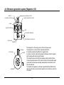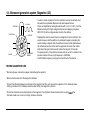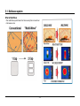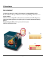
1
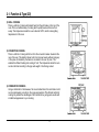
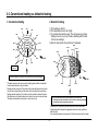
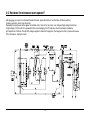
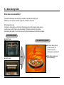
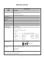
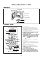
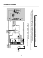
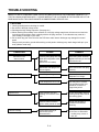
http://www.LGEservice.com
E-mail:[email protected]
MICROWAVE OVEN
SERVICE MANUAL
MODEL : MA-2005ST
CAUTION
BEFORE SERVICING THE UNIT, READ THE
SAFETY PRECAUTIONS IN THIS MANUAL.
SAFETY PRECAUTIONS
This device is to be serviced only by properly qualified service personnel.
Consult the service manual for proper service procedures to assure continued safety operation and for precautions to be
taken to avoid possible exposure to excessive microwave energy.
PRECAUTIONS TO BE OBSERVED BEFORE AND
DURING SERVICING TO AVOID POSSIBLE
EXPOSURE TO EXCESSIVE MICROWAVE ENERGY
A) Do not operate or allow the oven to be operated with the door open.
B) Make the following safety checks on all ovens to be serviced before activating the magnetron or other
microwave source, and make repairs as necessary; (1) interlock operation, (2) proper door closing, (3)
seal and sealing surfaces (arcing, wear, and other damage), (4) damage to or loosening of hinges and
latches, (5) evidence of dropping or abuse.
C) Before turning on microwave power for any service test or inspection within the microwave generating
compartments, check the magnetron, wave guide or transmission line, and cavity for proper alignment,
integrity, and connections.
D) Any defective or misadjusted components in the interlock, monitor, door seal, and microwave generation
and transmission systems shall be repaired, replaced, or adjusted by procedures described in this manual
before the oven is released to the owner.
E) A microwave leakage check should be performed on each oven prior to release to the owner.
CAUTION
MICROWAVE RADIATION
DO NOT BECOME EXPOSED TO RADIATION FROM THE MICROWAVE GENERATOR
OR OTHER PARTS CONDUCTING MICROWAVE ENERGY.
2-1. Function & Type (1/2)
1. How a Microwave Oven Works
The microwave oven is one of the great inventions of the 20th century - millions of homes in world have one. Microwave
ovens are popular because they cook food incredibly quickly. They are also extremely efficient in their use of electricity
because a microwave oven heats only the food - nothing else.
A microwave oven uses microwaves to heat food. Microwaves are radio waves. In the case of microwave ovens, the
commonly used radio wave frequency is roughly 2,500 megahertz (2.5 gigahertz). Radio waves in this frequency range have
an interesting property: they are absorbed by water, fats and sugars. When they are absorbed they are converted directly into
atomic motion - heat. Microwaves in this frequency range have another interesting property: they are not absorbed by most
plastics, glass or ceramics. Metal reflects microwaves, which is why metal pans do not work well in a microwave oven.
2. Type of Microwave Oven
1) MICROWAVE COOKING (solo model)
Using the energy of microwaves only, food is cooked quickly without altering its
colour and shape. Microwaves generated by a magnetron enter the oven and cook
the food evenly on a rotating turntable. Power control can be adjusted in 11 steps
which can enable a variety of goods to cook at a suitable power for the best
results.
-8-
2-1. Function & Type (2/2)
2) GRILL COOKING
This is a method of cooking with radiant heat from the grill heater on the top of the
oven. This is a traditional way of cooking which quickly seals and browns food
evenly. The temperature inside the oven is fixed at 180°C, which is ideal grilling
temperature for this oven.
3) CONVECTION COOKING
This is a method of cooking with hot air from the convection heater situated at the
rear of the oven. This method allows food to be browned evenly without losing any
of the juices. Air heated by the heater is circulated in the oven by a fan. This
enables the efficient heating and cooking of food. The temperature inside the oven
can be controlled according to the type and weight of food being cooked.
4) COMBINATION COOKING
Using a combination of microwaves, hot air and radiant heat, this solid state control
can cook alternately, according to the cycles programmed. This efficient method of
cooking fully utilizes the advantages of all three functions, giving quick results with
a traditional appearance to your cooking.
-9-
2-2. Installation & Utensils (1/2)
1. Installation
1. Unpack your oven and place it on a flat level surface.
2. Place your oven in the level location of tour choice with more
than 85cm height but make sure there is at least 30cm of space
on the top and 10cm at the rear for proper ventilation. The front
of the oven should be at least 8cm from edge of the surface to
prevent tipping. An exhaust outlet is located on top of side of the
oven. Blocking the outlet can damage your oven.
5. Fill a microwave safe container
with 300 ml (1/2 pint) of water.
Place on the GLASS TRAY and
close the oven door.
6. Press the START button six times to
set 3 minutes of cooking time. You
will hear a BEEP each time you
press the button. Your oven will start
before you have finished the sixth
press; don’t worry this is normal.
3. Plug your oven into a standard household socket. Make sure
your oven is the only appliance connected to the socket. If your
oven does not operate properly, unplug it from the electrical
socket and then plug it back in.
4. Open your oven door by pressing the DOOR HANDLE. Place
the ROLLER REST inside the oven and place the GLASS
TRAY on top.
7. The DISPLAY will count down from
3 minutes. When it reaches 0 it will
sound three BEEPS. Open the oven
door and test the temperature of the
water. If your oven is operating the
water should be warm. Be careful
when removing the container it
may be hot.
- 10 -
2-2. Installation & Utensils (2/2)
2.COOKING UTENSILS
Utensils should be checked to ensure that they are suitable for use
in the microwave oven.
The following chart summaries the proper use of cooking utensils
in your oven:
Cooking utensils
Heat resistant glass, glass ceramic
Ceramic, china
Metal cookware
Non-heat resistant glass
Microwave plastic
Plastic wrap
Paper (cup, plates, towels)
Straw, wicker and wood
Microwave
yes
yes
(Do not use china
with gold or
silver trim.)
no
no
yes
yes
yes
no
Grill
yes
yes
yes
no
no
no
no
no
3.Plastic dishes, cups, freezer bags, and plastic wraps may be
used in the microwave oven. Follow the manufacturer’s
instructions or the information given in the cookbook when
using plastics in the microwave oven.
4.Metal utensils and utensils with metallic trim should not be
used in the microwave oven.For more information on the
proper use of metal in your oven, please read the introduction
section in the cookbook. If the use of aluminum foil, skewers,
or utensils containing metal in the oven is specified in the
recipe, allow at least 2.5cm clearance between the metal
object and the interior oven wall. If arcing (sparks) occurs,
remove immediately.
Note:
Consult your cookbook, individual recipes, and charts for correct
use of cooking containers, products, and other useful information.
Microwave
1. Most glass, glass ceramic, and heat resistant glassware utensils
are excellent. Those with metal trim should not be used in a
microwave oven.
2. Paper napkins, towels, plates, cups, cartons, and cardboard can
be used in the microwave oven. Do not use recycled paper
products since they may contain impurities which may cause
sparks and/or fires when used in cooking. (Consult your
cookbook for correct use of these products.)
Grill
1. Heat resistant glassware, ceramic and metal cookware can
be used.
2.Paper napkins, towels, and plastics should not be used.
Note:
• Care should be taken when removing utensils or the glass
turntable, as they may become hot during cooking.
• Only use a thermometer that is designed or recommended for
use in the microwave oven.
• Ensure the turntable is in place when you operate the oven.
- 11 -
3-1. What’s the microwave? (1/2)
1. History of dielectric heating
In 1945, Dr. Spencer working for RAYTHEON Co. in the U.S.A found out a pieces of chocolate in his pocket melting suddenly by the
electric wave (ultra high frequency wave using for radar) on his experiment for radar. then began research in heating matters by the
electric wave.
So far, experiments for heating foods by the electric wave has been developed into the household telephone as well as microwave
oven, etc. The heating method for microwave is to give an electric wave to the food and make the food itself generate heat. It is
different from that of the past which was to give heat to the food and make the temperature rise.
So, since the microwave oven does not give any heat to the food, we do not need appliances like the gas oven.
Not only the microwave oven itself but utensil don’t get hot either, when heat is provided, the utensil will gradually got hot by thermal
conduction, however, the temperature of the surface and the inside of the fond get hot simultaneously and the food is well-done rapidly.
2. The principle of dielectric heating
The microwave oven has a vacuum tube called magnetron (M.G.T), it injects the electric wave of 2450MHz (The vibrations of two
billion four hundred and fifty million per second are given to the oven) This electric wave is called the microwave. The wireless electric
wave (having not more than 1 m of the wave length) is using for the radio telephone and broad casting of T.V. and radar (a radio locator).
It is similar to an electric wave and its wave length is short. (The length of the electric wave having frequency of 2450MHz is 12.2cm)
The characteristics of this microwave is as follows:
1. When it touches the metal, it is reflected and changed direction.
2. It passes through ceramics, porcelain (glass, etc), plastics, and paper.
3. If it is touches the food or the wood having water in humidity, it is absorbed and generates heat.
The Microwave oven cook food using these characteristics. Generally, the food, whether it is large or small has humidity. So if you put
this food in the microwave oven and it gets the electric wave, so the energy of it is absorbed in the food since it set up a vibration of
the molecules with a frequency two billion four hundred and fifty million times per second. The friction among molecules of food occurs
repeatedly. It then causes the frictional heat, and the temperature of the food rises.
- 12 -
3-1. What’s the microwave? (2/2)
3. The safety of microwave oven
Since the microwave oven can’t make the native fire like gas, you have no use for worrying about the fire.
Because it doesn’t become hot like the ordinary electric range. It has been used in the dinner car of the trains etc.
Microwave oven has the shielded structure strictly with metal case not to leak electric wave at once not only using but on opening
the door.
Because it uses the electric wave, the x-ray is never emitted. The UHF wave generally called microwave is like the electric wave of
the TV or the radio and is used for the wireless communication, the radar and the UHF medical instruments (using 2450 MHz like
that of the microwave oven, etc).
4. Definition of electric wave
* An electric wave is the electron wave of the frequency from 10 KHz to 3,000,000 MHz.
* Wave length of 2450 MHZ.
λ
c
f
300000 Km
245000 KHz
0.122 m
12.2 cm
λ: Wave Length
Where c: The Velocity of Light
f: Frequency
The division from the sound frequency to the light frequency.
FREQ
20 Hz
3 Hz
30 Hz 300 KHz 3 MHz 30 MHz 300 MHz 3 GHz 30 GHz 300 GHz
20 KHz 30 KHz 300 KHz 3 MKHz 30 MHz 300 MHz 3 GHz
30 GHz 300 GHz 1016 Hz
NAME
SOUND
WAVE
VLF
LF
MF
HF
VHF
ULF
SHF
EHF
USE
MUSIC
SHIP
RADIO
RADIO
RADIO
T.V
MWO
T.V
RADAR
RADAR
- 13 -
LIGHT
3-2. Conventional heating vs. dielectric heating
2. Dielectric heating
1. Conventional heating
FIRE!
FIRE!
HEAT
!
AT
HE
1) The heating is uniform.
2) The temperature rise is fast (high).
3) If you break the electric power: The microwave oven stops
heating at once, so you can’t heat something with the heat
of their surroundings.
4) Since it heats inside, the surface isn’t damaged.
FIRE!
FIRE!
!
HEAT!
FIRE!
HEAT!
HE
AT
!
AT
!
WELL-DONE!
HE
HALF-DONE!
!
AT
HE
UNDER!
DONE!
HE
HE
AT
!
FIRE!
AT
FIRE!
FIRE!
WAVE
WAVE
WAVE
FIRE!
!
WAVE
HE
AT
FIRE!
!
AT
HEAT
FIRE!
!
WAVE
WAVE
HE
!
HEAT!
HEAT
!
FIRE!
MOLECULES
FOOD!
WAVE
FIRE!
FIRE!
TRANSMITTED!
BY CONDUCTION!
WAVE
WAVE
It shall be heated by the sources of the electric heater, the gas, and the briquet.!
WAVE
* The heat energy from the sources of the heating power shall be transmitted
from the warm surface to the cold inside.
* Heating with the strong fire: The surface of the food shall be well done, but be
burnt to have a black side, and the center of the food shall not be well-done.
* Heating with the weak fire: The surface of the food shall be burnt and have a
little black side, but it shall be taken lots of time for the center to be well-done.
* The thermal conductivity in the water or in the food is low.
WAVE
FOOD
WAVE
WAVE
• If you give microwave to food with the microwave oven, the food and
molecules of the water included in the food is turned, or moved and generates
heat with the friction among the the molecules.
* The water, the oil and the foods shall absorb the electric wave well.
* It generates heat all around the apparatus and the foods are well-done
with short time
* If you heat something for long time, all of it will be burnt and can’t be eaten.
- 14 -
4-1. Construction of microwave oven
Cavity
Cabinet locking
in microwave
and holding
food.
Door
Gate coming in
and out food.
It has window
and seal
structure
Magnetron
Inject microwave
to oven.
OVEN CAVITY PARTS
Controller
Control and
supervise
operating state
of oven.
INTERIOR PARTS
BASE PLATE PARTS
DOOR PARTS
LATCH BOARD PARTS
CONTROL PANEL PARTS
- 15 -
4-2. How does the microwave oven operate?
After plugging your oven into a standard household socket, press start button or turn the timer. And then switches
(primary, secondary, timer) close the circuit.
Eventually the input power will be applied to turntable motor, timer motor, fan motor, oven lamp and high voltage transformer.
A high voltage of 2,100 volts AC is generated in the second winging of H.V.Transformer. And the voltage is doubled by
H.V.Capacitor & H.V.Diode. The 4Kv DC voltage is applied to filament of magnetron, then magnetron start to produce microwave.
This microwave is injected to cavity.
- 16 -
4-3. WARNING - High voltage circuit ( 4,000 volt )
+
INPUT
* The half-wave voltage doubler circuit consists of the secondary winding of
the high voltage transformer, H.V. diode (rectifier), and H.V. capacitor. The
H.V. diode allows alternating current (AC) to flow in one direction only and
rectifies it to pulsating direct current (DC).
The H.V. capacitor is able to store energy on one half of the AC cycle and
release it on the other half cycle.
-
+
MAGNETRON
SENONDARY
WINDING AT
2000V
-
+
INPUT
-
* During the second half cycle of operation, the current flows in the opposite
direction, again supplies 2000 Volts to the circuit.
-
MAGNETRON
SECONDARY
WINDING AT
2000V
+
* During the first half cycle of operation, the secondary winding of the
transformer supplies 2000 Volts to the capacitor current flows through the
diode and returns to the transformer for a complete circuit. This half-cycle
of AC charges the capacitor to approximately 2000 Volts.
* This permits the capacitor to discharge its 2000 Volts on top of the 2000
Volts generated by the secondary winding, creating an approximate total
voltage of negative 4000 Volts D.C.
The negative 4000 Volts DC causes the magnetron to conduct current
and, to oscillate at 2450 MHz.
The first half cycle and the second half cycle become one complete cycle,
repeated input power frequency times per second .
- 17 -
4-4. Microwave generation system_Magnetron (1/2)
GASKET
ANTENNA (OUTPUT)
FILAMENT (CATHODE)
MAGNET (MAGNETIC CIRCUIT)
ANODE
MAGNET (FERRITE)
VANE
FILAMENT TERMINALS
FEED THROUGH CAPACITOR
FILTER CASE
FILTER
ANTENNA
ELECTRONS
ANODE
CATHODE
* The magnetron is the energy source for the microwave oven.
The magnetron is a vacuum tube of special construction.
It is basically a diode with addition of a magnetic field.
It consists of a small, coiled heating element (filament) made of tungsten
which readily emits electrons when heated.
This element serves as the cathode (negative element) within the tube.
The anode (positive element of the tube) consists of a thick walled copper
cylinder with vertical vanes extending inward which surround but do not
touch the cathode.
To complete the magnetron, and make it operate distinctly different from
other vacuum tubes, two permanent magnets are mounted over each end
of the tube.
- 18 -
4-4. Microwave generation system_Magnetron (2/2)
2,450 MHz.
ANTENNA
ELECTRONS
ANODE
* In order to create an electron flow from cathode to anode, the cathode must
be heated and a potential difference must exist between the two.
This is accomplished by heating the cathode with 3, 4 to 3,5 V AC. ( from the
filament winding of the high voltage transformer) and applying a negative
4000 V DC (from the voltage doubler circuit) to the cathode.
CATHODE
PERMANENT
MAGNET
* Originally the electrons would travel in a straight line from the cathode to the
anode. However, with the addition of a permanent magnet surrounding the
anode creating a magnetic field, the electrons travel an orbital path between
the cathode and anode. As the electrons approach the anode, their orbital
path takes them past small resonant cavities that are part of the anode.
The passing notion of the electrons induces electron current to oscillate in the
resonant cavities at the very high frequency or 2,450 MHz.
This RF (Radio frequency) energy is then transferred to the antenna.
TESTING MAGNETRON TUBE
* Disconnect power, remove the wrapper, and discharge the capacitor.
* Remove the two leads from the magnetron terminals.
* Connect the ohmmeter between one terminal of the magnetron and the outer case of the magnetron. If the ohmmeter reads
infinity, go to below. If the ohmmeter reads less than infinity, the magnetron is shorted.
* Connect an ohmmeter across the terminals of the magnetron. The ohmmeter should read less than one ohm
ohmmeter reads over one ohm or infinity, the tube is defective.
- 19 -
f the
5-1. Multiwave system
What is Multi-Wave
• The multi-Wave system heats food more evenly than convectional
microwave ovens.
- 20 -
5-2. Infrared sensor
What’s the infrared sensor?
You may be annoyed when you defrost or reheat food with microwave oven. If you reheat soup, the result is superficial.
The surface is hot but inside of the soup is still cold. You have to set the clock and push “Start” again. The cooking time is much
longer than you expected.
LG microwave oven reduce cooking time. Our revolutionary Infrared sensor makes it 3 times faster than the ordinary microwave.
Infrared eye tracks the exact temperature of food and regulates the power of the microwave so that the temperature reaches you
actually set.
We prepared the temperature LED bar and dial for your precise control and convenience.
Infrared sensor means fast and real hot result.
Power
Output
Finish
Time
Finish
Save 40%
Off
- 21 -
5-3. Auto moving heater
What’s does move automatically?
Conventional microwave oven with grill has a heater on the ceiling of cooking room.
Whether you cook a pizza or chicken, the position of heater is unmovable.
We changed the old way.
LG heater is moving when you choose grill, the heater goes down. The angle of heater varies as
to each menu. You don’t have to worry about safety. The heater moves back to it’s position
automatically after grilling. Your food is more evenly grilled and delicious when Auto Moving Heater.
Conventional Heater
"Sheath Heater
LG’s Auto Moving Heater
"One-touch Grilling & Oven
- Cookie ‘ Heater 45°
- Pizza,Frozen pizza,
Chicken piece ‘ Heater 90°
"Quartz Heater
"When grilling, heater goes
down automatically.
R&D
- 22 -
SPECIFICATIONS
ITEM
MODEL
Power Requirement
DESCRIPTION
MA-2005ST
120 Volts AC 60 Hz
1,550 Watts (13.6 A)
Single phase, 3 wire grounded
Power Output
1,150 Watts full microwave power (IEC705)
Microwave Frequency
2,450 MHz
Magnetron
2M246, 2M248J
Timer
0 ~ 99 min. 99 sec.
Outside Dimensions
237/8” (W) x 139/16” (H) x 1813/16” (D)
Cavity Dimensions
171/16” (W) x1013/16” (H) x 185/16” (D)
Net Weight
42 lbs (approx.)
Shipping weight
46 lbs (approx.)
Control Complement
Touch Control System
Clock : 1:00 - 12:59
Microwave Power for Variable Cooking
Power level
HIGH ----------------------------------------Full power throughout the cooking time
9 (Saute) -------------------------approx. 90% of Full power,
8 (Reheat) --------approx. 80%
7 (Med.-High) --------------------approx. 70%,
6 (Medium) --------approx. 60%
5 (Med.-Low) --------------------approx. 50%,
4 (Defrost) ---------approx. 40%
3 (Low) ---------------------------approx. 30%,
2 (Simmer)--------approx. 20%
1 (Warm)--------------------------approx. 10%
Nameplate Location
Back Side
Accessories
Owner's manual & cooking guide
Glass turntable
Rotating ring
This microwave oven is designed for household use only.
It is not recommended for commercial purposes.
1-1
OPERATING INSTRUCTIONS
FEATURES
Oven Front Plate
Window Door Screen
Door Seal
Display Window
Control Panel
Door Open Button
Safety Door Lock System
Turntable
Rotating Ring
CONTROL PANEL
1. DISPLAY WINDOW.
2. ONE TOUCH CONTROL: This menu has been pre
programmed to cook food automatically by one touch.
3. AUTO DEFROST: This feature provides you with the best
defrosting method for frozen foods.
4. CUSTOM COOK: This feature allows you to set and execute
a frequently used single stage program.
5. NUMBER: These used to set for time of day, cooking time,
power level, or defrost weight.
6. MORE / LESS: All of the one touch cook and TIMED COOK
can be adjusted to cook food for a longer or shorter time.
MORE
Pressing MORE will add 10 seconds to the
cooking time.
LESS
Pressing LESS will subtract 10 seconds of
cooking time.
7. STOP/CLEAR: It used to stop oven and clear all entries
except time of day.
8. CUSTOM SET: You can select sound on/off, clock on/off,
scroll speed, lbs/kg choice, language choice, demo on/off
mode.
9. TIME: You can set the desired cook time.
10. POWER: You can select the desired power level for
cooking.
11. TIMER: You can use the timer function of your oven for
purpose other than cooking.
12. CLOCK: It is used to set the time of day.
13. EZ ON: You can extend cooking time in multiples of
1 minute by repeatedly touching this pad during cooking.
14. START: This feature allows oven to begin functioning.
1150W
1
2
3
8
4
9
5
10
11
6
12
7
13
14
4-1
OPERATING SEQUENCE
7. AUTO DEFROST COOKING
The following is a description of component functions
during oven operation.
STOP/CLEAR
1. SETTING THE CLOCK
NUMBER OF
WEIGHT
AUTO
DEFROST
START
8. CHILD LOCK
STOP/CLEAR
CLOCK
NUMBER
CLOCK
This oven has a CHILD LOCK feature
TO SET CHILD LOCK
¥ Touch and hold 0 pad
LOCKED appears on
the display.
ex.) To set 4:30, touch number key [4],[3], and [0].
NOTE: 1) This is a 12 hour clock.
2) Clock will operate as long as power is
applied to the oven.
TO CANCEL CHILD LOCK
¥ Touch and hold 0 pad
disappears.
2. CANCEL FUNCTION
Touch the STOP/CLEAR pad whenever you need to
cancel an entry or a function currently in use.
The display will return either to the last item entered
or to the clock.
9. MORE / LESS
The cook time is adjustable by MORE pad or LESS
pad
3. EZ ON
STOP/CLEAR
EZ on
COOKING
MORE
STOP/CLEAR
COOKING
LESS
You can program the cook time and power level by
using CUSTOM COOK pad.
ex) To set cook time 10 mine 30seconds, touch
number key [1],[0],[3], and [0]
POPCORN
NOTE: Heat only 1 package at a time
5. TIME COOKING
STOP/CLEAR
STOP/CLEAR
10. CUSTOM COOK
4. ONE TOUCH COOKING
STOP/CLEAR
STOP/CLEAR
TIME
NUMBER
NUMBER
START
LOCKED
POWER
CUSTOM
COOK
NUMBER
NUMBER
START
POWER
11. CUSTOM SET
You can select Sound On/Off, Clock On/Off, Scroll
Speed, Lbs/Kg Choice, Demo On/Off modes.
6. MULTI-STAGE COOKING
¥ To turn ON/OFF sound.
1ST STAGE
STOP/CLEAR
TIME
NUMBER
STOP/CLEAR
POWER
CUSTOM
SET
NUMBER
NUMBER
START
NUMBER
NUMBER
START
¥ To select scroll speed
NUMBER
STOP/CLEAR
2ND STAGE
TIME
NUMBER
NUMBER
START
POWER
4-2
CUSTOM
SET
N
L
4-3
WH
CN1
8
7
6
5
RY2
PK
GN
RY1
** NOTE : DOOR IS OPENED.
BL
4
3
2
1
PT1
MICOM
CONTROLLER
BK
BK : BLACK
WH : WHITE
SECONDARY
SWITCH
GN
O.L.
WH
YL
WH
BK
MONITOR
SWITCH
RD : RED
BN : BROWN
T.T.M.
TURN
TABLE
MOTOR
RD
FAN
MO TOR
YL : YELLOW
GN : GREEN
WH
F.M.
RD
OVEN
LAMP
BL : BLUE
PK : PINK
WH
BK
BK
PRIMARY
SWITCH
BN
RD
H.V.
TRANSFORMER
H.V. DIODE
H.V.
CAPACITOR
MAGNETRON
NOTICE: SINCE THIS IS BASIC SCHEMATIC DIAGRAM, THE VALUES OF COMPONENTS AND
SOME PARTIAL CONNECTIONS ARE SUBJECT TO CHANGE FOR IMPROVEMENT.
IMPORTANT SAFETY NOTE: THE SHADED AREAS ON THIS SCHEMATIC DIAGRAM INCORPORATE SPECIAL FEATURES
IMPORTANT FOR PROTECTION FROM MICROWAVE RADIATION, FIRE, ELECTRICAL SHOCK, AND
HAZARDS. WHEN SERVICING IT IS ESSENTIAL THAT ONLY MANUFACTURER'S SPECIFIED PARTS
BE USED FOR THE CRITICAL COMPONENTS IN THE SHADED AREAS OF THE SCHEMATIC DIAGRAM.
AC 120V
60Hz
GN
FUSE
20A
SCHEMATIC DIAGRAM
CIRCUIT DESCRIPTION
¥ A high voltage of approximately 2100 volts AC is
generated in the secondary of the high voltage
transformer which is increased by the action of the high
voltage diode and charging of the high voltage
capacitor.
¥ The negative 4,000 Volts DC is applied to the filament
of the magnetron.
GENERAL DETAILS
¥ The low voltage transformer supplies the necessary
voltage to the micom controller when power cord is
plugged in.
¥ When the door is closed, the primary switch is ON, the
secondary switch is ON, and the monitor switch opens
(contact COM and NO).
WHEN THE OVEN IS SET AT ANY LEVEL
EXCEPT MAXIMUM.
WHEN SELECTING COOKING POWER
LEVEL AND TIME
¥ The micom controller controls the ON-OFF time of
relay 2 by the applied signal to vary the average output
power of microwave oven as POWER LEVEL.
(refer to page 1-1)
¥ One complete cycle of relay 2 is 22 seconds.
¥ The micom controller memorizes the function you set.
¥ The time you set appears in the display window.
¥ Each indicator light turns on to indicate that the stage
has been set.
WHEN TOUCHING THE START PAD
WHEN THE DOOR IS OPENED DURING
COOKING
¥ The coil of the relay is energized by the micom
controller.
¥ Power input is supplied to the high voltage transformer
through the fuse to the primary switch and relay 2.
¥ Turntable rotates.
FUSE
¥ Both the primary switch and relay 2 cut off the primary
winding voltage of the high voltage transformer.
¥ ON-OFF of relay 2 is coupled electrically with opening
and closing of the secondary switch.
¥ When the door is opened, the secondary switch is
opened and when the door is closed, the secondary
switch is closed.
¥ The cooking time stops counting down.
¥ Relay stops functioning.
¥ As the door is opened, if the contact of primary switch
and relay2 and/or secondary switch fail to open, the
fuse opens due to the large current surge caused by
the monitor switch activation, which in turn stops
magnetron oscillation.
PRIMARY
SWITCH
L
MONITOR
SWITCH
N
RELAY 2
H.V.
TRANSFORMER
FUSE
SECONDARY
SWITCH
PRIMARY
SWITCH
L
MICOM CONTROLLER
H.V.
TRANSFORMER
MONITOR
SWITCH
¥ The fan motor rotates and cools the magnetron by
blowing the air (coming from the intake on the baseplate).
¥ The air is also directed into the oven to exhaust the
vapor in the oven through the upper plate.
¥ Cooking time starts counting down.
¥ 3.3 volts AC is generated from the filament winding of
the high voltage transformer. This 3.3 volts is applied to
the magnetron to heat the magnetron filament through
two noise-preventing choke coils.
N
RELAY 2
SECONDARY
SWITCH
MICOM CONTROLLER
4-4
SERVICE INFORMATION
TOOLS AND MEASURING INSTRUMENTS
NECESSARY TOOLS
NECESSARY MEASURING INSTRUMENTS
Tools normally used for TV servicing are sufficient.
Standard tools are listed below.
¥ Diagonal pliers
¥ Long nose pliers
¥ Phillips screwdriver
¥ Flat blade screwdriver
¥ Wrench (size 5mm)
¥ Nutdriver (size 5mm)
¥ Adjustable wrench
¥ Soldering iron
¥ Solder
¥ Vinyl insulation tape
¥ Polishing cloth
¥ TESTER (VOLTS-DC, AC, Ohmmeter)
¥ Microwave survey meter
- Holaday HI-1500
HI-1501
- Narda 8100
8200
¥ Inch scale
¥ 600 cc non conductive material beaker (glass or plastic),
inside diameter: approx. 8.5 cm (31/2 in.)
¥ Cylindrical and made of borosilicate glass vessel.
max. thickness: 3 mm
outside diameter: approx. 190mm
height: approx. 90mm
¥ Glass thermometer: 100¡C or 212¡F (1 deg scale)
MICROWAVE LEAKAGE TEST
CAUTIONS
MEASURING MICROWAVE ENERGY
LEAKAGE
¥ Be sure to check microwave leakage prior to
servicing the oven if the oven is operative prior to
servicing.
¥ The service personnel should inform the
manufacture importer, or assembler of any certified
oven unit found to have a microwave emission
level in excess of 5 mW/cm2 and should repair any
unit found to have excessive emission levels at no cost
to the owner and should ascertain the cause of the
excessive leakage. The service personnel should
instruct the owner not to use the unit until the oven has
been brought into compliance.
¥ If the oven operates with the door open, the service
personnel should:
- Tell the user not to operate the oven.
- Contact the manufacturer and CDRH
(Center for Devices and Radiological Health)
immediately.
NOTE: Address on CDRH
Office of Compliance(HFZ-312)
Center for Devices and Radiological
Healthe 1390, Piccard Drive,
Rockville. MD 20850
¥ The service personnel should check all surface and
vent openings for microwave leakage.
¥ Check for microwave leakage after every servicing. The
power density of the microwave radiation leakage
emitted by the microwave oven should not exceed
4 mW/cm2. Always start measuring of an unknown field
to assure safety for operating personnel from radiation
leakage.
¥ Pour 275±15cc of 20±5¡C(68±9¡F) water in a beaker
which is graduated to 600 cc, and place the beaker
on the center of the turntable.
¥ Set the energy leakage monitor to 2,450 MHz and
use it following the manufacturer's recommended
test procedure to assure correct result.
¥ When measuring the leakage, always use the 2-inch
(5cm) spacer supplied with the probe.
¥ Operate the oven at its maximum output.
¥ Measure the microwave radiation using and
electromagnetic radiation monitor by holding the
probe perpendicular to the surface being measured
Move probe along shaded area
Probe scanning speed
Less than 2.5 cm/sec
( 1in/sec)
5-1
MEASUREMENT WITH OUTER CASE
REMOVED
NOTES WHEN MEASURING
¥ Do not exceed meter full scale deflection.
¥ The test probe must be removed no faster than
1 inch/sec (2.5 cm/sec) along the shaded area,
otherwise a false reading may result.
¥ The test probe must be held with the grip portion of the
handle.
A false reading may result if the operator's hand is
between the handle and the probe.
¥ When testing near a corner of the door, keep the probe
perpendicular to the surface making sure the probe
horizontally along the oven surface; this may possibly
cause probe damage.
¥ When you replace the magnetron, measure for
microwave energy leakage before the outer case is
installed and after all necessary components are
replaced or adjusted.
Special care should be taken in measuring the
following parts. (Circled area of Fig. below)
- Around the magnetron
- The waveguide
WARNING : AVOID CONTACTING ANY
HIGH VOLTAGE PARTS
RECORD KEEPING AND NOTIFICATION
AFTER MEASUREMENT
¥ After adjustment and repair of any microwave energy
interruption or microwave energy blocking device,
record the measured values for future reference. Also
enter the information on the service invoice.
¥ The microwave energy leakage should not be more
than 4 mW/cm.sq. after determining that all parts are in
good condition, functioning properly and genuine
replacement parts which are listed in this manual have
been used.
¥ At least once a year, have the electromagnetic energy
leakage monitor checked for calibration by its
manufacturer.
SPECIAL TIP
¥ This oven used the button head screws.
MEASUREMENT WITH A FULLY
ASSEMBLED OVEN
¥ After all components, including the outer case, are fully
assembled, measure for microwave energy leakage
around the door viewing window, the exhaust opening,
and air inlet openings.
¥ Microwave energy leakage must not exceed the values
prescribed below.
Button Head
(Torx style 2)
¥ When you remove the screws, use the
tamper-resistant Torx driver having a
pin-in-head.
NOTE: Leakage with the outer case removed less than
5 mW/cm.sq. Leakage for a fully assembled
oven (Before the latch switch (primary) is
interrupted) with the door in a slightly opened
position-less than 2 mW/cm.sq.
5-2
MEASUREMENT OF MICROWAVE POWER OUTPUT
¥ Microwave power output measurement is made with
the microwave oven supplied at its rated voltage and
operated at its maximum microwave power setting with
a load of (1000±5) g of potable water.
¥ The water is contained in a cylindrical borosilicate glass
vessel having a maximum material thickness of 3 mm
and an outside diameter of approximately 190mm.
¥ The oven and the empty vessel are at ambient
temperature prior to the start of the test.
¥ The initial temperature (T1) of the water is (10±2)¡C It
is measured immediately before the water is added to
the vessel. After addition of the water to the vessel,
the load is immediately placed on the center of the
turntable which is in the lowest position and the
microwave power switched on.
¥ The time T for the temperature of the water to rise by a
value Æ T of (10±2)¡K is measured, where T is the time
in seconds and ÆT is the temperature rise. The initial
and final water temperatures are selected so that the
maximum difference between the final water
temperature and the ambient temperature is 5¡K.
¥ The microwave power output P in watts is calculated
from the following formula :
P=
4187 x (ÆT)
T
is measured while the microwave generator is
operating at full power. Magnetron filament heat-up
time is not included. (about 3 sec)
¥ The water is stirred to equalize temperature throughout
the vessel, prior to measuring the final water
temperature.
¥ Stirring devices and measuring instruments are
selected in order to minimize addition or removal of
heat.
WATER LOAD
TURNTABLE
DISASSEMBLY AND ADJUSTMENT
A. OUTER CASE REMOVAL
Remove the screw
1) Disconnect the power supply cord from the outlet.
2) Remove the screws from the rear of the case.
The outer case must be moved backward to be lifted
off.
B. POWER SUPPLY CORD
1) Remove the outer case.
2) Disconnect two terminals, and remove one screw of
the ground terminal.
ground screw
C. CONTROL PANEL ASSEMBLY
1) Open the door.
2) Disconnect the leadwire from RELAY (RY2) of the
PCB SUB ASSÕY.
3) Disconnect the leadwire from connector (CN1) of the
PCB SUB ASSÕY.
4) Lift up and pull out control panel assembly carefully
from the cavity.
Lift up and pull out control panel
CAUTION: DISCHARGE THE HIGH VOLTAGE
CAPACITOR BEFORE SERVICING
(refer to page 2-1)
5-3
D. PCB ASSEMBLY REMOVAL
Remove choke cover
1) Remove the control panel assembly from the
cavity. (Refer to control panel assembly removal
on previous page.)
2) Remove screws which hold the PCB SUB ASSÕY to
the control panel.
3) Disconnect the flat cable from the PCB SUB
ASSÕY and take off the PCB SUB ASSÕY
Control Panel
PCB Sub Asm
Key Membrane
Remove door
Button Spring
Door Open Button Release
Lever
E. DOOR MAIN ASSEMBLY REMOVAL
1) Open the door.
2) Remove the choke cover very carefully with a flat-blade
screwdriver.
CAUTION: Be careful not to damage door seal plate
by screwdriver.
3) Lift up and push the door.
Spacer
NOTE:
1. After replacing the door, be sure to check that the
primary switch, monitor switch, and secondary switch
operate normally.
2. After replacing the door, check for microwave energy
leakage with a survey meter. Microwave energy must
be below the limit of 4 mW/cm. (with a 275 ml water
load)
3. When mounting the door assembly to the oven
assembly, be sure to adjust the door assembly parallel
to the chassis. Also adjust so the door has no play
between the inner door surface and oven frame
assembly. If the door assembly is not mounted
properly, microwaves may leak from the clearance
between the door and the oven.
5-4
F. AIR DUCT ASSEMBLY REMOVAL
H. REMOVING THE TURNTABLE MOTOR
1) Remove the turntable and rotating ring.
2) Lay the unit down on its back.
3) Remove the turntable motor cover.
The turntable base cover is easily removed by
pinching the eight parts with a wire cutting.
4) Disconnect the leadwire from the turntable motor
terminals.
5) Remove the screw securing the turntable motor to
the oven cavity ASSÕY
6) After repairing the motor, rotate the removed
turntable motor cover.
7) Fit the turntable motor coverÕs projecting part to the
base plate slit.
1) Disconnect the leadwire from the lamp.
2) Remove the mounting screw to the magnetron.
G. MAGNETRON REMOVAL
1) Disconnect the leadwire from the magnetron.
2) Carefully remove the mounting screws holding the
magnetron and the waveguide.
3) Remove the magnetron ASSÕY until the tube is
clear from the waveguide.
NOTE:
1. When removing the magnetron, make sure its
dome does not hit any adjacent parts, or it may be
damaged.
2. When replacing the magnetron, be sure to install
the magnetron gasket in the correct position and
be sure that the gasket is in good condition.
3. After replacing the magnetron, check for microwave
leakage with a survey meter around the
magnetron. Microwave energy must be below the
limit of 5 mW/cm2. (With a 275 ml. water load).
Make sure that gasket is rigidly attached to the
magnetron. To prevent microwave leakage,
tighten the mounting screws properly, making sure
there is no gap between the waveguide and the
magnetron.
NOTE:
1. Remove the wire lead from the turntable motor
VERY CAREFULLY.
2. Be sure to grasp the connector, not the wires, when
removing.
Air Duct
Magnetron
Waveguide
Wire Leads
Dome
Waveguide
Bracket
Magnetron
Gasket
Magnetron
Turntable Motor
5-5
I. HIGH VOLTAGE TRANSFORMER
REMOVAL
L. INTERLOCK SYSTEM
1) INTERLOCK MECHANISM
The door lock mechanism is a device which has
been specially designed to eliminate completely
microwave activity when the door is opened during
cooking and thus to prevent the danger resulting
from the microwave leakage.
1) Discharge the high voltage capacitor.
2) Disconnect the leadwire from magnetron, high voltage
transformer, and capacitor.
3) Remove the screw holding the high voltage
transformer to the baseplate.
J. FAN MOTOR ASSEMBLY REMOVAL
ADJUSTMENT
DIRECTION
1) Discharge the high voltage capacitor.
2) Disconnect the leadwire from fan motor and high
voltage capacitor.
3) Remove the two screws holding the the suction guide
ASSÕY to the oven cavity and remove the high voltage
diode earth screw.
4) Remove the two screws holding the fan motor ASSÕY
to the suction guide ASSÕY.
SECONDARY
SWITCH
MONITOR
SWITCH
K. HIGH VOLTAGE CAPACITOR AND
DIODE REMOVAL
1) Discharge the high voltage capacitor.
2) Disconnect the leadwire from fan motor and high
voltage capacitor.
3) Remove the screw holding the suction guide ASSÕY to
the oven cavity and remove the high voltage diode
earth screw.
4) Remove the screw holding the high voltage capacitor
bracket.
PRIMARY
SWITCH
2) MOUNTING OF THE PRIMARY/MONITOR/
SECONDARY SWITCHES TO THE LATCH
BOARD
3) INSTALLATION AND ADJUSTMENT OF THE
LATCH BOARD TO THE OVEN ASSEMBLY
¥ Mount the latch board to the oven assembly.
¥ Adjust the latch board in the arrow direction so that
oven door will not have any play in it when the door
is closed.
¥ Tighten the mounting screw.
¥ Check for play in the door by pushing the door
release button. Door movement should be less
than 0.5 mm. (1/64 inch)
Don't push the door release button while making this
adjustment. Make sure that the latch moves
smoothly after adjustment is completed and that the
screws are tight. Make sure the primary, monitor,
and secondary switches operate properly by
following the continuity test procedure.
Fan Motor ASS'Y
Suction
Guide
H.V.
Capacitor
H.V.
Transformer
H.V.
Diode
5-6
INTERLOCK CONTINUITY TEST
WARNING : FOR CONTINUED PROTECTION AGAINST EXCESSIVE RADIATION
EMISSION, REPLACE ONLY WITH IDENTICAL REPLACEMENT PARTS.
TYPE NO. SZM-V 16-FA-63 OR VP-533A-OF FOR PRIMARY SWITCH
TYPE NO. SZM-V 16-FA-62 OR VP-532A-OF FOR MONITOR SWITCH
TYPE NO. SZM-V 16-FA-63 OR VP-533A-OF FOR SECONDARY SWITCH
B. SECONDARY INTERLOCK SWITCH TEST
A. PRIMARY INTERLOCK SWITCH TEST
Disconnect the wire lead from the secondary
switch.
Connect the ohmmeter leads to the common
(COM) and normally open (NO) terminals of the
switch. The meter should indicate a open circuit in
the door open condition. When the door is closed,
meter should indicate an closed circuit. When the
secondary switch operation is abnormal, make the
necessary adjustment or replace the switch only
with the same type of switch.
When the door release button is depressed slowly
with the door closed, an audible click should be
heard at the same time or successively at
intervals. When the button is released slowly, the
latches should activate the switches with an
audible click.
If the latches do not activate the switches when
the door is closed, the switches should be a
adjusted in accordance with the adjustment
procedure. Disconnect the wire lead from the
primary switch. Connect the ohmmeter leads to
the common (COM) and normally open (NO)
terminal of the switch. The meter should indicate
an open circuit in the door open condition.
When the door is closed, the meter should
indicate a closed circuit.
When the primary switch operation is abnormal,
make the necessary adjustment or replace the
switch only with the same type of switch.
COMPONENTS
SWITCHES
(Wire leads removed)
C. MONITOR SWITCH TEST
Disconnect the wire lead from the monitor switch.
Connect the ohmmeter leads to the common
(COM) and normally closed (NC) terminals of the
switch. The meter should indicate closed circuit in
the door open condition. When the door is closed,
meter should indicate an open circuit. When the
monitor switch operation is abnormal, replace with
the same type of switch.
NOTE: After repairing the door or the interlock
system, it is necessary to do this continuity
test before operating the oven.
TEST PROCEDURE
Check for continuity of the
switch with an Ohm-meter
Primary
Switch
Monitor
Switch
RESULTS
Door
open
Door
closed
NO
COM
NC
COM
Secondary
Switch
NO
COM
NOTE : After checking for the continuity of switches, make sure that they are
connected correctly.
5-7
COMPONENT TEST PROCEDURE
CAUTIONS
1. DISCONNECT THE POWER SUPPLY CORD FROM THE OUTLET WHENEVER REMOVING THE
OUTER CASE FROM THE UNIT. PROCEED WITH THE TEST ONLY AFTER DISCHARGING THE HIGH
VOLTAGE CAPACITOR AND REMOVING THE WIRE LEADS FROM THE PRIMARY WINDING OF THE
HIGH VOLTAGE TRANSFORMER. (SEE PAGE 2-1)
2. ALL OPERATIONAL CHECKS WITH MICROWAVE ENERGY MUST BE DONE WITH A LOAD (1 LITER
OF WATER IN CONTAINER) IN THE OVEN.
COMPONENTS
TEST PROCEDURE
RESULTS
HIGH VOLTAGE
TRANSFORMER
(Wire leads removed)
FILAMENT
WINDING
SECONDARY
PRIMARY
TERMINAL
1. Measure the resistance.
(Ohm-meter scale: Rx1 and Rx100)
¥ Primary winding
¥ Secondary winding
¥ Filament winding
Approx.: 0.2 ~ 0.4 ohm
Approx.: 60 ~ 90 ohm
Less than: 1 ohm
2. Measure the resistance.
(Ohm-meter scale: Rx1000)
¥ Primary winding to ground
¥ Filament winding to ground
Normal: Infinite
Normal: Infinite
MAGNETRON
(Wire leads removed)
1. Measure the resistance.
(Ohm-meter scale: Rx1)
¥ Filament terminal
Normal: Less than 1 ohm
2. Measure the resistance.
(Ohm-meter scale: Rx1000)
¥ Filament to chassis
Normal: Infinite
5-8
COMPONENTS
TEST PROCEDURE
RESULTS
Antenna
Gasket
Chassis
Filament
NOTE: When testing the magnetron, be sure to install the magnetron gasket
in the correct position and be sure that the gasket is in good condition.
HIGH VOLTAGE
CAPACITOR
HIGH VOLTAGE
DIODE
NOTE :
Some inexpensive meters
may indicate infinite
resistance in both direction.
Measure the resistance.
(Ohm-meter scale: Rx1000)
¥ Terminal to terminal.
Normal: Momentarily indicates
several ohms, and
then gradually returns
to infinite.
Measure the resistance.
(Ohm-meter scale: Rx1000)
¥ Terminal to case.
Normal: Infinite.
Measure the continuity (Forward).
(Ohm-meter scale: Rx10000)
Normal: Continuity.
Abnormal: Infinite.
Measure the continuity (Reverse).
(Ohm-meter scale: Rx10000)
Normal: Infinite.
Abnormal: Continuity.
5-9
COMPONENTS
RELAY 2
TEST PROCEDURE
RESULTS
Check for continuity of relay 2 with an
ohm-meter.
(Remove wire leads from relay 2 and
operate the unit.)
POWER
LEVEL
1
2
3
4
5
6
7
8
9
10
4 sec
6 sec
8 sec
10 sec
12 sec
14 sec
16 sec
18 sec
20 sec
22 sec
18 sec
16 sec
14 sec
12 sec
10 sec
8 sec
6 sec
4 sec
2 sec
0 sec
Relay 2
FAN MOTOR
(Wire leads removed)
Measure the resistance.
(Ohm-meter scale: R x 1)
Normal:
A: Approx. 85 ~ 100 ohm.
B: Approx. 10 ~ 25 ohm.
Abnormal: Infinite or several
ohm.
B
A
TURNTABLE
MOTOR
(Wire leads removed)
Measure the resistance.
(Ohm-meter scale: R x 1 )
Normal: Approx.100~150 ohm
Abnormal: Infinite or several
ohm.
NOTE : ¥ A MICROWAVE LEAKAGE TEST MUST ALWAYS BE PERFORMED WHEN THE UNIT IS
SERVICED FOR ANY REASON.
¥ MAKE SURE THE WIRE LEADS ARE IN THE CORRECT POSITION.
¥ WHEN REMOVING THE WIRE LEADS FROM THE PARTS, BE SURE TO GRASP THE
CONNECTOR, NOT THE WIRES.
5-10
TROUBLE SHOOTING
WHEN YOU GET A COMPLAINT FROM YOUR CUSTOMER, EVALUATE THE COMPLAINT CAREFULLY. IF
THE FOLLOWING SYMPTOMS APPLY, PLEASE INSTRUCT THE CUSTOMER IN THE PROPER USE OF THE
MICROWAVE OVEN. THIS CAN ELIMINATE AN UNNECESSARY SERVICE CALL.
CAUTIONS
1. Check grounding before checking for trouble.
2. Be careful of the high voltage circuit.
3. Discharge the high voltage capacitor. (See page 2-1)
4. When checking the continuity of the switches or of the high voltage transformer, disconnect one lead wire
from these parts and then check continuity with the AC plug removed. To do otherwise may result in a
false reading or damage to your meter.
5. Do not touch any part of the circuit on the PCB since static electric discharge may damage this control
panel.
Always touch yourself to ground while working on this panel to discharge any static charge built up in your
body. (Micom model only)
CONDITION
CAUSE
REMEDY
Microwave oven
does not work.
Inserting many plugs into one
outlet and using them at the
same time.
(blown fuse or breaker)
Avoid using other electrical
appliances when you use the
microwave oven.
Microwave oven plug is not
inserted tightly.
Insert microwave oven plug
securely.
Low AC input voltage.
Use the microwave oven at
adequate line voltage.
Food temperature is too low.
This may not be a defect.
It is possible that the food
should be cooked for a
longer time period.
Using metallic ware and
allowing it to touch the oven
wall.
Do not use metallic ware for
cooking except that noted in
the cooking guide.
Ceramic ware trimmed in
gold or silver powder is used.
Do not use any type of
cookware with metallic
trimming.
Inconsistent intensity of
microwave by their
characteristics.
1. Use plastic wrap or lid.
2. Stir once or twice while
cooking soup, cocoa or
milk, etc.
Output power is too low.
Sparks occur.
Uneven cooking.
5-11
(TROUBLE 1) The following visual conditions indicate a probable defective control circuit.
1. Incomplete segments.
¥ Segment missing.
¥ Partial segment missing.
¥ Digit flickering (NOTE: Slight flickering is normal.)
2. Colon does not turn on or blink.
3. A distinct change in the brightness of one or more numbers in display.
4. One or more digits in the display are not lighting.
5. Display indicates a number different from one touched, for example, key in 5 and 3 appears in the display.
6. Specific numbers (for example 7 or 9) will not display when key pad is touched.
7. Display does not count down with time blinking or up with clock operation.
8. Display obviously jumps in time while counting down.
9. Display counts down too fast while cooking.
10. Each indicator light does not turn on after setting cooking cycle.
11. Display time of day does not reappear when cooking is finished.
CONDITION
CHECK
1. No input can be
programmed.
Check the connection between
membrane key
assembly and
PCB assembly.
Continuity
Defective PCB
assembly.
Replace PCB
assembly.
No continuity
Loose
connection.
Connect them
tightly.
Replace key
membrane
assembly and
check operation.
Everything works
as specified.
Defective key
membrane
assembly.
Replace key
membrane
assembly.
Defective PCB
assembly.
Replace PCB
assembly.
2. Some inputs
cannot be
programmed.
3. Display shows a
number or figure
different from one
touched.
RESULT
Still have trouble.
4. Random
programming
when touching
other pads.
5. Display is fixed
at some figure
and can not
accept any
input.
5-12
CAUSE
REMEDY
(TROUBLE 2) Oven does not operate at all, Display window does not display any figures,
and no input is accepted.
CONDITION
1. Fuse blows.
CHECK
Check continuity
of monitor
switch (with
door closed).
RESULT
Continuity.
CAUSE
REMEDY
Malfunction of the
monitor switch.
Replace fuse,
primary, monitor,
secondary
switches, and
RELAY(RY2) of
P.C.B Assembly.
Shorted contact at
the primary switch.
Replace fuse,
primary, monitor,
secondary
switches, and
RELAY(RY2) of
P.C.B Assembly.
No continuity.
Replace fuse
Check continuity
of primary
switch (with
door opened).
Continuity.
Check continuity
of secondary
switch (with
door opened).
Continuity.
Disconnect one
side of the wire
lead connected
from transformer
to the high
voltage
capacitor and
operate the unit.
No continuity.
Malfunction of
secondary switch.
No continuity.
Replace fuse,
primary, monitor,
secondary
switches, and
RELAY(RY2) of
P.C.B Assembly.
Normal.
Defective high
voltage capacitor.
Replace high
voltage capacitor.
Fuse blows again
Defective high voltage transformer.
Replace high voltage transformer.
NOTE : All these switches must be replaced at the same time. Refer to page 5-7, 5-8
2. Fuse does not
blow.
Check continuity
of thermostat.
No continuity.
Defective
thermostat.
Replace
thermostat.
Defective power
supply cord.
Replace power
supply cord.
Continuity.
Check continuity
of power supply
cord.
No continuity.
5-13
(TROUBLE 3) Display shows all figures set, but oven does not start cooking while desired
program times are set and START pad is touched.
CONDITION
CHECK
1. Setting time
does not count
down when
touching START
pad.
Check continuity
of secondary
switch (with
door closed).
2. Fan motor or
oven lamp do
not turn on.
RESULT
No continuity.
CAUSE
REMEDY
Defective
secondary switch.
Replace
secondary switch.
Continuity.
Check the connection between
CN1 connector
and PCB
assembly.
Continuity
Defective PCB
assembly.
Replace PCB
assembly.
No continuity
Loose connection.
Connect them
tightly.
Check fan motor.
Abnormal
Defective fan motor.
Replace fan motor.
Check oven lamp.
Abnormal
Defective oven lamp.
Replace oven lamp.
Normal
(TROUBLE 4) Oven seems to be operating but little heat is produced in oven load.
CONDITION
Output is low
CHECK
Check the
power source
voltage.
RESULT
CAUSE
REMEDY
Lower than 90% of
rating voltage.
Decrease in power
source voltage
with load.
Suggest customer
contact local
electric power
utility co. or
qualified
electrician.
Defective PCB
assembly.
Replace PCB
assembly.
Defective
magnetron.
Replace
magnetron.
Normal
Disconnect the
wire leads from
relay 2 and
check on and off
time with
multitester.
Measure the
output power.
Abnormal
Normal
Abnormal
NOTE : Simple test of power output-conducted by heating one liter water for one min. if available.
Minimum 8.5¡C temperature rise is normal condition.
5-14
(TROUBLE 5) No microwave oscillation even though oven lamp and fan motor run.
(Display operates properly)
CONDITION
No microwave
oscillation.
CHECK
Disconnect the
wire leads from
relay 2 and
check continuity
of relay 2.
(Operate the unit)
Check high voltage transformer
RESULT
No continuity.
CAUSE
REMEDY
Defective PCB
assembly.
Replace PCB
assembly.
Defective high
voltage
transformer.
Replace high
voltage
transformer.
Defective high
voltage capacitor.
Replace high
voltage capacitor.
Defective high
voltage diode.
Replace high
voltage diode.
Defective
magnetron.
Replace
magnetron.
Continuity.
Abnormal
Normal
Check high voltage capacitor.
Abnormal
Normal
Check high voltage diode.
Abnormal
Normal
Check
magnetron.
Abnormal
NOTE : ¥ Make sure the wire leads correct position.
¥ When Removing the wire leads from the parts, be sure to grasp the connector, not the wires.
¥ When removing the magnetron, be sure to install the magnetron gasket in the correct position
and in good condition.
Output is full power
when you set lower
power level.
Disconnect the
wire leads from
relay 2 and check
continuity relay 2.
(Operate the unit)
Abnormal.
5-15
Defective PCB
assembly.
Replace PCB
assembly.
EXPLODED VIEW
INTRODUCTION
OVEN CAVITY PARTS
INTERIOR PARTS
BASE PLATE PARTS
DOOR PARTS
LATCH BOARD PARTS
CONTROL PANEL PARTS
6-1
DOOR PARTS
13581A
13552A
13536A
13213A
13352A
13720D
14026A
14970A
6-2
CONTROLLER PARTS
268711
WTT028
23572A
26638A
WTP018
23550D
24510L
24970A
250201
24781M
6-3
OVEN CAVITY PARTS
33112U
WSZ185
948503
340511
33052M
WTT020
33390G
34036W
35889A
36549S
WTP013
6-4
LATCH BOARD PARTS
43501A
WSZ085
466001
43500A
466003
466001
6-5
INTERIOR PARTS
WSZ002
568771
56411A
50FZZA
56930V
34930W
WSZ085
WTT028
55006F
56549F
54974S
WSZ002
55900A
WTT037
WSZ002
WSZ002
50CZZH
56851D
56912B
948502
WSZ002
55262A
54810C
WTT028
56324A
WSZ002
6-6
BASE PLATE PARTS
63303L
63302L
56170D
63303R
63302R
948501
WTT021
65006B
WTT021
6-7
65006B
WSZ002
SCHEMATIC DIAGRAM OF P.C.B.
LOC.
NO.
55900A
56170D
56324A
56324A
56411A
56549F
56851D
568771
56912B
56912B
56930V
56930V
63302L
63302R
63303L
63303R
65006B
65006B
*01
*02
948501
948502
948504
WSZ002
WSZ085
WSZ185
WTP013
WTP018
WTT010
WTT021
WTT028
WTT037
PART NO.
2B72125A
6170W1D012A
2B73104A
2B73104B
6411W2A002V
6549W1F001E
6021W3B001A
6877W1A187A
6912W3B002G
6912W3B002L
6930WRT001C
6930WRT002C
3302W0A014A
3302W1A046A
3303W0A010A
3303W1A040A
5006W3A016B
5006W3A016B
3828W5A0975
3828W5S1001
3B72245D
3B72244C
3B72244T
1SBF0402418
4B70188C
1SZZW2A002A
1TPL0402418
1TPL0402818
1TTG0402422
1TTL0402418
1TTL0402818
1TTL0403818
DESCRIPTION
SVC
FAN
TRANSFORMER,HIGH VOLTAGE
MAGNETRON
MAGNETRON
POWER CORD ASSY
MOTOR(CIRC),FAN
CABLE ASSY,DIODE
LEAD WIRE ASSY
LAMP[OVEN/BASELESS]
LAMP[OVEN/BASELESS]
THERMOSTAT,BIMETAL
THERMOSTAT,BIMETAL
BASE PLATE
BASE PLATE
BASE PLATE ASSY
BASE PLATE ASSY
CAP
CAP
MANUAL,OWNERS(MWO)
MANUAL,SERVICE
CUSHION
CUSHION
CUSHION
SCREW TAP TITE(S),BINDING HEAD
SCREW,
SCREW,
SCREW TAPPING,PAN HEAD
SCREW TAPPING,PAN HEAD
SCREW TAPPING,TRUSS HEAD
SCREW TAPPING,TRUSS HEAD
SCREW TAPPING,TRUSS HEAD
SCREW TAPPING,TRUSS HEAD
R
R
R
*
R
R
R
R
R
*
R
*
R
R
R
R
R
R
R
R
R
R
R
R
R
R
R
R
R
R
R
R
R : SERVICE PARTS
* : ALTERNATE PARTS
N : NOT SERVICE PARTS
7-2
8-1
PRINTED CIRCUIT BOARD
P.C.B. PARTS LIST
LOC.
NO.
PART NO.
BZ1
C02
C03
C07
C11
C01
C05
C06
C10
C20
C21
C25
C80
C81
C82
C83
C84
CR1
CN1
CN1
CN3
CN3
CU4
DP1
D37
D01
D02
D03
D10
D20
D25
D30
D31
D34
D90
D91
D92
D93
D94
D95
D96
ZD1
ZD2
U01
RY1
RY1
RY2
AR4
6908W3YA01A
0CE2272H638
0CE2272H638
0CE4751K638
0CE4761K638
0CK1040K518
0CK2230H518
0CK1040K518
0CK2230H518
0CK2230H518
0CK2230H518
0CK2230H518
0CK2210K518
0CK2210K518
0CK2210K518
0CK2210K518
0CK2210K518
CQ39048A
6630W5V021A
6630W5V009A
6630W5YA19D
6630W5V017C
4850W4C001E
6302W5A008A
0DD414809AB
0DD400209AA
0DD400209AA
0DD400209AA
0DD400209AA
0DD414809AA
0DD414809AA
0DD414809AA
0DD414809AA
0DD414809AA
0DD414809AA
0DD414809AA
0DD414809AA
0DD414809AA
0DD414809AA
0DD414809AA
0DD414809AA
0DZ510009AE
0DZ750009AC
0IZZW5A004A
6920W2D010B
6920W2D010A
6920W2YD04A
0RZ1503G610
DESCRIPTION
BUZZER,PIEZO CERAMIC
CAPACITOR,AL.ELECTROLYTIC
CAPACITOR,AL.ELECTROLYTIC
CAPACITOR,AL.ELECTROLYTIC
CAPACITOR,AL.ELECTROLYTIC
CAPACITOR,CERAMIC (HIGH DIELECTRIC)
CAPACITOR,CERAMIC (HIGH DIELECTRIC)
CAPACITOR,CERAMIC (HIGH DIELECTRIC)
CAPACITOR,CERAMIC (HIGH DIELECTRIC)
CAPACITOR,CERAMIC (HIGH DIELECTRIC)
CAPACITOR,CERAMIC (HIGH DIELECTRIC)
CAPACITOR,CERAMIC (HIGH DIELECTRIC)
CAPACITOR,CERAMIC (HIGH DIELECTRIC)
CAPACITOR,CERAMIC (HIGH DIELECTRIC)
CAPACITOR,CERAMIC (HIGH DIELECTRIC)
CAPACITOR,CERAMIC (HIGH DIELECTRIC)
CAPACITOR,CERAMIC (HIGH DIELECTRIC)
CERAMIC RESONATOR
CONNECTOR (CIRC),WAFER
CONNECTOR (CIRC),WAFER
CONNECTOR (CIRC),WAFER
CONNECTOR (CIRC),WAFER
CUSHION
DIGITRON
DIODE
DIODE,RECTIFIER
DIODE,RECTIFIER
DIODE,RECTIFIER
DIODE,RECTIFIER
DIODE,SWITCHING
DIODE,SWITCHING
DIODE,SWITCHING
DIODE,SWITCHING
DIODE,SWITCHING
DIODE,SWITCHING
DIODE,SWITCHING
DIODE,SWITCHING
DIODE,SWITCHING
DIODE,SWITCHING
DIODE,SWITCHING
DIODE,SWITCHING
DIODE,ZENER
DIODE,ZENER
IC
RELAY
RELAY
RELAY
RESISTOR,ARRAY
SPECIFICATION
SVC
GPB-B-26B2.1ES(EXTERNAL)
220UF SME 25V M FM5 TP5
220UF SME 25V M FM5 TP5
4.7UF SM,SA 50V M FM5 TP 5
47UF SM,SA 50V M FM5 TP 5
0.1000UF 50V K B TA26
0.0220UF 25V K B TA26
0.1000UF 50V K B TA26
0.0220UF 25V K B TA26
0.0220UF 25V K B TA26
0.0220UF 25V K B TA26
0.0220UF 25V K B TA26
220PF 50V K B TA26
220PF 50V K B TA26
220PF 50V K B TA26
220PF 50V K B TA26
220PF 50V K B TA26
KBR-4.0MES/CST4.00MGW
YW396-08AV(2,4,6V) - - STRAIGHT SN
JE202B-1T-5(8-2,4,6),JAE EUN,WH
FCZ254-12D
JE501S JAE-EUN 12P 2.54MM S 1
2.0T 15W 40L SPONGE
SVM-07SM05,NEW SCROLL-1
1N4148M TP ROHM-K
1N4002 TP PYUNG CHANG
1N4002 TP PYUNG CHANG
1N4002 TP PYUNG CHANG
1N4002 TP PYUNG CHANG
1N4148
1N4148
1N4148
1N4148
1N4148
1N4148
1N4148
1N4148
1N4148
1N4148
1N4148
1N4148
UZ5.1BS TP26 SM 0.5W
UZ7.5BS TP
HD404339B09S
CS11-12SH
OJ-SS-112LM
OZF-S-112LM1P,DC12V,SPST,OEG
SMART 150KOHM 5% 8PIN -
R
R
R
R
R
R
R
R
R
R
R
R
R
R
R
R
R
R
R
*
R
*
R
R
R
R
R
R
R
R
R
R
R
R
R
R
R
R
R
R
R
R
R
R
R
*
R
R
R : SERVICE PARTS
* : ALTERNATE PARTS
N : NOT SERVICE PARTS
8-2
9-1