1
Form 090.020-CS (JUNE 2011)
COMUNICATIONS SETUP
File:
Replaces:
Dist:
SERVICE MANUAL - Section 90
090.020 CS (MAR 10)
3, 3a, 3b, 3c
COMMUNICATIONS SETUP
FRICK® QUANTUM™ LX
COMPRESSOR
Version 7.0x
090.020-CS (JUNE 11)
Page 2
QUANTUM™ LX COMPRESSOR CONTROL PANEL
COMMUNICATIONS SETUP
TABLE OF CONTENTS
SECTION 1
INTRODUCTION TO THE QUANTUM™ LX...............................................................................................................6
Quantum™ Description..............................................................................................................................................6
How To Use This Manual............................................................................................................................................6
ETHERNET AND NETWORKING...............................................................................................................................7
Description.................................................................................................................................................................7
Cabling........................................................................................................................................................................7
RJ-45 Connectors ......................................................................................................................................................8
The Hub......................................................................................................................................................................8
The Switch.................................................................................................................................................................8
Ethernet Setup..........................................................................................................................................................10
IP Data......................................................................................................................................................................10
Naming Data.............................................................................................................................................................11
E-Mail Data...............................................................................................................................................................11
Protocols..................................................................................................................................................................11
SECTION 2
SERIAL COMMUNICATIONS..................................................................................................................................13
RS-232 Description...................................................................................................................................................13
RS-422/RS-485 Description......................................................................................................................................13
Serial Communications Setup....................................................................................................................................14
Using The Map File...................................................................................................................................................15
Serial Communication Setup Table............................................................................................................................17
SERIAL PROTOCOL...............................................................................................................................................18
Description................................................................................................................................................................18
Quantum™ LX Communications Protocol List...........................................................................................................18
Checklist For Setting Up Communication...................................................................................................................18
Frick® Protocol........................................................................................................................................................19
Description........................................................................................................................................................19
Frick® # Protocol Specifications........................................................................................................................19
Quantum™ $ Protocol Specifications.................................................................................................................26
Data Packet................................................................................................................................................26
SECTION 3
QUANTUM™ LX ALLEN-BRADLEY COMMUNICATION............................................................................................35
Overview Of Half And Full Duplex Theory.................................................................................................................35
SLC-500 - Suggested Setup......................................................................................................................................36
Channel Configuration.......................................................................................................................................36
Read Message Setup Example............................................................................................................................36
Write Message Setup Example...........................................................................................................................36
ALLEN-BRADLEY PROGRAMMING OVERVIEW........................................................................................................37
Channel Configuration...............................................................................................................................................37
General Configuration...............................................................................................................................................37
System Configuration................................................................................................................................................38
Message Sequence Logic..........................................................................................................................................38
Message Read Logic.................................................................................................................................................39
Message Read Setup Screen.....................................................................................................................................40
Message Write Logic.................................................................................................................................................41
Message Write Setup Screen.....................................................................................................................................43
Allen-Bradley Data Access.........................................................................................................................................43
Ethernet / IP...............................................................................................................................................................43
SECTION 4
MODBUS® PROTOCOL.........................................................................................................................................45
General Description..................................................................................................................................................45
Modbus® TCP/IP (Ethernet)......................................................................................................................................45
Modbus® ASCII (Serial Communications)...................................................................................................................46
Modbus® RTU (Serial Communications)....................................................................................................................46
Serial Port Configuration Of The Master......................................................................................................................46
QUANTUM™ LX COMPRESSOR CONTROL PANEL
COMMUNICATIONS SETUP
090.020-CS (JUNE 11)
Page 3
Data Packet...............................................................................................................................................................46
The Query.................................................................................................................................................................47
The Response...........................................................................................................................................................47
Data Field..................................................................................................................................................................47
Error Checking..........................................................................................................................................................47
ASCII..................................................................................................................................................................47
RTU...................................................................................................................................................................47
Framing.....................................................................................................................................................................48
ASCII..................................................................................................................................................................48
RTU...................................................................................................................................................................48
ASCII Query (Read) Example......................................................................................................................................49
ASCII Write Example.................................................................................................................................................50
ASCII Response Example...........................................................................................................................................52
RTU Query (Read) Example.......................................................................................................................................53
RTU Response Example.............................................................................................................................................53
Modbus® Notes........................................................................................................................................................54
Modbus® Data Access.............................................................................................................................................54
SECTION 5
HYPERTERMINAL..................................................................................................................................................55
Description................................................................................................................................................................55
Setting up Hyperterminal..........................................................................................................................................55
Testing Communications...........................................................................................................................................57
General Notes...........................................................................................................................................................58
Conversion Chart For Decimal / Hexadecimal / ASCII................................................................................................59
SECTION 6
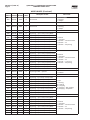
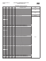
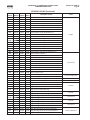
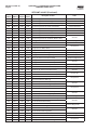
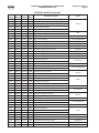
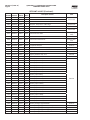
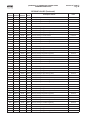
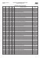
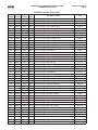
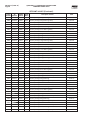
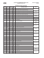
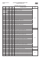
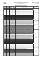
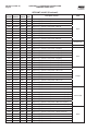
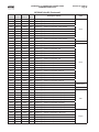
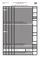
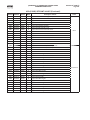
QUANTUM™ LX DATA TABLES..............................................................................................................................61
Digital Board Values..................................................................................................................................................62
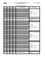
Analog Board Values.................................................................................................................................................64
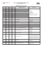
Calculated Values......................................................................................................................................................66
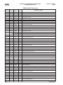
Mode Values..............................................................................................................................................................67
Timer Values.............................................................................................................................................................75
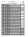
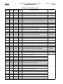
Setpoint Values.........................................................................................................................................................76
Commands................................................................................................................................................................97
DBS Setpoint Values..................................................................................................................................................98
General Setpoint Values............................................................................................................................................99
VSD (Vyper) Setpoint Values.......................................................................................................................................99
SECTION 7
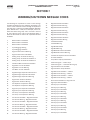
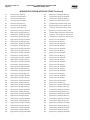
WARNING/SHUTDOWN MESSAGE CODES............................................................................................................103
SECTION 8
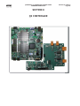
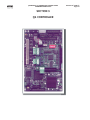
Q5 CONTROLLER.................................................................................................................................................110
Main Board History And Identification......................................................................................................................110
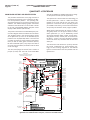
Communications Connector Locations.....................................................................................................................110
SERIAL COMMUNICATIONS HARDWARE..............................................................................................................111
General Description.................................................................................................................................................111
COM-1 and COM-2 Description................................................................................................................................111
COM-3 Description..................................................................................................................................................111
COM-4 Description..................................................................................................................................................111
SERIAL COMMUNICATIONS PORT WIRING...........................................................................................................112
General Note...........................................................................................................................................................112
RS-232 Wiring And Jumpers....................................................................................................................................112
RS-422/485 Wiring And Jumpers..............................................................................................................................112
RS-422 Signal Wiring........................................................................................................................................112
RS-485 Signal Wiring........................................................................................................................................112
SERIAL COMMUNICATIONS TROUBLESHOOTING.................................................................................................113
Troubleshooting RS-232..........................................................................................................................................113
Troubleshooting RS-422.........................................................................................................................................113
Troubleshooting RS-484.........................................................................................................................................113
COMMUNICATIONS DATA LOGGING SCREENS......................................................................................................115
090.020-CS (JUNE 11)
Page 4
QUANTUM™ LX COMPRESSOR CONTROL PANEL
COMMUNICATIONS SETUP
Communications Log...............................................................................................................................................115
Modbus TCP Log......................................................................................................................................................115
SECTION 9
QUANTUM 4 CONTROLLER..................................................................................................................................118
Main Board History And Identification......................................................................................................................118
QUANTUM 4 SERIAL COMMUNICATIONS HARDWARE.........................................................................................119
General Description.................................................................................................................................................119
COM-1 and COM-2 Description................................................................................................................................119
COM-3 Description..................................................................................................................................................119
SERIAL COMMUNICATIONS PORT WIRING...........................................................................................................120
RS-232 Wiring And Jumpers...................................................................................................................................120
RS-422/485 Wiring And Jumpers.............................................................................................................................21
RS-422 Signal Wiring........................................................................................................................................121
RS-485 Signal Wiring........................................................................................................................................122
SERIAL COMMUNICATIONS TROUBLESHOOTING.................................................................................................123
Troubleshooting RS-232..........................................................................................................................................123
Troubleshooting RS-422........................................................................................................................................123
Troubleshooting RS-484........................................................................................................................................124
COMMUNICATIONS DATA LOGGING SCREENS......................................................................................................125
Communications Log...............................................................................................................................................125
Modbus TCP Log.....................................................................................................................................................125
COMMUNICATIONS LOOPBACK TEST..................................................................................................................126
Description..............................................................................................................................................................126
Hardware Setup For Testing
RS-232.............................................................................................................................................................126
RS-422.............................................................................................................................................................126
RS-485.............................................................................................................................................................127
SOFTWARE SETUP FOR THE COMMUNICATIONS LOOPBACK TEST.....................................................................127
Performing The Communications Loopback Test....................................................................................................128
SECTION 10
APPENDIX A.......................................................................................................................................................130
Frick® Serial Communications Converter Module...................................................................................................130
Description......................................................................................................................................................130
Setting The Dipswitch......................................................................................................................................130
Mounting The Module.......................................................................................................................................130
Wiring The Module..........................................................................................................................................131
RS-232 Connections..................................................................................................................................131
RS-422 Connections..................................................................................................................................131
RS-485 Connections..................................................................................................................................131
APPENDIX B.......................................................................................................................................................132
Quantum™ LX Ethernet Communications Wiring....................................................................................................132
APPENDIX C.......................................................................................................................................................133
Quantum™ LX Local Ethernet Configurations..........................................................................................................133
APPENDIX D.......................................................................................................................................................134
Quantum™ LX Ethernet Network Configurations.....................................................................................................134
APPENDIX E.......................................................................................................................................................135
Quantum™ LX Serial Communications Wiring.........................................................................................................135
Serial Communications Wiring Diagrams.................................................................................................................138
To Customer Remote Computer/DCS...............................................................................................................138
RS-485 Communications...........................................................................................................................138
RS-422 Communications...........................................................................................................................138
The Quantum™ has the capability of being modified by the user/owner in order to obtain different performance characteristics. Any modification to the standard default settings may have a severe negative impact on the operation and performance of the equipment. Any modification to these control settings is the sole responsibility of the user/owner and Johnson
Controls disclaims any liability for the consequences of these modifications. It is possible that the modification of these
settings may cause improper operation and performance that result in property damage, personal injury or death. It is the
responsibility of the user/owner to evaluate and assess the consequences of their actions prior to modifying the controls
for this unit.
QUANTUM™ LX COMPRESSOR CONTROL PANEL
COMMUNICATIONS SETUP
090.020-CS (JUNE 11)
Page 5
SECTION 1
INTRODUCTION TO THE QUANTUM™ CONTROL SYSTEM
090.020-CS (JUNE 11)
Page 6
QUANTUM™ LX COMPRESSOR CONTROL PANEL
COMMUNICATIONS SETUP
INTRODUCTION TO THE QUANTUM™ LX
QUANTUM™ DESCRIPTION
The Quantum™ LX control panel currently utilizes two versions of microprocessor hardware, the
Quantum™ 4 and Q5 boards. The LX portion of
the Quantum™ name actually refers to the operating system (software), and the operator interface (physical display and keypad). When you
see the name Quantum™ 4 or Q5, the physical
hardware of the controller is being referred to
(microprocessor), whereas Quantum™ LX refers
to the software, and how the operator interacts
with the software (through the display/keypad).
As an example, the Quantum™ 4 and Q5 con-
trollers contain the physical Ethernet and Serial
connections that the user connects to, while the
Quantum™ LX software determines how those
connections are used. These connections are
known as PROTOCOLS.
The Quantum™ LX software is based on a Web
Browser format, and has the capability of communication through both Ethernet and Serial
Ethernet protocols.
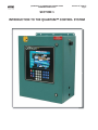
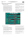
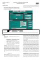
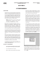
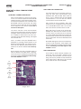
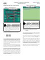
The following screen is representative of what
the operator will see after the unit has been
powered up. This is called the Home screen. Be
aware that the content of this screen may differ
from situation to situation, based upon the actual
configuration and installed options.
The Operating (or Home) screen
HOW TO USE THIS MANUAL
The purpose of this manual is provide the necessary information (protocols, data registers, wiring, etc.) to allow the end user to reliably communicate with the Quantum™ LX via various
communications methods (to be described later)
for the purpose of obtaining and sending data
and/or for compressor control.
The Quantum™ LX does NOT begin any communications conversations on its own, it only
responds to queries (requests) from external devices.
For Ethernet communications, refer to the sec-
tion entitled Ethernet and Networking. Ethernet
does not require any jumpers to be installed.
For serial communications connections, refer to
the section entitled Quantum™ Serial Communication for the correct wiring and jumper settings
of RS-232, RS-422, or RS-485. Also, refer to the
drawing of the Quantum™ 4 Main Board section
to identify wiring configurations for Com-2.
For information on software protocols, refer to
the section entitled Protocol Description.
To access specific data within the Quantum™ LX,
refer to the Data Tables.
QUANTUM™ LX COMPRESSOR CONTROL PANEL
COMMUNICATIONS SETUP
ETHERNET AND NETWORKING
DESCRIPTION
Frick® Controls uses Ethernet as the primary
method of connecting one or multiple Quantum™ LX panels to a common computer network. In the past, this interconnection would
have been done by serial protocol wiring, such
as RS-232/422/485. But with the capabilities of
today’s technology, Ethernet is the quickest and
most efficient way of providing this connectivity.
Whereas the old serial communications methods (RS232, etc.) were slow by today’s standards
(kilobits per second transmission speed), Ethernet is available in two speeds: 10 Mbps and 100
Mbps.
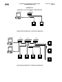
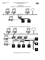
NOTE: For connection examples, refer to
the section of this manual entitled Quantum™ LX Local Ethernet Configurations and
Quantum™ LX Ethernet Network Configurations.
Ethernet is a data and information sharing system. It is a method of connecting one computer
to many others on a common network. This network can consist of both hardwired connections,
and wireless devices, hence the name ETHERNET.
Any Windows or Linux based computer is capable of accessing this network. All that is needed
is either a modem, USB port, or an Ethernet port.
These devices provide the necessary point of
connection for one end (branch) of the connection (a home computer for instance). The other
point that completes the connection is usually
provided by an Internet Service Provider (or ISP).
The Internet Service Provider usually has a very
large network router, or means of bring in many
individual connections. The router then assigns a
discrete and individual address to each connection (much like a street address). This address is
known as an Internet Protocol address (IP). The
IP address consists of a series of 4 to 12 digits,
and is normally transparent to the end user.
For individuals familiar with using the internet,
they are familiar that every time they activate
their web browser (the software that allows your
computer to connect), there is an address bar
that appears near the top of the screen. This address bar is where you would enter the IP address of the computer or network that you would
like to communicate with. To make this simpler,
these numeric IP addresses are also coded to
allow alpha-numeric names to be masked over
them, so that rather than having to enter an address of 216.27.61.137, you can simply enter in
www.jci.com, as an example. Although the actual process is more detailed and complicated than
this basic explanation, the end result is that most
of the work is being done invisibly.
090.020-CS (JUNE 11)
Page 7
The following write up describes how to set up
the Quantum™ LX to do this behind the scenes
work, so that it can communicate both at the
Internet level, and at a local Ethernet level.
CABLING
Each Quantum™ LX Ethernet connection must be
individually cabled (known as a homerun) direct
from a switch or computer. Unlike RS422/485
communications which allowed for cable daisychaining, Ethernet connections do not allow this.
This type of cabling is designed to handle the
100-Mbps speed needed by Ethernet. Both ends
of each cable must have an RJ-45 connector attached. The RJ-45 connector looks similar to the
RJ-11 connector on the end of a telephone cord
but is slightly larger (and not compatible). You
can buy Cat 5 cables in predetermined lengths
with the connectors already attached (for short
runs), or you can buy the cable in rolls, cut it to
length and install the RJ-45 connectors to the
ends (up to 100 meters per each cable run).
Although Frick® Controls recommends the use
of shielded, twisted pair Cat 5 cable, if the cable
is not properly constructed and tested, it can actually be more detrimental to the network than
unshielded cable. As long as all of the cables that
are used have been properly constructed AND
tested, either shielded or unshielded are acceptable. This is mostly due to the excellent (electrical) noise immunity that is inherent with Ethernet componentry.
NOTE: Follow standard networking procedures for the interconnections of all components. For individual cable runs in excess of
300 feet (~100 meters), a Switch/Hub must
be used for each additional run.
Cabling Do’s and Don’ts – Frick® Controls recommends the following guidelines when installing and using CAT 5 Ethernet cable:
Do:
•
•
•
•
•
•
•
Run all cables in a star (homerun)
configuration.
Keep all individual cable lengths
under 300 feet. If greater distances
are needed, use a switch/hub every
300 feet.
Ensure that the twists of the wire
pairs within the cable are maintained from end to end.
Make gradual bends in the cable.
Keep each bend radius over one
inch.
Keep all cables tie wrapped neatly.
Try to maintain parallel cable runs
where possible.
Keep the cable as far away as possible from EMI sources (motors,
090.020-CS (JUNE 11)
Page 8
•
•
•
•
QUANTUM™ LX COMPRESSOR CONTROL PANEL
COMMUNICATIONS SETUP
transformers, solenoids, lighting,
etc.)
Label the ends of each cable, to facility troubleshooting and identifying in the future.
Test each individual cable run with
an approved CAT5 E cable tester. A
TONING alone test is NOT acceptable.
Use rubber grommets anywhere
that the cable enters through a
hole in a metal panel.
ALWAYS obey local, national and
fire building codes.
Don’t:
•
•
•
•
•
•
•
•
Don’t install cable taut, cables
must always have some “play” or
slack in them.
Don’t over-tighten cable ties.
Don’t splice a cable. If a break
occurs, or the length is not long
enough (under 300 feet), replace
the entire run with an intact length.
Don’t tie cables to electrical conduits.
Don’t strip more than one inch
from the end of each cable when
installing end connectors.
Don’t sharply bend or kink the cable.
Don’t mix 568A and 568B wiring at
the same installation. 568B is the
most common wiring.
Don’t use excessive force when
pulling cable.
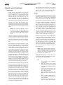
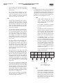
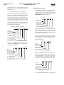
RJ-45 CONNECTORS
Ethernet network cables require the use of
industry standard RJ-45 plugs as shown below, for the termination of all cables:
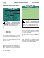
hubs, but a switch generally contains more
intelligence than a hub. Unlike hubs, network switches are capable of inspecting
the data packets as they are received, determining the source and destination device
of a packet, and forwarding that packet appropriately. By delivering messages only to
the connected device that it was intended
for, network switches conserve network
bandwidth and offer generally better performance than hubs.
The Switch takes the signal from each computer/Quantum™ LX and sends it to all of
the other computers/LX panels in your plant
or office. Switches come in several sizes,
noted by the number of ports available -- a
four-port Switch can connect four computers, an eight-port Switch can connect up to
eight computers and so on. So, if you start
with a four-port Switch but eventually add
more panels, you can buy another Switch
and connect it to the one you already have,
increasing the potential number of panels
on your network.
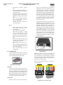
Typical Switch
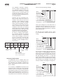
Note: If you want to connect one computer to
one Quantum™ LX, you can avoid the switch and
use a crossover Cat 5 cable. With a crossover
cable, you directly connect one Ethernet device
to the other without a Switch. To connect more
than two you need a Switch.
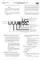
Refer to the following pictorial to construct a
crossover cable:
Typical RJ-45 Connector
THE HUB
A Hub is a common connection point for devices in a network. Hubs are commonly used
to connect segments of a LAN (Local Area
Network). They also contain multiple ports.
When a data packet arrives at one port, it
is copied to the other ports so that all segments of the LAN can see all packets.
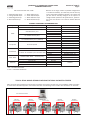
1 2 3 4 5 6 7 8
3 6 1 4 5 2 7 8
Left (Not
Crossed)
Right (Crossed)
THE SWITCH
Network Switches look nearly identical to
Both Ends of a crossover-cable
QUANTUM™ LX COMPRESSOR CONTROL PANEL
COMMUNICATIONS SETUP
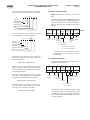
CAT-5 Ethernet cable color codes
1 – White w/orange stripe
2 – Orange w/white stripe
3 – White w/green stripe
4 – Blue w/white stripe
5 – White w/blue stripe
6 – Green w/white stripe
7 – White w/brown stripe
8 – Brown w/white stripe
090.020-CS (JUNE 11)
Page 9
Because of the large number of possible configurations
in an Ethernet network, you most likely will not have any
type of automated installation software. This means that
you will need to manually configure all the options. To
configure these options for the Quantum™ LX, please refer to the next section in this manual entitled Ethernet
Setup.
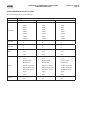
ETHERNET COMPONENT RECOMMENDATIONS
Component
Description
Shielded solid 4-pair* (1000 Ft)
Part Number
BOXCAT5E-DSSO
E-PLG-SOLID-SH
Shielded solid 4-pair*
CR45-100S
9504 CS
9504 F
Un-shielded solid 4-pair**
E-PLG-SOLID
345U5-1000BLK
Un-shielded solid 4-pair** (1000 Ft)
0-5EPCS-BK
HT-210C
P-15027
RJ-45 Crimp tool
S2307692
10-RJ1145
RJ-45 For Shielded 4-pair solid wire cable
P-15007
5-554169-3
RJ-45 For Un-shielded 4-pair solid wire cable 1-5E45-010
P-15029
TST-5150
Ethernet Cable Tester – Continuity only
TS075A-R2
Complete Cable I/O Qualification Tester
N/A
5 RJ-45 port
SFN-5TX
7 RJ-45 Port and 1 ST Fiber Optic Port
SFN-7TX/FX ST
8 RJ-45 port
SFN-8TX
Cable
Crimp Tool
Connectors
Cable Tester
Switches
Manufacturer
Cablesforless.com
VPI
Cables Direct
Alpha Wire Co.
VPI
Ram Electronics
Computercablestore.com
Cablesforless.com
Stonewall Cable, Inc.
Computers4sure.com
Computercablestore.com
Stonewall Cable, Inc.
Tyco Electronics
Computercablestore.com
Stonewall Cable, Inc.
Cablesforless.com
Black Box
Fluke
Phoenix
* STP = Shielded Twisted Pair
** UTP = Unshielded Twisted Pair
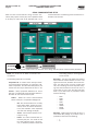
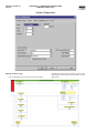
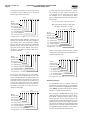
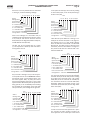
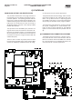
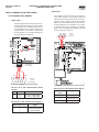
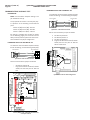
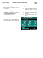
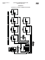
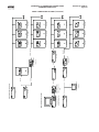
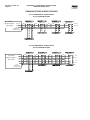
TYPICAL SERIAL WIRING SCENARIO INCLUDING OPTIONAL DBS MOTOR STARTER
After the serial communications wiring has been connected, and jumpers correctly set, the LX software needs to be setup
to match that of the device(s) that it is to communicate with. The following screen is where this information can be found:
External HMI communications
DBS Motor
Communications
1
DBS Motor
Communications
2
DBS Motor
Communications
3
DBS Motor
Communications
4
DBS Motor
Communications
5
090.020-CS (JUNE 11)
Page 10
QUANTUM™ LX COMPRESSOR CONTROL PANEL
COMMUNICATIONS SETUP
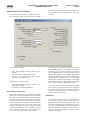
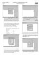
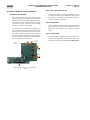
ETHERNET SETUP
The following section describes the suggested panel
setup for connecting the Quantum™ LX panel to an
existing Ethernet connection:
Once all of the cabling has been run and all connections have been made, it is now necessary to setup
the Quantum™ LX software to recognize and handle
the Ethernet connection.
ACCESSING:
Configuration
Ethernet
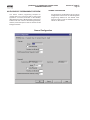
DESCRIPTION: This screen is used to allow the user to assign and setup Ethernet and Email communications parameters.
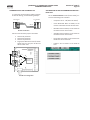
IP DATA
Address Type - The following drop-down menu is
provided:
•
•
Fixed (Static) – A fixed address is usually
assigned by the network (LAN) administrator, and is normally always the same.
DHCP (Dynamic) – Dynamic Host Configuration Protocol permits auto-assignment
of temporary IP addresses for new devices
connecting to the network.
IP Address – (Internet Protocol) Four setpoint boxes
are provided here. Every device on an Internet or
Ethernet network must be assigned a unique identifying number, called an IP Address (this is similar in
concept to the Quantum™ LX panel ID number). The
IP address is how the network identifies each device
that is attached. A typical IP address would look like
this:
•
216.27.61.137
Gateway Address – Four setpoint boxes are provided
here. This is the IP address for the computer or device
onto which your local network is connected to. This
gateway device is how all of the devices attached to
your local network are routed to other gateways and
networks. A router is a Gateway device that routes
packets between different physical networks. A gateway is a network point that acts as an entrance to
another network.
Subnet Mask - A TCP/IP number used to determine
to which TCP/IP subnet a device belongs. Devices in
the same subnet can be communicated with locally
without going through a router When a TCP/IP device
tries to communicate with another device the bits of
the TCP/IP destination address are "ANDed" with the
subnet mask to determine whether the address is
a local address (broadcastable) or must be reached
through a router. A subnet mask of 255.255.255.0 used
by a computer with a TCP/IP address of 10.10.10.1
would include the addresses 10.10.10.0 through
10.10.10.255 in the local network basically telling the
computer to try a router if it's transmitting to any
other IP address. This is all part of the TCP/IP protocol
Web Server Port – This is the port, or channel, that
a web server uses to communicate through. Just as
a computer sends data to a printer through a printer
port, a web server sends and receives data through
the Web Server Port. By default, the port number for
QUANTUM™ LX COMPRESSOR CONTROL PANEL
COMMUNICATIONS SETUP
a Web server is 80.
NAMING DATA
NOTE: The IP Address Type must be set to DHCP (Dynamic) for this section to work.
Host Name – Enter a distinct name that you wish to
be able to identify this particular compressor by (for
example; Unit1). The Host Name must be fifteen characters or less in length, use no spaces and use only
upper and lower case letters. It is similar in concept
to the function of the Panel ID, and basically allows
the network router to interpret the actual IP address
of a particular unit as this host name. When using a
web browser within the system network, this name
can be entered as the web location that you wish
to visit (instead of having to type in the IP address).
After modifying a Host Name, you will be required
to cycle power. The network router could take up to
fifteen minutes to recognize the change.
Work Group – All of the Quantum™ LX units within
a network may be grouped into different categories.
These categories could be unit locations, or perhaps categorized by unit function. For instance, if
you wanted to group the units by function, and had
10 units, and three of them were Evaporators (located on the roof), then Evap1 could be the name of
a work group. Another three units may be High Stage
compressors, this work group could be named HighStage1, and the remaining four units could be standard compressors, and they could be named Comp1.
So name each unit by these functional Work Group
names. The Work Group name must be fifteen characters or less in length, and can use numerals and
upper and lower case letters. When using the network neighborhood feature of Windows® Explorer,
by looking at your Network Neighborhood, you would
see the name of the Work Group, and within that
work group you would see the individual Host Names
of each unit within that work group. After modifying
a Work Group name, you will be required to cycle
power. The network router could take up to fifteen
minutes to recognize the change.
Server String – This is a comment area that can be
used in conjunction with the Host Name. For example, if the Host Name is Booster1, you could set the
Server String to print something like DockBooster, or
some other additional information about the unit. The
Server String has no control function; it is strictly an
informational area.
E-MAIL DATA
The purpose of the E-Mail data feature is to allow the
controller to send a Warning or Shutdown message
090.020-CS (JUNE 11)
Page 11
to defined listing of recipients.
Email Notification On Warning Or Shutdown – For the
E-mail notification feature to work, it must be enabled (it is disabled as a default). The following dropdown menu is provided:
•
•
Disabled
Enabled
Local Email Address - Use this setpoint box to enter
a valid E-mail address that has been assigned to the
internet account.
Alias Name For Local Email Address – Enter here a
custom name to identify more clearly the local Email
address. When a message is sent to all recipients,
this is the name that will appear in the Email FROM
column.
Subject - Enter a custom subject that you would like
to appear when a message failure is sent. When a
message is sent to all recipients, this is the wording
that will appear in the Email SUBJECT column.
SMTP Server Name OR IP Address - SMTP stands
for Simple Mail Transfer Protocol. SMTP servers
handle outgoing email, and accept email from other domains. When you set up an email client, you
must specify an outgoing server (sometimes called
an SMTP server). Often, this server is designated in
the form of smtp.domain.com. But this can vary, so
be sure to check with your email service provider or
LAN administrator to find out their outgoing server.
SMTP Server Port Number - This value is in almost
all cases going to be 25. This should be set by the
network or LAN administrator.
Comma-Delimited List Of Email Recipients - This is
simply the list of the Email addresses that you would
like to have any messages sent to. Separate each email address with a comma.
PROTOCOLS
The purpose of this section is to enable or disable the
Modbus TCP and Ethernet/IP parameters.
Modbus TCP:
•
•
Disabled
Enabled
Ethernet/IP:
•
•
Disabled
Enabled
090.020-CS (JUNE 11)
Page 12
QUANTUM™ LX COMPRESSOR CONTROL PANEL
COMMUNICATIONS SETUP
QUANTUM™ LX COMPRESSOR CONTROL PANEL
COMMUNICATIONS SETUP
090.020-CS (JUNE 11)
Page 13
SECTION 2
SERIAL COMMUNICATIONS
SERIAL COMMUNICATIONS DESCRIPTION
RS-232 DESCRIPTION
Almost all laptop and desktop computers have
at least one RS-232 serial communications
port available. It was initially developed for the
emerging computer industry in the 1960’s. Originally, it was a method of sending data from a
mini or main frame computer, to devices such as
printers, punch card readers, teletypes, magnetic
tape units and modems. In those early days, the
maximum speed at which RS-232 was capable
of transmitting (about 9600 bits per second),
was quite satisfactory, as most of the receiving
devices were mechanical in nature (except for
modems), and barely able to keep up with these
speeds.
RS-232 uses single ended TX (transmit data) and
RX (receive data). This means a common ground
wire is shared between TX and RX, so only 3
wires are needed for a data only serial channel:
TX, RX, and GND.
Disadvantages of single ended signaling is that
it is more susceptible to noise than differential
signaling (RS-422/485), effective cable distances
are shorter (typically about 50 Ft. total, due to
low noise immunity) and data rates are slower.
Additionally, there is the limitation that only two
devices can communicate together (master and
slave).
RS-422/RS-485 DESCRIPTION
When serial communications started moving
into the industrial environment, it was quickly
noted that because of the high electrical noise
potential from electric motors, valves, solenoids,
fluorescent lighting, etc., that the noise immunity
characteristics of RS-232 protocol was grossly
lacking. Additionally, the distances between the
communicating equipment on the factory floor
was much greater than that within the typical office environment. For these reasons, RS-422 and
RS-485 was developed.
•
RS-422 is a full duplex communications
hardware protocol. This means that it data
can be sent and received simultaneously.
Frick® Controls uses a 4-wire system for
RS-422 (two transmit wires and two receive
wires). Advantages of RS-422 over RS-232
is that up to 30 Quantum™ controllers may
be simultaneously connected using a daisychain wiring scheme (to be explained later),
and that the distances involved can be much
greater (typically up to 2000 ft. for the total cable run), much greater noise immunity
than RS-232.
•
RS-485 is a half duplex bus. This means that
it can only send data, or receive data at any
given time. It cannot do both at the same
time. Frick® Controls uses a 2-wire system
for RS-485 one positive transmit/receive
wire and one negative transmit/receive
wire). Up to 30 Quantum™ controllers may
be simultaneously connected up to a total
distance of 2000 ft. using a daisy-chain wiring scheme (to be explained later). One advantage to using RS-485 as opposed to RS422 is that only a single twisted pair cable
need to be run to all devices (while RS-422
requires a double twisted pair cable), much
greater noise immunity than RS-232.
090.020-CS (JUNE 11)
Page 14
QUANTUM™ LX COMPRESSOR CONTROL PANEL
COMMUNICATIONS SETUP
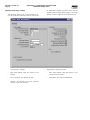
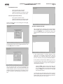
SERIAL COMMUNICATIONS SETUP
After the serial communications wiring has been connected, and jumpers correctly set, the LX software needs
to be setup to match that of the device(s) that it is to
ACCESSING:
Configuration…
communicate with. The following screen is where this information can be found:
Communication
DESCRIPTION: The purpose of this screen is to allow the user to assign and setup serial communications parameters.
NOTE: This screen has no affect on Ethernet communications.
The following setpoints are provided:
Compressor ID - A number that is used by an external communications application, to converse to individual compressors. On interconnected systems, this
number must be unique. Valid values are from 1 – 99.
Comm1 - (Setup parameter definitions for Com-1
and Com-2 are identical) Communications related information for the communications ports:
Status - Shows the current communications
status of the port. The possible messages are:
•
Off - No communications are currently
taking place. NOTE: A delay of 15 seconds or more of inactive communications (time between valid responses)
will cause this message to display.
•
Active - Valid communications are actively occurring.
•
Failed - An invalid command was received by the port. This could be due
to a bad checksum value, a wiring issue, or hardware problem at either the
transmitting (host) or receiving (Quantum™ LX) end.
Baud Rate - The baud rate defines the speed at
which external communications can occur. The
higher the baud rate, the faster the communications. It is best to start out using a lower baud
rate, and increasing the value only after verifying that communications errors do not occur. If
errors start to occur, drop the baud rate back
down. A pull down menu is provided to select
from the following:
•
•
•
•
•
•
•
•
1200
2400
4800
9600
19200
38400
57600
115200
Data Bits - Determines the number of bits in a
transmitted data package. A pull down menu is
provided to select from the following:
•
•
7
8
QUANTUM™ LX COMPRESSOR CONTROL PANEL
COMMUNICATIONS SETUP
Stop Bits - A bit(s) which signals the end of a
unit of transmission on a serial line. A pull down
menu is provided to select from the following:
•
•
1
2
Parity - In communications, parity checking refers to the use of parity bits to check that data
has been transmitted accurately. The parity bit is
added to every data unit (typically seven or eight
data bits) that are transmitted. The parity bit for
each unit is set so that all bytes have either an
odd number or an even number of set bits. Parity checking is the most basic form of error detection in communications. A pull down menu is
provided to select from the following:
•
•
•
None
Even
Odd
Protocol - A protocol is the special set of rules
that each end of a communications connection
use when they communicate. A pull down menu
is provided to select from the following Frick
recognized protocols:
•
•
•
•
•
•
•
•
None
Frick
ModBus ASCII
ModBus RTU
AB DF1 Full Duplex
AB DF1 Half Duplex
DBS Motor Starter
Vyper
Map File - Because the addressing scheme between
the Quantum™ version 5.0x and earlier software and
the Quantum™ LX version 6.0x and later software is
not the same, this file was created. The map file is a
conversion utility that can be used to allow a communications application that was previously written
by the user under the Quantum™ version 5.0x and
earlier to function properly with the Quantum™ LX by
redirecting the old addresses to the new addresses
(see the section entitled Using the MAP file for additional information). A pull down menu is provided
to select from the following:
•
No - Do not use map file. The user is either
not going to be using external communications, or they will be writing the communication application based upon Quantum™
LX addresses.
•
Yes - The user has an application that was
previously written for the Quantum™ version 5.0x or earlier, and they want to utilize
the same code for the Quantum™ LX.
I/O Comms - A status indicator is provided to show
the current state of the internal communications of
the I/O boards. The possible displayed states are:
•
Off - Loss of or intermittent communica-
090.020-CS (JUNE 11)
Page 15
tions failures to the internal Quantum™ LX
I/O boards.
•
Active - Indicates that normal I/O communications are occurring.
•
Failed - Loss of communications, a shutdown message will be generated.
Redetect IO Comms - Select this key to detect all
connected Analog and Digital boards. If a board has
been removed, a communication error shutdown will
be issued until this key is selected. Reference the
About screen to view what has been detected.
Two keys are located at the bottom right hand side of the
screen. The following describes there function:
Download MapFile.txt from Quantum™ LX – With
a USB memory stick installed on the LX, pressing this
key will cause the MapFile.txt file to be downloaded
from the Quantum™ LX into the USB memory.
Upload MapFile.txt to Quantum™ LX – After the
user has modified the MapFile.txt file to suit their
needs, pressing this key will cause the file to be uploaded from the USB memory back into the Quantum™ LX.
USING THE MAP FILE
The MAP file is simply a text file (map.txt), which can
be downloaded from the Quantum™ panel. The file
can be used in its original format, which contains a
limited number of addresses, or may be modified by
the user, to incorporate additional addresses.
Downloading The Map File From The Quantum™
LX Through a Web Browser:
To download the map file from the Quantum™
LX controller, click the Download button. A new
box will appear with a link labeled MapFile.txt.
Right click on the link, and select Save Link Target As… from the menu. The web browser will
then present a dialog box allowing the user select a location on their computer for the map file
to be stored. (NOTE: This operation is not intended to be performed from the Operator Interface Panel. Instead, a desktop computer should
be used to access the Evaporator controller via
a web browser).
Downloading the MAP File From the Panel Using a
USB Memory Stick:
Two keys are located at the bottom right side of
the screen. The following describes there function:
Download MapFile.txt from Quantum™
LX – With a USB memory stick installed
on the LX, pressing this key will cause the
MapFile.txt file to be downloaded from the
090.020-CS (JUNE 11)
Page 16
QUANTUM™ LX COMPRESSOR CONTROL PANEL
COMMUNICATIONS SETUP
Quantum™ LX into the USB memory.
memory back into the Quantum™ LX.
Upload MapFile.txt to Quantum™ LX –
After the user has modified the MapFile.txt
file to suit their needs, pressing this key will
cause the file to be uploaded from the USB
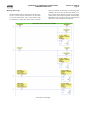
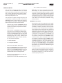
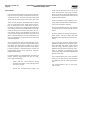
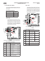
A sample of the original file appears in the following example:
;Quantum to Quantum LX MAP Addresses
;Q,
LX ,
LX Description
0,
1026
;Compressor Motor Start Signal
1,
1027
;Compressor Motor Starter-Feedback/Compressor Interlock
2,
1028
;Oil Pump Start Signal
3,
1029
;Oil Pump Feedback
4,
1003
;Capacity Increase
5,
1002
;Capacity Decrease
6,
1005
;Volume Increase
7,
1004
;Volume Decrease
Quantum™ Version 5.0
and earlier addresses
Quantum™ LX
addresses
Quantum™ LX
Address Description
MapFile.txt Example
USB Memory Stick location
Quantum™ 4
Q5
QUANTUM™ LX COMPRESSOR CONTROL PANEL
COMMUNICATIONS SETUP
090.020-CS (JUNE 11)
Page 17
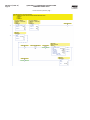
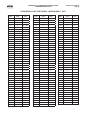
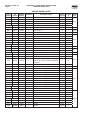
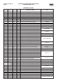
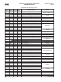
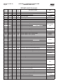
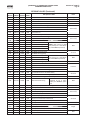
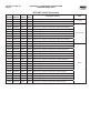
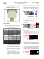
SERIAL COMMUNICATION SETUP TABLE
Use the following form to record all settings:
Compressor ID
_______ (0 - 255)
Com 1
Baud Rate
Data Bits
Stop Bits
Parity
Protocol
Map File
Com 2
Com 3
1200
1200
1200
2400
2400
2400
4800
4800
4800
9600
9600
9600
19200
19200
19200
38400
38400
38400
57600
57600
57600
115200
115200
115200
7
7
7
8
8
8
1
1
1
2
2
2
None
None
None
Even
Even
Even
Odd
Odd
Odd
None
None
None
Frick
Frick
Frick
Modbus ASCII
Modbus ASCII
Modbus ASCII
Modbus RTU
Modbus RTU
Modbus RTU
AB DF1 Full Duplex
AB DF1 Full Duplex
AB DF1 Full Duplex
AB DF1 Half Duplex
AB DF1 Half Duplex
AB DF1 Half Duplex
DBS Motor Starter
DBS Motor Starter
DBS Motor Starter
Vyper
Vyper
Vyper
None
None
None
No
No
No
Yes
Yes
Yes
090.020-CS (JUNE 11)
Page 18
QUANTUM™ LX COMPRESSOR CONTROL PANEL
COMMUNICATIONS SETUP
SERIAL PROTOCOL
5.
DESCRIPTION
The use of serial communication protocols permits data transmission between devices. Protocol determines how contact is established and
how the query (question) and response (answer)
takes place. The information in a message command requires:
•
•
•
•
6.
•
The identity of the intended receiver (ID
#)
What the receiver is to do (read or
write to a setpoint, etc.)
Data needed to perform an action (the
value of a setpoint to be changed)
A means of checking for errors (checksum).
When using any of the communications ports,
check what communication protocol has been
selected from the Communications screen. The
baud rate, data bits, stop bits, parity and connection type of all comm. ports, as well as the
panel ID number are also changed from this
screen, and should coincide with the setup of
the other device.
Note: The data communication protocols are continuously being expanded and
improved. Therefore, you should consult
Frick® Controls for the exact details on your
particular unit(s) before developing system
software to interface with the panel.
munication port.
Enter the Quantum™ LX ID. This will be
used to identify commands that are sent to
it.
Wire to the first panel via RS-232 (Quantum™ 4), RS-422, or RS-485 to the Quantum™ LX Comm Port.
•
•
7.
8.
9.
Send a single command to read data from
this Quantum™ LX using its ID.
Check if you received a data response at
your device.
Troubleshooting when you don’t receive a
data response:
•
QUANTUM™ LX COMMUNICATIONS PROTOCOL LIST
•
The Quantum™ LX controller has the capability
of communicating to the outside world through
the following software protocols:
•
•
•
•
•
•
•
•
Frick®
Allen-Bradley DF-1 Full Duplex
Allen-Bradley DF-1 Half Duplex
Modbus ASCII
Modbus RTU
Modbus TCP
Ethernet/IP
CHECKLIST FOR SETTING UP COMMUNICATION
1.
2.
3.
4.
Decide which Quantum™ protocol you can
communicate with and want to use.
Setup your device’s communication port
with the proper parameters and select a
baud rate.
Next, setup the Quantum™ LX for the desired communication protocol. Select the
protocol from the Communications screen.
Set the baud rate of the Comm Port to coincide with the setup of your device’s com-
If you are communicating to more
than one panel, then you will not
be able to use RS-232. You can
however, convert RS-232 to either
RS-422 or RS-485 with an adapter
card. Reference the Converting
an RS-232 Serial Port to RS-422
or RS-485 section for information
about an adapter card.
Refer to the drawing of the Quantum™ LX Main Board in this manual to identify wiring and jumper
locations for the Comm Ports.
Refer to the Main Board Communications section in this manual for
the correct jumpering of RS-232
(Quantum™ 4), RS-422, or RS-485.
•
•
•
•
Check to see if the status of the
Comm Port on the Communications screen is showing ACTIVE or
OFF.
ACTIVE is shown only when the
Quantum™ LX understands it is
receiving a properly composed
message.
Check that the RX I/O communication activity lamp on the Quantum™ LX Main Processor Board is
blinking as it receives the instruction from your device.
A steady lit RX LED or one that
isn’t lighting, are signs of improper
wiring.
If the RX LED is properly blinking,
then check if the TX LED is blinking
in response.
If the TX is not blinking then check
the communication protocol setup
at the panel, the panel’s ID and the
Comm Port baud rate setting.
If the TX is blinking, then check
that the Comm Port communication jumpers are correct.
Note: A useful tool for troubleshooting is Windows HyperTerminal. Refer to the HyperTerminal
Setup section in this manual for more information.
QUANTUM™ LX COMPRESSOR CONTROL PANEL
COMMUNICATIONS SETUP
If you properly receive data and need to communicate to more than one panel, then setup
and wire to another panel. Reference the wiring diagram drawings in the back of this manual.
Send a single command to read data from this
Quantum™ LX using its ID and troubleshoot as
above, if necessary. To prevent noise feedback
which is possible when communicating over a
long distance, only the last panel should have the
termination jumpers installed.
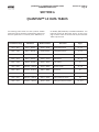
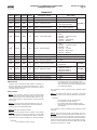
FRICK® PROTOCOL
The following is a complete list of available Frick® Protocol # commands:
COMMAND CODE and DESCRIPTION
I
= Returns compressor status (I)nformation
R
= Compressor sta(R)t control
S
= Compressor (S)top control
A
= Return full load (A)mps information
V
= Slide (V)alve/Slide stop control
MC
= Change (M)ode of (C)ompressor
MV = Change (M)ode of Slide (V)alve
DESCRIPTION
All commands for Frick® protocols must
be in ASCII to be recognized (see the Conversion Chart For Decimal / Hexadecimal
/ ASCII, located later in this manual). The
commands can be in upper or lower case
letters. A compressor with an ID code of
[00] is considered disabled. ID codes from
[01] through [99] are valid and recognized
by the Quantum™.
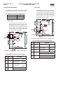
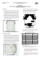
FRICK® # PROTOCOL SPECIFICATIONS
Frick # protocol consists of commands that
are available for most other existing models of Frick compressor control panels. The
Frick # protocol does not utilize a checksum.
It is better to use Frick Quantum™ ($) protocol when only communicating to Quantum™ 4A or Quantum™ LX panels.
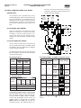
When there is more than one panel, a Quantum™ LX can be wired from its communications ports to another panels’ ports, or can
be wired to Port 1 of a RWB, RDB, RXB or
RXF Micro Plus panel.
Frick® RWB, RDB, RXB, or RXF Panel Frick® #
Communications Port #1 RS-422 Pinout
9
8
5
4
090.020-CS (JUNE 11)
Page 19
- TX (Transmit)
+ TX (Transmit)
- RX (Receive)
+ RX (Receive)
P
= Return (P)ressures information
T
= Return (T)emperatures information
Q
= (Q)uery setpoints data
C
= Enter (C)hange setpoints mode
F
= Return (F)ailures
KF
= (K)Clear (F)ailures
KR
= (K)Clear remaining (R)ecycle delay time
All data is returned as integer values. If decimal positions
are assumed, then divide the data by the proper multiple
of 10 to get the actual value.
Temperature data, except for Suction Temperature, is
returned in the current temperature units as 3 characters with no decimal position (i.e. 032 would represent
32 degrees Fahrenheit if the panel temperature units are
in Fahrenheit, or it would represent 32 degrees Celsius, if
the panel temperature units are in Celsius). Suction Temperature is returned as 4 characters with a + or – as the
leading character (i.e. –010 would represent –10 degree).
Pressure data is usually returned in the current pressure
units. However, the Filter differential reading is always returned in PSIA. When in PSIG or in PSIA, the pressure
data is returned as 3 characters with no decimal position.
However; in order to show the full transducer range, the
#IDPS command returns 4 characters with one decimal
position assumed. The #IDI, and #IDPA commands return
3 characters that assume one decimal position; therefore,
99.9 is the highest value that can be returned. When in
PSIG, suction pressure is returned in PSIA. When in Bar
and BarA, the pressure data is returned as 4 characters
with two decimal positions assumed. When in KpaA, the
pressure data is returned as 4 characters with no decimal
position.
090.020-CS (JUNE 11)
Page 20
QUANTUM™ LX COMPRESSOR CONTROL PANEL
COMMUNICATIONS SETUP
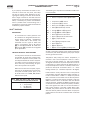
The following is a detailed description of each command:
RETURN COMPRESSOR STATUS INFO:
#IDI
Command structure:
Command
COMPRESSOR START CONTROL:
Description
#
Start of command sequence
ID
Compressor (ID) code (01, 14, etc.)
I
1, 2, 3
Return Status (I)nformation command
4
5
6
7
8, 9, 10
Description of returned data
=
(R)emote
A
=
(A)uto
M =
(M)anual
R
=
(R)unning
O
=
(O)ff
(Slide Valve)
(S)lide Valve too high
P
=
(P)ermissive Start not energized
I
=
d(I)fferential Pressure too high
T
=
s(T)opping
Au(X) not energized
U
=
(U)nable to start
R
=
(R)emote
M =
(M)anual
A
=
(A)uto
C
=
(C)utout (Shutdown)
A
=
(A)larm
N
=
(N)ormal
Start command sequence
ID
Compressor (ID) code (01, 14, etc.)
R
Sta(R)t compressor command.
ID
(ID) code repeated for verification
Returned answer:
1
=
=
Description
#
Character
Position
S
X
Command
NOTE: The compressor must be in the remote Start
Mode for this command to be executed.
Slide Valve position.
R
#IDRID
Command structure:
Returned Answer, ie: 090RRRN340
Character
Position
Note: The following control commands are for remote
control of a compressor. A compressor should be in both
remote compressor mode and remote Slide Valve or capacity mode for remote control.
Description of returned data
(A)cknowledge
2, 3
(ID) code verified
CR, LF (Carriage return, line feed)
COMPRESSOR STOP CONTROL:
#IDSID
Command structure:
Command
(Compressor
mode)
#
Start command sequence
ID
Compressor (ID) code (01, 14, etc.)
S
(S)top compressor command.
ID
(ID) code repeated for verification
NOTE: The compressor must be in the remote
Start mode for this command to be executed.
Suction value in PSIA.
CR, LF (Carriage Return, Line Feed)
Description
Returned answer:
Character
Position
1
2, 3
Description of returned data
(A)cknowledge
(ID) code verified
CR, LF (Carriage return, line feed)
QUANTUM™ LX COMPRESSOR CONTROL PANEL
COMMUNICATIONS SETUP
RETURN FULL LOAD AMPS COMMAND:
#IDA
RETURN SLIDE STOP POSITION COMMAND:
#IDVP
Command structure:
Command structure:
Command
090.020-CS (JUNE 11)
Page 21
Command
Description
Description
#
Start command sequence
#
Start command sequence
ID
Compressor (ID) code (01, 14, etc.)
ID
Compressor (ID) code (01, 14, etc.)
A
Return Full Load (A)mps command
V
Slide (V)alve / Slide Stop command
P
Return Slide Stop (P)osition value
Returned Answer:
When using the A command, the returned Full Load
Amps will be:
XXX = 3 characters followed by a CR, LF.
Returned Answer:
Character
Position
Description of returned data
1, 2
SLIDE VALVE CONTROL COMMANDS:
CR, LF (Carriage return, line feed)
#IDVS
#IDVUXX
Command structure:
Command
Slide Stop position, i.e. 25 = 2.5
#IDVLXX
Description
CHANGE COMPRESSOR MODE
COMMAND:
#IDMCmID
Command structure:
#
Start command sequence
ID
Compressor (ID) code (01, 14, etc.)
V
Slide (V)alve / Slide Stop command
#
Start command sequence
L
(L)oad Slide Valve command
ID
Compressor (ID) code (01, 14, etc.)
U
(U)nload Slide Valve command
MC
Change (M)ode of (C)ompressor
XX = 00
XX = 01 to
15
S
Turns selected output off
Turns selected output on for XX seconds
Return (S)lide Valve position value
If the command was #01VL00, then the load Slide Valve
output on compressor #1 would be turned off. If the
command was #01VL05, then the load Slide Valve output on compressor #1 would be turned on for 5 seconds,
and would then automatically turn off. NOTE: the Slide
Valve must be in the remote mode for this command
to be executed. Time is not accrued, each command
restarts timer.
Returned Answer (for L or U commands):
Character
Position
1
2, 3
Description of returned data
(A)cknowledge
(ID) code verified
(Carriage return, line feed.)
Returned Answer (for S command):
Character
Position
1, 2, 3
Command
Description of returned data
Slide Valve position.
CR, LF (Carriage return, line feed)
m
Description
=
O
(O)ff
=
A
(A)uto
=
R
(R)emote
ID
(ID) code repeated for verification
Returned Answer:
Character
Position
1
2, 3
Description
(A)cknowledge
(ID) code verified
(Carriage return, line feed)
090.020-CS (JUNE 11)
Page 22
QUANTUM™ LX COMPRESSOR CONTROL PANEL
COMMUNICATIONS SETUP
CHANGE SLIDE VALVE MODE
COMMAND:
#IDMVmID
Command
Description
#
Start command sequence
ID
Compressor (ID) code (01, 14, etc.)
MV
(M)ode of Compressor Slide (V)alve
m
=
O
(O)ff
=
A
(A)uto
=
R
(R)emote
ID
X
(ID) code repeated for verification
Returned Answer:
Description
2, 3
X
Start command sequence
Compressor (ID) code (01, 14, etc.)
T
Return (T)emperature command
=
S
Return (S)uction Temperature
=
D
Return (D)ischarge Temperature
=
O
Return (O)il Temperature
=
P
Return Se(P)arator Temperature
=
A
Return (A)ll temps as a string of data
Returns the Suction Temperature
(A)cknowledge
#01TD
Returns the Discharge Temperature
(ID) code verified
#01TO
Returns the Oil Temperature
(Carriage return, line feed)
#01TP
Returns the Separator Temperature
#01TA
Returns All Temperatures
#IDPX
Command structure:
Description
#
Start command sequence
ID
Compressor (ID) code (01, 14, etc.)
P
Return (P)ressures command
=
#
ID
#01TS
RETURN PRESSURES COMMAND:
Command
Description
Command Examples: (Compressor #01 is used here)
Character
Position
1
#IDTX
Command structure:
Command structure:
Command
RETURN TEMPERATURES COMMAND:
S
Return (S)uction Pressure (PSIA)
=
D
Return (D)ischarge Pressure (g/hg)
=
O
Return (O)il Pressure (g)
=
F
Return (F)ilter differential Pressure
=
A
Return (A)ll pressures as a string of
data
Command Examples: (Compressor #01 is used here)
#01PS
Returns the Suction Pressure
#01PD
Returns the Discharge Pressure
#01PO
Returns the Oil Pressure
#01PF
Returns the Filter Differential Pressure
#01PA
Returns All pressures
Note: Don’t send CR or LF
Returned Answer:
If using the S command the returned pressure will be:
XXXX = 4 characters followed by a CR, LF.
If using the D, O or F commands, the returned pressure
will be: XXX = 3 characters followed by a CR, LF.
If using the A command, the returned data would be:
XXXXXXXXXXXX = 12 characters followed by a CR, LF.
Note: Don’t send CR or LF
Returned Answer:
If using the S command the returned temp. will be:
+/-XXX = The first character will be a + or -, followed
by 3 characters and ending with a CR, LF.
If using the D, O or P commands, the returned temp.
will be:
XXX = 3 characters followed by a CR, LF.
If using the A command, the returned data would be:
XXXXXXXXXXXX = 12 characters followed by a CR, LF.
QUANTUM™ LX COMPRESSOR CONTROL PANEL
COMMUNICATIONS SETUP
QUERY SETPOINTS DATA:
#IDQ1
Command structure:
Command
Description
#
Start command sequence
ID
Compressor (ID) code (01, 14, etc.)
Q1
(Q)uery Setpoints command
Returned Answer:
QUERY SETPOINTS DATA:
#IDQ2
Command structure:
Command
Description
#
Start command sequence
ID
Compressor (ID) code (01, 14, etc.)
Q2
(Q)uery Setpoints command
Returned Answer:
Character
Position
#
Byte(s)
1
1
Always 0
2, 3, 4, 5
4
Capacity Control Setpoint, 3
chars followed by g or h
14, 15
2
Prop band
16, 17
2
Dead band
18, 19
2
Cycle time
20, 21, 22, 23
4
Future
24, 25, 26, 27
4
Future
28, 29, 30, 31
4
Future
32, 33
2
Future
34, 35
2
Future
36, 37
2
Future
4
High Discharge Pressure
Shutdown
42, 43, 44, 45
4
High Discharge Pressure
Warning
46
1
ID (tenths position byte)
47
1
ID (ones position byte)
48
1
ID Checksum of all data (pos.
1 to 47)
49
1
CR code 13
50
1
LF code 10
51
1
0 null terminator char.
38, 39, 40, 41
090.020-CS (JUNE 11)
Page 23
Setpoint (Name/Comment)
Character
Position
# Byte(s)
Setpoint (Name/Comment)
1, 2, 3
3
Future
4, 5, 6
3
Future
7, 8, 9
3
MLC amps stop load
10, 11, 12
3
MLC amps force unload
13, 14, 15
3
CT factor
16, 17
2
Recycle delay (setpoint,
not time left)
18
1
Aux 1
0=
Warning
1=
Shutdown
19
1
Aux 1
0 = NO
1 = NC
20
1
Aux 2
0=
Warning
1=
Shutdown
21
1
Aux 2
0 = NO
1 = NC
22
1
Future
23, 24
2
Future
25
1
Future
26
1
Future
27, 28
2
Future
29
1
Future
30
1
ID (tenths position byte)
31
1
ID (ones position byte)
32
1
ID Checksum of all data
(pos. 1 to 47)
33
1
CR code 13
34
1
LF code 10
35
1
0 null terminator char.
090.020-CS (JUNE 11)
Page 24
QUANTUM™ LX COMPRESSOR CONTROL PANEL
COMMUNICATIONS SETUP
QUERY SETPOINTS DATA:
#IDQ3
#IDC
Command structure:
Command structure:
Command
CHANGE SETPOINTS COMMAND:
Command
Description
Description
#
Start command sequence
#
ID
Compressor (ID) code (01, 14, etc.)
ID
Compressor (ID) code (01, 14, etc.)
Q3
(Q)uery Setpoints command
Returned Answer:
Character
Position
#
Byte(s)
Setpoint (Name/Comment)
1, 2, 3, 4
4
Spaces
5, 6, 7, 8
4
Future
9
1
Setback
active
10, 11, 12, 13
4
Auto. Cycling compressor Start
14, 15, 16, 17
4
Auto. Cycling compressor Stop
1 = Yes
0 = No
Start command sequence
C
(C)hange setpoint command
xx
Which setpoint
xxx
New value
y
g or h for gauge or inches
The following is the complete list of setpoints that may
be changed while in the change setpoints command:
01xxxy
Capacity Control Setpoint
(y deleted for KpaA & BarA ver.)
02xxxy
Change Low Suction Shutdown Setpoint
(y deleted for KpaA & BarA ver.)
03xxxy
Capacity Low Suction Alarm Setpoint
(y deleted for KpaA & BarA ver.)
04xxx
Change High Press. Shutdown Setpoint
(xxxx is used for KpaA & BarA ver.)
05xxx
Change High Press. Alarm Setpoint
(xxxx is used for KpaA & BarA ver.)
18, 19
2
Future
20, 21
2
Future
22, 23
2
Autocycle minimum Slide Valve
24
1
Autocycle
active
25, 26, 27, 28
4
Future
29, 30, 31, 32
4
Future
06xxx
Change MLC Stop Load Setpoint
33, 34
2
Future
07xxx
Change MLC Force Unload Setpoint
35, 36
2
Future
08xx
Change Recycle Delay Setpoint
37, 38
2
Future
09xxx
Change CTF Setpoint
Proportional Band
1 = Yes
0 = No
39
1
Future
10xx
40
1
ID (tenths position byte)
11xx
Dead Band
41
1
ID (ones position byte)
12xx
Cycle Time
42
1
ID Checksum of data (positons
1-47)
43
1
CR code 13
44
1
LF code 10
45
1
0 null terminator char.
01
Compressor ID code
Returned Answer:
Axxxx
The new setpoint which was sent
followed by a carriage return, line
feed. BAD followed by the ID, CR, LF if
unsuccessful.
Returned Example 1: If #01C01300g01 is sent:
The capacity control setpoint would be changed to
30.0g and the returned answer is A300g followed by a
CR, LF.
Returned Example 2: If #01C0711001 is sent:
The MLC force unload setpoint would be changed to
110% and the returned answer is A110 followed by a
CR, LF.
Returned Example 3: If #01C0520002 is sent:
The returned answer is BAD followed by the ID number and a CR, LF.
QUANTUM™ LX COMPRESSOR CONTROL PANEL
COMMUNICATIONS SETUP
RETURN FAILURE COMMAND:
#IDF
CLEAR FAILURE COMMAND:
#IDKFID
Command structure:
Command structure:
Command
090.020-CS (JUNE 11)
Page 25
Command
Description
Description
#
Start command sequence
#
Start command sequence
ID
Compressor (ID) code (01, 14, etc.)
ID
Compressor (ID) code (01, 14, etc.)
F
Return Discrete (F)ailures List
KF
(K)Clear (F)ailures
ID
(ID) code repeated for verification
Returned Answer:
Character
Alarm
Position
Description
1
2
3
4
5
High Discharge Pressure
Shutdown
High Discharge Pressure
Warning
Low Suction Pressure
Shutdown
Low Suction Pressure
Warning
Low Oil Pressure Shutdown and/or Differential
Oil Pressure Shutdown
6
Low Oil Pressure Warning
7
High Oil Temp. Shutdown
8
High Oil Temp. Warning
9
Low Oil Temp. Shutdown
10
Low Oil Temp. Warning
11
12
13
14
High Discharge Temp.
Shutdown
High Discharge Temp.
Warning
Compressor Aux. FailShutdown
Pump Aux. Fail- Shutdown
15
Oil Level Shutdown
16
Unused - 0
17
High Oil Filter Pressure
Warning
18
Unused - 0
19
Aux. 1 Alarm/Shutdown
20
Aux. 2 Alarm/Shutdown
21
Low Motor Current Shutdown
22
Sensor Fault
23
Unused - 0
24
Unused - 0
Returned Answer:
0 = Safe
1 = Shutdown
0 = Safe
1 = Warning
0 = Safe
1 = Shutdown
0 = Safe
1 = Warning
Character
Position
1
2, 3
Description
(A)cknowledge
(ID) code verified
(Carriage return, line feed)
0 = Safe
1 = Shutdown
CLEAR ANTIRECYCLE COMMAND:
0 = Safe
1 = Warning
0 = Safe
1 = Shutdown
0 = Safe
1 = Warning
0 = Safe
1 = Shutdown
0 = Safe
1 = Warning
0 = Safe
1 = Shutdown
0 = Safe
1 = Warning
0 = Safe
1 = Shutdown
0 = Safe
1 = Shutdown
0 = Safe
1 = Shutdown
Command structure:
0 = Safe
1 = Warning
0 = Safe
1 = Shutdown
0 = Safe
1 = Shutdown
0 = Safe
1 = Shutdown
0 = Safe
1 = Warning
NOTE: Returns a 24 char data string followed by ID, CR, LF.
Command
#IDKRID
Description
#
Start command sequence
ID
Compressor (ID) code (01, 14, etc.)
KR
(K)Clear (R)ecycle Delay
ID
(ID) code repeated for verification
Returned Answer:
Character
Position
1
2, 3
Description
(A)cknowledge
(ID) code verified
(Carriage return, line feed)
090.020-CS (JUNE 11)
Page 26
QUANTUM™ LX COMPRESSOR CONTROL PANEL
COMMUNICATIONS SETUP
QUANTUM™ $ PROTOCOL SPECIFICATIONS
Quantum™ ($) protocol commands are used by both
the Quantum™ and the Quantum™ LX. This protocol has been modified slightly for the LX, in that the
D command has been eliminated, and the addressing structure has changed. Any previously configured
Quantum™ LX protocol applications that had been
written for Quantum™ panels, will still work for the
LX, by using the Map File on the Communications
Screen.
Unless otherwise shown, 9 characters are returned
from the Quantum™ for a data value. The data value
includes two decimal fields and the first character
position is either; - if the value is negative, or it is
+ if the value is positive. For example, if the data’s
value is 25.5; then the value +00002550 is sent. All
temperatures are in degree C and all pressures are
in PSIA. A mode such as Slide Valve mode is returned as an integer value that represents the mode
that it is in. For example, a +00000000 is sent if it
is in manual, or a +00000100 is sent if it is in automatic, or a +00000200 is sent if it is in remote.
The value zero +00000000 is used to represent an
OFF status and a DISABLED option. The value one
+00000100, which is received as a 1, is used to represent an ON status and an ENABLED option. Setpoints are only changed if the value sent is within the
acceptable range. Reference the Frick® Quantum™
Control Panel Maintenance publication S90.020-M for
the setpoints default settings and ranges. The checksum is the 2 byte hexadecimal sum of each character
within the command or returned answer excluding
the command type identifier, $. If the command’s
checksum is replaced with ??, the Quantum™ returns
a response without using checksum error checking
on the received command (refer to the Data Packet
section for more information). If the Quantum™ detects a checksum error, a N (Not Acknowledged), the
Compressor ID code, 02, Carriage return, and Linefeed are returned.
This document will demonstrate how to communicate to the Quantum™ panel using the tables that
appear on the following pages.
Data Packet
If you were interested in viewing the information that
is contained in any of the accessible Quantum™ addresses, you would want to refer to the table entitled
RETURN DATA VALUE FROM TABLE $IDT1 table later
in this section.
The quickest way to demonstrate this protocol is
through Hyperterminal (see the section entitled Hyperterminal later in this manual). After setting up Hyperterminal and ensuring that all wiring and jumper
configurations are correct, type a $ symbol. This is
the character that will alert all of the Quantum™
panels on the communications line that data is on its
way. Following the $ symbol, type the ID code of the
Quantum™ that you wish to query (for instance 01 for
the first Quantum™). After the ID number, type a T1.
The protocol code in the Quantum™ recognizes this
portion of the data packet as a request for the data
from a memory location (address).
Up to now you have typed the following information:
$01T1. Now you to need specify the address(s) that
you wish to query. Up to sixteen addresses may simultaneously be requested. The format for this entry
must be in the form of four digits, so if you want
to query the Frick address for Suction Pressure (address 2002), simply enter the value 2002. Your command line should now look like this: $01T12002. If
you would like to view additional addresses, simply
continue to append the address numbers to this command (up to sixteen total). For this example, we will
only use the one address (2002 for Suction Pressure).
The next thing that must be done is to enter a checksum value. You may elect to type in a ?? as a wildcard if you do not have the time to figure the correct
checksum, however, the information that is returned
may or may not always be reliable. The checksum will
ensure reliability.
To arrive at the checksum value for the command you
have just typed, you will need to convert each ASCII
digit into hexadecimal (do not include the $ symbol).
For this example, you will need to take the first digit
0, and referring to the Conversion Chart at the end
of this section, look down the ASCII column until you
find 0. You will notice that the Hexadecimal equivalent for ASCII 0 is 30 hex. Repeat the process of
looking up each digit in the ASCII column, and finding
its equivalent in the Hexadecimal column, and write
each value down. When all eight (minimum) digits
(01T12002) have been converted to hexadecimal, you
will need to add the eight values together. Remember, the values are in hexadecimal format, not decimal. If you are not familiar with hexadecimal math,
you may wish to utilize the calculator that comes with
Microsoft Windows. Look at the following chart:
ASCII Value of Data
Packet
0
1
T
1
2
0
0
2
Hex Total
=
Hexadecimal
Equivalent
30
31
54
31
32
30
30
32
1AA
The answer that is arrived at from the previous chart
is 1A8.
NOTE: For any calculation that results in an answer of more than two digits, use only the right
most two digits, and disregard all digits to the
left.
QUANTUM™ LX COMPRESSOR CONTROL PANEL
COMMUNICATIONS SETUP
This will become the checksum for the data packet,
and is appended to the end of the data that has so far
been typed in.
The result should look like this:
$01T12002A8
Press the [Enter] key. You should see an immediate
response. The format of this response should resemble something (but not necessarily exactly) like:
A01+00006166B6
Referring to the RETURN DATA VALUE FROM TABLE
$IDT1 table on the next page, we find that the first
line of the response, A01, indicates that an Acknowledgement (A) was received from device 01 (01). This
is followed by +00006166 (Suction Pressure). The
plus (+) symbol indicates a positive value, followed
by 00006166. Since there are two decimal positions
assumed, 0006166 equals 61.66 PSIA. Using the +/symbols as a delimiter in the above example, each
section of 8 digits can be interpreted as the actual
value being returned from each of the address queries. The B6 value at the very end of the response
is the checksum value that the Quantum™ returned,
not actual data.
The following is a complete list of available $ command types:
COMMAND CODE and DESCRIPTION
090.020-CS (JUNE 11)
Page 27
The following is a detailed description of each command:
CLEAR ALARMS COMMAND:
$IDCA
Command structure:
Command
Description
$
Start command sequence
ID
Compressor (ID) code (01, 14, etc.)
CA
(C)lear (A)larms
CS
Checksum
CR
Carriage Return
Returned Answer:
Character
Position
1
2, 3
Description of returned data
(A)cknowledge
(ID) code verified
Carriage Return, Line Feed
SLIDE VALVE CONTROL COMMANDS:
$IDCLXX
Command structure:
Command
Description
$
Start command sequence
ID
Compressor (ID) code (01, 14, etc.)
C
Slide Valve/Slide Stop (C)ommand
CA
=
Clear Alarms
L
(L)oad Slide Valve command
CL
=
Compressor load
U
(U)nload Slide Valve Command
CP
=
Compressor stop
CS
=
Change a setpoint in the Table
CT
=
Compressor Start
CU
=
Compressor unload
CS
Checksum
CR
Carriage Return
D1
=
Operating Status Display Page 1
D2
=
Operating Status Display Page 2
D3
=
Operating Status Display Page 3
D4
=
Operating Status Display Page 4
F1
=
Warnings/Shutdowns Annunciation Page 1
F2
=
Warnings/Shutdowns Annunciation Page 2
F3
=
Warnings/Shutdowns Annunciation Page 3
MA
=
Compressor mode – Autocycle
MM
=
Compressor mode – Manual
MR
=
Compressor mode – Remote
S2
=
Compressor sequence – activate
S3
=
Compressor sequence – de-activate
T1
=
Read a value from the Table
VA
=
Slide Valve mode – Automatic
VR
=
Slide Valve mode – Remote
XX = 00
XX=01 to 15
Turns selected output off.
Turns selected output on for XX
seconds.
If the command is $01CL00, then the load Slide Valve
output on compressor #1 would be turned off. Time
is not accrued, each command restarts timer. NOTE:
the Slide Valve must be in the remote mode for this
command to be executed.
Returned Answer (for L or U commands):
Character
Position
1
2, 3
Description of returned data
(A)cknowledge
(ID) code verified
Carriage Return, Line Feed
090.020-CS (JUNE 11)
Page 28
QUANTUM™ LX COMPRESSOR CONTROL PANEL
COMMUNICATIONS SETUP
COMPRESSOR STOP COMMAND:
$IDCP
Command structure:
Command
COMPRESSOR START COMMAND:
$IDCT
Command structure:
Description
$
Start command sequence
Command
Description
$
Start command sequence
ID
Compressor (ID) code (01, 14, etc.)
ID
Compressor (ID) code (01, 14, etc.)
CP
(C)ompressor (S)top
CT
(C)ompressor S(T)art
CS
Checksum
CS
Checksum
CR
Carriage Return
CR
Carriage Return
Returned Answer:
Returned Answer:
Character
Position
Description of returned data
1
(A)cknowledge
2, 3
Character
Position
1
(ID) code verified
2, 3
Carriage Return, Line Feed
CHANGE SETPOINT COMMAND:
(A)cknowledge
(ID) code verified
Carriage Return, Line Feed
$IDCS
Command structure:
Command
Description of returned data
Description
SLIDE VALVE CONTROL COMMANDS:
$IDCUXX
Command structure:
Command
Description
$
Start of command sequence
$
Start command sequence
ID
Compressor (ID) code
ID
Compressor (ID) code (01, 14, etc.)
CS
(C)hange (S)etpoint in Table address
C
Slide Valve/Slide Stop (C)ommand
Frick®’s Table address of the setpoint
U
(U)nload Slide Valve command
0000
+/-
Polarity indicator (for the new setpoint)
XX = 00
0000 0000
Value of the new setpoint. Decimal point
assumed to two places (0000 00.00)
XX=01 to 15
Turns selected output off
Turns selected output on for XX
seconds
CS
Checksum
CS
Checksum
CR
Carriage Return
CR
Carriage Return
Returned Answer:
Character
Position
1
2, 3
Description of returned data
(A)cknowledge
(ID) code verified
If the command is $01CU05, then the load Slide Valve
output on compressor #1 would be turned on for 5 seconds, and would then automatically turn off. Time is not
accrued, each command restarts timer. NOTE: the Slide
Valve must be in the remote mode for this command
to be executed.
Carriage Return, Line Feed
RETURNED ANSWER (for L or U commands): A01
Character
Position
1
2, 3
Description of returned data
(A)cknowledge
(ID) code verified
Carriage Return, Line Feed
QUANTUM™ LX COMPRESSOR CONTROL PANEL
COMMUNICATIONS SETUP
RETURN OPERATING STATUS –
Page 1 Data:
$IDD1
Command structure:
090.020-CS (JUNE 11)
Page 29
RETURN OPERATING STATUS –
Page 2 Data:
Command structure:
Command
Description
Command
Description
$
Start of command sequence.
$
Start of command sequence.
ID
Compressor (ID) code (01, 14, etc.)
ID
Compressor (ID) code (01, 14, etc.)
D1
Operating Status (D)ata –
Page (1) command.
D2
Operating Status (D)ata –
Page (2) command.
CS
Checksum
CS
Checksum
CR
Carriage Return
CR
Carriage Return
RETURNED ANSWER,
Character
Position
1
$IDD2
Description of returned data
(A)cknowledge
RETURNED ANSWER,
Character
Position
1
Description of returned data
(A)cknowledge
2, 3
(ID) code verified
2, 3
(ID) code verified
4-12
Suction Pressure
4-12
Alarm Status
13-21
Suction Temperature
13-21
Shutdown Status
22-30
Discharge Pressure
22-30
Running Status
31-39
Discharge Temperature
31-39
Slide Valve Load
40-49
Oil Pressure
40-49
Slide Valve Unload
49-57
Oil Temperature
49-57
Slide Stop Increase
58-66
Filter Differential
58-66
Slide Stop Decrease
67-75
Motor Current
67-75
Stop Load/Force Unload Code
76-84
FLA%
76-84
Separator Temperature
85-93
Kilowatts
85-93
Balance Piston Pressure
94-102
Slide Valve
94-102
Process Variable
103-111
Slide Stop
103-111
Compressor Mode
112-120
Process Temperature
121, 122
Checksum, Carriage Return, Line Feed if
successful
112, 113
Checksum, Carriage Return, Line Feed if
successful
090.020-CS (JUNE 11)
Page 30
QUANTUM™ LX COMPRESSOR CONTROL PANEL
COMMUNICATIONS SETUP
RETURN OPERATING STATUS –
Page 3 Data:
$IDD3
RETURN Alarms & Shutdowns –
Page 1 Data:
$IDF1
Command structure:
Command Description
Command structure:
$
Start of command sequence
ID
Compressor (ID) code (01, 14, etc.)
$
Start of command sequence
D3
Operating Status (D)ata –
Page (3) command
ID
Compressor (ID) code (01, 14, etc.)
CS
Checksum
F1
(F)ailure Annunciation command Page (1)
CR
Carriage Return
CS
Checksum
CR
Carriage Return
Command Description
RETURNED ANSWER,
Character
Position
1
Description of returned data
RETURNED ANSWER,
(A)cknowledge
Character
Position
2, 3
(ID) code
4-12
Communication Port 1 Code
13-21
Communication Port 2 Code
22-30
I/O Communication Port Code
31-39
Capacity Control Mode
40-48
Process Control
49-57
Oil Pump Mode
23
58-66
Oil Pump Code
24-26
1
Description of returned data
(A)cknowledge
2, 3
(ID) code
4-6
Message Code 1
7-14
Date 1 as mm/dd/yy
15-22
Time 1 as hh:mm:ss
Space
Message Code 2
67-75
Oil Heater Code
27-34
Date 2 as mm/dd/yy
76-84
Process Setpoint
35-42
Time 2 as hh:mm:ss
85-93
Slide Valve Mode
43
94-102
Slide Stop Mode
44-46
Message Code 3
103-111
Runtime Hours
Checksum, Carriage Return, Line Feed if
successful
47-54
Date 3 as mm/dd/yy
55-62
Time 3 as hh:mm:ss
112, 113
RETURN OPERATING STATUS –
Page 4 Data:
$IDD4
63
Space
64-66
Message Code 4
67-74
Date 4 as mm/dd/yy
75-82
Command structure:
Space
Time 4 as hh:mm:ss
Command
Description
83
$
ID
Start of command sequence
Compressor (ID) code (01, 14, etc.)
Operating Status (D)ata –
Page (4) command
84-86
Message Code 5
87-94
Date 5 as mm/dd/yy
95-102
Time 5 as hh:mm:ss
CS
Checksum
CR
Carriage Return
RETURNED ANSWER,
Character
Position
1
Description of returned data
(A)cknowledge
2, 3
(ID) code.
4-12
Date as 00/00/00
13-22
Time as hh:mm:ss
23-29
Remaining Recycle time as mm:ss
30, 31
Checksum, Carriage Return, Line
Feed if successful
103
Space
Space
104-106
Message Code 6
107-114
Date 6 as mm/dd/yy
115-122
Time 6 as hh:mm:ss
123
124-125
Space
Checksum, Carriage Return, Line Feed if
successful
QUANTUM™ LX COMPRESSOR CONTROL PANEL
COMMUNICATIONS SETUP
RETURN Alarms & Shutdowns –
Page 2 Data:
$IDF2
Command structure:
Command Description
$
Start of command sequence
ID
Compressor (ID) code (01, 14, etc.)
F2
(F)ailure Annunciation command Page (2)
CS
Checksum
CR
Carriage Return
RETURNED ANSWER,
Character
Position
1
Description of returned data
(A)cknowledge
2, 3
(ID) code.
4-6
Message Code 7
7-14
Date 7 as mm/dd/yy
15-22
Time 7 as hh:mm:ss
23
Space
24-26
Message Code 8
27-34
Date 8 as mm/dd/yy
35-42
Time 8 as hh:mm:ss
43
Space
44-46
Message Code 9
47-54
Date 9 as mm/dd/yy
55-62
Time 9 as hh:mm:ss
63
Space
64-66
Message Code 10
67-74
Date 10 as mm/dd/yy
75-82
Time 10 as hh:mm:ss
83
Space
84-86
Message Code 11
87-94
Date 11 as mm/dd/yy
95-102
Time 11 as hh:mm:ss
103
Space
104-106
Message Code 12
107-114
Date 12 as mm/dd/yy
115-122
Time 12 as hh:mm:ss
123
124, 125
Space
Checksum, Carriage Return, Line Feed if
successful
090.020-CS (JUNE 11)
Page 31
RETURN Alarms & Shutdowns –
Page 3 Data:
$IDF3
Command structure:
Command
Description
$
Start of command sequence.
ID
Compressor (ID) code (01, 14, etc.)
F3
(F)ailure Annunciation command Page (3)
CS
Checksum
CR
Carriage Return
RETURNED ANSWER,
Character
Position
1
Description of returned data
(A)cknowledge
2, 3
(ID) code.
4-6
Message Code 13
7-14
Date 13 as mm/dd/yy
15-22
Time 13 as hh:mm:ss
23
Space
24-26
Message Code 14
27-34
Date 14 as mm/dd/yy
35-42
Time 14 as hh:mm:ss
43
Space
44-46
Message Code 15
47-54
Date 15 as mm/dd/yy
55-62
Time 15 as hh:mm:ss
63
Space
64-66
Message Code 16
67-74
Date 16 as mm/dd/yy
75-82
Time 16 as hh:mm:ss
83
Space
84-86
Message Code 17
87-94
Date 17 as mm/dd/yy
95-102
Time 17 as hh:mm:ss
103
Space
104-106
Message Code 18
107-114
Date 18 as mm/dd/yy
115-122
Time 18 as hh:mm:ss
123
124, 125
Space
Checksum, Carriage Return, Line Feed if
successful
090.020-CS (JUNE 11)
Page 32
QUANTUM™ LX COMPRESSOR CONTROL PANEL
COMMUNICATIONS SETUP
RETURN Data Value From Table:
$IDT1
Command structure:
Command
Description
$
Start of command sequence.
ID
Compressor (ID) code (01, 14, etc.)
T1
Return the value of a Table address.
0000
0000
0000
0000
0000
0000
0000
0000
Frick® Address (s) of data value in Table.
Up to 16 different addresses can be re0000 quested.
0000
0000 Example # 1: if requesting Suction Tem0000 perature only, command would be (to
0000 compressor ID of 1); $01T10128CSCR.
0000
0000 Example # 2: If requesting address 128
0000 through 136, the command would be:
$01T10128012901300131013201330134
01350136CSCR.
NOTE: The following commands are for remote control
of a compressor. A compressor should be in both remote
compressor mode and remote Slide Valve or capacity
mode for remote control.
COMPRESSOR MODE –
AUTOCYCLE COMMAND:
Command structure:
Command Description
$
Start of command sequence.
ID
Compressor (ID) code (01, 14, etc.)
MA
(M)ode (A)utocylce
CS
Checksum
CR
Carriage Return
RETURNED ANSWER,
Character
Description of returned data
Position
1
CS
Checksum
CR
Carriage Return
RETURNED ANSWER,
Character
Position
1
2, 3
Description of returned data
4-End
2, 3
(A)cknowledge
(ID) code.
Carriage Return, Line Feed if successful
COMPRESSOR MODE –
MANUAL COMMAND:
(A)cknowledge
Command structure:
(ID) code.
Command Description
Value(s) of requested data.
CS (Checksum followed by CR, LF) if successful.
The response to example # 1 above would
look like: A01+000018731F, the plus symbol (+) indicates that the data value returned is positive.
The response to example # 2 above would
look like:
A01+00001873+00004901+00002949+0
0005652-0027249+00008211+00013354
+00000656+0000288109
$IDMA
$
Start of command sequence.
ID
Compressor (ID) code (01, 14, etc.)
MM
(M)annual (M)ode
CS
Checksum
CR
Carriage Return
$IDMM
RETURNED ANSWER,
Character
Position
1
2, 3
Description of returned data
(A)cknowledge
(ID) code.
Carriage Return, Line Feed if successful
QUANTUM™ LX COMPRESSOR CONTROL PANEL
COMMUNICATIONS SETUP
COMPRESSOR MODE –
REMOTE COMMAND:
$IDMR
090.020-CS (JUNE 11)
Page 33
SLIDE VALVE MODE –
AUTOMATIC COMMAND:
$IDVA
Command structure:
Command
Description
Command structure:
$
Start of command sequence.
Command Description
ID
Compressor (ID) code (01, 14, etc.)
$
Start of command sequence.
MR
(M)ode (R)emote
ID
Compressor (ID) code (01, 14, etc.)
CS
Checksum
VA
Slide (V)alve Mode (A)utomatic
CR
Carriage Return
CS
Checksum
CR
Carriage Return
RETURNED ANSWER,
Character
Position
1
2, 3
Description of returned data
RETURNED ANSWER,
(A)cknowledge
Character
Position
(ID) code.
Carriage Return, Line Feed if successful
COMPRESSOR SEQUENCE –
ACTIVATE COMMAND:
2, 3
(A)cknowledge
(ID) code.
Carriage Return, Line Feed if successful.
$IDS2
SLIDE VALVE MODE –
REMOTE COMMAND:
Command structure:
Command
1
Description of returned data
Description
$
Start of command sequence.
ID
Compressor (ID) code (01, 14, etc.)
S2
(S)equence Activate (2)
CS
Checksum
$
Start of command sequence.
CR
Carriage Return
ID
Compressor (ID) code (01, 14, etc.)
VR
Slide (V)alve Mode (R)emote
CS
Checksum
CR
Carriage Return
Command structure:
Command Description
RETURNED ANSWER,
Character
Position
1
2, 3
Description of returned data
(A)cknowledge
RETURNED ANSWER,
(ID) code.
Carriage Return, Line Feed if successful
$IDS3
2, 3
Description of returned data
(A)cknowledge
(ID) code.
Carriage Return, Line Feed if successful.
Command structure:
Description
$
Start of command sequence.
ID
Compressor (ID) code (01, 14, etc.)
S3
(S)equence Activate (3)
CS
Checksum
CR
Carriage Return
RETURNED ANSWER,
Character
Position
Character
Position
1
COMPRESSOR SEQUENCE –
DE-ACTIVATE COMMAND:
Command
$IDVR
Description of returned data
1
(A)cknowledge
2, 3
(ID) code.
Carriage Return, Line Feed if successful
090.020-CS (JUNE 11)
Page 34
QUANTUM™ LX COMPRESSOR CONTROL PANEL
COMMUNICATIONS SETUP
QUANTUM™ LX COMPRESSOR CONTROL PANEL
COMMUNICATIONS SETUP
090.020-CS (JUNE 11)
Page 35
SECTION 3
QUANTUM™ LX ALLEN-BRADLEY COMMUNICATION
QUANTUM™ LX ALLEN-BRADLEY COMMUNICATION
This section contains programming examples for
reading data from and writing data to the Frick Quantum control panel from an Allen Bradley (AB) SLC500
or PLC5 processor. Allen Bradley (AB) RSLogix500
programming software has been used for the following examples, however, these examples can also be
used for the AB RSLogix5 software.
Overview Of Half And Full Duplex Theory
To provide for the reading and writing of data
to Quantum™ LX panels using Allen-Bradley
communication, the Quantum™ LX has an AllenBradley DF1 communication driver that recognizes either half or full duplex SLC 500 protected
typed logical read and write commands (either
half or full duplex must be selected). Half-duplex
simply means that data can only be sent in one
direction at a time (the concept of how a walkie-talkie works). Using full-duplex, data can be
sent and received simultaneously (the concept of
how a telephone works). This is a Master / Slave
multi-drop communication method.
The Quantum™ LX talks Allen-Bradley SLC protocol and is programmed to resemble an AllenBradley SLC500 slave station. The customer’s
PLC or DCS must be setup to initiate the reading and writing of data to a Quantum™ LX. The
Quantum™ LX does not initiate any communications. The panel ID number is used as its station address and the target node. With the AB
PLC, the MSG (Message) instruction is used to
send read and write requests. A DCS (Distributed
Control System) will use a SLC 500 DF1 protocol
driver to send protected typed logical read with
3 address fields and protected typed logical write
requests with 3 address fields to a Quantum™
LX. Fifty (50) data elements can be read with one
read.
Setpoints are changed by sending a write command to one element. Changing a setpoint
causes the Quantum™ LX to save the new setpoint to Flash memory (non-volatile memory).
Be careful not to continuously request a setpoint change. It is to be expected that communications may slow down during the process of writing setpoints or clearing alarms.
Both of these processes involve writing to either EEPROM or Flash Memory and does take
some time. If communication requests are
being sent faster than once every couple of
seconds, there will be temporary slowdowns
during these processes.
Additionally, keeping the Quantum™ LX busy
writing to Flash memory will interfere with the
communications to its I/O Boards. A communication failure to an I/O board will cause the compressor to shutdown. Control commands such
as starting the compressor are also sent with a
write command. For more detail and a list of the
data, reference the Quantum™ LX Data Table
section. For details about the actual protocol,
reference the AB publication 1770-6.5.16 DF1
Protocol and Command Set Reference Manual.
Because overrun can occur, the baud rate and
commands should be setup to produce the most
desired throughput. The master station should
have the Stop Bit and Parity set to match the
Quantum™ LX, Duplicate Detect disabled, and
Error Detect set for BCC or CRC.
When communication is between either your
programming software and a Quantum™ LX or
an Allen-Bradley PLC and a Quantum™ LX on
a multi-drop link, the devices depend on a DF1
Master to give each of them polling permission
to transmit in a timely manner. As the number
of Quantum™ LX slaves increase on the link, the
time between when each panel is polled also
increases. This increase in time may become
larger if you are using low baud rates. As these
time periods grow, the timeouts such as the
message timeout, poll timeout and reply timeout
may need to be changed to avoid loss of communication.
ACK Timeout - The amount of time in 20 milliseconds increments that you want the processor
to wait for an acknowledgment to the message
it has sent before the processor retries the message or the message errors out.
Reply Message Wait Time - Define the amount
of time in 20 millisecond increments that the
master station will wait after receiving an ACK
(to a master-initiate message) before polling the
remote station for a reply. Choose a time that
is, at minimum, equal to the longest time that a
remote station needs to format a reply packet.
Some remote stations can format reply packets
faster than others.
Message Timeout - Defines the amount of time
in seconds that the message will wait for a reply.
090.020-CS (JUNE 11)
Page 36
QUANTUM™ LX COMPRESSOR CONTROL PANEL
COMMUNICATIONS SETUP
If this time elapses without a reply, the error bit
is set, indicating that the instruction timed out.
A timeout of 0 seconds means that there is no
timer and the message will wait indefinitely for a
reply. Valid range 0-255 seconds.
Note: Make sure the Allen-Bradley PLC and the
programming software is the most recent software revision. Some revisions have been made
that do not allow the SLC Typed Logical Read/
Write Message Command.
SLC-500 - Suggested Setup
The following are representations of the channel
configuration screens from the AB RSLogix500
programming software for the SLC500. Enter
values as shown in order to establish communications via AB Protocol.
CHANNEL CONFIGURATION
Configure the communication channel –
Channel 0:
Current Communication Mode: System
Communication Driver: DF1 Half-Duplex
Master or DF1 Full-Duplex
Baud Rate: 19200 (suggested)
Stop Bits: 1 (suggested)
Duplicate Detect: Disabled
ACK Timeout (x20ms): 30
Message Retries: 3
Parity: None (suggested)
Station Address (Source ID): 5 (Master’s DF1
selected ID#)
Error Detect: BCC / CRC
RTS off Delay (x20ms): 0
RTS Send Delay (x20ms): 0
Pre-Send Time Delay (x1 ms): 0
Control Line: No Handshaking
Polling Mode: Message Based (do not allow
slave to initiate messages)
Priority Polling Range - Low: 255, High: 0
Normal Polling Range - Low: 255, High: 0
Normal Poll Group Size: 0
Reply Message Wait Time (x20ms): 20
System Mode Driver: DF1 Half-Duplex Master or DF1 Full-Duplex
User Mode Driver: Generic ASCII
Write Protect: DISABLED
Mode Changes: DISABLED
Mode Attention Character: \0x1b (default)
System Mode Character: S (default)
User Mode Character: U (default)
Edit Resource/File Owner Timeout (Sec): 60
Passthru Link ID (decimal): 1
READ MESSAGE SETUP EXAMPLE
Read/Write Message
Type: Peer-To-Peer
Read/Write: Read
Target Device: 500 CPU
Local/Remote: Local
Control Block: N11:0
Control Block Length: 14
Channel: 0
Target Node: 2 (002) (this is the Quantum™
Panel ID)
Local File Address: N12:0
Target File Address/Offset: N10:0
Message Length in Elements: 50
Message Time-out (seconds): 15
(Refer to the Allen-Bradley Programming
Overview Section for more information)
WRITE MESSAGE SETUP EXAMPLE
Read/Write Message
Type: Peer-To-Peer
Read/Write: Write
Target Device: 500 CPU
Local/Remote: Local
Control Block: N11:0
Control Block Length: 14
Channel: 0
Target Node: 2 (002) (this is the Quantum™
LX Panel ID)
Local File Address: N12:0
Target File Address/Offset: N55:3
Message Length in Elements: 1
Message Time-out (seconds): 15
Enter 20 into N12:0 to send the command to
set the compressor in remote mode.
(Refer to the Allen-Bradley Programming
Overview Section for more information)
QUANTUM™ LX COMPRESSOR CONTROL PANEL
COMMUNICATIONS SETUP
ALLEN-BRADLEY PROGRAMMING OVERVIEW
This section contains programming examples for
reading data from, and writing data to the Frick®
Quantum™ LX control panel from an Allen Bradley
(AB) SLC500 processor. AB RSLogix500 programming
software has been used for the following examples,
however, these examples can also be used for the AB
RSLogix5 software.
090.020-CS (JUNE 11)
Page 37
CHANNEL CONFIGURATION
The following are representations of the channel
configuration screens from the AB RSLogix500
programming software for the SLC500. Enter
values as shown in order to establish communications via AB Protocol.
General Configuration
090.020-CS (JUNE 11)
Page 38
QUANTUM™ LX COMPRESSOR CONTROL PANEL
COMMUNICATIONS SETUP
System Configuration
Message Sequence Logic
Use the following logic to sequence read and write
message to the Quantum™ LX panel. This logic prevents hang up due to lost communications or message errors.
QUANTUM™ LX COMPRESSOR CONTROL PANEL
COMMUNICATIONS SETUP
Message Read Logic
Use the following logic to read data from the Quantum™ LX panel. To read more data or to read data
from several compressors, copy / paste these rungs
as needed then modify the control block and setup
screen parameters accordingly. The following message read instruction will be executed whenever
counter 5:0 (logic shown above) is equal to 0.
090.020-CS (JUNE 11)
Page 39
Delay Between Messages
The delay timer on rung 3 must be used when communicating to the Quantum™ LX with the 100ms
preset as shown. This time delay may be decreased
when communicating to more than one compressor
provided the messages are alternated between compressors. This time delay is not required for Quantum™ V. 5.0x or earlier.
090.020-CS (JUNE 11)
Page 40
QUANTUM™ LX COMPRESSOR CONTROL PANEL
COMMUNICATIONS SETUP
LX (ID#1) N10:1 register and place them into the
SLC500’s N10:1 through N10:28 register. The target
address must be changed to for the Quantum™ LX.
MESSAGE READ SETUP SCREEN
The following setup screen is programmed to obtain 28 consecutive data files from the Quantum™
•
This Controller: SLC500
•
Target Device: Quantum™ Panel
•
Data Table Address: Data file location in the
SLC500
•
Data Table Address: Data file location in the
Quantum™ LX controller.
•
Size in Elements: # of data file to read
•
Local Node: Quantum™ LX ID# (Octal)
•
Channel: Port location on the SLC processor
(Channel 0 is the RS-232 port)
QUANTUM™ LX COMPRESSOR CONTROL PANEL
COMMUNICATIONS SETUP
Message Write Logic
Use the following logic to write data from the Quantum™ LX panel. To write more data or to write data
to several compressors, copy / paste these rungs
as needed then modify the control block and setup
090.020-CS (JUNE 11)
Page 41
screen parameters accordingly. The following write
message instruction will be executed when counter 5:0 (logic shown above) is equal to 1 and when
called upon by the change compressor mode bit B3/2.
When B3/2 is off, the counter will be incremented to
execute the next message in the sequence.
- Continued on next page -
090.020-CS (JUNE 11)
Page 42
QUANTUM™ LX COMPRESSOR CONTROL PANEL
COMMUNICATIONS SETUP
- Continued from previous page -
QUANTUM™ LX COMPRESSOR CONTROL PANEL
COMMUNICATIONS SETUP
MESSAGE WRITE SETUP SCREEN
The following setup screen is programmed to write
the compressor mode to the Quantum™ LX (ID#1)
•
This Controller: SLC500
•
•
•
•
Data Table Address: Data file location in the
SLC500
Size in Elements: # of data file to read
Channel: Port location on the SLC processor
(Channel 0 is the RS232 port)
Target Device: Quantum™ Panel
•
•
Data Table Address: Data file location in the
Quantum™ controller.
Local Node: Quantum™ ID# (Octal)
Allen-Bradley Data Access
Data passed to and from the Quantum™ are integer
values with one decimal field assumed unless shown
otherwise or the command is sent to select two decimal fields. For example, if the data’s value is 25.5 then
the value 255 is sent. All temperatures are in degree
C and all pressures are in PSIA unless the command
is sent to select the units of the panel. A mode such
as Slide Valve mode is sent as an integer value that
represents the mode it is in. For example, a 0 is sent
if it is in manual, or a 10 is sent if it is in automatic, or
a 20 is sent if it is in Remote Communications.
090.020-CS (JUNE 11)
Page 43
N55:3 data file from the SLC500’s N55:3 data file. The
target address must be changed to for the Quantum™ LX.
The value zero (0) is used to represent an OFF status
and a DISABLED option. The value one (1), which is
received as a 10, is used to represent an ON status
and an ENABLED option. Only data values that are
designated as setpoints are modifiable. Read Only is
used to help identify what data is not modifiable. The
setpoint range is checked to see if it is an allowed
setting. If it is not allowed, the setting is not changed.
Reference the Quantum™ Data Tables in this manual
for the address listing and description of data.
A command has been provided that selects whether
data to and from the Quantum™ will be returned in
the units that are the default (pressure in PSIA and
temperature in Degree C) or in the units that are selected to display at the panel.
EtherNet/IP
Frick Controls supports the use of EtherNet/IP (as
described on the ab.com website, under the EtherNet/IP heading) with LX software 6.06 and later. Address mapping follows the Allen-Bradley N: format,
as shown in the Data Tables under the heading of AB
Address. Although this protocol is basically self-configuring, if you do have additional questions, please
contact Frick Controls.
090.020-CS (JUNE 11)
Page 44
QUANTUM™ LX COMPRESSOR CONTROL PANEL
COMMUNICATIONS SETUP
QUANTUM™ LX COMPRESSOR CONTROL PANEL
COMMUNICATIONS SETUP
090.020-CS (JUNE 11)
Page 45
SECTION 4
MODBUS® PROTOCOL
MODBUS® Protocol
General Description
MODBUS® Protocol is a messaging structure developed by Modicon in 1979, used to establish
master-slave/client-server communication between intelligent devices. It is a standard, truly
open and the most widely used network protocol
in the industrial manufacturing environment. The
MODBUS® protocol provides an industry standard method that MODBUS® devices use for
parsing messages.
Since MODBUS® protocol is a messaging structure, it is independent of the underlying physical
layer. It is traditionally implemented using RS232, RS-422, or RS-485 communications hardware. With the Quantum™ LX, MODBUS® TCP
can also be utilized as it applies to Ethernet networks.
The Quantum™ controller is setup to communicate on standard MODBUS® networks using
either ASCII (American Standard Code for Information Interchange), RTU or TCP/IP.
The Quantum™ provides the capability to interface with other devices that support serial data
communications using the MODBUS® protocol.
This is a Master / Slave multi-drop communication method whereby the Quantum™ is setup to
be a MODBUS® Slave. The customer’s PLC (Programmable Logic Controller) or DCS (Data Communications System, such as a desktop or laptop
computer) must be setup as a MODBUS® Master.
The Master initiates the reading and writing of
data (queries) to a Quantum™. The Quantum™
does not generate its own data, it will only reply
to a request by the Master.
The Quantum™ ID number is used as the MODBUS® Slave address (for ASCII and RTU). The
Master uses Function Code 3 (Read Holding
Registers) to send a request to read data from
the Quantum™. The Master uses Function Code
6 (Load Register) to request to change a setpoint or to send a command such as starting the
compressor. Up to one hundred and twenty-five
(125) data elements can be read with one read
request.
The address references are numbered relative to the Frick® addresses in the Quantum™
Data Table (see MODBUS Addressing Note in the
Quantum™ Data Table section of this manual for
additional information). The Quantum™ only accepts one value with a Load Register request.
Changing a setpoint causes the Quantum™ to
save the new setpoint to nonvolatile memory.
Be careful not to continuously request a setpoint
change. Keeping the Quantum™ busy writing to
memory will interfere with the Quantum™ communicating to its I/O boards. A communication
failure to an I/O board will cause the compressor to shutdown. For more detail and a list of
the data, reference the Quantum™ Data Table
section of this manual. For details about the actual protocol, reference the Modicon website at
http://www.modbus.com.
MODBUS® TCP/IP (Ethernet)
TCP/IP is the common transport protocol of the
Internet and is actually a set of layered protocols, providing a reliable data transport highway
between Quantum™ LX panels and an Ethernet
network. Ethernet has become the standard for
factory networking, replacing many of the databus systems used in the past.
MODBUS® TCP/IP simply takes the MODBUS®
instruction set and transparently wraps TCP/
IP around it. Unlike MODBUS® ASCII and RTU,
there no parameters that need to be set (such as
baud rate, data bits, etc.).
NOTE: When using Modicon Setup Software, ensure that:
•
•
Head number = Rack Position (position
of Ethernet card in its rack)
Socket # = 502
Frick® Controls utilizes function codes 3 (Read),
6 (Write) and 16 (Multiple Write) of the TCP/IP
protocol. Use port 502 for Modbus TCP/IP communications. The value used for the Modbus ID
must be greater than zero.
MODBUS® TCP LOG
090.020-CS (JUNE 11)
Page 46
QUANTUM™ LX COMPRESSOR CONTROL PANEL
COMMUNICATIONS SETUP
The following user selectable button is provided:
This screen allows the technician to view the
ModBus TCP data communications information
that the Quantum™ LX is receiving and transmitting.
The top line of data is the most recent activity.
At the left of each line, you should see whether
the data is IN or OUT (Response or Command),
and the actual data (in Hexadecimal format). This
information can be used to compare against the
data being sent and received at the other end of
the communications link, to verify proper operation.
Each time a new command is sent or received,
the screen will need to be refreshed by selecting
the [Refresh] button.
Refer to the following table for an example of
how the data packets are created, using the data
that has been shown on the above screen.
•
[Refresh]
Byte Count in data returned
Data in register 2000
Data in register 2001
Response 01 Out:
.
00 00
.
00 00
.
00 07
01
03
04 00 20 00
Command 00 In:
00 . 00
00 . 00
00 . 06
01
03
07 . D0 00 . 02
.
.
16
# of registers to read
Address of first register (2000)
Read Holding register
Modbus ID
# of bytes in command
Always 0 for Modbus TCP
Transaction Identifer
MODBUS® ASCII (Serial Communications)
In the ASCII Transmission Mode (American Standard Code for Information Interchange), each
character byte in a message is sent as 2 ASCII
characters. This mode allows time intervals of
up to a second between characters during transmission without generating errors. Some particulars about MODBUS® ASCII:
•
•
•
•
•
The device address field of the message
frame contains two characters (16 bits).
The function code field of the message
frame will contain two characters (16
bits).
Word size is selectable.
Error checking is accomplished using
LRC (Longitudinal Redundancy Check).
Hyperterminal can be used to test communications.
MODBUS® RTU (Serial Communications)
In RTU (Remote Terminal Unit) Mode, each 8-bit
message byte contains two 4-bit hexadecimal
characters, and the message is transmitted in a
continuous stream. The greater effective char-
acter density increases throughput over ASCII
mode at the same baud rate. Some particulars
about MODBUS® RTU:
•
•
•
•
•
The device address field of the message
frame contains 8 binary bits.
The function code field of the message
frame will contain 8 binary bits
Word size is selectable.
Error checking is accomplished using
CRC (Cyclical Redundancy Check).
Hyperterminal cannot be used to test
communications.
Serial Port Configuration Of The Master
7 or 8 Bits per Character (Data Bits)
Odd, Even or No Parity
1 or 2 Stop Bits
No Handshake
Data Packet
The MODBUS® protocol establishes the format
for the Master's query by creating a message
(data packet) as follows:
•
Assign the device address (Quantum™
QUANTUM™ LX COMPRESSOR CONTROL PANEL
COMMUNICATIONS SETUP
•
•
•
•
•
panel ID #). The address field of a message frame contains two characters for
ASCII, or 8 bits for RTU. Valid Quantum™ device addresses are in the range
of 01 – 99 decimal. A master addresses
a Quantum™ by placing the Quantum™
address in the address field of the message. When the Quantum™ sends its
response, it places its own address in
this address field of the response to let
the Master know which Quantum™ is
responding.
An 8-bit function code defining the requested action (Query):
Function Code 3 - to read holding registers (sends a request to read data from
the Quantum™).
Function Code 6 to load a register (to
request to change a setpoint or to send
a command such as starting the compressor), or a function code 16 (RTU
only) to load multiple registers.
Any data to be sent (Response). The
data field is constructed using sets of
two hexadecimal digits, in the range of
00 to FF hexadecimal. These are to be
made from a pair of ASCII characters
(ASCII), or one 8-bit for RTU. The data
field of messages sent from a Master to
the Quantum™ devices contains additional information which the Quantum™
must use to take the action defined
by the function code. This can include
items like discrete and register addresses, the quantity of items to be handled,
and the count of actual data bytes in the
field. If no error occurs, the data field
of a response from a Quantum™ to a
Master contains the data requested. If
an error occurs, the field contains an
exception code that the Master application can use to determine the next action to be taken.
An error-checking field.
The Query
The function code in the query tells the addressed Quantum™ what kind of action to perform. The data bytes contain any additional information that the Quantum™ will need to perform
the function. For example, function code 03 will
query the Quantum™ to read holding registers
and respond with their contents. The data field
must contain the information telling the Quantum™ which register to start at and how many
registers to read. The error check field provides a
method for the Quantum™ to validate the integrity of the message contents.
The Response
If the Quantum™ makes a normal response, the
function code in the response is an echo of the
090.020-CS (JUNE 11)
Page 47
function code in the query. The data bytes contain the data collected by the Quantum™, such
as register values or status. If an error occurs,
the function code is modified to indicate that the
response is an error response, and the data bytes
contain a code that describes the error. The error check field allows the master to confirm that
the message contents are valid.
Data Field
The data field is constructed using sets of two
hexadecimal digits, in the range of 00 to FF
hexadecimal. For ASCII, these can be made from
a pair of ASCII characters. For RTU, this is one
8-bit number.
The data field of messages sent from a master
to the Quantum™ devices contains additional information which the Quantum™ must use to take
the action defined by the function code. This can
include items like discrete and register addresses, the quantity of items to be handled, and the
count of actual data bytes in the field.
For example, if the master requests a Quantum™ to read a group of holding registers (function code 03), the data field specifies the starting
register and how many registers are to be read.
If no error occurs, the data field of a response
from a Quantum™ to a Master contains the data
requested. If an error occurs, the field contains
an exception code that the Master application
can use to determine the next action to be taken.
Error Checking
ASCII
In ASCII mode, when data is transmitted to
and from the Quantum™ Controller, each
message has an Error Checking value appended to the end of the message. Longitudinal Redundancy Check, or LRC, is used as
the method for verifying that the ASCII message sent from the transmitting device was
properly received by the receiving device.
The Longitudinal Redundancy Check (LRC)
field is one byte, containing an eight-bit binary value. The LRC value is calculated by
the transmitting device, by adding together
successive eight-bit bytes of the message,
discarding any carries, and then two's complementing the result. It is performed on the
ASCII message field contents excluding the
colon character that begins the message,
and excluding the CRLF pair at the end of the
message. The LRC is then appended to the
message as the last field preceding the CRLF
(Carriage – Line Feed) characters. Each new
addition of a character that would result in
a value higher than 255 decimal simply rolls
090.020-CS (JUNE 11)
Page 48
QUANTUM™ LX COMPRESSOR CONTROL PANEL
COMMUNICATIONS SETUP
Framing
over the field's value through zero. Because
there is no ninth bit, the carry is discarded
automatically.
A message frame is used to mark the beginning
and ending point of a message allowing the receiving device to determine which device is being addressed and to know when the message is
completed. It also allows partial messages to be
detected and errors flagged as a result.
The receiving device recalculates an LRC
during receipt of the message, and compares the calculated value to the actual
value it received in the LRC field. If the two
values are not equal, an error results.
ASCII
RTU
In ASCII mode, messages start with a
colon ( : ) character (3A hex), and end
with a carriage return-line feed (CRLF)
pair (0D and 0A hex).
In RTU mode, messages include an error–
checking field that is based on a Cyclical
Redundancy Check (CRC) method. The CRC
field checks the contents of the entire message. It is applied regardless of any parity
check method used for the individual characters of the message.
The allowable characters transmitted
for all other fields are hexadecimal 0 9, A - F.
All Quantum™ panels connected to the
network monitor the network bus continuously for the colon character. When
one is received, each Quantum™ decodes the next field (the address field)
to find out if it is the addressed device.
The CRC field is two bytes, containing a 16–
bit binary value. The CRC value is calculated
by the transmitting device, which appends
the CRC to the message. The receiving device recalculates a CRC during receipt of
the message, and compares the calculated
value to the actual value it received in the
CRC field. If the two values are not equal an
error results.
A MODBUS® message is placed by
the transmitting device into a frame
that has a known beginning and ending point. This allows receiving devices
to begin at the start of the message,
read the address portion and determine
which device is addressed, and to know
when the message is completed. Partial
messages can be detected and errors
can be set as a result.
The CRC is started by first preloading a 16–
bit register to all 1’s. Then a process begins of applying successive 8–bit bytes of
the message to the current contents of the
register. Only the eight bits of data in each
character are used for generating the CRC.
Start and stop bits, and the parity bit, do not
apply to the CRC.
During generation of the CRC, each 8–bit
character is exclusive ORed with the register contents. Then the result is shifted in the
direction of the least significant bit (LSB),
with a zero filled into the most significant
bit (MSB) position. The LSB is extracted and
examined. If the LSB was a 1, the register
is then exclusive ORed with a preset, fixed
value. If the LSB was a 0, no exclusive OR
takes place.
This process is repeated until eight shifts
have been performed. After the last (eighth)
shift, the next 8–bit byte is exclusive ORed
with the register’s current value, and the
process repeats for eight more shifts as described above. The final contents of the register, after all the bytes of the message have
been applied, is the CRC value.
When the CRC is appended to the message,
the low-order byte is appended first, followed by the high-order byte.
A typical message frame as sent by the
Master is shown below:
START
ADDRESS
FUNCTION
DATA
LRC
CHECK
END
:
01
03
00870001
74
CRLF
1
CHAR
2
CHAR
2
CHAR
8
CHAR
2
CHAR
2
CHAR
Start of
message
Quantum™ Function
ID
CRC Error
Correction
Code
End of
message
00 = H. O. Address
87 = L. O. Address
00 = H. O. # of data registers
01 = L. O. # of data registers
RTU
In RTU mode, messages start with a
silent interval of at least 3.5 character
times. This is most easily implemented
as a multiple of character times at the
baud rate that is being used on the network (shown as T1–T2–T3–T4 in the
figure below). The first field then transmitted is the device address.
QUANTUM™ LX COMPRESSOR CONTROL PANEL
COMMUNICATIONS SETUP
START
ADDRESS FUNCTION
T1-T2-T3-T4
8 Bits
Start of Quantum™
message
ID
8 Bits
DATA
LRC
CHECK
END
Nx8
Bits
16 Bits
T1-T2-T3-T4
Function
CRC Error
Correction
Code
End of
message
00 = H. O. Address
87 = L. O. Address
00 = H. O. # of data registers
01 = L. O. # of data registers
ASCII Query (Read) Example
To demonstrate how an address within the
Quantum™ may be read, the following test can
be performed using Windows HyperTerminal
(NOTE: Hyperterminal cannot be used to test
RTU or TCP/IP):
As an example, a MODBUS® command will be
created and sent to obtain the actual Discharge
Pressure value of a compressor. Using the address tables found later in this manual, locate the
address for Discharge Pressure. In this case, it is
Frick® Address 2003 (decimal). Since this is the
only address we are interested in obtaining the
:
01 03 07 D3 00 01 21 CRLF
Where:
Message Start:
Quantum™ ID #:
Read Function:
H. O. address (hex):
L. O. address (hex):
H. O. # of Data Registers:
L. O. # of Data Registers:
Error Correction Code:
Carriage Return - Line Feed:
Look at this message on a more basic level, to
understand how the address that we are requesting is arrived at. We want to know the actual value of the Discharge Pressure, Frick® Address 2003 (decimal).
The first part of the message will be a Colon
(:). This represents a heads up alert that data is
coming:
}
Following the last transmitted character, a similar interval of at least 3.5
character times marks the end of the
message. A new message can begin
after this interval. The entire message
frame must be transmitted as a continuous stream. If a silent interval of more
than 1.5 character times occurs before
completion of the frame, the receiving
device flushes the incomplete message
and assumes that the next byte will be
the address field of a new message.
Similarly, if a new message begins earlier than 3.5 character times following a previous message, the receiving
device will consider it a continuation
of the previous message. This will set
an error, as the value in the final CRC
field will not be valid for the combined
messages. A typical message frame is
shown below:
value of, send the following message:
:
01 06 1B EE 03 E8 05 CRLF
Where:
Message Start:
Quantum™ ID #:
Write Function:
H. O. address (hex):
L. O. address (hex):
H. O. # of Data Value:
L. O. # of Data Value:
Error Correction Code:
Carriage Return - Line Feed:
Any time that a message is sent, all of the Quantum™ panels on the MODBUS® network will
become active, communications-wise, once the
Colon appears. Next, the panels will look at the
first byte following the Colon ( : ). If this byte
equals the Panel ID # of the particular Quantum™
being queried, it will immediately finish reading
the remainder of the message. If the byte does
not equal its ID #, the message will be ignored.
}
The allowable characters transmitted for all fields are hexadecimal 0–9,
A–F. Networked devices monitor the
network bus continuously, including
during the ‘silent’ intervals. When the
first field (the address field) is received,
each device decodes it to find out if it is
the addressed device.
090.020-CS (JUNE 11)
Page 49
:
01 06 1B EE 03 E8 05 CRLF
Where:
Message Start:
Quantum™ ID #:
Write Function:
H. O. address (hex):
L. O. address (hex):
H. O. # of Data Value:
L. O. # of Data Value:
Error Correction Code:
Carriage Return - Line Feed:
090.020-CS (JUNE 11)
Page 50
QUANTUM™ LX COMPRESSOR CONTROL PANEL
COMMUNICATIONS SETUP
}
In this particular example, we are strictly looking
to request to view a data value, so we will be
performing a read function (03):
:
01 03 07 D3 00 01 21 CRLF
Where:
Message Start:
Quantum™ ID #:
Read Function:
H. O. address (hex):
L. O. address (hex):
H. O. # of Data Registers:
L. O. # of Data Registers:
Error Correction Code:
Carriage Return - Line Feed:
01 + 03 + 07 + D3 + 00 + 01 = DF hex
Next, subtract DF (hex) from 100 (hex):
}
100 (hex) - DF (hex) = 21 (hex)
:
}
22003 decimal equals 07D3 hex. Looking at our
example, we see that we need a H.O. (High Order) address and a L.O. (Low Order) address.
Since all data sent and received is in ASCII Hex
Byte format, we need to look at D3 Hex as the
Low Order portion of the address. The High Order portion is 07. Now our decimal 2003 is formatted as 07D3 Hex.
:
01 03 07 D3 00 01 21 CRLF
01 03 07 D3 00 01 21 CRLF
Where:
Message Start:
Quantum™ ID #:
Read Function:
H. O. address (hex):
L. O. address (hex):
H. O. # of Data Registers:
L. O. # of Data Registers:
Error Correction Code:
Carriage Return - Line Feed:
After the entire data packet has been created,
simply press the [Enter] key, a Line Feed will automatically be sent also.
}
Where:
Message Start:
Quantum™ ID #:
Read Function:
H. O. address (hex):
L. O. address (hex):
H. O. # of Data Registers:
L. O. # of Data Registers:
Error Correction Code:
Carriage Return - Line Feed:
:
}
Since we are only looking for this one address,
and no other, we can say that we are only looking for one Data Address. Our Data Address part
of the data packet is also looking for a High and a
Low Order value. Fortunately, the number one (1)
is the same in decimal as it is in Hex, therefore,
the Low Order Address is 01 (hex). The High Order Address is 00 (hex), so our decimal 1 is formatted as 0001 (hex).
:
In order to ensure that the Quantum™ in question receives the data request accurately, we
must append an Error Check byte to the end of
the message. This is accomplished by adding
each of the byte pairs (hex) that we have generated thus far:
01 03 07 D3 00 01 21 CRLF
Where:
Message Start:
Quantum™ ID #:
Read Function:
H. O. address (hex):
L. O. address (hex):
H. O. # of Data Registers:
L. O. # of Data Registers:
Error Correction Code:
Carriage Return - Line Feed:
ASCII Write Example
To demonstrate how an address within the
Quantum™ LX may be written to, the following
test can be performed using Windows HyperTerminal (NOTE: Hyperterminal cannot be used to
test RTU or TCP/IP communications).
01 03 07 D3 00 01 21 CRLF
Where:
Message Start:
Quantum™ ID #:
Read Function:
H. O. address (hex):
L. O. address (hex):
H. O. # of Data Registers:
L. O. # of Data Registers:
Error Correction Code:
Carriage Return - Line Feed:
As an example, a MODBUS® command will be
created and sent to the Quantum™ to set Regulation Mode 1 Setpoint to 100.0 PSIA. First, be
aware that data sent to and received by the
Quantum™ has one decimal place assumed. This
means that to send the value of 100.0, you actually need to send 1000. Using the address tables
found later in this manual, locate the address for
the Regulation Mode 1 Setpoint. In this case, it
would be Frick® Address 7150 (decimal).
QUANTUM™ LX COMPRESSOR CONTROL PANEL
COMMUNICATIONS SETUP
:
01 06 1B EE 03 E8 05 CRLF
Where:
Message Start:
Quantum™ ID #:
Write Function:
H. O. address (hex):
L. O. address (hex):
H. O. # of Data Value:
L. O. # of Data Value:
Error Correction Code:
Carriage Return - Line Feed:
Look at this message on a more basic level, to
understand how the address that we are writing
to is arrived at. We want to send the value of
1000 (100.0) to the Regulation Mode 1 Setpoint,
Frick® Address 7150 (decimal).
:
01 06 1B EE 03 E8 05 CRLF
Where:
Message Start:
Quantum™ ID #:
Write Function:
H. O. address (hex):
L. O. address (hex):
H. O. # of Data Value:
L. O. # of Data Value:
Error Correction Code:
Carriage Return - Line Feed:
7150 decimal equals 1BEE hex. Looking at our
example we see that we need a H.O. (High Order) address and a L.O. (Low Order) address.
Since all data sent and received is in ASCII Hex
Byte format, we need to look at EE Hex as the
Low Order portion of the address. The High Order portion is 1B. Now our decimal 7150 is formatted as 1BEE Hex.
01 06 1B EE 03 E8 05 CRLF
Where:
Message Start:
Quantum™ ID #:
Write Function:
H. O. address (hex):
L. O. address (hex):
H. O. # of Data Value:
L. O. # of Data Value:
Error Correction Code:
Carriage Return - Line Feed:
}
Any time that a message is sent, all of the Quantum™ panels that are on the MODBUS® network
will become active, communications wise, once
the Colon appears. Next, all panels will look at
the first byte following the Colon (:). If this byte
equals the Panel ID # of the particular Quantum™
being queried, it will immediately finish reading
the remainder of the message. If the byte does
not equal its ID #, the message will be ignored.
:
01 06 1B EE 03 E8 05 CRLF
Where:
Message Start:
Quantum™ ID #:
Write Function:
H. O. address (hex):
L. O. address (hex):
H. O. # of Data Value:
L. O. # of Data Value:
Error Correction Code:
Carriage Return - Line Feed:
:
01 06 1B EE 03 E8 05 CRLF
Where:
Message Start:
Quantum™ ID #:
Write Function:
H. O. address (hex):
L. O. address (hex):
H. O. # of Data Value:
L. O. # of Data Value:
Error Correction Code:
Carriage Return - Line Feed:
The value that we wish to send is 100.0 (1000).
The Data Value part of the data packet is looking
for a High and a Low Order value. The number
1000 (dec) must be converted to hexadecimal.
This conversion results in a value of 03E8 (hex).
Separating 03E8 into two bytes results in the
Low Order Value of E8 (hex) and the High Order
Value of 03 (hex):
}
:
}
}
The first part of the message will be a Colon
(:). This represents a heads up alert that data is
coming down the line.
In this particular example, we are strictly looking
to write a data value, so we will be performing a
write function (06):
}
Since this is the only address we are interested
in writing to, send the following message:
090.020-CS (JUNE 11)
Page 51
:
01 06 1B EE 03 E8 05 CRLF
Where:
Message Start:
Quantum™ ID #:
Write Function:
H. O. address (hex):
L. O. address (hex):
H. O. # of Data Value:
L. O. # of Data Value:
Error Correction Code:
Carriage Return - Line Feed:
In order to ensure that the Quantum™ in question receives the data request accurately, we
must append an Error Check byte to the end of
QUANTUM™ LX COMPRESSOR CONTROL PANEL
COMMUNICATIONS SETUP
01 + 06 + 1B + EE + 03 + E8 = 1FB hex
Normally, we would subtract 1FB (hex) from 100
(hex), as in the previous read example. However,
in this case we see that 1FB hex is greater than
100 hex. Since the math in this particular example would yield a negative number (FFFF FFFF
FFFF FF05), we need to modify the value of 1FB
in order to provide a positive result. This is accomplished quite simply by dropping the most
left hand digit (1FB becomes FB), and then subtracting FB hex from 100 hex:
}
100 (hex) - FB (hex) = 05 (hex)
01 06 1B EE 03 E8 05 CRLF
Where:
Message Start:
Quantum™ ID #:
Write Function:
H. O. address (hex):
L. O. address (hex):
H. O. # of Data Value:
L. O. # of Data Value:
Error Correction Code:
Carriage Return - Line Feed:
01 03 02 05 D0 25
Where:
Message Start:
Quantum™ ID #:
Read Function:
# of Bytes Returned:
Data:
Error Correction Code:
Once again, the first part of the message will be
a Colon (:). This represents a heads up alert that
data is coming down the line, but since the data
is coming from the Quantum™ to the Master this
time, the Master will accept it.
}
01 03 02 05 D0 25
}
:
Where:
Message Start:
Quantum™ ID #:
Read Function:
# of Bytes Returned:
Data:
Error Correction Code:
Now that the Master knows which panel is responding, it needs to known which function the
panel is responding to. In this case, it sees that it
is a read function, and the Quantum™ is merely
returning a value that was previously requested.
:
01 03 02 05 D0 25
}
}
01 06 1B EE 03 E8 05 CRLF
Where:
Message Start:
Quantum™ ID #:
Write Function:
H. O. address (hex):
L. O. address (hex):
H. O. # of Data Value:
L. O. # of Data Value:
Error Correction Code:
Carriage Return - Line Feed:
:
After having received the Colon (:), the Master
will look at the two bytes that follows it, so that it
may determine from which Quantum™ the message is coming from.
After the entire data packet has been created,
simply press the [Enter] key, a Line Feed will automatically be sent also.
:
If the packet was properly received by the Quantum™, you should see an immediate response
in HyperTerminal. In the Query Response (read
function) example used earlier, a response of
:01030205D025 (hex) was received.
}
:
ASCII Response Example
}
the message. This is accomplished by adding
each of the byte pairs (hex) that we have generated thus far:
}
090.020-CS (JUNE 11)
Page 52
Where:
Message Start:
Quantum™ ID #:
Read Function:
# of Bytes Returned:
Data:
Error Correction Code:
The next byte tells the Master how many bytes
QUANTUM™ LX COMPRESSOR CONTROL PANEL
COMMUNICATIONS SETUP
01 03 02 05 D0 25
Where:
Message Start:
Quantum™ ID #:
Read Function:
# of Bytes Returned:
Data:
Error Correction Code:
} }
The next two bytes (in this case) are the actual
data in response to our original request.
:
(NOTE: Hyperterminal cannot be used to test
RTU):
}
:
RTU Query (Read) Example
}
of information are being returned as a response.
In this case, there are two (2) bytes of valid data.
01 03 02 05 D0 25
Where:
Message Start:
Quantum™ ID #:
Read Function:
# of Bytes Returned:
Data:
Error Correction Code:
We need to know what this value means. To
break it down, we must convert the pair of bytes
from Hex to Decimal:
In the following example, a MODBUS® command
is sent to obtain the actual Discharge Pressure
value of a compressor. Refer to the following example to see what this message packet would
look like:
START
ADD.
FUNC.
T1-T2-T3-T4
01
03
From the previous paragraph, we can assume
that there is one decimal place to be applied to
the data value that was returned. Therefore:
1488 (decimal) = 148.8 (decimal)
All temperatures are in degrees C and all pressures are in PSIA unless the command is sent to
select the units of the panel. Therefore:
148.8 (decimal) = 148.8 PSIA
# OF
STARTING
CRC
REGISTERS
ADDRESS
CHECK
TO LOAD
07
D3
00
01
*
END
* T1-T2-T3-T4
End of
CRC Error message
Correction
Code
Start of Quantum™
message
ID Function
03 = Read
07 = H. O. Address
D3 = L.O. Address
00 = H.O. # of Data Registers
01 = L.O. # of Data Registers
* The CRC value is calculated by the transmitting device, which appends the CRC to
the message.
RTU Response Example
Using the RTU Read example just shown, a typical response would look like:
05DO (hex) = 1488 (decimal)
Data to and from the Quantum™ are integer
values with one decimal field assumed unless
shown otherwise or the command is sent to select two decimal fields.
090.020-CS (JUNE 11)
Page 53
START
ADD.
T1-T2-T3-T4
01
BYTE
CRC
FUNC. COUNT TO ANSWER
CHECK
FOLLOW
03
02
04
Start of Quantum™
message
ID Function
03 = Read
02 = 2 Bytes
23
*
END
* T1-T2-T3-T4
End of
CRC Error message
Correction
Code
04 = H.O. Value
23 = L.O. Value
The returned value in the above example is 0423
hex. Converting this to decimal equates to 1059,
and assuming a decimal point gives an answer of
105.9 (PSIA or Panel units, depending on which
has been selected).
Notes:
090.020-CS (JUNE 11)
Page 54
QUANTUM™ LX COMPRESSOR CONTROL PANEL
COMMUNICATIONS SETUP
MODBUS® NOTES
This has been an example of how the Quantum™
Controller uses the MODBUS® Protocol. It is hoped
that the information provided here will assist the end
user in writing applications that will allow the Quantum™ to be implemented into networks that the customer may already have in use.
This information is subject to change at any time, and
is provided as a reference only. Not all areas of the
MODBUS® Protocol can be handled in this document.
Some additional information regarding MODBUS®
Protocol that the end user should be aware of:
•
There are many versions of MODBUS® Protocol
that are available, and an application that works
properly on one system, may not function identically on another.
•
Some versions of MODBUS® Protocol may require the user to increment any referenced addresses by 1 (one). For instance, if you wanted
to look at Frick® Address 2003, you may need
to actually look at address 2004. The Quantum™
addressing begins at 0 (zero), whereas some
MODBUS® Protocols begin at 1 (one), therefore,
you may need to compensate.
•
7 or 8 bits selectable.
•
1 or 2 Stop bits selectable.
•
Parity can be set to None, Odd or Even
•
When using MODBUS® protocol (other than the
Hyperterminal example shown earlier), it is necessary to use the MODBUS® Address column as
shown in the Quantum™ Data Tables. These addresses should work for most applications.
•
Follow the Frick® specifications for data communications requirements.
Hyperterminal can be used to test ASCII, but not
•
RTU or TCP/IP communications.
NOTE: Be careful not to continuously request a setpoint change. It is to be expected that communications may slow down during the process of writing
setpoints or clearing alarms. Both of these processes
involve writing to either EEPROM or Flash Memory
and does take some time. If communication requests
are being sent faster than once every couple of seconds, there will be temporary slowdowns during
these processes.
MODBUS® Data Access
Data passed to and from the Quantum™ are integer
values with one decimal field assumed unless shown
otherwise or the command is sent to select two decimal fields. For example, if the data’s value is 25.5 then
the value 255 is sent. All temperatures are in degree C
and all pressures are in PSIA unless the command is
sent to select the units of the panel. A mode such as
Slide Valve mode is sent as an integer value that represents the mode it is in. For example, a 0 is sent if it
is in manual, or a 10 is sent if it is in automatic, or a
20 is sent if it is in remote. The value zero (0) is used
to represent an OFF status and a DISABLED option.
The value one (1), which is received as a 10, is used
to represent an ON status and an ENABLED option.
Only data values that are designated as setpoints are
modifiable. Read Only is used to help identify what
data is not modifiable. The setpoint range is checked
to see if it is an allowed setting. If it is not allowed,
the setting is not changed. Reference the Quantum™
Data Tables in this manual for the address listing and
description of data.
A command has been provided that selects whether
data to and from the Quantum™ will be returned in
the units that are the default (pressure in PSIA and
temperature in Degree C) or in the units that are selected to display at the panel.
QUANTUM™ LX COMPRESSOR CONTROL PANEL
COMMUNICATIONS SETUP
090.020-CS (JUNE 11)
Page 55
SECTION 5
HYPERTERMINAL
perterminal program. (Hyperterminal is usually
found in the Accessories folder). If Hyperterminal
can't be found there, try using the Find File command, and search the entire hard drive.
DESCRIPTION
HyperTerminal is a terminal emulation program which
resides in the Microsoft Windows environment, and
as such, will normally be found on any computer that
is running Microsoft Windows. HyperTerminal provides a method by which the end user may verify
conclusively that their Quantum™ controller is functioning properly, and as designed, with respect to external communications to remote devices.
•
Be aware that the screens that are actually
shown on the test computer may or may not appear exactly as shown here. Various versions of
Windows can affect the appearance, as well as
whether or not the screen has been maximized,
or if it has been scaled to a smaller size. Regardless of how the screen work appears, the
function of the screen work is what is important,
and that function is not affected by the way the
screen looks.
•
Once Hyperterminal has been located, execute
it. A dialog box will appear. You will be prompted
to enter a name for the New Connection. Type
in whatever name you would like to use, Frick®
was used in this example. This name will also
create a file once you are finished, saving all of
the setup parameters for future use. It is recommended that a name be chosen to reflect the
type of Protocol that you will be using as you
may wish to setup for various protocols. Once
you have entered a name, click [OK].
NOTE: Hyperterminal can only be used to test
MODBUS® ASCII. It CANNOT be used to test Allen-Bradley or MODBUS® RTU or TCP/IP.
Many times, the Quantum™ controller will be installed into an environment whereby the end user
wishes to communicate to it, either through a PLC
(Programmable Logic Controller), a desktop computer for the purpose of monitoring/controlling plant
operations through HMI (Human Machine Interface),
or any number of other communications applications.
The purpose of this desired communications typically
involves viewing and changing setpoints, starting and
stopping a compressor, viewing alarm and shutdown
information, and viewing current operating conditions.
When first connecting a Quantum™ panel to a communications network, it would be highly desirable to
determine that all necessary parameters (jumper settings, panel setup, and cabling) are properly met so
that communications may be established quickly with
the Quantum™, so that time is not lost in trying to
troubleshoot a potentially simple problem.
A connection from a Comm port of a computer running Microsoft Windows can be used to connect to a
serial port of the Quantum™.
SETTING UP HYPERTERMINAL
•
You will need to locate either a lap top or desktop computer that has Hyperterminal installed.
•
Turn on the power for the lap top.
•
After the laptop has fully booted, locate the Hy-
A new dialog box will be shown asking to select a
Com port (choose the Com port that your communications cable is attached to, this will normally be
Com-1). The phone number box should be blank.
Click on [OK].
090.020-CS (JUNE 11)
Page 56
QUANTUM™ LX COMPRESSOR CONTROL PANEL
COMMUNICATIONS SETUP
The Com-1 properties dialog box will now appear.
The parameters in this box must match the requirements of the protocol that you are wishing to use.
The one box that normally would need to be changed
from one protocol to the next is the Data Bits box.
A pull down menu will appear. From this menu, locate
and click on [Properties]. You will once again see the
following screen. This time, click on the [Settings]
tab.
For the purpose of this document, Frick® # protocol
will be used. Refer to the MODBUS® ASCII section of
this manual for information on MODBUS®.
Set the five boxes as follows, then click [OK].
•
Bits per second:
Quantum™)
•
Data bits:
•
Parity:
•
Stop Bits:
•
Flow Control:
9600 (must match the
8
None
1
None
The following screen will appear. This is the screen
whereby all communications (out of the computer,
and into it) will be shown. When valid data is typed in
here, then sent, the connected device recognizes and
responds to that data, and a response will be shown
below the sent data. Click on [File].
The computer will need to be set up to match the
documentation as presented here, for everything to
look and work as shown later. To do this, click on the
[ASCII Setup…] button.
On the ASCII Setup screen, for best results, check the
boxes according to the following chart:
QUANTUM™ LX COMPRESSOR CONTROL PANEL
COMMUNICATIONS SETUP
090.020-CS (JUNE 11)
Page 57
For MODBUS® ASCII:
•
•
•
•
Send line ends with line feeds
Echo typed characters locally
Append line feeds to incoming line ends
Wrap lines that exceed terminal width
For Frick® protocols (# and $):
•
•
•
Echo typed characters locally
Append line feeds to incoming line ends
Wrap lines that exceed terminal width
Leave everything else on this dialog box unchanged,
then click on [OK].
TESTING COMMUNICATIONS
Set the keyboard for CAPS (so that all capital letters
will be typed). Type in the following command: #01I,
then press [ENTER]. (This command will request the
Quantum™ with ID 01 to send a packet of Information.)
The Properties screen will once again be shown. Click
on the [OK] button to proceed.
If the communications is working properly, there
should be an immediate response from the first
Quantum™. The response should look something
(but not necessarily exactly) like #01I000AOMN609.
If this portion of the test has passed, you can try
to communicate to the next (or any Quantum™), by
changing the value that you type into the HyperTerminal screen as follows:
You will now be back to the main Hyperterminal
communications screen. This screen will be blank. All
communications, both from the computer, and to the
computer (from the Quantum™), will appear on this
screen. Proceed to the Testing Communications section.
Instead of [#01], replace the 01 portion with the
ID that you would like to access. For instance,
if you wanted to talk to a fourth Quantum™ (ID
4), type in [#04]. This should return a message
from that Quantum™.
This has been just a brief description of how to check
your communications and verify that it is working.
Greater detail can be found by consulting tables for
each of the protocols in this manual.
090.020-CS (JUNE 11)
Page 58
QUANTUM™ LX COMPRESSOR CONTROL PANEL
COMMUNICATIONS SETUP
General Notes
Ensure that the Quantum™ communications parameters are correct. This setup can be found on the Communications screen. This info must match that of the
device that you are trying to talk to at the other end.
There are two red LED’s associated with the Comm
port on the Quantum™ (TX & RX). Ensure that neither of these LED’s are on continuously. If one or
the other (or both) are on constantly, disconnect the
Com cable. If the status of the LED’s does not change,
check the wiring connections to the comm port. Ensure that the wiring is not backwards. If the wiring is
correct, power the Quantum™ down, then back up. If
either or both of the LED’s is still on, a bad driver chip
may be suspected on the Quantum™, and the board
should be replaced.
Once everything has been inspected (cables, jumpers, and setup), try to develop communications from
the master. You should see the LED’s on the Comm
port flickering as the Quantum™ talks to the master.
If nothing happens, it would be best to consult the
HyperTerminal section of this manual for more detailed troubleshooting.
If no data appears, or if the data does not match the
specific protocol requirements that you are using,
then check the following:
•
•
Verify that the communications wiring
matches that shown in the drawings at the
end of this manual.
Access the Communications screen and
verify that the Quantum™ ID is set to the
same value that you are trying to access.
Also, check that the baud rate matches that
of the setup in the properties section of the
Hyperterminal example.
•
Verify the position of the jumpers by comparing them with the section entitled Quantum™ Communications Jumpers.
•
Ensure that the data that you have entered
in Hyperterminal, exactly matches the example.
•
Go back through the Setting up Hyperterminal section, and ensure that it has been
followed exactly. Repeat the process if necessary.
•
If you are using a converter card (to convert
the RS-232 signal from the computer to RS422 or RS-485), then either verify that the
converter card is working properly with a
different piece of known functioning equipment, or eliminate it completely by tying
into the Quantum™ directly through RS-232
(Quantum™ 4 only).
•
The Communications port on the computer
is bad. Try to verify this by communicating
to a different piece of known good equipment.
•
The Communications port on the Quantum™ is bad.
QUANTUM™ LX COMPRESSOR CONTROL PANEL
COMMUNICATIONS SETUP
090.020-CS (JUNE 11)
Page 59
CONVERSION CHART FOR DECIMAL / HEXADECIMAL / ASCII
Decimal
(DEC)
Hexadecimal
(HEX)
ASCII
Decimal
(DEC)
Hexadecimal
(HEX)
ASCII
Decimal
(DEC)
Hexadecimal
(HEX)
ASCII
0
0
ctrl @ NUL
43
2B
+
86
56
V
1
1
ctrl A SOH
44
2C
,
87
57
W
2
2
ctrl B STX
45
2D
-
88
58
X
3
3
ctrl C ETX
46
2E
.
89
59
Y
4
4
ctrl D EOT
47
2F
/
90
5A
Z
5
5
ctrl E ENQ
48
30
0
91
5B
[
6
6
ctrl F ACK
49
31
1
92
5C
\
7
7
ctrl G BEL
50
32
2
93
5D
]
8
8
ctrl H BS
51
33
3
94
5E
^
_
9
9
ctrl I HT
52
34
4
95
5F
10
A
ctrl J LF
53
35
5
96
60
'
11
B
ctrl K VT
54
36
6
97
61
a
12
C
ctrl L FF
55
37
7
98
62
b
13
D
ctrl M CR
56
38
8
99
63
c
14
E
ctrl N SO
57
39
9
100
64
d
15
F
ctrl O SI
58
3A
:
101
65
e
16
10
ctrl P DLE
59
3B
;
102
66
f
17
11
ctrl Q DC1
60
3C
<
103
67
g
18
12
ctrl R DC2
61
3D
=
104
68
h
19
13
ctrl S DC3
62
3E
>
105
69
i
20
14
ctrl T DC4
63
3F
?
106
6A
j
21
15
ctrl U NAK
64
40
@
107
6B
k
22
16
ctrl V SYN
65
41
A
108
6C
l
23
17
ctrl W ETB
66
42
B
109
6D
m
24
18
ctrl X CAN
67
43
C
110
6E
n
o
25
19
ctrl Y EM
68
44
D
111
6F
26
1A
ctrl Z SUB
69
45
E
112
70
p
27
1B
ctrl [ ESC
70
46
F
113
71
q
28
1C
ctrl \ FS
71
47
G
114
72
r
29
1D
ctrl ] GS
72
48
H
115
73
s
30
1E
ctrl ^ RS
73
49
I
116
74
t
31
1F
ctrl _ US
74
4A
J
117
75
u
32
20
SPACE
75
4B
K
118
76
v
33
21
!
76
4C
L
119
77
w
34
22
"
77
4D
M
120
78
x
35
23
#
78
4E
N
121
79
y
36
24
$
79
4F
O
122
7A
z
37
25
%
80
50
P
123
7B
{
38
26
&
81
51
Q
124
7C
|
39
27
'
82
52
R
125
7D
}
40
28
(
83
53
S
126
7E
127
7F
41
29
)
84
54
T
42
2A
*
85
55
U
DEL
090.020-CS (JUNE 11)
Page 60
QUANTUM™ LX COMPRESSOR CONTROL PANEL
COMMUNICATIONS SETUP
QUANTUM™ LX COMPRESSOR CONTROL PANEL
COMMUNICATIONS SETUP
090.020-CS (JUNE 11)
Page 61
SECTION 6
QUANTUM™ LX DATA TABLES
The following table shows the three protocol Address
ranges that may be utilized for reading/writing data to and
from the Quantum™ LX controller; Frick Addresses, Al-
len-Bradley (AB) Addresses, and Modbus Addresses. This
table also shows the Data Table names, as well as the
page numbers within this manual that the pertinent Data
Tables may be found:
Frick Address Range
AB Address
Modbus Address
Data Table
Pages
1001 - 1061
N10:1 - N10:61
41002 - 41062
Digital Board Values
62 - 63
2000 - 2081
N20:0 - N20:81
42001-43001
Analog Board Values
64 - 65
3000 - 3081
N30:0 - N30:81
43001 - 43082
Calculated Values
66 – 67
4000 - 4566
N40:0 – N45:66
44001 - 44567
Mode Values
68 – 74
6000 - 6046
N60:00 - N60:46
46001 - 46047
Timer Values
75
7060 - 8558
N100:60 - N115:58
47061 - 48559
Setpoint Values
8910 - 8924
N119:10 - N119:24
48911 - 48925
Commands
8950 - 9007
N119:50 - N120:07
48951 - 49008
DBS Setpoint Values
9100 - 9101
N121:00 – N121:01
49101 - 49102
General Setpoint Values
9200 - 9314
N122:00 - N123:14
49201 - 49315
VSD (Vyper) Setpoint Values
76 - 96
97
98 - 99
99
99 - 101
090.020-CS (JUNE 11)
Page 62
QUANTUM™ LX COMPRESSOR CONTROL PANEL
COMMUNICATIONS SETUP
DIGITAL BOARD VALUES: (Read Only)
Frick®
Address
AB
Address
Modbus
Address
Read/Write
Digital
Board #
Channel
#
Module
Type
1001
1002
1003
1004
1005
N10:1
N10:2
N10:3
N10:4
N10:5
41002
41003
41004
41005
41006
R
R
R
R
R
Oil Level/Oil Switch
Capacity Decrease
Capacity Increase
Volume Decrease
Volume Increase
1
1
1
1
1
13
6
5
8
7
Input
1014
N10:14
41015
1015
N10:15
41016
R
Economizer
1
11
R
Liquid Injection
1
9
1020
N10:20
41021
R
Oil Heater
1
21
Output
1024
N10:24
41025
R
Hot Gas Bypass
1
16
Output
1026
1027
N10:26
N10:27
41027
41028
R
R
Compressor Motor Start Signal
Compressor Motor Starter Feed-back
1
1
1
2
Output
Input
1028
1029
N10:28
N10:29
41029
41030
R
R
Oil Pump Start Signal
Oil Pump Feed-back
1
1
3
4
Output
Input
1030
N10:30
41031
R
Full Flow Pump/Start Signal
None
0
Description of Data
Output
Output
Output
1032
N10:32
41033
R
Oil Pump #2 Start Signal
2
15
1033
N10:33
41034
R
Oil Pump #2 Feed-back
2
16
1036
1037
1038
1042
1043
1044
1045
N10:36
N10:37
N10:38
N10:42
N10:43
N10:44
N10:45
41037
41038
41039
41043
41044
41045
41046
R
R
R
R
R
R
R
High Liquid Level Shutdown
Regulator Mode A
Regulator Mode B
Shutdown
Warning
Balance Piston
Panel Heater
1
1
1
1
1
1
1
14
19
20
23
22
12
15
1049
1050
1051
1052
1053
1054
1055
1056
1057
1058
1059
1060
1061
1062
N10:49
N10:50
N10:51
N10:52
N10:53
N10:54
N10:55
N10:56
N10:57
N10:58
N10:59
N10:60
N10:61
N10:62
41050
41051
41052
41053
41054
41055
41056
41057
41058
41059
41060
41061
41062
41063
R
R
R
R
R
R
R
R
R
R
R
R
R
R
Permissive Start
Ready to Run
Remote Enabled
Recycle Delay
Remote Start/Stop
Remote Load
Remote Unload
Condenser Control Step 1
Condenser Control Step 2
Condenser Control Step 3
Condenser Control Step 4
Power Assist
Dx Circuit #1
Dx Circuit #2
2
2
2
2
2
2
2
2
2
2
2
1
2
2
17
1
2
6
3
4
5
21
22
23
24
24
19
20
Input
Input
Output
Input
Output
Input
Output
QUANTUM™ LX COMPRESSOR CONTROL PANEL
COMMUNICATIONS SETUP
090.020-CS (JUNE 11)
Page 63
DIGITAL BOARD VALUES: (Read Only, Continued)
1063
N10:63
41064
R
User Defined Digital Input #1
1
17
1064
1065
1066
1067
1068
1069
1070
N10:64
N10:65
N10:66
N10:67
N10:68
N10:69
N10:70
41065
41066
41067
41068
41069
41070
41071
R
R
R
R
R
R
R
User Defined Digital Input #2
User Defined Digital Input #3
User Defined Digital Input #4
User Defined Digital Input #5
User Defined Digital Input #6
User Defined Digital Input #7
User Defined Digital Input #8
1
2
2
2
2
2
2
18
9
10
11
12
13
14
1083
N10:83
41084
R
User Defined Digital Output #1
2
7
1084
1085
1086
1087
1088
1089
1090
1091
1092
1093
1094
1095
1096
1097
N10:84
N10:85
N10:86
N10:87
N10:88
N10:89
N10:90
N10:91
N10:92
N10:93
N10:94
N10:95
N10:96
N10:97
41085
41086
41087
41088
41089
41090
41091
41092
41093
41094
41095
41096
41097
41098
R
R
R
R
R
R
R
R
R
R
R
R
R
R
User Defined Digital Output #2
User Defined Digital Output #3
User Defined Digital Output #4
User Defined Digital Output #5
User Defined Digital Output #6
User Defined Digital Output #7
User Defined Digital Output #8
User Defined Digital Output #9
User Defined Digital Output #10
Main Oil Injection
Liquid Level Increase
Liquid Level Decrease
PLC Interlock
High VI Liquid Injection
2
2
None
None
None
None
None
None
None
None
None
None
None
1
8
18
0
0
0
0
0
0
0
0
0
0
0
10
Input
Input
Output
090.020-CS (JUNE 11)
Page 64
QUANTUM™ LX COMPRESSOR CONTROL PANEL
COMMUNICATIONS SETUP
ANALOG BOARD VALUES:
Frick®
Address
AB
Address
Modbus
Address
Read/Write
Analog
Board #
Channel
#
Module
Type
2001
2002
2003
2004
2005
N20:1
N20:2
N20:3
N20:4
N20:5
42002
42003
42004
42005
42006
R
R
R
R
R
Volume Slide Position
Suction Pressure
Discharge Pressure
Oil Pressure (Compressor)
Main Oil Injection Pressure
1
1
1
1
2
15
9
8
6
15
Input
2007
N20:7
42008
R
Filter Pressure
1
7
Input
2009
2010
2011
2012
2013
2014
N20:9
N20:10
N20:11
N20:12
N20:13
N20:14
42010
42011
42012
42013
42014
42015
R
R
R
R
R
R
Balance Piston Pressure
System Discharge Pressure
Suction Temperature
Discharge Temperature
Oil Temperature (Compressor)
Oil Separator Temperature
1
1
1
1
1
1
10
11
1
2
3
4
Input
2016
2017
N20:16
N20:17
42017
42018
R
R
Process/Brine Temperature Leaving
Process/Brine Temperature Entering
1
2
5
4
Input
2026
2027
N20:26
N20:27
42027
42028
R
R
Remote Control Setpoint
Motor Current
1
1
12
16
2028
N20:28
42029
R
RPM (NOTE: RPM values are NOT multiplied by 10 in Allen-Bradley and MODBUS
protocols)
2
16
2029
N20:29
42030
R
KW Monitoring
None
0
2031
2032
2033
2034
2035
2036
2037
2038
2039
2040
2041
2051
2052
2053
2054
2055
2056
2057
N20:31
N20:32
N20:33
N20:34
N20:35
N20:36
N20:37
N20:38
N20:39
N20:40
N20:41
N20:51
N20:52
N20:53
N20:54
N20:55
N20:56
N20:57
42032
42033
42034
42035
42036
42037
42038
42039
42040
42041
42042
42052
42053
42054
42055
42056
42057
42058
R
R
R
R
R
R
R
R
R
R
R
R
R
R
R
R
R
R
User Defined Analog Input #1
User Defined Analog Input #2
User Defined Analog Input #3
User Defined Analog Input #4
User Defined Analog Input #5
User Defined Analog Input #6
User Defined Analog Input #7
User Defined Analog Input #8
User Defined Analog Input #9
User Defined Analog Input #10
User Defined Analog Input #11
PID #1
PID #2
PID #3
PID #4
PID #5
PID #6
PID #7
2
2
2
2
2
2
2
2
2
2
1
1
1
None
None
None
None
None
5
6
7
8
9
10
11
12
13
14
24
1
2
0
0
0
0
0
2058
N20:58
42059
R
PID #8
None
0
Description of Data
Input
Input
Output
QUANTUM™ LX COMPRESSOR CONTROL PANEL
COMMUNICATIONS SETUP
090.020-CS (JUNE 11)
Page 65
ANALOG BOARD VALUES: (Continued)
Frick®
Address
AB
Address
Modbus
Address
Read/Write
Description of Data
Analog
Board #
Channel
#
2059
2060
2061
2062
2063
2064
2065
2066
2067
2068
2069
2070
2071
2072
2073
2074
2075
2076
2077
2078
2079
2080
2081
2082
2083
2084
2085
2086
2087
2088
2089
2090
2091
2092
N20:59
N20:60
N20:61
N20:62
N20:63
N20:64
N20:65
N20:66
N20:67
N20:68
N20:69
N20:70
N20:71
N20:72
N20:73
N20:74
N20:75
N20:76
N20:77
N20:78
N20:79
N20:80
N20:81
N20:82
N20:83
N20:84
N20:85
N20:86
N20:87
N20:88
N20:89
N20:90
N20:91
N20:91
42060
42061
42062
42063
42064
42065
42066
42067
42068
42069
42070
42071
42072
42073
42074
42075
42076
42077
42078
42079
42080
42081
42082
42083
42084
42085
42086
42087
42088
42089
42090
42091
42092
42093
R
R
R
R
R
R
R
R
R
R
R
R
R
R
R
R
R
R
R
R
R
R
R
R
R
R
R
R
R
R
R
R
R
R
Analog Output #1
Analog Output #2
Analog Output #3
Analog Output #4
Analog Output #5
Analog Output #6
Analog Output #7
Analog Output #8
Manifold Pressure
Remote Capacity Position
Compressor VFD
Liquid Level
Compressor Vibration - Suction
Compressor Vibration - Discharge
Motor Vibration - Shaft Side
Motor Vibration - Opposite Shaft Side
Condenser Analog Step #1
Condenser Analog Step #2
Motor Temperature - Shaft Side
Motor Temperature – Opposite Shaft Side
Motor Stator #1 Temperature
Motor Stator #2 Temperature
Motor Stator #3 Temperature
Superheat Output #1
Superheat Output #2
Superheat Output #3
Analog output #10
Analog output #10
Analog output #11
Analog output #12
Analog output #13
Analog output #14
Analog output #15
Analog output #16
1
None
None
None
None
None
None
None
2
1
2
None
1
1
1
1
1
1
None
None
1
1
1
None
None
None
None
None
None
None
None
None
None
None
3
0
0
0
0
0
0
0
3
13
3
0
17
18
19
20
5
6
0
0
21
22
23
0
0
0
0
0
0
0
0
0
0
0
Module
Type
Output
Input
Output
Input
Output
Input
Output
090.020-CS (JUNE 11)
Page 66
QUANTUM™ LX COMPRESSOR CONTROL PANEL
COMMUNICATIONS SETUP
CALCULATED VALUES:
Frick®
Address
AB
Address
Modbus
Address
Read/Write
Analog
Board #
3000
3006
N30:0
N30:6
43001
43007
R
R
Calculated Capacity
Filter Differential Pressure
Percent (%)
Pressure (Magnitude)
3008
N30:8
43009
R
System Compression Ratio
Percent (%)
3018
N30:18
43019
R
Current Runtime
3019
N30:19
43020
R
Suction Superheat
3020
N30:20
43021
R
Discharge Superheat
3021
N30:21
43022
R
Percent of Full Load Amps
Description of Data
Channel
#
Module
Type
Hours
Temperature (Magnitude)
Percent (%)
3033
N30:33
43034
R
Volume High End
3034
N30:34
43035
R
Volume Current Value
3035
N30:35
43036
R
Volume Low End
3036
N30:36
43037
R
Capacity High End
3037
N30:37
43038
R
Capacity Current Value
3038
N30:38
43039
R
Capacity Low End
3039
N30:39
43040
R
Calculated Volume Ratio
3058
N30:58
43059
R
Calculated Volume Ratio (Suction)
3059
N30:59
43060
R
Calculated Volume Ration (Economizer)
3060
N30:60
43061
R
Current Regulation Value
3061
N30:61
43062
R
Current Regulation Setpoint
Volts
Real
Real
Pressure
3062
N30:62
43063
R
Estimated Kilowatts
kW
3063
N30:63
43064
R
Panel Temperature
Temperature
3070
N30:70
43071
R
Safety #1 Message (Most Recent)
3071
N30:71
43072
R
Safety #2 Message
3072
N30:72
43073
R
Safety #3 Message
3073
N30:73
43074
R
Safety #4 Message
3074
N30:74
43075
R
Safety #5 Message
3075
N30:75
43076
R
Safety #6 Message
3076
N30:76
43077
R
Safety #7 Message
3077
N30:77
43078
R
Safety #8 Message
3078
N30:78
43079
R
Safety #9 Message
3079
N30:79
43080
R
Safety #10 Message
3080
N30:80
43081
R
Total Run Time (Thousands)
3081
N30:81
43082
R
Total Run Time (Units)
3102
N31:02
43103
R
Coalescer Filter Differential
Note
1
Integer
Note
2
Real
Pressure (Magnitude)
Note 1: Refer to the chart of WARNING/SHUTDOWN MESSAGE CODES on pages 116-121 to determine which message
is being displayed.
Note 2: To calculate the Total Run Time, use the following equation:
Total Run Time (Thousands) x 1000 + Total Run Time (Units) = Total Run Time
QUANTUM™ LX COMPRESSOR CONTROL PANEL
COMMUNICATIONS SETUP
090.020-CS (JUNE 11)
Page 67
MODE VALUES:
Frick®
Address
4000
AB
Address
N40:0
Modbus
Address
44001
Read/
Write
R
Description of Data
Value Code
Compressor Status
0 = Off
1 = Running
20 = Starting
30 = Stopping
31 = Stopping - High Capacity
32 = Stopping – Pumpdown
33 = Stopping – Cool Down Period
4001
N40:1
44002
R
Pump Type
0 = No Pump
1 = Full Time
2 = Cycling
3 = Demand
4 = Shaft Auxiliary
5 = Shaft
4002
N40:2
44003
R
Prelube
0 = Not in Prelube
1 = In Prelube
4003
N40:3
44004
R
Postlube
0 = Not in Postlube
1 = In Postlube
4004
N40:4
44005
R
Shutdown
0 = No Shutdowns
1 = Shutdown
4005
N40:5
44006
R
Warning
0 = No Warning
1 = Warning
4006
N40:6
44007
R
Recycle Delay Time
0 = Not In Recycle Delay
1 = In Recycle Delay
Compressor mode
0 = Manual
1 = Automatic
2 = Remote -- Communications
3 = Remote -- IO
5 = Remote – Sequencing
6 = Manual -- Browser
4007
N40:7
44008
R
4008
N40:8
44009
R
Capacity Mode
0 = Manual
1 = Automatic
2 = Remote -- Communications
3 = Remote -- IO
4 = Remote -- 4-20 Input
5 = Remote – Sequencing
6 = Manual -- Browser
4009
N40:9
44010
R
Volume Mode
0 = Manual
1 = Automatic
090.020-CS (JUNE 11)
Page 68
QUANTUM™ LX COMPRESSOR CONTROL PANEL
COMMUNICATIONS SETUP
MODE VALUES: (Continued)
Frick®
Address
4010
4014
AB
Address
N40:10
Modbus
Address
44011
Read/
Write
R
Description of Data
Compressor Type
0 = RWF
1 = RWBII
2 = RXB
3 = RXF 12-50
4 = RXF 58-101
5 = RDB 4-step
6 = RDB 3-step
7 = GSV II
8 = GST
9 = GSB 3-step
10 = YLC
11 = SC
12 = York S7
13 = York S5
14 = Other Manuf.
15 = Other Manuf (Mycom)
16 = Other Manuf (Kobe)
17 = Recip-0
18 = Recip-1
19 = Recip-2
20 = Recip-3
0 = Regulation 1
1 = Regulation 2
2 = Regulation 3
3 = Regulation 4
N40:14
44015
R
Regulation Mode
4015
N40:15
44016
R
Regulation Mode 1 Direction
4016
N40:16
44017
R
Regulation Mode 2 Direction
4017
N40:17
44018
R
Regulation Mode 3 Direction
4018
N40:18
44019
R
Regulation Mode 4 Direction
4019
N40:19
44020
R
Value Code
Compressor/Drive Type
0 = Forward
1 = Backward
0 = Screw Comp. with Constant Electric Drive
1 = Screw Compressor with VFD Drive
2 = Screw Compressor with Engine Drive
3 = Screw Compressor with Turbine Drive
4 = Screw Compressor with DBS
5 = Screw Compressor with Vyper
6 =Screw Compressor with Vyper (4-20mA)
QUANTUM™ LX COMPRESSOR CONTROL PANEL
COMMUNICATIONS SETUP
090.020-CS (JUNE 11)
Page 69
MODE VALUES: (Continued)
Frick®
Address
4022
AB
Modbus
Address Address
N40:22
44023
Read/
Write
R
Description of Data
Load Inhibit / Force Unload
Value Code
0 = None
1 = Inhibit-Motor Current
2 = Inhibit-Low Suction Regulation 1
3 = Inhibit-Low Suction Regulation 2
4 = Inhibit-Low Suction Regulation 3
5 = Inhibit-Low Suction Regulation 4
6 = Inhibit-High Discharge Temperature
7 = Inhibit-High Discharge Pressure Mode 1
8 = Inhibit-High Discharge Pressure Mode 2
9 = Inhibit-High Suction Pressure
10 = Inhibit-Low Oil Flow
11 = Inhibit-Separator Velocity
12 = Inhibit-Low RPMs
13 = Inhibit-High Manifold Pressure
14 = Inhibit-Regulation Mode 1
15 = Inhibit-Regulation Mode 2
16 = Inhibit-Regulation Mode 3
17 = Inhibit-Regulation Mode 4
18 = Inhibit-Starting
19 = Inhibit-Capacity Pulldown
20 = Inhibit-At Maximum Load
21 = Inhibit-Vyper Converter Heatsink Temperature
22 = Inhibit-Vyper Ambient Temperature
23 = Inhibit-Harmonic Filter Baseplate Temperature
24 = Inhibit-Vyper Baseplate Temperature
25 = Inhibit-Vyper Phase A Baseplate Temperature
26 = Inhibit-Vyper Phase B Baseplate Temperature
27 = Inhibit-Vyper Phase C Baseplate Temperature
28 = Inhibit - Low Proc. Leaving Temp.
29 = Inhibit – Low Engine JW Temperature
30 = Inhibit – Maximum Capacity Position
31 = Inhibit – Minimum Capacity Position
50 = Force Unload-Volume Increase
51 = Force Unload-Motor Current
52 = Force Unload-Low Suction Regulation 1
53 = Force Unload-Low Suction Regulation 2
54 = Force Unload-Low Suction Regulation 3
55 = Force Unload-Low Suction Regulation 4
56 = Force Unload-Regulation Mode 1
57 = Force Unload-Regulation Mode 2
58 = Force Unload-Regulation Mode 3
59 = Force Unload-Regulation Mode 4
60 = Force Unload-High Discharge Temperature
61 = Force Unload-High Discharge Pressure Mode 1
62 = Force Unload-High Discharge Pressure Mode 2
63 = Force Unload-High Suction Pressure
64 = Force Unload-Low Oil Flow
65 = Force Unload-Separator Velocity
66 = Force Unload-Low RPMs
67 = Force Unload-High Manifold Pressure
68 = Force Unload-Stopping
69 = Force Unload-Vyper Converter Heatsink Temp.
70 = Force Unload-Vyper Ambient Temp.
71 = Force Unload-Harmonic Filter Baseplate Temp.
72 = Force Unload-Vyper Baseplate Temp.
73 = Force Unload-Vyper Phase A Baseplate Temp.
74 = Force Unload-Vyper Phase B Baseplate Temp.
75 = Force Unload-Vyper Phase C Baseplate Temp.
76 = Unload - Low Proc. Leaving Temp.
77 = Force Unload – Maximum Capacity Position
78 – Force Unload – Minimum Capacity Position
090.020-CS (JUNE 11)
Page 70
QUANTUM™ LX COMPRESSOR CONTROL PANEL
COMMUNICATIONS SETUP
MODE VALUES: (Continued)
Frick®
Address
4027
AB
Modbus
Address Address
N40:27
44028
Read/
Write
R
Description of Data
Value Code
Condenser Enabled
0 = Disabled
1 = Running
2 = Always
4070
N40:70
44071
R
Compressor Start Status
0 = Ready
1 = Start Inhibit In Shutdown
2 = Start Inhibit In Recycle Delay
3 = Start Inhibit High Discharge Temperature
4 = Start Inhibit High Oil Temperature
5 = Start Inhibit Low Separator Temperature
6 = Start Inhibit Slide Valve Too High
7 = Start Inhibit Still In Prelube
8 = Start Inhibit High Suction Pressure
9 = Start Inhibit High Suction/Discharge Differential
10 = Start Inhibit Permissive Start
11 = Start Inhibit Digital Auxiliaries
12 = Power Fail Restart
13 = Start Inhibit Low Oil Pressure
14 = Running
15 = Start Inhibit In Discharge Pressure Blowdown
4071
N40:71
44072
R
Capacity Status
0 = Idle
1 = Load
2 = Unload
4072
N40:72
44073
R
Volume Status
0 = Idle
1 = Increase
2 = Decrease
(Local
0 = English
1 = French
2 = Chinese
3 = Portuguese
Display
4 = Polish
5 = Chinese
6 = Spanish
7 = Russian
8 = Italian
4073
N40:73
44074
R
Language
Only)
4074
N40:74
44075
R
Temperature Units (Local 0 = Celsius
Display Only)
1 = Fahrenheit
4075
N40:75
44076
R
0 = Kpaa
1 = Bar
Pressure Units (Local Dis- 2 = BarA
play Only)
3 = PSIA
4 = PSIG/hg
5 = kpaG
4077
N40:77
44078
R
Regulation Mode 1
4078
N40:78
44079
R
Regulation Mode 2
4079
N40:79
44080
R
Regulation Mode 3
4080
N40:80
44081
R
Regulation Mode 4
4081
N40:81
44082
R
Sequencing Control Enable
4199
N41:99
44200
R
0 = Idle
Manual Capacity Load/Un1 = Load
load
2 = Unload
0 = Disabled
1 = Enabled
QUANTUM™ LX COMPRESSOR CONTROL PANEL
COMMUNICATIONS SETUP
090.020-CS (JUNE 11)
Page 71
MODE VALUES: (Continued)
Frick®
AB
Modbus
Address Address Address
Read/
Write
Description of Data
Value Code
4200
N42:00
44201
R
Alarm Silence
0 = Off
1 = On
4201
N42:01
44202
R
Manual Compressor Action
-1 = Idle
0 = Stop
1 = Run
4234
N42:34
44235
R
Refrigerant
1 = R11
2 = R113
3 = R114
4 = R1150
5 = R12
6 = R1270
7 = R13
8 = R134a
9 = R13b1
10 = R14
11 = R142b
12 = R170
13 = R218
14 = R22
15 = R23
16 = R290
17 = R401a
18 = R402a
4237
N42:37
44238
R
Oil Pump Status
0 = Off
1 = Running
4239
N42:39
44240
R
PID 1 Control
0 = Disabled
1 = Running
2 = Always
4242
N42:42
44243
R
PID 2 Control
0 = Disabled
1 = Running
2 = Always
4245
N42:45
44246
R
PID 3 Control
0 = Disabled
1 = Running
2 = Always
4248
N42:48
44249
R
PID 4 Control
0 = Disabled
1 = Running
2 = Always
4251
N42:51
44252
R
PID 5 Control
0 = Disabled
1 = Running
2 = Always
4254
N42:54
44255
R
PID 6 Control
0 = Disabled
1 = Running
2 = Always
19 = R404a
20 = R410a
21 = R50
22 = R500
23 = R502
24 = R503
25 = R507
26 = R508
27 = R508b
28 = R600
29 = R600a
30 = R717
31 = R718
32 = R728
33 = R729
34 = R744
35 = R771
50 = User Defined
090.020-CS (JUNE 11)
Page 72
QUANTUM™ LX COMPRESSOR CONTROL PANEL
COMMUNICATIONS SETUP
MODE VALUES: (Continued)
Frick®
AB
Modbus
Address Address Address
Read/
Write
Description of Data
Value Code
4257
N42:57
44258
R
PID 7 Control
0 = Disabled
1 = Running
2 = Always
4260
N42:60
44261
R
PID 8 Control
0 = Disabled
1 = Running
2 = Always
4383
N43:83
44384
R
Sequencing – Sys. 1 Comp 1 Comp Mode
4384
N43:84
44385
R
Sequencing – Sys. 1 Comp 2 Comp Mode
4385
N43:85
44386
R
Sequencing – Sys. 1 Comp 3 Comp Mode
4386
N43:86
44387
R
Sequencing – Sys. 1 Comp 4 Comp Mode
4387
N43:87
44388
R
Sequencing – Sys. 1 Comp 5 Comp Mode
4388
N43:88
44389
R
Sequencing – Sys. 1 Comp 6 Comp Mode
4389
N43:89
44390
R
Sequencing – Sys. 1 Comp 7 Comp Mode
4390
N43:90
44391
R
Sequencing – Sys. 1 Comp 8 Comp Mode
4391
N43:91
44392
R
Sequencing – Sys. 1 Comp 1 Capacity Mode
4392
N43:92
44393
R
Sequencing – Sys. 1 Comp 2 Capacity Mode
4393
N43:93
44394
R
Sequencing – Sys. 1 Comp 3 Capacity Mode
4394
N43:94
44395
R
Sequencing – Sys. 1 Comp 4 Capacity Mode
4395
N43:95
44396
R
Sequencing – Sys. 1 Comp 5 Capacity Mode
4396
N43:96
44397
R
Sequencing – Sys. 1 Comp 6 Capacity Mode
4397
N43:97
44398
R
Sequencing – Sys. 1 Comp 7 Capacity Mode
4398
N43:98
44399
R
Sequencing – Sys. 1 Comp 8 Capacity Mode
4407
N44:07
44408
R
Sequencing Enable - System 1
4417
N44:17
44418
R
Sequencing - Sys 1 Comp 1 Comp Status
4418
N44:18
44419
R
Sequencing - Sys 1 Comp 2 Comp Status
4419
N44:19
44420
R
Sequencing - Sys 1 Comp 3 Comp Status
4420
N44:20
44421
R
Sequencing - Sys 1 Comp 4 Comp Status
4421
N44:21
44422
R
Sequencing - Sys 1 Comp 5 Comp Status
4422
N44:22
44423
R
Sequencing - Sys 1 Comp 6 Comp Status
4423
N44:23
44424
R
Sequencing - Sys 1 Comp 7 Comp Status
4424
N44:24
44425
R
Sequencing - Sys 1 Comp 8 Comp Status
4433
N44:33
44434
R
Sequencing – Sys. 2 Comp 1 Comp Mode
4434
N44:34
44435
R
Sequencing – Sys. 2 Comp 2 Comp Mode
4435
N44:35
44436
R
Sequencing – Sys. 2 Comp 3 Comp Mode
4436
N44:36
44437
R
Sequencing – Sys. 2 Comp 4 Comp Mode
4437
N44:37
44438
R
Sequencing – Sys. 2 Comp 5 Comp Mode
4438
N44:38
44439
R
Sequencing – Sys. 2 Comp 6 Comp Mode
4439
N44:39
44440
R
Sequencing – Sys. 2 Comp 7 Comp Mode
4440
N44:40
44441
R
Sequencing – Sys. 2 Comp 8 Comp Mode
0 = Manual
1 = Automatic
2 = Remote -- Communications
3 = Remote -- IO
5 = Remote -- Sequencing
0 = Manual
1 = Automatic
2 = Remote -- Communications
3 = Remote -- IO
4 = Remote -- 4-20 Input
5 = Remote -- Sequencing
0 = Disabled
1 = Enabled
0 = Off
1 = Running
20 = Starting
30 = Stopping
31 = Stopping - High Capacity
32 = Stopping - Pumpdown
0 = Manual
1 = Automatic
2 = Remote -- Communications
3 = Remote -- IO
5 = Remote -- Sequencing
QUANTUM™ LX COMPRESSOR CONTROL PANEL
COMMUNICATIONS SETUP
090.020-CS (JUNE 11)
Page 73
MODE VALUES: (Continued)
Frick®
AB
Modbus
Address Address Address
Read/
Write
Description of Data
4441
N44:41
44442
R
Sequencing – Sys. 2 Comp 1 Capacity Mode
4442
N44:42
44443
R
Sequencing – Sys. 2 Comp 2 Capacity Mode
4443
N44:43
44444
R
Sequencing – Sys. 2 Comp 3 Capacity Mode
4444
N44:44
44445
R
Sequencing – Sys. 2 Comp 4 Capacity Mode
4445
N44:45
44446
R
Sequencing – Sys. 2 Comp 5 Capacity Mode
4446
N44:46
44447
R
Sequencing – Sys. 2 Comp 6 Capacity Mode
4447
N44:47
44448
R
Sequencing – Sys. 2 Comp 7 Capacity Mode
4448
N44:48
44449
R
Sequencing – Sys. 2 Comp 8 Capacity Mode
4457
N44:57
44458
R
Sequencing Enable - System 2
4467
N44:67
44468
R
Sequencing – Sys. 2 Comp 1 Comp Status
4468
N44:68
44469
R
Sequencing – Sys. 2 Comp 2 Comp Status
4469
N44:69
44470
R
Sequencing – Sys. 2 Comp 3 Comp Status
4470
N44:70
44471
R
Sequencing – Sys. 2 Comp 4 Comp Status
4471
N44:71
44472
R
Sequencing – Sys. 2 Comp 5 Comp Status
4472
N44:72
44473
R
Sequencing – Sys. 2 Comp 6 Comp Status
4473
N44:73
44474
R
Sequencing – Sys. 2 Comp 7 Comp Status
4474
N44:74
44475
R
Sequencing - Sys 2 Comp 8 Comp Status
4483
N44:83
44484
R
Sequencing – Sys. 3 Comp 1 Comp Mode
4484
N44:84
44485
R
Sequencing – Sys. 3 Comp 2 Comp Mode
4485
N44:85
44486
R
Sequencing – Sys. 3 Comp 3 Comp Mode
4486
N44:86
44487
R
Sequencing – Sys. 3 Comp 4 Comp Mode
4487
N44:87
44488
R
Sequencing – Sys. 3 Comp 5 Comp Mode
4488
N44:88
44489
R
Sequencing – Sys. 3 Comp 6 Comp Mode
4489
N44:89
44490
R
Sequencing – Sys. 3 Comp 7 Comp Mode
4490
N44:90
44491
R
Sequencing – Sys. 3 Comp 8 Comp Mode
4491
N44:91
44492
R
Sequencing – Sys. 3 Comp 1 Capacity Mode
4492
N44:92
44493
R
Sequencing – Sys. 3 Comp 2 Capacity Mode
4493
N44:93
44494
R
Sequencing – Sys. 3 Comp 3 Capacity Mode
4494
N44:94
44495
R
Sequencing – Sys. 3 Comp 4 Capacity Mode
4495
N44:95
44496
R
Sequencing – Sys. 3 Comp 5 Capacity Mode
4496
N44:96
44497
R
Sequencing – Sys. 3 Comp 6 Capacity Mode
4497
N44:97
44498
R
Sequencing – Sys. 3 Comp 7 Capacity Mode
4498
N44:98
44499
R
Sequencing – Sys. 3 Comp 8 Capacity Mode
4507
N45:07
44508
R
Sequencing Enable - System 3
Value Code
0 = Manual
1 = Automatic
2 = Remote - Communications
3 = Remote - IO
4 = Remote - 4-20 Input
5 = Remote – Sequencing
0 = Disabled
1 = Enabled
0 = Off
1 = Running
20 = Starting
30 = Stopping
31 = Stopping - High Capacity
32 = Stopping - Pumpdown
0 = Manual
1 = Automatic
2 = Remote - Communications
3 = Remote - IO
5 = Remote – Sequencing
0 = Manual
1 = Automatic
2 = Remote - Communications
3 = Remote - IO
4 = Remote - 4-20 Input
5 = Remote – Sequencing
0 = Disabled
1 = Enabled
090.020-CS (JUNE 11)
Page 74
QUANTUM™ LX COMPRESSOR CONTROL PANEL
COMMUNICATIONS SETUP
MODE VALUES: (Continued)
Frick®
AB
Modbus
Address Address Address
Read/
Write
Description of Data
4517
N45:17
44518
R
Sequencing – Sys. 3 Comp 1 Comp Status
4518
N45:18
44519
R
Sequencing – Sys. 3 Comp 2 Comp Status
4519
N45:19
44520
R
Sequencing – Sys. 3 Comp 3 Comp Status
4520
N45:20
44521
R
Sequencing – Sys. 3 Comp 4 Comp Status
Value Code
0 = Off
1 = Running
20 = Starting
30 = Stopping
31 = Stopping - High Capacity
32 = Stopping - Pumpdown
4521
N45:21
44522
R
Sequencing – Sys. 3 Comp 5 Comp Status
4522
N45:22
44523
R
Sequencing – Sys. 3 Comp 6 Comp Status
4523
N45:23
44524
R
Sequencing – Sys. 3 Comp 7 Comp Status
4524
N45:24
44525
R
Sequencing – Sys. 3 Comp 8 Comp Status
4533
N45:33
44534
R
Oil Pump Mode
0 = Manual
1 = Automatic
4534
N45:34
44535
R
Screen Saver
0 = Disabled
1 = Enabled
4539
N45:39
44540
R
Starter Alarms
4540
N45:40
44541
R
Starter Trips
4547
N45:47
44548
R
Input Module Capacity Mode Selection
0 = Disabled
1 = Enabled
4548
N45:48
44549
R
Permissive Start Enable
0 = Disabled
1 = Starting
2 = Always
4549
N45:49
44550
R
PLC Interlock Enable
0 = Disabled
1 = Enabled
4550
N45:50
44551
R
Remote Enable Output
0 = Disabled
1 = Compressor Mode: Remote I/O
2 = Compressor Mode: Remote I/O
and Capacity Mode: Remote I/O
3 = Compressor Mode: Remote I/O
and Capacity Mode: Remote 4-20
4551
N45:51
44552
R
Oil Log Mode
0 = Disabled
1 = Enabled
4566
N45:66
44567
R
Communications Unit Flag
0 = Celsius / PSIA
1 = Panel Units
QUANTUM™ LX COMPRESSOR CONTROL PANEL
COMMUNICATIONS SETUP
TIMER VALUES: (Read Only)
Frick®
AB
Modbus
Address Address Address
Read/
Write
Description of Data
6000
N60:00
46001
R
Pre-Lube Timer
6001
N60:01
46002
R
Post-lube Timer
6002
N60:02
46003
R
Stopping Unload Timer
6003
N60:03
46004
R
Volume Control Timer
6004
N60:04
46005
R
Capacity Control Timer
6006
N60:06
46007
R
Capacity Load Time
6007
N60:07
46008
R
Capacity Unload Time
6008
N60:08
46009
R
General 10 Second Timer
6009
N60:09
46010
R
Step Load Inhibit Time
6010
N60:10
46011
R
Step Unload Delay Time
6011
N60:11
46012
R
Drive Output Timer
6012
N60:12
46013
R
Autocycle Start Timer
6013
N60:13
46014
R
Autocycle Stop Timer
6014
N60:14
46015
R
Condenser Step Timer
6015
N60:15
46016
R
Balance Piston Ignore
6016
N60:16
46017
R
Stopping Pumpdown Timer
6017
N60:17
46018
R
Liquid Injection Timer
6018
N60:18
46019
R
Liquid Level Timer
6019
N60:19
46020
R
Oil Injection Timer
6020
N60:20
46021
R
Starting Load Inhibit Timer
6021
N60:21
46022
R
Capacity Pulldown Timer
6022
N60:22
46023
R
General 60 Second Timer
6023
N60:23
46024
R
Recycle Delay Timer
6024
N60:24
46025
R
Oil Charging Timer
6025
N60:25
46026
R
Differential Pressure OK Timer
6026
N60:26
46027
R
Slide to Zero Timer
6027
N60:27
46028
R
General 1 Second Timer
6028
N60:28
46029
R
Capacity/Volume Calibration Timer
6029
N60:29
46030
R
Dual Pump Transition Timer
6030
N60:30
46031
R
Power Assist Timer
6031
N60:31
46032
R
Power Fail Restart Timer
6032
N60:32
46033
R
PLC Interlock Timer
6036
N60:36
46037
R
Motor Amps Ignore
6037
N60:37
46038
R
Remote I/O Start Stop
6038
N60:38
46039
R
Vyper Standby Timer
6039
N60:39
46040
R
Drive Force Unload Timer
6040
N60:40
46041
R
Vyper Clear Standby Timer
6041
N60:41
46042
R
Min Slide Valve Timer
6042
N60:42
46043
R
Force Unload Step Timer
6043
N60:43
46044
R
Safety Unload Delay Timer
6044
N60:44
46045
R
Step Volume Timer
6045
N60:45
46046
R
Sequencing Disable Timer
6046
N60:46
46047
R
Shutdown Unload Timer
090.020-CS (JUNE 11)
Page 75
090.020-CS (JUNE 11)
Page 76
QUANTUM™ LX COMPRESSOR CONTROL PANEL
COMMUNICATIONS SETUP
SETPOINT VALUES:
Frick®
AB
Modbus
Address Address Address
Read/
Write
Description of Data
7060
N100:60
47061
R/W
Screen Saver Delay Setpoint
7061
N100:61
47062
R/W
Atmospheric Pressure
7100
N101:00
47101
R/W
K Factor
7102
N101:02
47103
R/W
Unload Delay When Stopping
Units
Minutes
Pressure (Magnitude)
Real
Seconds
7103
N101:03
47104
R/W
Hot Gas On When Below
7104
N101:04
47105
R/W
False Running Compressor Input Delay
Seconds
7120
N101:20
47121
R/W
Power Assist
Seconds
7121
N101:21
47122
R/W
Power Failure Restart Delay
Minutes
7123
N101:23
47124
R/W
Panel Heater On Value
7124
N101:24
47125
R/W
Panel Heater Off Value
7125
N101:25
47126
R/W
Permissive Start Shutdown Delay
7126
N101:26
47127
R/W
PLC Interlock Delay
7150
N101:50
47151
R/W
Regulation Mode 1 Setpoint
Regulation Mode 1 High Dead Band
7152
N101:52
47153
R/W
7153
N101:53
47154
R/W
Regulation Mode 1 Low Dead Band
7154
N101:54
47155
R/W
Regulation Mode 1 High Proportional Band
Percent (%)
Temperature
Seconds
Pressure
Pressure (Magnitude)
7155
N101:55
47156
R/W
Regulation Mode 1 Low Proportional Band
7156
N101:56
47157
R/W
Regulation Mode 1 High Cycle Time
7157
N101:57
47158
R/W
Regulation Mode 1 Low Cycle Time
7158
N101:58
47159
R/W
Regulation Mode 1 Auto Cycle Start
7159
N101:59
47160
R/W
Regulation Mode 1 Auto Cycle Start Delay
Minutes
7160
N101:60
47161
R/W
Regulation Mode 1 Auto Cycle Stop
Pressure
Minutes
7161
N101:61
47162
R/W
Regulation Mode 1 Auto Cycle Stop Delay
7162
N101:62
47163
R/W
Regulation Mode 1 Load Inhibit
7163
N101:63
47164
R/W
Regulation Mode 1 Force Unload
7164
N101:64
47165
R/W
Regulation Mode 1 Shutdown
Seconds
Pressure
Pressure
7165
N101:65
47166
R/W
Regulation Mode 1 Warning
7166
N101:66
47167
R/W
Regulation Mode 1 Shutdown Delay
7167
N101:67
47168
R/W
Regulation Mode 1 Warning Delay
7168
N101:68
47169
R/W
Low Suction Pressure Shutdown Mode 1
7169
N101:69
47170
R/W
Low Suction Pressure Shutdown Mode 1 Delay
Seconds
7170
N101:70
47171
R/W
Low Suction Pressure Warning Mode 1
Pressure
Seconds
Seconds
Pressure
7171
N101:71
47172
R/W
Low Suction Pressure Warning Mode 1 Delay
7172
N101:72
47173
R/W
Low Suction Pressure Mode 1 Load Inhibit
7173
N101:73
47174
R/W
Low Suction Pressure Mode 1 Force Unload
7176
N101:76
47177
R/W
Mode 1 Prop Band
Pressure
7177
N101:77
47178
R/W
Mode 1 Integration Time
Seconds
7200
N102:00
47201
R/W
Regulation Mode 2 Setpoint
7202
N102:02
47203
R/W
Regulation Mode 2 High Dead Band
7203
N102:03
47204
R/W
Regulation Mode 2 Low Dead Band
Pressure
Temperature
Temperature (Magnitude)
QUANTUM™ LX COMPRESSOR CONTROL PANEL
COMMUNICATIONS SETUP
090.020-CS (JUNE 11)
Page 77
SETPOINT VALUES (Continued):
Frick®
AB
Modbus
Address Address Address
Read/
Write
Description of Data
7204
N102:04
47205
R/W
Regulation Mode 2 High Proportional Band
7205
N102:05
47206
R/W
Regulation Mode 2 Low Proportional Band
7206
N102:06
47207
R/W
Regulation Mode 2 High Cycle Time
7207
N102:07
47208
R/W
Regulation Mode 2 Low Cycle Time
7208
N102:08
47209
R/W
Regulation Mode 2 Auto Cycle Start
7209
N102:09
47210
R/W
Regulation Mode 2 Auto Cycle Start Delay
7210
N102:10
47211
R/W
Regulation Mode 2 Auto Cycle Stop
7211
N102:11
47212
R/W
Regulation Mode 2 Auto Cycle Stop Delay
7212
N102:12
47213
R/W
Regulation Mode 2 Load Inhibit
7213
N102:13
47214
R/W
Regulation Mode 2 Force Unload
7214
N102:14
47215
R/W
Regulation Mode 2 Shutdown
Units
Temperature (Magnitude)
Seconds
Temperature
Minutes
Temperature
Minutes
Temperature
7215
N102:15
47216
R/W
Regulation Mode 2 Warning
7216
N102:16
47217
R/W
Regulation Mode 2 Shutdown Delay
7217
N102:17
47218
R/W
Regulation Mode 2 Warning Delay
7218
N102:18
47219
R/W
Low Suction Pressure Shutdown Mode 2
7219
N102:19
47220
R/W
Low Suction Pressure Shutdown Mode 2 Delay
Seconds
7220
N102:20
47221
R/W
Low Suction Pressure Warning Mode 2
Pressure
Seconds
Seconds
Pressure
7221
N102:21
47222
R/W
Low Suction Pressure Warning Mode 2 Delay
7222
N102:22
47223
R/W
Low Suction Pressure Mode 2 Load Inhibit
7223
N102:23
47224
R/W
Low Suction Pressure Mode 2 Force Unload
7226
N102:26
47227
R/W
Mode 2 Prop Band
Pressure
7227
N102:27
47228
R/W
Mode 2 Integration Time
Seconds
7250
N102:50
47251
R/W
Regulation Mode 3 Setpoint
Pressure
7252
N102:52
47253
R/W
Regulation Mode 3 High Dead Band
7253
N102:53
47254
R/W
Regulation Mode 3 Low Dead Band
7254
N102:54
47255
R/W
Regulation Mode 3 High Proportional Band
Pressure
Pressure (Magnitude)
7255
N102:55
47256
R/W
Regulation Mode 3 Low Proportional Band
7256
N102:56
47257
R/W
Regulation Mode 3 High Cycle Time
7257
N102:57
47258
R/W
Regulation Mode 3 Low Cycle Time
7258
N102:58
47259
R/W
Regulation Mode 3 Auto Cycle Start
7259
N102:59
47260
R/W
Regulation Mode 3 Auto Cycle Start Delay
Minutes
7260
N102:60
47261
R/W
Regulation Mode 3 Auto Cycle Stop
Pressure
Minutes
7261
N102:61
47262
R/W
Regulation Mode 3 Auto Cycle Stop Delay
7262
N102:62
47263
R/W
Regulation Mode 3 Load Inhibit
7263
N102:63
47264
R/W
Regulation Mode 3 Force Unload
7264
N102:64
47265
R/W
Regulation Mode 3 Shutdown
Seconds
Pressure
Pressure
7265
N102:65
47266
R/W
Regulation Mode 3 Warning
7266
N102:66
47267
R/W
Regulation Mode 3 Shutdown Delay
7267
N102:67
47268
R/W
Regulation Mode 3 Warning Delay
7268
N102:68
47269
R/W
Low Suction Pressure Shutdown Mode 3
Pressure
7269
N102:69
47270
R/W
Low Suction Pressure Shutdown Mode 3 Delay
Seconds
7270
N102:70
47271
R/W
Low Suction Pressure Warning Mode 3
Pressure
7271
N102:71
47272
R/W
Low Suction Pressure Warning Mode 3 Delay
Seconds
Seconds
090.020-CS (JUNE 11)
Page 78
QUANTUM™ LX COMPRESSOR CONTROL PANEL
COMMUNICATIONS SETUP
SETPOINT VALUES (Continued):
Frick®
AB
Modbus
Address Address Address
Read/
Write
Description of Data
Units
7272
N102:72
47273
R/W
Low Suction Pressure Mode 3 Load Inhibit
7273
N102:73
47274
R/W
Low Suction Pressure Mode 3 Force Unload
7276
N102:76
47277
R/W
Mode 3 Prop Band
Pressure
7277
N102:77
47278
R/W
Mode 3 Integration Time
Seconds
7300
N103:00
47301
R/W
Regulation Mode 4 Setpoint
Pressure
7302
N103:02
47303
R/W
Regulation Mode 4 High Dead Band
7303
N103:03
47304
R/W
Regulation Mode 4 Low Dead Band
7304
N103:04
47305
R/W
Regulation Mode 4 High Proportional Band
Pressure
Pressure (Magnitude)
7305
N103:05
47306
R/W
Regulation Mode 4 Low Proportional Band
7306
N103:06
47307
R/W
Regulation Mode 4 High Cycle Time
7307
N103:07
47308
R/W
Regulation Mode 4 Low Cycle Time
7308
N103:08
47309
R/W
Regulation Mode 4 Auto Cycle Start
7309
N103:09
47310
R/W
Regulation Mode 4 Auto Cycle Start Delay
Minutes
7310
N103:10
47311
R/W
Regulation Mode 4 Auto Cycle Stop
Pressure
Minutes
7311
N103:11
47312
R/W
Regulation Mode 4 Auto Cycle Stop Delay
7312
N103:12
47313
R/W
Regulation Mode 4 Load Inhibit
7313
N103:13
47314
R/W
Regulation Mode 4 Force Unload
7314
N103:14
47315
R/W
Regulation Mode 4 Shutdown
Seconds
Pressure
Pressure
7315
N103:15
47316
R/W
Regulation Mode 4 Warning
7316
N103:16
47317
R/W
Regulation Mode 4 Shutdown Delay
7317
N103:17
47318
R/W
Regulation Mode 4 Warning Delay
7318
N103:18
47319
R/W
Low Suction Pressure Shutdown Mode 4
7319
N103:19
47320
R/W
Low Suction Pressure Shutdown Mode 4 Delay
Seconds
7320
N103:20
47321
R/W
Low Suction Pressure Warning Mode 4
Pressure
Seconds
Seconds
Pressure
7321
N103:21
47322
R/W
Low Suction Pressure Warning Mode 4 Delay
7322
N103:22
47323
R/W
Low Suction Pressure Mode 4 Load Inhibit
7323
N103:23
47324
R/W
Low Suction Pressure Mode 4 Force Unload
7326
N103:26
47327
R/W
Mode 4 Prop Band
Pressure
7327
N103:27
47328
R/W
Mode 4 Integration Time
Seconds
7350
N103:50
47351
R/W
High Motor Current Load Inhibit
7351
N103:51
47352
R/W
High Motor Current Force Unload
7352
N103:52
47353
R/W
High Motor Current Shutdown
7353
N103:53
47354
R/W
High Motor Current Warning
7354
N103:54
47355
R/W
High Motor Current Shutdown Delay
7355
N103:55
47356
R/W
High Motor Current Warning Delay
7356
N103:56
47357
R/W
Low Motor Current Shutdown
7357
N103:57
47358
R/W
Low Motor Current Shutdown Delay
7358
N103:58
47359
R/W
Motor Current Confirmed Running
7359
N103:59
47360
R/W
False Running Motor Amps Delay
7360
N103:60
47361
R/W
Starting Motor Amps Ignore Period
7361
N103:61
47362
R/W
Name Plate Motor Amps
7362
N103:62
47363
R/W
Volts
7363
N103:63
47364
R/W
Service Factor
Pressure
Amps
Seconds
Amps
Seconds
Amps
Seconds
Amps
Integer
Real
QUANTUM™ LX COMPRESSOR CONTROL PANEL
COMMUNICATIONS SETUP
090.020-CS (JUNE 11)
Page 79
SETPOINT VALUES (Continued):
Frick®
AB
Modbus
Address Address Address
Read/
Write
Description of Data
Units
7364
N103:64
47365
R/W
Horsepower
Integer
7365
N103:65
47366
R/W
Recycle Delay
Minutes
7366
N103:66
47367
R/W
CT Factor
7373
N103:73
47374
R/W
Drive Increase Cycle Time
None
Seconds
7374
N103:74
47375
R/W
Drive Increase Rate Of Change
7375
N103:75
47376
R/W
Drive Idle
7376
N103:76
47377
R/W
Drive Minimum
7377
N103:77
47378
R/W
Drive Maximum
7378
N103:78
47379
R/W
Drive Decrease Cycle Time
7379
N103:79
47380
R/W
Drive Decrease Rate Of Change
7380
N103:80
47381
R/W
Proportional Drive Speed Maximum
Percent (%)
Seconds
7381
N103:81
47382
R/W
Proportional Slide Valve Maximum
7382
N103:82
47383
R/W
Low RPMs Shutdown
7383
N103:83
47384
R/W
Low RPMs Warning
7384
N103:84
47385
R/W
Low RPMs Load Inhibit
7385
N103:85
47386
R/W
Low RPMs Force Unload
7386
N103:86
47387
R/W
Low RPMs Shutdown Delay
7387
N103:87
47388
R/W
Low RPMs Warning Delay
7388
N103:88
47389
R/W
High RPMs Shutdown
7389
N103:89
47390
R/W
High RPMs Warning
7390
N103:90
47391
R/W
High RPMs Shutdown Delay
(NOTE: RPM values are NOT
multiplied by 10 in Allen-Bradley and MODBUS protocols)
Percent (%)
RPM
Seconds
(NOTE: RPM values are NOT
multiplied by 10 in Allen-Bradley and MODBUS protocols)
7391
N103:91
47392
R/W
High RPMs Warning Delay
7392
N103:92
47393
R/W
High Manifold Pressure Load Inhibit
7393
N103:93
47394
R/W
High Manifold Pressure Force Unload
7394
N103:94
47395
R/W
High Manifold Pressure Shutdown
RPM
Seconds
7395
N103:95
47396
R/W
High Manifold Pressure Warning
7396
N103:96
47397
R/W
High Manifold Pressure Shutdown Delay
7397
N103:97
47398
R/W
High Manifold Pressure Warning Delay
7398
N103:98
47399
R/W
RPM Confirmed Running Shutdown Delay
(NOTE: RPM values are NOT
multiplied by 10 in AllenBradley and MODBUS protocols)
7399
N103:99
47400
R/W
RPM Confirmed Running
7400
N104:00
47401
R/W
Highest Capacity Position For Starting
7401
N104:01
47402
R/W
Capacity Slide Stroke
7402
N104:02
47403
R/W
Capacity Decrease Assist Rate
7403
N104:03
47404
R/W
Remote Capacity 4_20 Deadband
7404
N104:04
47405
R/W
Automatic Capacity Mode Minimum Slide Valve Position
7405
N104:05
47406
R/W
Minimum Capacity Pulse Time
7406
N104:06
47407
R/W
Step Force Unload Load Inhibit Period
7407
N104:07
47408
R/W
Starting Load Inhibit Period
7408
N104:08
47409
R/W
Capacity Position For Volume Increase Force Unload
7409
N104:09
47410
R/W
Recip Step Count
7410
N104:10
47411
R/W
Capacity Top End (Calibration)
7411
N104:11
47312
R/W
Capacity Bottom End (Calibration)
7413
N104:13
47414
R/W
Volume Top End
7414
N104:14
47415
R/W
Volume Bottom End
Pressure
Seconds
Minutes
RPM
Percent (%)
Real
Percent (%)
Seconds
Percent (%)
Integer
Real
090.020-CS (JUNE 11)
Page 80
QUANTUM™ LX COMPRESSOR CONTROL PANEL
COMMUNICATIONS SETUP
SETPOINT VALUES (Continued):
Frick®
AB
Modbus
Address Address Address
Read/
Write
Description of Data
7415
N104:15
47416
R/W
Volume Middle
7416
N104:16
47417
R/W
Volume Deadband
7417
N104:17
47418
R/W
Volume Pulse Time
7418
N104:18
47419
R/W
Volume Top End (Calibration)
7419
N104:19
47420
R/W
Volume Bottom End (Calibration)
7423
N104:23
47424
R/W
Drive Proportional Band
7424
N104:24
47425
R/W
Drive Integration Time
7425
N104:25
47426
R/W
Time Schedule Sunday 1st Mode Hour 1
7426
N104:26
47427
R/W
Time Schedule Sunday 1st Mode Minute 1
7427
N104:27
47428
R/W
Time Schedule Sunday 2nd Mode Hour 2
7428
N104:28
47429
R/W
Time Schedule Sunday 2nd Mode Minute 2
7429
N104:29
47430
R/W
Time Schedule Sunday 3rd Mode Hour 1
7430
N104:30
47431
R/W
Time Schedule Sunday 3rd Mode Minute 1
7431
N104:31
47432
R/W
Time Schedule Sunday 4th Mode Hour 2
7432
N104:32
47433
R/W
Time Schedule Sunday 4th Mode Minute 2
7433
N104:33
47434
R/W
Time Schedule Monday 1st Mode Hour 1
7434
N104:34
47435
R/W
Time Schedule Monday 1st Mode Minute 1
7435
N104:35
47436
R/W
Time Schedule Monday 2nd Mode Hour 2
7436
N104:36
47437
R/W
Time Schedule Monday 2nd Mode Minute 2
7437
N104:37
47438
R/W
Time Schedule Monday 3rd Mode Hour 1
7438
N104:38
47439
R/W
Time Schedule Monday 3rd Mode Minute 1
7439
N104:39
47440
R/W
Time Schedule Monday 4th Mode Hour 2
7440
N104:40
47441
R/W
Time Schedule Monday 4th Mode Minute 2
7441
N104:41
47442
R/W
Time Schedule Tuesday 1st Mode Hour 1
7442
N104:42
47443
R/W
Time Schedule Tuesday 1st Mode Minute 1
7443
N104:43
47444
R/W
Time Schedule Tuesday 2nd Mode Hour 2
7444
N104:44
47445
R/W
Time Schedule Tuesday 2nd Mode Minute 2
7445
N104:45
47446
R/W
Time Schedule Tuesday 3rd Mode Hour 1
7446
N104:46
47447
R/W
Time Schedule Tuesday 3rd Mode Minute 1
7447
N104:47
47448
R/W
Time Schedule Tuesday 4th Mode Hour 2
7448
N104:48
47449
R/W
Time Schedule Tuesday 4th Mode Minute 2
7449
N104:49
47450
R/W
Time Schedule Wednesday 1st Mode Hour 1
7450
N104:50
47451
R/W
Time Schedule Wednesday 1st Mode Minute 1
7451
N104:51
47452
R/W
Time Schedule Wednesday 2nd Mode Hour 2
7452
N104:52
47453
R/W
Time Schedule Wednesday 2nd Mode Minute 2
7453
N104:53
47454
R/W
Time Schedule Wednesday 3rd Mode Hour 1
7454
N104:54
47455
R/W
Time Schedule Wednesday 3rd Mode Minute 1
Time Schedule Wednesday 4th Mode Hour 2
7455
N104:55
47456
R/W
7456
N104:56
47457
R/W
Time Schedule Wednesday 4th Mode Minute 2
7457
N104:57
47458
R/W
Time Schedule Thursday 1st Mode Hour 1
7458
N104:58
47459
R/W
Time Schedule Thursday 1st Mode Minute 1
7459
N104:59
47460
R/W
Time Schedule Thursday 2nd Mode Hour 2
7460
N104:60
47461
R/W
Time Schedule Thursday 2nd Mode Minute 2
7461
N104:61
47462
R/W
Time Schedule Thursday 3rd Mode Hour 1
7462
N104:62
47463
R/W
Time Schedule Thursday 3rd Mode Minute 1
7463
N104:63
47464
R/W
Time Schedule Thursday 4th Mode Hour 2
Units
Real
Integer
Seconds
Integer
QUANTUM™ LX COMPRESSOR CONTROL PANEL
COMMUNICATIONS SETUP
090.020-CS (JUNE 11)
Page 81
SETPOINT VALUES (Continued):
Frick®
AB
Modbus
Address Address Address
Read/
Write
Description of Data
7464
N104:64
47465
R/W
Time Schedule Thursday 4th Mode Minute 2
7465
N104:65
47466
R/W
Time Schedule Friday 1st Mode Hour 1
7466
N104:66
47467
R/W
Time Schedule Friday 1st Mode Minute 1
7467
N104:67
47468
R/W
Time Schedule Friday 2nd Mode Hour 2
7468
N104:68
47469
R/W
Time Schedule Friday 2nd Mode Minute 2
7469
N104:69
47470
R/W
Time Schedule Friday 3rd Mode Hour 1
7470
N104:70
47471
R/W
Time Schedule Friday 3rd Mode Minute 1
7471
N104:71
47472
R/W
Time Schedule Friday 4th Mode Hour 2
7472
N104:72
47473
R/W
Time Schedule Friday 4th Mode Minute 2
7473
N104:73
47474
R/W
Time Schedule Saturday 1st Mode Hour 1
7474
N104:74
47475
R/W
Time Schedule Saturday 1st Mode Minute 1
7475
N104:75
47476
R/W
Time Schedule Saturday 2nd Mode Hour 2
7476
N104:76
47477
R/W
Time Schedule Saturday 2nd Mode Minute 2
7477
N104:77
47478
R/W
Time Schedule Saturday 3rd Mode Hour 1
7478
N104:78
47479
R/W
Time Schedule Saturday 3rd Mode Minute 1
7479
N104:79
47480
R/W
Time Schedule Saturday 4th Mode Hour 2
7480
N104:80
47481
R/W
Time Schedule Saturday 4th Mode Minute 2
7486
N104:86
47487
R/W
Skip Frequency 1 Bottom
7487
N104:87
47488
R/W
Skip Frequency 1 Top
7488
N104:88
47489
R/W
Skip Frequency 2 Bottom
7489
N104:89
47490
R/W
Skip Frequency 2 Top
7490
N104:90
47491
R/W
Skip Frequency 3 Bottom
7491
N104:91
47492
R/W
Skip Frequency 3 Top
Units
Integer
Percent (%)
7492
N104:92
47493
R/W
Skip Frequency 4 Bottom
7493
N104:93
47494
R/W
Skip Frequency 4 Top
7494
N104:94
47495
R/W
Skip Frequency 5 Bottom
7495
N104:95
47496
R/W
Skip Frequency 5 Top
7500
N105:00
47501
R/W
Demand/Cycling On
7501
N105:01
47502
R/W
Demand/Cycling Off
7502
N105:02
47503
R/W
Lube Time When Starting
Seconds
7503
N105:03
47504
R/W
Post Lube When Stopping
Minutes
7510
N105:10
47511
R/W
High Suction Pressure Load Inhibit
7511
N105:11
47512
R/W
High Suction Pressure Force Unload
7512
N105:12
47513
R/W
High Suction Pressure Shutdown
7513
N105:13
47514
R/W
High Suction Pressure Warning
7514
N105:14
47515
R/W
High Suction Pressure Shutdown Delay
7515
N105:15
47516
R/W
High Suction Pressure Warning Delay
7520
N105:20
47521
R/W
High Discharge Temperature Shutdown
7521
N105:21
47522
R/W
High Discharge Temperature Warning
7522
N105:22
47523
R/W
High Discharge Temperature Shutdown Delay
7523
N105:23
47524
R/W
High Discharge Temperature Warning Delay
7524
N105:24
47525
R/W
High Discharge Temperature Load Inhibit
7525
N105:25
47526
R/W
High Discharge Temperature Force Unload
7526
N105:26
47527
R/W
High Discharge Pressure Inhibit Load Mode 1
7527
N105:27
47528
R/W
High Discharge Pressure Force Unload Mode 1
7528
N105:28
47529
R/W
High Discharge Pressure Warning Mode 1
Pressure (Magnitude)
Pressure
Seconds
Temperature
Seconds
Temperature
Pressure (Positive)
090.020-CS (JUNE 11)
Page 82
QUANTUM™ LX COMPRESSOR CONTROL PANEL
COMMUNICATIONS SETUP
SETPOINT VALUES (Continued):
Frick®
AB
Modbus
Address Address Address
Read/
Write
Description of Data
7529
N105:29
47530
R/W
High Discharge Pressure Shutdown Mode 1
7530
N105:30
47531
R/W
High Discharge Pressure Warning Mode 1 Delay
7531
N105:31
47532
R/W
High Discharge Pressure Shutdown Mode 1 Delay
7532
N105:32
47533
R/W
High Discharge Pressure Inhibit Load Mode 2
7533
N105:33
47534
R/W
High Discharge Pressure Force Unload Mode 2
7534
N105:34
47535
R/W
High Discharge Pressure Warning Mode 2
7535
N105:35
47536
R/W
High Discharge Pressure Shutdown Mode 2
7536
N105:36
47537
R/W
High Discharge Pressure Warning Mode 2 Delay
7537
N105:37
47538
R/W
High Discharge Pressure Shutdown Mode 2 Delay
7538
N105:38
47539
R/W
Starting Differential Pressure
7550
N105:50
47551
R/W
Oil Heater Off When Above
7551
N105:51
47552
R/W
Oil Injection On When Above
Units
Pressure (Positive)
Seconds
Pressure (Positive)
Seconds
Pressure (Magnitude)
Temperature
7552
N105:52
47553
R/W
Oil Injection On Delay
7553
N105:53
47554
R/W
Missing Oil Pressure Warning Offset
Pressure (Magnitude)
7554
N105:54
47555
R/W
Missing Oil Pressure Warning Delay
Seconds
7555
N105:55
47556
R/W
Missing Oil Pressure Shutdown Offset
7556
N105:56
47557
R/W
Missing Oil Pressure Shutdown Delay A
7557
N105:57
47558
R/W
Missing Oil Pressure Shutdown Delay B
7558
N105:58
47559
R/W
Insufficient Oil Pressure Safety Offset
7559
N105:59
47560
R/W
Insufficient Oil Pressure Shutdown Capacity Value
7560
N105:60
47561
R/W
Insufficient Oil Pressure Shutdown Delay
7561
N105:61
47562
R/W
Insufficient Oil Pressure Load Inhibit Capacity Value
7562
N105:62
47563
R/W
Insufficient Oil Pressure Force Unload Capacity Value
7563
N105:63
47564
R/W
High Oil Temperature Shutdown
7564
N105:64
47565
R/W
High Oil Temperature Warning
7565
N105:65
47566
R/W
High Oil Temperature Shutdown Delay
7566
N105:66
47567
R/W
High Oil Temperature Warning Delay
7567
N105:67
47568
R/W
Low Oil Temperature Shutdown
7568
N105:68
47569
R/W
Low Oil Temperature Warning
7569
N105:69
47570
R/W
Low Oil Temperature Shutdown Delay
7570
N105:70
47571
R/W
Low Oil Temperature Warning Delay
7571
N105:71
47572
R/W
Low Oil Injection Pressure Shutdown
7572
N105:72
47573
R/W
Low Oil Injection Pressure Shutdown Delay
7573
N105:73
47574
R/W
Low Oil Level Shutdown Delay
7574
N105:74
47575
R/W
Low Oil Pressure Shutdown
7575
N105:75
47576
R/W
Low Oil Pressure Warning
7576
N105:76
47577
R/W
Low Oil Pressure Shutdown Delay
7577
N105:77
47578
R/W
Low Oil Pressure Warning Delay
7578
N105:78
47579
R/W
Low Oil Pressure Shutdown 2
7579
N105:79
47580
R/W
Low Oil Pressure Shutdown Delay 2
7580
N105:80
47581
R/W
Low Separator Temperature Shutdown
7581
N105:81
47582
R/W
Low Separator Temperature Warning
Seconds
Pressure (Magnitude)
Seconds
Pressure (Magnitude)
Percent (%)
Seconds
Percent (%)
Temperature
Seconds
Temperature
Seconds
Pressure (Magnitude)
Seconds
Pressure (Magnitude)
Seconds
Pressure (Magnitude)
Seconds
Temperature
QUANTUM™ LX COMPRESSOR CONTROL PANEL
COMMUNICATIONS SETUP
090.020-CS (JUNE 11)
Page 83
SETPOINT VALUES (Continued):
Frick®
AB
Modbus
Address Address Address
Read/
Write
Description of Data
Units
7582
N105:82
47583
R/W
Low Separator Temperature Shutdown Delay
7583
N105:83
47584
R/W
Low Separator Temperature Warning Delay
7584
N105:84
47585
R/W
Dual Pump Transition Time
7585
N105:85
47586
R/W
Oil Log Shutdown Delay
7586
N105:86
47587
R/W
Dual Pump Transition Time Due To Low Oil Pressure
7587
N105:87
47588
R/W
Separator Velocity Reference
7588
N105:88
47589
R/W
Separator Velocity Ratio
7600
N106:00
47601
R/W
High Filter Shutdown
7601
N106:01
47602
R/W
High Filter Shutdown Delay
7602
N106:02
47603
R/W
High Filter Warning
7603
N106:03
47604
R/W
High Filter Warning Delay
Minutes
7604
N106:04
47605
R/W
Condenser High Pressure Override
Pressure
7605
N106:05
47606
R/W
Condenser High Pressure Override Delay
7606
N106:06
47607
R/W
Condenser Proportional Band
7607
N106:07
47608
R/W
Condenser Integration Time
7608
N106:08
47609
R/W
Condenser High Limit
7609
N106:09
47610
R/W
Condenser Low Limit
7610
N106:10
47611
R/W
Condenser Control Setpoint
7611
N106:11
47612
R/W
Condenser High Dead Band
7612
N106:12
47613
R/W
Condenser Low Dead Band
7613
N106:13
47614
R/W
Condenser High Step Delay
7614
N106:14
47615
R/W
Condenser Low Step Delay
7615
N106:15
47616
R/W
Condenser Order Step 1
7616
N106:16
47617
R/W
Condenser Order Step 2
7617
N106:17
47618
R/W
Condenser Order Step 3
7618
N106:18
47619
R/W
Condenser Order Step 4
7620
N106:20
47621
R/W
Balance Piston On
7621
N106:21
47622
R/W
Balance Piston Off
7622
N106:22
47623
R/W
Balance Piston Ignore Period
7623
N106:23
47624
R/W
Balance Piston Safety Delay
7635
N106:35
47636
R/W
Liquid Slug Warning Setpoint
7636
N106:36
47637
R/W
Liquid Slug Shutdown Setpoint
7640
N106:40
47641
R/W
Liquid Level Setpoint
7641
N106:41
47642
R/W
Liquid Level Deadband
7642
N106:42
47643
R/W
Liquid Level Proportional Band
7643
N106:43
47644
R/W
High Liquid Level Delay
7650
N106:50
47651
R/W
Liquid Injection On When Above
7651
N106:51
47652
R/W
Liquid Injection On Delay
7660
N106:60
47661
R/W
Dx Circuit 1 OnWhenAbove
Seconds
Real
Pressure (Magnitude)
Minutes
Pressure (Magnitude)
Seconds
Pressure (Magnitude)
Seconds
Percent (%)
Pressure
Pressure (Magnitude)
Seconds
Integer
Percent (%)
Minutes
Temp. (Magnitude)
None
Seconds
Temperature
Seconds
Percent (%)
090.020-CS (JUNE 11)
Page 84
QUANTUM™ LX COMPRESSOR CONTROL PANEL
COMMUNICATIONS SETUP
SETPOINT VALUES (Continued):
Frick®
AB
Modbus
Address Address Address
Read/
Write
Description of Data
Units
7661
N106:61
47662
R/W
Dx Circuit 1Off When Below
7662
N106:62
47663
R/W
Dx Circuit 2 On When Above
7663
N106:63
47664
R/W
Dx Circuit 2 Off When Below
7664
N106:64
47665
R
7670
N106:70
47671
R/W
Economizer On When Above
7671
N106:71
47672
R/W
Economizer Off When Below
7672
N106:72
47673
R/W
Economizer Over Ride
Pressure (Magnitude)
7673
N106:73
47674
R/W
Economizer Port Value
Real
7674
N106:74
47675
R/W
Economizer Fixed Pressure
7680
N106:80
47681
R/W
Pump Down Setpoint
Pressure
7681
N106:81
47682
R/W
Pump Down Time When Stopping
Minutes
7690
N106:90
47691
R/W
Capacity Pulldown Step
7691
N106:91
47692
R/W
Capacity Pulldown Step Time
7700
N107:00
47701
R/W
Auxiliary Input 1 Delay
7701
N107:01
47702
R/W
Auxiliary Input 2 Delay
7702
N107:02
47703
R/W
Auxiliary Input 3 Delay
Dewpoint Temperature of Discharge
7703
N107:03
47704
R/W
Auxiliary Input 4 Delay
7704
N107:04
47705
R/W
Auxiliary Input 5 Delay
7705
N107:05
47706
R/W
Auxiliary Input 6 Delay
7706
N107:06
47707
R/W
Auxiliary Input 7 Delay
7707
N107:07
47708
R/W
Auxiliary Input 8 Delay
7708
N107:08
47709
R/W
Auxiliary Input 9 Delay
7709
N107:09
47710
R/W
Auxiliary Input 10 Delay
7710
N107:10
47711
R/W
Auxiliary Input 11 Delay
7711
N107:11
47712
R/W
Auxiliary Input 12 Delay
7712
N107:12
47713
R/W
Auxiliary Input 13 Delay
7713
N107:13
47714
R/W
Auxiliary Input 14 Delay
7714
N107:14
47715
R/W
Auxiliary Input 15 Delay
7715
N107:15
47716
R/W
Auxiliary Input 16 Delay
7716
N107:16
47717
R/W
Auxiliary Input 17 Delay
7717
N107:17
47718
R/W
Auxiliary Input 18 Delay
7718
N107:18
47719
R/W
Auxiliary Input 19 Delay
Percent (%)
Temperature
Percent (%)
Pressure (Positive)
Percent (%)
Seconds
Seconds
7719
N107:19
47720
R/W
Auxiliary Input 20 Delay
7730
N107:30
47731
R/W
Auxiliary Analog 1 High Shutdown
Pressure
7731
N107:31
47732
R/W
Auxiliary Analog 1 High Shutdown Delay
Seconds
7732
N107:32
47733
R/W
Auxiliary Analog 1 High Warning
Pressure
7733
N107:33
47734
R/W
Auxiliary Analog 1 High Warning Delay
Seconds
7734
N107:34
47735
R/W
Auxiliary Analog 1 Low Shutdown
Pressure
QUANTUM™ LX COMPRESSOR CONTROL PANEL
COMMUNICATIONS SETUP
090.020-CS (JUNE 11)
Page 85
SETPOINT VALUES (Continued):
Frick®
AB
Modbus
Address Address Address
Read/
Write
Description of Data
Units
7735
N107:35
47736
R/W
Auxiliary Analog 1 Low Shutdown Delay
Seconds
7736
N107:36
47737
R/W
Auxiliary Analog 1 Low Warning
Pressure
7737
N107:37
47738
R/W
Auxiliary Analog 1 Low Warning Delay
Seconds
7740
N107:40
47741
R/W
Auxiliary Analog 2 High Shutdown
Pressure
7741
N107:41
47742
R/W
Auxiliary Analog 2 High Shutdown Delay
Seconds
7742
N107:42
47743
R/W
Auxiliary Analog 2 High Warning
Pressure
7743
N107:43
47744
R/W
Auxiliary Analog 2 High Warning Delay
Seconds
7744
N107:44
47745
R/W
Auxiliary Analog 2 Low Shutdown
Pressure
7745
N107:45
47746
R/W
Auxiliary Analog 2 Low Shutdown Delay
Seconds
7746
N107:46
47747
R/W
Auxiliary Analog 2 Low Warning
Pressure
7747
N107:47
47748
R/W
Auxiliary Analog 2 Low Warning Delay
Seconds
7750
N107:50
47751
R/W
Auxiliary Analog 3 High Shutdown
Pressure
7751
N107:51
47752
R/W
Auxiliary Analog 3 High Shutdown Delay
Seconds
7752
N107:52
47753
R/W
Auxiliary Analog 3 High Warning
Pressure
7753
N107:53
47754
R/W
Auxiliary Analog 3 High Warning Delay
Seconds
7754
N107:54
47755
R/W
Auxiliary Analog 3 Low Shutdown
Pressure
7755
N107:55
47756
R/W
Auxiliary Analog 3 Low Shutdown Delay
Seconds
7756
N107:56
47757
R/W
Auxiliary Analog 3 Low Warning
Pressure
7757
N107:57
47758
R/W
Auxiliary Analog 3 Low Warning Delay
Seconds
7760
N107:60
47761
R/W
Auxiliary Analog 4 High Shutdown
Pressure
7761
N107:61
47762
R/W
Auxiliary Analog 4 High Shutdown Delay
Seconds
7762
N107:62
47763
R/W
Auxiliary Analog 4 High Warning
Pressure
7763
N107:63
47764
R/W
Auxiliary Analog 4 High Warning Delay
Seconds
7764
N107:64
47765
R/W
Auxiliary Analog 4 Low Shutdown
Pressure
7765
N107:65
47766
R/W
Auxiliary Analog 4 Low Shutdown Delay
Seconds
7766
N107:66
47767
R/W
Auxiliary Analog 4 Low Warning
Pressure
7767
N107:67
47768
R/W
Auxiliary Analog 4 Low Warning Delay
Seconds
7770
N107:70
47771
R/W
Auxiliary Analog 5 High Shutdown
Pressure
7771
N107:71
47772
R/W
Auxiliary Analog 5 High Shutdown Delay
Seconds
7772
N107:72
47773
R/W
Auxiliary Analog 5 High Warning
Pressure
7773
N107:73
47774
R/W
Auxiliary Analog 5 High Warning Delay
Seconds
7774
N107:74
47775
R/W
Auxiliary Analog 5 Low Shutdown
Pressure
7775
N107:75
47776
R/W
Auxiliary Analog 5 Low Shutdown Delay
Seconds
7776
N107:76
47777
R/W
Auxiliary Analog 5 Low Warning
Pressure
7777
N107:77
47778
R/W
Auxiliary Analog 5 Low Warning Delay
Seconds
7780
N107:80
47781
R/W
Auxiliary Analog 6 High Shutdown
Pressure
7781
N107:81
47782
R/W
Auxiliary Analog 6 High Shutdown Delay
Seconds
7782
N107:82
47783
R/W
Auxiliary Analog 6 High Warning
Pressure
090.020-CS (JUNE 11)
Page 86
QUANTUM™ LX COMPRESSOR CONTROL PANEL
COMMUNICATIONS SETUP
SETPOINT VALUES (Continued):
Frick®
AB
Modbus
Address Address Address
Read/
Write
Description of Data
Units
7783
N107:83
47784
R/W
Auxiliary Analog 6 High Warning Delay
Seconds
7784
N107:84
47785
R/W
Auxiliary Analog 6 Low Shutdown
Pressure
7785
N107:85
47776
R/W
Auxiliary Analog 6 Low Shutdown Delay
Seconds
7786
N107:86
47787
R/W
Auxiliary Analog 6 Low Warning
Pressure
7787
N107:87
47788
R/W
Auxiliary Analog 6 Low Warning Delay
Seconds
7790
N107:90
47791
R/W
Auxiliary Analog 7 High Shutdown
Pressure
7791
N107:91
47792
R/W
Auxiliary Analog 7 High Shutdown Delay
Seconds
7792
N107:92
47793
R/W
Auxiliary Analog 7 High Warning
Pressure
7793
N107:93
47794
R/W
Auxiliary Analog 7 High Warning Delay
Seconds
7794
N107:94
47795
R/W
Auxiliary Analog 7 Low Shutdown
Pressure
7795
N107:95
47796
R/W
Auxiliary Analog 7 Low Shutdown Delay
Seconds
7796
N107:96
47797
R/W
Auxiliary Analog 7 Low Warning
Pressure
7797
N107:97
47798
R/W
Auxiliary Analog 7 Low Warning Delay
Seconds
7800
N108:00
47801
R/W
Auxiliary Analog 8 High Shutdown
Pressure
7801
N108:01
47802
R/W
Auxiliary Analog 8 High Shutdown Delay
Seconds
7802
N108:02
47803
R/W
Auxiliary Analog 8 High Warning
Pressure
7803
N108:03
47804
R/W
Auxiliary Analog 8 High Warning Delay
Seconds
7804
N108:04
47805
R/W
Auxiliary Analog 8 Low Shutdown
Pressure
7805
N108:05
47806
R/W
Auxiliary Analog 8 Low Shutdown Delay
Seconds
7806
N108:06
47807
R/W
Auxiliary Analog 8 Low Warning
Pressure
7807
N108:07
47808
R/W
Auxiliary Analog 8 Low Warning Delay
Seconds
7810
N108:10
47811
R/W
Auxiliary Analog 9 High Shutdown
Pressure
7811
N108:11
47812
R/W
Auxiliary Analog 9 High Shutdown Delay
Seconds
7812
N108:12
47813
R/W
Auxiliary Analog 9 High Warning
Pressure
7813
N108:13
47814
R/W
Auxiliary Analog 9 High Warning Delay
Seconds
7814
N108:14
47815
R/W
Auxiliary Analog 9 Low Shutdown
Pressure
47816
R/W
7815
N108:15
Auxiliary Analog 9 Low Shutdown Delay
Seconds
7816
N108:16
47817
R/W
Auxiliary Analog 9 Low Warning
Pressure
7817
N108:17
47818
R/W
Auxiliary Analog 9 Low Warning Delay
Seconds
7820
N108:20
47821
R/W
Auxiliary Analog 10 High Shutdown
Pressure
7821
N108:21
47822
R/W
Auxiliary Analog 10 High Shutdown Delay
Seconds
7822
N108:22
47823
R/W
Auxiliary Analog 10 High Warning
Pressure
7823
N108:23
47824
R/W
Auxiliary Analog 10 High Warning Delay
Seconds
7824
N108:24
47825
R/W
Auxiliary Analog 10 Low Shutdown
Pressure
7825
N108:25
47826
R/W
Auxiliary Analog 10 Low Shutdown Delay
Seconds
7826
N108:26
47827
R/W
Auxiliary Analog 10 Low Warning
Pressure
7827
N108:27
47828
R/W
Auxiliary Analog 10 Low Warning Delay
Seconds
7830
N108:30
47831
R/W
Auxiliary Analog 11 High Shutdown
Pressure
7831
N108:31
47832
R/W
Auxiliary Analog 11 High Shutdown Delay
Seconds
QUANTUM™ LX COMPRESSOR CONTROL PANEL
COMMUNICATIONS SETUP
090.020-CS (JUNE 11)
Page 87
SETPOINT VALUES (Continued):
Frick®
AB
Modbus
Address Address Address
Read/
Write
Description of Data
Units
7832
N108:32
47833
R/W
Auxiliary Analog 11 High Warning
Pressure
7833
N108:33
47834
R/W
Auxiliary Analog 11 High Warning Delay
Seconds
7834
N108:34
47835
R/W
Auxiliary Analog 11 Low Shutdown
Pressure
7835
N108:35
47836
R/W
Auxiliary Analog 11 Low Shutdown Delay
Seconds
7836
N108:36
47837
R/W
Auxiliary Analog 11 Low Warning
Pressure
7837
N108:37
47838
R/W
Auxiliary Analog 11 Low Warning Delay
Seconds
7840
N108:40
47841
R/W
Auxiliary Analog 12 High Shutdown
Pressure
7841
N108:41
47842
R/W
Auxiliary Analog 12 High Shutdown Delay
Seconds
7842
N108:42
47843
R/W
Auxiliary Analog 12 High Warning
Pressure
7843
N108:43
47844
R/W
Auxiliary Analog 12 High Warning Delay
Seconds
7844
N108:44
47845
R/W
Auxiliary Analog 12 Low Shutdown
Pressure
7845
N108:45
47846
R/W
Auxiliary Analog 12 Low Shutdown Delay
Seconds
7846
N108:46
47847
R/W
Auxiliary Analog 12 Low Warning
Pressure
7847
N108:47
47848
R/W
Auxiliary Analog 12 Low Warning Delay
Seconds
7850
N108:50
47851
R/W
Auxiliary Analog 13 High Shutdown
Pressure
7851
N108:51
47852
R/W
Auxiliary Analog 13 High Shutdown Delay
Seconds
7852
N108:52
47853
R/W
Auxiliary Analog 13 High Warning
Pressure
7853
N108:53
47854
R/W
Auxiliary Analog 13 High Warning Delay
Seconds
7854
N108:54
47855
R/W
Auxiliary Analog 13 Low Shutdown
Pressure
7855
N108:55
47856
R/W
Auxiliary Analog 13 Low Shutdown Delay
Seconds
7856
N108:56
47857
R/W
Auxiliary Analog 13 Low Warning
Pressure
7857
N108:57
47858
R/W
Auxiliary Analog 13 Low Warning Delay
Seconds
7860
N108:60
47861
R/W
Auxiliary Analog 14 High Shutdown
Pressure
7861
N108:61
47862
R/W
Auxiliary Analog 14 High Shutdown Delay
Seconds
7862
N108:62
47863
R/W
Auxiliary Analog 14 High Warning
Pressure
7863
N108:63
47864
R/W
Auxiliary Analog 14 High Warning Delay
Seconds
7864
N108:64
47865
R/W
Auxiliary Analog 14 Low Shutdown
Pressure
7865
N108:65
47866
R/W
Auxiliary Analog 14 Low Shutdown Delay
Seconds
7866
N108:66
47867
R/W
Auxiliary Analog 14 Low Warning
Pressure
7867
N108:67
47868
R/W
Auxiliary Analog 14 Low Warning Delay
Seconds
7870
N108:70
47871
R/W
Auxiliary Analog 15 High Shutdown
Pressure
7871
N108:71
47872
R/W
Auxiliary Analog 15 High Shutdown Delay
Seconds
7872
N108:72
47873
R/W
Auxiliary Analog 15 High Warning
Pressure
7873
N108:73
47874
R/W
Auxiliary Analog 15 High Warning Delay
Seconds
7874
N108:74
47875
R/W
Auxiliary Analog 15 Low Shutdown
Pressure
7875
N108:75
47876
R/W
Auxiliary Analog 15 Low Shutdown Delay
Seconds
7876
N108:76
47877
R/W
Auxiliary Analog 15 Low Warning
Pressure
7877
N108:77
47878
R/W
Auxiliary Analog 15 Low Warning Delay
Seconds
7880
N108:80
47881
R/W
Auxiliary Analog 16 High Shutdown
Pressure
7881
N108:81
47882
R/W
Auxiliary Analog 16 High Shutdown Delay
Seconds
090.020-CS (JUNE 11)
Page 88
QUANTUM™ LX COMPRESSOR CONTROL PANEL
COMMUNICATIONS SETUP
SETPOINT VALUES (Continued):
Frick®
AB
Modbus
Address Address Address
Read/
Write
Description of Data
Units
7882
N108:82
47883
R/W
Auxiliary Analog 16 High Warning
Pressure
7883
N108:83
47884
R/W
Auxiliary Analog 16 High Warning Delay
Seconds
7884
N108:84
47885
R/W
Auxiliary Analog 16 Low Shutdown
Pressure
7885
N108:85
47886
R/W
Auxiliary Analog 16 Low Shutdown Delay
Seconds
7886
N108:86
47887
R/W
Auxiliary Analog 16 Low Warning
Pressure
7887
N108:87
47888
R/W
Auxiliary Analog 16 Low Warning Delay
Seconds
7890
N108:90
47891
R/W
Auxiliary Analog 17 High Shutdown
Pressure
7891
N108:91
47892
R/W
Auxiliary Analog 17 High Shutdown Delay
Seconds
7892
N108:92
47893
R/W
Auxiliary Analog 17 High Warning
Pressure
7893
N108:93
47894
R/W
Auxiliary Analog 17 High Warning Delay
Seconds
7894
N108:94
47895
R/W
Auxiliary Analog 17 Low Shutdown
Pressure
7895
N108:95
47896
R/W
Auxiliary Analog 17 Low Shutdown Delay
Seconds
7896
N108:96
47897
R/W
Auxiliary Analog 17 Low Warning
Pressure
7897
N108:97
47898
R/W
Auxiliary Analog 17 Low Warning Delay
Seconds
7900
N109:00
47901
R/W
Auxiliary Analog 18 High Shutdown
Pressure
7901
N109:01
47902
R/W
Auxiliary Analog 18 High Shutdown Delay
Seconds
7902
N109:02
47903
R/W
Auxiliary Analog 18 High Warning
Pressure
7903
N109:03
47904
R/W
Auxiliary Analog 18 High Warning Delay
Seconds
7904
N109:04
47905
R/W
Auxiliary Analog 18 Low Shutdown
Pressure
7905
N109:05
47906
R/W
Auxiliary Analog 18 Low Shutdown Delay
Seconds
7906
N109:06
47907
R/W
Auxiliary Analog 18 Low Warning
Pressure
7907
N109:07
47908
R/W
Auxiliary Analog 18 Low Warning Delay
Seconds
7910
N109:10
47911
R/W
Auxiliary Analog 19 High Shutdown
Pressure
7911
N109:11
47912
R/W
Auxiliary Analog 19 High Shutdown Delay
Seconds
7912
N109:12
47913
R/W
Auxiliary Analog 19 High Warning
Pressure
7913
N109:13
47914
R/W
Auxiliary Analog 19 High Warning Delay
Seconds
7914
N109:14
47915
R/W
Auxiliary Analog 19 Low Shutdown
Pressure
7915
N109:15
47916
R/W
Auxiliary Analog 19 Low Shutdown Delay
Seconds
7916
N109:16
47917
R/W
Auxiliary Analog 19 Low Warning
Pressure
7917
N109:17
47918
R/W
Auxiliary Analog 19 Low Warning Delay
Seconds
7920
N109:20
47921
R/W
Auxiliary Analog 20 High Shutdown
Pressure
7921
N109:21
47922
R/W
Auxiliary Analog 20 High Shutdown Delay
Seconds
7922
N109:22
47923
R/W
Auxiliary Analog 20 High Warning
Pressure
7923
N109:23
47924
R/W
Auxiliary Analog 20 High Warning Delay
Seconds
7924
N109:24
47925
R/W
Auxiliary Analog 20 Low Shutdown
Pressure
7925
N109:25
47926
R/W
Auxiliary Analog 20 Low Shutdown Delay
Seconds
7926
N109:26
47927
R/W
Auxiliary Analog 20 Low Warning
Pressure
7927
N109:27
47928
R/W
Auxiliary Analog 20 Low Warning Delay
Seconds
QUANTUM™ LX COMPRESSOR CONTROL PANEL
COMMUNICATIONS SETUP
090.020-CS (JUNE 11)
Page 89
SETPOINT VALUES (Continued):
Frick®
AB
Modbus
Address Address Address
Read/
Write
Description of Data
7930
N109:30
47931
R/W
High Entering Process Temperature Shutdown
7931
N109:31
47932
R/W
High Entering Process Temperature Warning
7932
N109:32
47933
R/W
High Entering Process Temperature Shutdown Delay
7933
N109:33
47934
R/W
High Entering Process Temperature Warning Delay
7934
N109:34
47935
R/W
Low Entering Process Temperature Shutdown
7935
N109:35
47936
R/W
Low Entering Process Temperature Warning
7936
N109:36
47937
R/W
Low Entering Process Temperature Shutdown Delay
7937
N109:37
47938
R/W
Low Entering Process Temperature Warning Delay
8000
N110:00
48001
R/W
PID 1 Setpoint
8001
N110:01
48002
R/W
PID 1 Deadband
8002
N110:02
48003
R/W
PID 1 Proportional Band
8003
N110:03
48004
R/W
PID 1 Integral Gain
8004
N110:04
48005
R/W
PID 1 Derivative Gain
8005
N110:05
48006
R/W
PID 1 High Limit
8006
N110:06
48007
R/W
PID 1 Low Limit
8007
N110:07
48008
R/W
PID 1 When Running Off Value
8008
N110:08
48009
R/W
PID 2 Setpoint
8009
N110:09
48010
R/W
PID 2 Deadband
8010
N110:10
48011
R/W
PID 2 Proportional Band
8011
N110:11
48012
R/W
PID 2 Integral Gain
8012
N110:12
48013
R/W
PID 2 Derivative Gain
8013
N110:13
48014
R/W
PID 2 High Limit
8014
N110:14
48015
R/W
PID 2 Low Limit
8015
N110:15
48016
R/W
PID 2 When Running Off Value
8016
N110:16
48017
R/W
PID 3 Setpoint
8017
N110:17
48018
R/W
PID 3 Deadband
8018
N110:18
48019
R/W
PID 3 Proportional Band
8019
N110:19
48020
R/W
PID 3 Integral Gain
8020
N110:20
48021
R/W
PID 3 Derivative Gain
8021
N110:21
48022
R/W
PID 3 High Limit
8022
N110:22
48023
R/W
PID 3 Low Limit
8023
N110:23
48024
R/W
PID 3 When Running Off Value
8024
N110:24
48025
R/W
PID 4 Setpoint
8025
N110:25
48026
R/W
PID 4 Deadband
8026
N110:26
48027
R/W
PID 4 Proportional Band
8027
N110:27
48028
R/W
PID 4 Integral Gain
8028
N110:28
48029
R/W
PID 4 Derivative Gain
8029
N110:29
48030
R/W
PID 4 High Limit
8030
N110:30
48031
R/W
PID 4 Low Limit
8031
N110:31
48032
R/W
PID 4 When Running Off Value
Units
Temperature
Seconds
Temperature
Seconds
Temperature
None
Temp. (Magnitude)
Real
Percent (%)
None
Real
Percent (%)
None
Real
Percent (%)
None
Real
Percent (%)
090.020-CS (JUNE 11)
Page 90
QUANTUM™ LX COMPRESSOR CONTROL PANEL
COMMUNICATIONS SETUP
SETPOINT VALUES (Continued):
Frick®
AB
Modbus
Address Address Address
Read/
Write
Description of Data
8032
N110:32
48033
R/W
PID 5 Setpoint
8033
N110:33
48034
R/W
PID 5 Deadband
8034
N110:34
48035
R/W
PID 5 Proportional Band
8035
N110:35
48036
R/W
PID 5 Integral Gain
8036
N110:36
48037
R/W
PID 5 Derivative Gain
8037
N110:37
48038
R/W
PID 5 High Limit
8038
N110:38
48039
R/W
PID 5 Low Limit
8039
N110:39
48040
R/W
PID 5 When Running Off Value
8040
N110:40
48041
R/W
PID 6 Setpoint
8041
N110:41
48042
R/W
PID 6 Deadband
8042
N110:42
48043
R/W
PID 6 Proportional Band
8043
N110:43
48044
R/W
PID 6 Integral Gain
8044
N110:44
48045
R/W
PID 6 Derivative Gain
8045
N110:45
48046
R/W
PID 6 High Limit
8046
N110:46
48047
R/W
PID 6 Low Limit
8047
N110:47
48048
R/W
PID 6 When Running Off Value
8048
N110:48
48049
R/W
PID 7 Setpoint
8049
N110:49
48050
R/W
PID 7 Deadband
8050
N110:50
48051
R/W
PID 7 Proportional Band
8051
N110:51
48052
R/W
PID 7 Integral Gain
8052
N110:52
48053
R/W
PID 7 Derivative Gain
8053
N110:53
48054
R/W
PID 7 High Limit
8054
N110:54
48055
R/W
PID 7 Low Limit
8055
N110:55
48056
R/W
PID 7 When Running Off Value
8056
N110:56
48057
R/W
PID 8 Setpoint
8057
N110:57
48058
R/W
PID 8 Deadband
8058
N110:58
48059
R/W
PID 8 Proportional Band
8059
N110:59
48060
R/W
PID 8 Integral Gain
8060
N110:60
48061
R/W
PID 8 Derivative Gain
8061
N110:61
48062
R/W
PID 8 High Limit
8062
N110:62
48063
R/W
PID 8 Low Limit
8063
N110:63
48064
R/W
PID 8 When Running Off Value
8070
N110:70
48071
R/W
High Compressor Vibration Warning - Suction
8071
N110:71
48072
R/W
High Compressor Vibration Warning Delay - Suction
8072
N110:72
48073
R/W
High Compressor Vibration Warning - Discharge
8073
N110:73
48074
R/W
High Compressor Vibration Warning Delay - Discharge
8074
N110:74
48075
R/W
High Compressor Vibration Shutdown - Suction
8075
N110:75
48076
R/W
High Compressor Vibration Shutdown Delay - Suction
8076
N110:76
48077
R/W
High Compressor Vibration Shutdown - Discharge
8077
N110:77
48078
R/W
High Compressor Vibration Shutdown Delay - Discharge
8078
N110:78
48079
R/W
High Motor Vibration Warning - Shaft Side
8079
N110:79
48080
R/W
High Motor Vibration Warning Delay - Shaft Side
Units
None
Real
Percent (%)
Percent (%)
None
Real
Percent (%)
None
Real
Percent (%)
None
Real
Percent (%)
Vibration (Fg)
Seconds
Vibration (Fg)
Seconds
Vibration (Fg)
Seconds
Vibration (Fg)
Seconds
Vibration (Fg)
Seconds
QUANTUM™ LX COMPRESSOR CONTROL PANEL
COMMUNICATIONS SETUP
090.020-CS (JUNE 11)
Page 91
SETPOINT VALUES (Continued):
Frick®
AB
Modbus
Address Address Address
Read/
Write
Description of Data
8080
N110:80
48081
R/W
High Motor Vibration Warning - Opposite Shaft Side
8081
N110:81
48082
R/W
High Motor Vibration Warning Delay - Opposite Shaft Side
8082
N110:82
48083
R/W
High Motor Vibration Shutdown - Shaft Side
8083
N110:83
48084
R/W
High Motor Vibration Shutdown Delay - Shaft Side
8084
N110:84
48085
R/W
High Motor Vibration Shutdown - Opposite Shaft Side
8085
N110:85
48086
R/W
High Motor Vibration Shutdown Delay - Opposite Shaft Side
8086
N110:86
48087
R/W
High Motor Temp. Warning - Shaft Side
8087
N110:87
48088
R/W
High Motor Temp. Warning Delay - Shaft Side
8088
N110:88
48089
R/W
High Motor Temp. Warning - Opposite Shaft Side
8089
N110:89
48090
R/W
High Motor Temp. Warning Delay - Opposite Shaft Side
8090
N110:90
48091
R/W
High Motor Temp. Shutdown - Shaft Side
8091
N110:91
48092
R/W
High Motor Temp. Shutdown Delay - Shaft Side
8092
N110:92
48093
R/W
High Motor Temp. Shutdown – Opposite Shaft Side
8093
N110:93
48094
R/W
High Motor Temp. Shutdown Delay – Opposite Shaft Side
8140
N111:40
48141
R/W
High Motor Stator #1 Temperature Warning
8141
N111:41
48142
R/W
High Motor Stator #1 Temperature Warning Delay
8142
N111:42
48143
R/W
High Motor Stator #1 Temperature Shutdown
8143
N111:43
48144
R/W
High Motor Stator #1 Temperature Shutdown Delay
8144
N111:44
48145
R/W
High Motor Stator #2 Temperature Warning
8145
N111:45
48146
R/W
High Motor Stator #2 Temperature Warning Delay
8146
N111:46
48147
R/W
High Motor Stator #2 Temperature Shutdown
8147
N111:47
48148
R/W
High Motor Stator #2 Temperature Shutdown Delay
8148
N111:48
48149
R/W
High Motor Stator #3 Temperature Warning
8149
N111:49
48150
R/W
High Motor Stator #3 Temperature Warning Delay
8150
N111:50
48151
R/W
High Motor Stator #3 Temperature Shutdown
8151
N111:51
48152
R/W
High Motor Stator #3 Temperature Shutdown Delay
8201
N112:01
48202
R/W
Oil Analysis Service Interval
8202
N112:02
48203
R/W
Change Filters Service Interval
8203
N112:03
48204
R/W
Clean Oil Strainers Service Interval
8204
N112:04
48205
R/W
Clean Liquid Strainers Service Interval
8205
N112:05
48206
R/W
Clean Coalescers Service Interval
8206
N112:06
48207
R/W
Clean Suction Screen Service Interval
8207
N112:07
48208
R/W
Vibration Analysis Service Interval
8208
N112:08
48209
R/W
Check Coupling Service Interval
8209
N112:09
48210
R/W
Grease Motor Service Interval
8210
N112:10
48211
R/W
User Defined #1 Service Interval
8211
N112:11
48212
R/W
User Defined #2 Service Interval
8212
N112:12
48213
R/W
User Defined #3 Service Interval
8213
N112:13
48214
R/W
User Defined #4 Service Interval
8214
N112:14
48215
R/W
User Defined #5 Service Interval
8215
N112:15
48216
R/W
User Defined #6 Service Interval
8216
N112:16
48217
R/W
User Defined #7 Service Interval
Units
Vibration (Fg)
Seconds
Vibration (Fg)
Seconds
Vibration (Fg)
Seconds
Temperature
Seconds
Temperature
Seconds
Temperature
Seconds
Temperature
Seconds
Temperature
Seconds
Temperature
Seconds
Temperature
Seconds
Temperature
Seconds
Temperature
Seconds
Temperature
Seconds
Hours
090.020-CS (JUNE 11)
Page 92
QUANTUM™ LX COMPRESSOR CONTROL PANEL
COMMUNICATIONS SETUP
SETPOINT VALUES (Continued):
Frick®
AB
Modbus
Address Address Address
Read/
Write
Description of Data
8217
N112:17
48218
R/W
User Defined #8 Service Interval
8218
N112:18
48219
R/W
Oil Analysis - Next Service
8219
N112:19
48220
R/W
Change Filters - Next Service
8220
N112:20
48221
R/W
Clean Oil Stainers - Next Service
8221
N112:21
48222
R/W
Clean Liquid Strainers - Next Service
8222
N112:22
48223
R/W
Clean Coalescers - Next Service
8223
N112:23
48224
R/W
Clean Suction Screen - Next Service
8224
N112:24
48225
R/W
Vibration Analysis - Next Service
8225
N112:25
48226
R/W
Check Coupling - Next Service
8226
N112:26
48227
R/W
Grease Motor - Next Service
8227
N112:27
48228
R/W
User Defined #1 - Next Service
8228
N112:28
48229
R/W
User Defined #2 - Next Service
8229
N112:29
48230
R/W
User Defined #3 - Next Service
8230
N112:30
48231
R/W
User Defined #4 - Next Service
8231
N112:31
48232
R/W
User Defined #5 - Next Service
8232
N112:32
48233
R/W
User Defined #6 - Next Service
8233
N112:33
48234
R/W
User Defined #7 - Next Service
8234
N112:34
48235
R/W
User Defined #8 - Next Service
8300
N113:00
48301
R/W
Sequencing - System 1 Compressor 1 ID
8301
N113:01
48302
R/W
Sequencing - System 1 Compressor 2 ID
8302
N113:02
48303
R/W
Sequencing - System 1 Compressor 3 ID
8303
N113:03
48304
R/W
Sequencing - System 1 Compressor 4 ID
8304
N113:04
48305
R/W
Sequencing - System 1 Compressor 5 ID
8305
N113:05
48306
R/W
Sequencing - System 1 Compressor 6 ID
8306
N113:06
48307
R/W
Sequencing - System 1 Compressor 7 ID
8307
N113:07
48308
R/W
Sequencing - System 1 Compressor 8 ID
8308
N113:08
48309
R/W
Sequencing - System 1 Compressor 1 Start #
8309
N113:09
48310
R/W
Sequencing - System 1 Compressor 2 Start #
8310
N113:10
48311
R/W
Sequencing - System 1 Compressor 3 Start #
8311
N113:11
48312
R/W
Sequencing - System 1 Compressor 4 Start #
8312
N113:12
48313
R/W
Sequencing - System 1 Compressor 5 Start #
8313
N113:13
48314
R/W
Sequencing - System 1 Compressor 6 Start #
8314
N113:14
48315
R/W
Sequencing - System 1 Compressor 7 Start #
8315
N113:15
48316
R/W
Sequencing - System 1 Compressor 8 Start #
8316
N113:16
48317
R/W
Sequencing - System 1 Capacity Control Setpoint
8317
N113:17
48318
R/W
Sequencing - System 1 Control Point
8318
N113:18
48319
R/W
Sequencing - System 1 Minimum Run Time
8319
N113:19
48320
R/W
Sequencing - System 1 Compressor 1 Capacity
8320
N113:20
48321
R/W
Sequencing - System 1 Compressor 2 Capacity
8321
N113:21
48322
R/W
Sequencing - System 1 Compressor 3 Capacity
8322
N113:22
48323
R/W
Sequencing - System 1 Compressor 4 Capacity
8323
N113:23
48324
R/W
Sequencing - System 1 Compressor 5 Capacity
Units
Hours
None
Temperature
Minutes
Real
QUANTUM™ LX COMPRESSOR CONTROL PANEL
COMMUNICATIONS SETUP
090.020-CS (JUNE 11)
Page 93
SETPOINT VALUES (Continued):
Frick®
AB
Modbus
Address Address Address
Read/
Write
Description of Data
8324
N113:24
48325
R/W
Sequencing - System 1 Compressor 6 Capacity
8325
N113:25
48326
R/W
Sequencing - System 1 Compressor 7 Capacity
8326
N113:26
48327
R/W
Sequencing - System 1 Compressor 8 Capacity
8327
N113:27
48328
R/W
Sequencing - System 1 Compressor 1 Run Time
8328
N113:28
48329
R/W
Sequencing - System 1 Compressor 2 Run Time
8329
N113:29
48330
R/W
Sequencing - System 1 Compressor 3 Run Time
8330
N113:30
48331
R/W
Sequencing - System 1 Compressor 4 Run Time
8331
N113:31
48332
R/W
Sequencing - System 1 Compressor 5 Run Time
8332
N113:32
48333
R/W
Sequencing - System 1 Compressor 6 Run Time
8333
N113:33
48334
R/W
Sequencing - System 1 Compressor 7 Run Time
8334
N113:34
48335
R/W
Sequencing - System 1 Compressor 8 Run Time
8335
N113:35
48336
R/W
Sequencing - System 1 Compressor 1 Minimum Capacity
8336
N113:36
48337
R/W
Sequencing - System 1 Compressor 2 Minimum Capacity
8337
N113:37
48338
R/W
Sequencing - System 1 Compressor 3 Minimum Capacity
8338
N113:38
48339
R/W
Sequencing - System 1 Compressor 4 Minimum Capacity
8339
N113:39
48340
R/W
Sequencing - System 1 Compressor 5 Minimum Capacity
8340
N113:40
48341
R/W
Sequencing - System 1 Compressor 6 Minimum Capacity
8341
N113:41
48342
R/W
Sequencing - System 1 Compressor 7 Minimum Capacity
8342
N113:42
48343
R/W
Sequencing - System 1 Compressor 8 Minimum Capacity
8343
N113:43
48344
R/W
Sequencing - System 1 Compressor 1 Slave Command
8344
N113:44
48345
R/W
Sequencing - System 1 Compressor 2 Slave Command
8345
N113:45
48346
R/W
Sequencing - System 1 Compressor 3 Slave Command
8346
N113:46
48347
R/W
Sequencing - System 1 Compressor 4 Slave Command
8347
N113:47
48348
R/W
Sequencing - System 1 Compressor 5 Slave Command
8348
N113:48
48349
R/W
Sequencing - System 1 Compressor 6 Slave Command
8349
N113:49
48350
R/W
Sequencing - System 1 Compressor 7 Slave Command
8350
N113:50
48351
R/W
Sequencing - System 1 Compressor 8 Slave Command
8351
N113:51
48352
R/W
Sequencing - System 1 Compressor 1 Start Inhibits
8352
N113:52
48353
R/W
Sequencing - System 1 Compressor 2 Start Inhibits
8353
N113:53
48354
R/W
Sequencing - System 1 Compressor 3 Start Inhibits
8354
N113:54
48355
R/W
Sequencing - System 1 Compressor 4 Start Inhibits
8355
N113:55
48356
R/W
Sequencing - System 1 Compressor 5 Start Inhibits
8356
N113:56
48357
R/W
Sequencing - System 1 Compressor 6 Start Inhibits
8357
N113:57
48358
R/W
Sequencing - System 1 Compressor 7 Start Inhibits
8358
N113:58
48359
R/W
Sequencing - System 1 Compressor 8 Start Inhibits
8400
N114:00
48401
R/W
Sequencing – System 2 Compressor 1 ID
8401
N114:01
48402
R/W
Sequencing – System 2 Compressor 2 ID
8402
N114:02
48403
R/W
Sequencing – System 2 Compressor 3 ID
8403
N114:03
48404
R/W
Sequencing – System 2 Compressor 4 ID
8404
N114:04
48405
R/W
Sequencing – System 2 Compressor 5 ID
8405
N114:05
48406
R/W
Sequencing – System 2 Compressor 6 ID
8406
N114:06
48407
R/W
Sequencing – System 2 Compressor 7 ID
Units
Real
Integer
Percent (%)
None
None
090.020-CS (JUNE 11)
Page 94
QUANTUM™ LX COMPRESSOR CONTROL PANEL
COMMUNICATIONS SETUP
SETPOINT VALUES (Continued):
Frick®
AB
Modbus
Address Address Address
Read/
Write
Description of Data
8407
N114:07
48408
R/W
Sequencing - System 2 Compressor 8 ID
8408
N114:08
48409
R/W
Sequencing - System 2 Compressor 1 Start #
8409
N114:09
48410
R/W
Sequencing - System 2 Compressor 2 Start #
8410
N114:10
48411
R/W
Sequencing - System 2 Compressor 3 Start #
8411
N114:11
48412
R/W
Sequencing - System 2 Compressor 4 Start #
8412
N114:12
48413
R/W
Sequencing - System 2 Compressor 5 Start #
8413
N114:13
48414
R/W
Sequencing - System 2 Compressor 6 Start #
8414
N114:14
48415
R/W
Sequencing - System 2 Compressor 7 Start #
8415
N114:15
48416
R/W
Sequencing - System 2 Compressor 8 Start #
8416
N114:16
48417
R/W
Sequencing - System 2 Capacity Control Setpoint
8417
N114:17
48418
R/W
Sequencing - System 2 Control Point
8418
N114:18
48419
R/W
Sequencing - System 2 Minimum Run Time
8419
N114:19
48420
R/W
Sequencing - System 2 Compressor 1 Capacity
8420
N114:20
48421
R/W
Sequencing - System 2 Compressor 2 Capacity
8421
N114:21
48422
R/W
Sequencing - System 2 Compressor 3 Capacity
8422
N114:22
48423
R/W
Sequencing - System 2 Compressor 4 Capacity
8423
N114:23
48424
R/W
Sequencing - System 2 Compressor 5 Capacity
8424
N114:24
48425
R/W
Sequencing - System 2 Compressor 6 Capacity
8425
N114:25
48426
R/W
Sequencing - System 2 Compressor 7 Capacity
8426
N114:26
48427
R/W
Sequencing - System 2 Compressor 8 Capacity
8427
N114:27
48428
R/W
Sequencing - System 2 Compressor 1 Run Time
8428
N114:28
48429
R/W
Sequencing - System 2 Compressor 2 Run Time
8429
N114:29
48430
R/W
Sequencing - System 2 Compressor 3 Run Time
8430
N114:30
48431
R/W
Sequencing - System 2 Compressor 4 Run Time
8431
N114:31
48432
R/W
Sequencing - System 2 Compressor 5 Run Time
8432
N114:32
48433
R/W
Sequencing - System 2 Compressor 6 Run Time
8433
N114:33
48434
R/W
Sequencing - System 2 Compressor 7 Run Time
8434
N114:34
48435
R/W
Sequencing - System 2 Compressor 8 Run Time
8435
N114:35
48436
R/W
Sequencing - System 2 Compressor 1 Minimum Capacity
8436
N114:36
48437
R/W
Sequencing - System 2 Compressor 2 Minimum Capacity
8437
N114:37
48438
R/W
Sequencing - System 2 Compressor 3 Minimum Capacity
8438
N114:38
48439
R/W
Sequencing - System 2 Compressor 4 Minimum Capacity
8439
N114:39
48440
R/W
Sequencing - System 2 Compressor 5 Minimum Capacity
8440
N114:40
48441
R/W
Sequencing - System 2 Compressor 6 Minimum Capacity
8441
N114:41
48442
R/W
Sequencing - System 2 Compressor 7 Minimum Capacity
8442
N114:42
48443
R/W
Sequencing - System 2 Compressor 8 Minimum Capacity
8443
N114:43
48444
R/W
Sequencing - System 2 Compressor 1 Slave Command
8444
N114:44
48445
R/W
Sequencing - System 2 Compressor 2 Slave Command
8445
N114:45
48446
R/W
Sequencing - System 2 Compressor 3 Slave Command
8446
N114:46
48447
R/W
Sequencing - System 2 Compressor 4 Slave Command
8447
N114:47
48448
R/W
Sequencing - System 2 Compressor 5 Slave Command
8448
N114:48
48449
R/W
Sequencing - System 2 Compressor 6 Slave Command
8449
N114:49
48450
R/W
Sequencing - System 2 Compressor 7 Slave Command
Units
None
Temperature
Minutes
Real
Integer
Percent (%)
None
QUANTUM™ LX COMPRESSOR CONTROL PANEL
COMMUNICATIONS SETUP
090.020-CS (JUNE 11)
Page 95
SETPOINT VALUES (Continued):
Frick®
AB
Modbus
Address Address Address
Read/
Write
Description of Data
8450
N114:50
48451
R/W
Sequencing - System 2 Compressor 8 Slave Command
8451
N114:51
48452
R/W
Sequencing - System 2 Compressor 1 Start Inhibits
8452
N114:52
48453
R/W
Sequencing - System 2 Compressor 2 Start Inhibits
8453
N114:53
48454
R/W
Sequencing - System 2 Compressor 3 Start Inhibits
8454
N114:54
48455
R/W
Sequencing - System 2 Compressor 4 Start Inhibits
8455
N114:55
48456
R/W
Sequencing - System 2 Compressor 5 Start Inhibits
8456
N114:56
48457
R/W
Sequencing - System 2 Compressor 6 Start Inhibits
8457
N114:57
48458
R/W
Sequencing - System 2 Compressor 7 Start Inhibits
8458
N114:58
48459
R/W
Sequencing - System 2 Compressor 8 Start Inhibits
8500
N115:00
48501
R/W
Sequencing - System 3 Compressor 1 ID
8501
N115:01
48502
R/W
Sequencing - System 3 Compressor 2 ID
8502
N115:02
48503
R/W
Sequencing - System 3 Compressor 3 ID
8503
N115:03
48504
R/W
Sequencing - System 3 Compressor 4 ID
8504
N115:04
48505
R/W
Sequencing - System 3 Compressor 5 ID
8505
N115:05
48506
R/W
Sequencing - System 3 Compressor 6 ID
8506
N115:06
48507
R/W
Sequencing - System 3 Compressor 7 ID
8507
N115:07
48508
R/W
Sequencing - System 3 Compressor 8 ID
8508
N115:08
48509
R/W
Sequencing - System 3 Compressor 1 Start #
8509
N115:09
48510
R/W
Sequencing - System 3 Compressor 2 Start #
8510
N115:10
48511
R/W
Sequencing - System 3 Compressor 3 Start #
8511
N115:11
48512
R/W
Sequencing - System 3 Compressor 4 Start #
8512
N115:12
48513
R/W
Sequencing - System 3 Compressor 5 Start #
8513
N115:13
48514
R/W
Sequencing - System 3 Compressor 6 Start #
8514
N115:14
48515
R/W
Sequencing - System 3 Compressor 7 Start #
8515
N115:15
48516
R/W
Sequencing - System 3 Compressor 8 Start #
8516
N115:16
48517
R/W
Sequencing - System 3 Capacity Control Setpoint
8517
N115:17
48518
R/W
Sequencing - System 3 Control Point
8518
N115:18
48519
R/W
Sequencing - System 3 Minimum Run Time
8519
N115:19
48520
R/W
Sequencing - System 3 Compressor 1 Capacity
8520
N115:20
48521
R/W
Sequencing - System 3 Compressor 2 Capacity
8521
N115:21
48522
R/W
Sequencing - System 3 Compressor 3 Capacity
8522
N115:22
48523
R/W
Sequencing - System 3 Compressor 4 Capacity
8523
N115:23
48524
R/W
Sequencing - System 3 Compressor 5 Capacity
8524
N115:24
48525
R/W
Sequencing - System 3 Compressor 6 Capacity
8525
N115:25
48526
R/W
Sequencing - System 3 Compressor 7 Capacity
8526
N115:26
48527
R/W
Sequencing - System 3 Compressor 8 Capacity
8527
N115:27
48528
R/W
Sequencing - System 3 Compressor 1 Run Time
8528
N115:28
48529
R/W
Sequencing – System 3 Compressor 2 Run Time
8529
N115:29
48530
R/W
Sequencing – System 3 Compressor 3 Run Time
8530
N115:30
48531
R/W
Sequencing – System 3 Compressor 4 Run Time
8531
N115:31
48532
R/W
Sequencing – System 3 Compressor 5 Run Time
8532
N115:32
48533
R/W
Sequencing – System 3 Compressor 6 Run Time
Units
None
None
Temperature
Minutes
Real
Integer
090.020-CS (JUNE 11)
Page 96
QUANTUM™ LX COMPRESSOR CONTROL PANEL
COMMUNICATIONS SETUP
SETPOINT VALUES (Continued):
Frick®
AB
Modbus
Address Address Address
Read/
Write
Description of Data
8533
N115:33
48534
R/W
Sequencing – System 3 Compressor 7 Run Time
8534
N115:34
48535
R/W
Sequencing - System 3 Compressor 8 Run Time
8535
N115:35
48536
R/W
Sequencing - System 3 Compressor 1 Minimum Capacity
8536
N115:36
48537
R/W
Sequencing - System 3 Compressor 2 Minimum Capacity
8537
N115:37
48538
R/W
Sequencing - System 3 Compressor 3 Minimum Capacity
8538
N115:38
48539
R/W
Sequencing - System 3 Compressor 4 Minimum Capacity
8539
N115:39
48540
R/W
Sequencing - System 3 Compressor 5 Minimum Capacity
8540
N115:40
48541
R/W
Sequencing - System 3 Compressor 6 Minimum Capacity
8541
N115:41
48542
R/W
Sequencing - System 3 Compressor 7 Minimum Capacity
8542
N115:42
48543
R/W
Sequencing - System 3 Compressor 8 Minimum Capacity
8543
N115:43
48544
R/W
Sequencing - System 3 Compressor 1 Slave Command
8544
N115:44
48545
R/W
Sequencing - System 3 Compressor 2 Slave Command
8545
N115:45
48546
R/W
Sequencing - System 3 Compressor 3 Slave Command
8546
N115:46
48547
R/W
Sequencing - System 3 Compressor 4 Slave Command
8547
N115:47
48548
R/W
Sequencing - System 3 Compressor 5 Slave Command
8548
N115:48
48549
R/W
Sequencing - System 3 Compressor 6 Slave Command
8549
N115:49
48550
R/W
Sequencing - System 3 Compressor 7 Slave Command
8550
N115:50
48551
R/W
Sequencing - System 3 Compressor 8 Slave Command
8551
N115:51
48552
R/W
Sequencing - System 3 Compressor 1 Start Inhibits
8552
N115:52
48553
R/W
Sequencing - System 3 Compressor 2 Start Inhibits
8553
N115:53
48554
R/W
Sequencing - System 3 Compressor 3 Start Inhibits
8554
N115:54
48555
R/W
Sequencing - System 3 Compressor 4 Start Inhibits
8555
N115:55
48556
R/W
Sequencing - System 3 Compressor 5 Start Inhibits
8556
N115:56
48557
R/W
Sequencing - System 3 Compressor 6 Start Inhibits
8557
N115:57
48558
R/W
Sequencing - System 3 Compressor 7 Start Inhibits
8558
N115:58
48559
R/W
Sequencing - System 3 Compressor 8 Start Inhibits
Units
Integer
Percent (%)
None
QUANTUM™ LX COMPRESSOR CONTROL PANEL
COMMUNICATIONS SETUP
090.020-CS (JUNE 11)
Page 97
COMMANDS:
Frick®
AB
Modbus
Address Address Address
8910
N119:10
48911
8911
N119:11
48912
Read/
Write
W
W
Description of Data
Value Codes
Remote – Start
Remote – Stop
8912
N119:12
48913
W
Remote - Load Slide Valve
8913
N119:13
48914
W
Remote - Unload Slide Valve
8914
N119:14
48915
W
Remote - RDB Capacity
8915
N119:15
48916
W
Remote - Compressor Mode
8916
N119:16
48917
W
Remote - Capacity Mode
8917
8918
N119:17
N119:18
48918
48919
W
W
Remote - Clear Alarms
Remote - Clear Recycle Delay
8919
N119:19
48920
W
Remote - Sequencing Mode
8920
N119:20
48921
W
Remote - Communication Units
8921
N119:21
48922
W
Remote - Regulation Mode
8922
8923
8924
N119:22
N119:23
N119:24
48923
48924
48925
W
W
W
Remote – Set Slide Valve Position
Remote – Set Drive Speed
Remote – Set Total Capacity
GENERAL NOTES:
Command Values need tenths field added. For example, to
start the compressor, the table above states that 1 = Start.
However, being that one decimal place is assumed, a value of
10 actually needs to be sent.
SPECIFIC NOTES:
Note 1: The compressor must be in remote communications
to accept the start and stop commands that are sent through
serial communications, and the Capacity Mode must be in remote communications to accept load and unload commands
that are sent.
Note 2: To read the proper Temperature/Pressure units, use
Frick® address 4566. To change (write to) the Temperature/
Pressure units, use Frick® address 8920.
Note 3: Mode must already be enabled.
Note 4: The value passed with this command is the position
(percentage) to which the control will attempt to set the Slide
Valve. The control will automatically load and/or unload the
Slide Valve until it is within a deadband (+/- 0.5%) of the target.
Conditions:
•
the compressor must be running
1 = Start
1 = Stop
0 = Turn off
See Note 1
1 – 15 = Load x seconds
0 = Turn off
1 – 15 = Unload x seconds
25, 50, 75, 100 (represents capacity %)
0 = Manual
1 = Auto
2 = Remote -- Communications
3 = Remote -- I/O
5 = Remote -- Sequencing
6 = Manual -- Browser
1 = Auto
2 = Remote -- Communications
3 = Remote -- I/O
4 = Remote -- 4-20ma
5 = Remote – Sequencing
6 = Manual -- Browser
1 = Clear Alarms
1 = Clear Recycle Delay
0 = Disable
1 = Enable
0 = C ° / PSIA
See Note 2
1 = Panel Units
0 = Regulation Mode 1
1 = Regulation Mode 2
See Note 3
2 = Regulation Mode 3
3 = Regulation Mode 4
0 – 100%
See Note 4
0 – 100%
See Note 5
0 - 200
See Note 6
•
•
the Capacity Mode must be Remote Comms
if the compressor is Variable Speed, the Slide
Valve will not go below the Variable Speed Minimum Slide Valve setpoint
This command is reset by a Remote Load or Remote Unload
command
Note 5: The value passed with this command is the speed
(percentage) to which the control will attempt to set the Drive.
Conditions:
•
the compressor must be Variable Speed
•
the compressor must be running
•
the Capacity Mode must be Remote Comms
•
the Drive will not go below the Drive Speed Minimum setpoint
This command is reset by a Remote Load or Remote Unload
command
Note 6: This command is actually a combination the previous two (Remote – Set Slide Valve Position and Remote – Set
Drive Speed), and is for the convenience of the PLC programmer. A value of X from 0 to 100 will set the Slide Valve Position
to X% and the Drive Speed to 0% (or the allowable minimum).
A value of X from 100 to 200 will set the Slide Valve to 100%
and the Drive Speed to (X – 100)%.
090.020-CS (JUNE 11)
Page 98
QUANTUM™ LX COMPRESSOR CONTROL PANEL
COMMUNICATIONS SETUP
DBS SETPOINT VALUES:
Frick®
AB
Modbus
Address Address Address
8950
N119:50
48951
8951
N119:51
48952
8952
N119:52
48953
8953
N119:53
48954
8954
N119:54
48955
8955
N119:55
48956
8956
N119:56
48957
8957
N119:57
48958
8958
N119:58
48959
8959
N119:59
48960
8960
N119:60
48961
8961
N119:61
48962
8962
N119:62
48963
8963
N119:63
48964
8964
N119:64
48965
8965
N119:65
48966
8966
N119:66
48967
8967
N119:67
48968
8968
N119:68
48969
8969
N119:69
48970
8970
N119:70
48971
8971
N119:71
48972
8972
N119:72
48973
8973
N119:73
48974
8974
N119:74
48975
8975
N119:75
48976
8976
N119:76
48977
8977
N119:77
48978
8978
N119:78
48979
8979
N119:79
48980
8980
N119:80
48981
8981
N119:81
48982
8982
N119:82
48983
8983
N119:83
48984
8984
N119:84
48985
8985
N119:85
48986
8986
N119:86
48987
8987
N119:87
48988
8988
N119:88
48989
8989
N119:89
48990
8990
N119:90
48991
8991
N119:91
48992
8992
N119:92
48993
8993
N119:93
48994
8994
N119:94
48995
8995
N119:95
48996
8997
N119:97
48998
Read/
Write
R
R
R
R
R
R
R
R
R
R
R
R
R
R
R
R
R
R
R
R
R
R
R
R
R
R
R
R
R
R
R
R
R
R
R
R
R
R
R
R
R
R
R
R
R
R
R
Description of Data
Average Current
Elapsed Run Time Hours
Elapsed Run Time Minutes
Current Phase A
Current Phase B
Current Phase C
Heatsink Temperature
RTD Temperature
Thermal Capacity Used
Time until Start
Full Load Amps
Locked Rotor Current
Stall Time
Jam Current Level
Jam Run Delay
DBS Service Factor
Current Unbalance Alarm Level
Current Unbalance Alarm Run Delay
RTD Temperature Alarm Level
RTD Temperature Trip Level
Bypass Time
Constant Current Level
Ramp Time
DBS Version
Last Trip Current
Last Trip Heatsink Temp
Last Trip RTD Temp
Last Trip Thermal Capacity
Last Trip FLA
Last Trip Current Step
Last Trip Ramp Time
Last Trip Bypass Time
Last Run Time Hours
Last Run Time Minutes
Total Accumulated Run Time Hours
Total Accumulated Run Time Minutes
Total Number of Starts
Total Short Circuit Trips
Total Jam Trips
Total Phase Loss Trips
Total Phase Reversal Trips
Total Current Unbalance Trips
Total Heatsink Overtemp Trips
Total RTD Overtemp Trips
Total Thermal Overload Trips
Maximum RTD Temperature
Locked Rotor Current Setpoint
Units
Amps
Hours
Minutes
Amps
Temperature
Percent (%)
Minutes
Amps
Percent (%)
Seconds
Percent (%)
Seconds
Percent (%)
Seconds
Temperature
Seconds
Percent (%)
Seconds
Real
Amps
Temperature
Percent (%)
Amps
Percent (%)
Seconds
Hours
Minutes
Hours
Minutes
None
Temperature
Percent (%)
QUANTUM™ LX COMPRESSOR CONTROL PANEL
COMMUNICATIONS SETUP
090.020-CS (JUNE 11)
Page 99
DBS SETPOINT VALUES (Continued):
Frick®
AB
Modbus
Address Address Address
8998
N119:98
48999
8999
N119:99
49000
9000
N120:00 49001
9001
N120:01 49002
9002
N120:02 49003
9003
N120:03 49004
9004
N120:04 49005
9005
N120:05 49006
9007
N120:07
49008
Read/
Write
R
R
R
R
R
R
R
R
R
Description of Data
Units
Stall Time Setpoint
Jam Current Level Setpoint
Jam Run Delay Setpoint
DBS Service Factor Setpoint
Current Unbalance Alarm Level Setpoint
Current Unbalance Alarm Run Delay Setpoint
RTD Temperature Alarm Level Setpoint
RTD Temperature Trip Level Setpoint
Seconds
Percent (%)
Seconds
Percent (%)
DBS Command Flags
Seconds
Temperature
None
GENERAL SETPOINT VALUES:
Frick®
AB
Modbus
Address Address Address
9100
N121:00
49101
9101
N121:01
49102
Read/
Write
R/W
R/W
Frick®
AB
Modbus
Address Address Address
9200
N122:00
49201
Read/
Write
R/W
Description of Data
Units
Real Time Trending Recording Interval
History Trending Recording Interval
Seconds
Minutes
VSD (VYPER) SETPOINT VALUES:
Description of Data
Vyper Drive Standby Time
Units
Minutes
(NOTE: RPM values are
NOT multiplied by 10
in Allen-Bradley and
MODBUS protocols)
9210
N122:10
49211
R
Vyper Drive Auto Speed Command
9211
N122:11
49212
R
Vyper Drive Run Command
None
9215
9216
N122:15
N122:16
49216
49217
R
R
Vyper Drive Current Fault
Vyper Drive Current Warning
None
(NOTE: RPM values are
NOT multiplied by 10
in Allen-Bradley and
MODBUS protocols)
9218
N122:18
49219
R
Vyper Drive Speed Command
9219
N122:19
49220
R
Vyper Drive Percent of Full Load Amps Percent (%)
9220
N122:20
49221
R
Vyper Drive Actual Speed
9223
9224
9225
9226
N122:23
N122:24
N122:25
N122:26
49224
49225
49226
49227
R
R
R
R
Vyper Drive Operating Mode
Vyper Drive Water Pump
Vyper Drive Precharge Relay
Vyper Drive Trigger SCRs
9228
9229
9230
N122:28
N122:29
N122:30
49229
49230
49231
R
R
R
Vyper Drive Output Frequency
Vyper Drive Output Voltage
Vyper Drive DC Bus Voltage
(NOTE: RPM values are
NOT multiplied by 10
in Allen-Bradley and
MODBUS protocols)
RPM
RPM
RPM
None
Real
Integer
090.020-CS (JUNE 11)
Page 100
QUANTUM™ LX COMPRESSOR CONTROL PANEL
COMMUNICATIONS SETUP
VSD (VYPER) SETPOINT VALUES (Continued):
Frick®
AB
Modbus
Address Address Address
9231
N122:31
49232
9232
N122:32
49233
9233
N122:33
49234
9234
N122:34
49235
9235
N122:35
49236
9236
N122:36
49237
9237
N122:37
49238
9238
N122:38
49239
9239
N122:39
49240
9240
N122:40
49241
Read/
Write
R
R
R
R
R
R
R
R
R
R
Description of Data
Vyper Drive Job FLA
Vyper Drive DC Inverter Link Current
Vyper Drive Phase A Current
Vyper Drive Phase B Current
Vyper Drive Phase C Current
Vyper Drive Ambient Temperature
Vyper Drive Baseplate Temperature
Vyper Drive Converter Heatsink Temperature
Vyper Drive Motor Temperature
Vyper Drive Input Power
9242
9243
N122:42
N122:43
49243
49244
R
R
Vyper Drive Total Kilowatts per hour
Vyper Drive Model
9244
9245
9246
9247
9248
9249
9250
9251
9252
9253
9254
9255
9256
9257
9258
9259
9260
9261
9262
9263
9264
9265
9266
9267
9268
9269
9270
9271
N122:44
N122:45
N122:46
N122:47
N122:48
N122:49
N122:50
N122:51
N122:52
N122:53
N122:54
N122:55
N122:56
N122:57
N122:58
N122:59
N122:60
N122:61
N122:62
N122:63
N122:64
N122:65
N122:66
N122:67
N122:68
N122:69
N122:70
N122:71
49245
49246
49247
49248
4249
49250
49251
49252
49253
49254
49255
49256
49257
49258
49259
49260
49261
49262
49263
49264
49265
49266
49267
49268
49269
49270
49271
49272
R
R
R
R
R
R
R
R
R
R
R
R
R
R
R
R
R
R
R
R
R
R
R
R
R
R
R
R
9272
N122:72
49273
R
9273
9274
9275
N122:73
N122:74
N122:75
49274
49275
49276
R
R
R
Harmonic Filter Present
Harmonic Filter Operating Mode
Harmonic Filter Supply Contactor Energized
Harmonic Filter Precharge Contactor Energized
Harmonic Filter Phase Rotation Direction
Harmonic Filter DC Bus Voltage
Harmonic Filter L1-N Voltage
Harmonic Filter L2-N Voltage
Harmonic Filter L3-N Voltage
Harmonic Filter L1-L2 Voltage
Harmonic Filter L2-L3 Voltage
Harmonic Filter L3-L1 Voltage
Harmonic Filter L1 Total Harmonic Distortion
Harmonic Filter L2 Total Harmonic Distortion
Harmonic Filter L3 Total Harmonic Distortion
Harmonic Filter L1 Filter Current
Harmonic Filter L2 Filter Current
Harmonic Filter L3 Filter Current
Harmonic Filter L1 Supply Current
Harmonic Filter L2 Supply Current
Harmonic Filter L3 Supply Current
Harmonic Filter L1 Total Demand Distortion
Harmonic Filter L2 Total Demand Distortion
Harmonic Filter L3 Total Demand Distortion
Harmonic Filter Total Supply KVA
Harmonic Filter Total Power Factor
Harmonic Filter Baseplate Temperature
Vyper Drive Auto/Manual Switch Status
(NOTE: RPM values are
Vyper Drive Manual Mode Speed NOT multiplied by 10
Switch Status
in Allen-Bradley and
MODBUS protocols)
Vyper Drive Line Frequency Jumper Status
Vyper Drive Run Command Signal Status
Vyper Drive No Faults Present Signal Status
Units
Amps
Temperature
kW
Integer
None
Integer
Percent (%)
Amps
Percent (%)
Integer
Real
Temperature
None
RPM
None
QUANTUM™ LX COMPRESSOR CONTROL PANEL
COMMUNICATIONS SETUP
090.020-CS (JUNE 11)
Page 101
VSD (VYPER) SETPOINT VALUES (Continued):
Frick®
AB
Modbus
Address Address Address
9276
N122:76
49277
9277
N122:77
49278
9278
N122:78
49279
9279
N122:79
49280
9280
N122:80
49281
9281
N122:81
49282
9282
N122:82
49283
9283
N122:83
49284
9284
N122:84
49285
9285
N122:85
49286
9286
N122:86
49287
9287
N122:87
49288
9288
N122:88
49289
9289
N122:89
49290
9290
N122:90
49291
9291
N122:91
49292
9295
9296
9297
9298
9299
9300
9301
9302
9303
9304
9305
9306
9307
9308
9309
9310
9311
9312
9313
9314
N122:95
N122:96
N122:97
N122:98
N122:99
N123:00
N123:01
N123:02
N123:03
N123:04
N123:05
N123:06
N123:07
N123:08
N123:09
N123:10
N123:11
N123:12
N123:13
N123:14
49296
49297
49298
49299
49300
49301
49302
49303
49304
49305
49306
49307
49308
49309
49310
49311
49312
49313
49314
49315
Read/
Write
R
R
R
R
R
R
R
R
R
R
R
R
R
R
R
R
R
R
R
R
R
R
R
R
R
R
R
R
R
R
R
R
R
R
R
R
Description of Data
Vyper Drive Run Acknowledge Relay Status
Vyper Drive Run Command Relay Status
Vyper Drive Interface Board Software Version
Vyper Drive Software Version
Vyper Drive Modbus Node ID
Vyper Drive IB Transmit Errors
Vyper Drive CP to IB Time Out Errors
Vyper Drive VD to IB Time Out Errors
Vyper Drive IB to VD Receive Errors
Vyper Drive VD to IB Checksum Errors
Vyper Drive HF to IB Time Out Errors
Vyper Drive VD to HF Receive Errors
Vyper Drive HF to IB Checksum Errors
Vyper Drive Software Reboots
Vyper Drive Phase B Baseplate Temperature
Vyper Drive Phase C Baseplate Temperature
Vyper Drive Fault #1
Vyper Drive Warning #1
Vyper Drive Fault #2
Vyper Drive Warning #2
Vyper Drive Fault #3
Vyper Drive Warning #3
Vyper Drive Fault #4
Vyper Drive Warning #4
Vyper Drive Fault #5
Vyper Drive Warning #5
Vyper Drive Fault #6
Vyper Drive Warning #6
Vyper Drive Fault #7
Vyper Drive Warning #7
Vyper Drive Fault #8
Vyper Drive Warning #8
Vyper Drive Fault #9
Vyper Drive Warning #9
Vyper Drive Fault #10
Vyper Drive Warning #10
Units
None
Temperature
090.020-CS (JUNE 11)
Page 102
QUANTUM™ LX COMPRESSOR CONTROL PANEL
COMMUNICATIONS SETUP
QUANTUM™ LX COMPRESSOR CONTROL PANEL
COMMUNICATIONS SETUP
090.020-CS (JUNE 11)
Page 103
SECTION 7
WARNING/SHUTDOWN MESSAGE CODES
The following list represents all of the current warning/
shutdown messages that are potentially displayable. The
numeric value to the left of each message corresponds to
the value that is read from the Safety Message addresses
(Frick address 3070 – 3079). As an example, if Frick address 3070 were being read, and it returned a value of
51, then referring to the chart on the following pages, it
would be found that the code of 51 represents Oil Level
Shutdown.
3
Balance Piston 1 Shutdown
4
Balance Piston 2 Shutdown
5
Balance Piston 3 Shutdown
6
Liquid Slugging Warning
7
Liquid Slugging Shutdown
8
High Oil Filter Pressure Warning
9
High Oil Filter Pressure Shutdown
10
Missing Comp. Oil Pressure Warning
11
Missing Comp. Oil Pressure Shutdown A
12
Missing Comp. Oil Pressure Shutdown B
13
Insufficient Main Oil Pressure Shutdown
14
High Motor Current Shutdown
15
High Motor Current Warning
16
Low Motor Current Shutdown
17
High Discharge Temperature Sensor Fault
18
High Discharge Temperature Shutdown
19
High Discharge Temperature Warning
20
High Suction Pressure Shutdown
21
High Suction Pressure Warning
22
Low Separator Temperature Shutdown
23
Low Separator Temperature Warning
24
High Comp. Oil Temperature Shutdown
25
High Comp. Oil Temperature Warning
26
Low Comp. Oil Temperature Shutdown
27
Low Comp. Oil Temperature Warning
28
Low Suction Shutdown - Regulation Mode 1
29
Low Suction Warning - Regulation Mode 1
30
Low Suction Shutdown - Regulation Mode 2
31
Low Suction Warning - Regulation Mode 2
32
Low Suction Shutdown - Regulation Mode 3
33
Low Suction Warning - Regulation Mode 3
34
Low Suction Shutdown - Regulation Mode 4
35
Low Suction Warning - Regulation Mode 4
36
Regulation Mode 1 Shutdown
37
Regulation Mode 1 Warning
38
Regulation Mode 2 Shutdown
39
Regulation Mode 2 Warning
40
Regulation Mode 3 Shutdown
41
Regulation Mode 3 Warning
42
Regulation Mode 4 Shutdown
43
Regulation Mode 4 Warning
44
Low RPM Shutdown
45
Low RPM Warning
46
High RPM Shutdown
47
High RPM Warning
48
High Manifold Pressure Shutdown
49
High Manifold Pressure Warning
50
Low Main Oil Injection Pressure Shutdown
51
Oil Level Shutdown
52
Compressor Capacity Unload Alarm
53
False Running Fail -- Motor Amps
54
False Running Fail -- Confirmed Running Inp
55
High Limit Disch Pres Shutdown
56
High Limit Disch Temp Shutdown
57
High Disch Pres Shutdown -- Mode 1
58
High Disch Pres Warning -- Mode 1
59
High Disch Pres Shutdown -- Mode 2
60
High Disch Pres Warning -- Mode 2
61
Start Failure Shutdown For Eng And Turb
62
High Liquid Level Shutdown
63
Auxiliary Input 1 Shutdown
64
Auxiliary Input 1 Warning
65
Auxiliary Input 2 Shutdown
66
Auxiliary Input 2 Warning
67
Auxiliary Input 3 Shutdown
68
Auxiliary Input 3 Warning
69
Auxiliary Input 4 Shutdown
70
Auxiliary Input 4 Warning
71
Auxiliary Input 5 Shutdown
72
Auxiliary Input 5 Warning
73
Auxiliary Input 6 Shutdown
74
Auxiliary Input 6 Warning
75
Auxiliary Input 7 Shutdown
090.020-CS (JUNE 11)
Page 104
QUANTUM™ LX COMPRESSOR CONTROL PANEL
COMMUNICATIONS SETUP
WARNING/SHUTDOWN MESSAGE CODES (Continued)
76
Auxiliary Input 7 Warning
120
High Auxiliary Analog 10 Warning
77
Auxiliary Input 8 Shutdown
121
Low Auxiliary Analog 10 Shutdown
78
Auxiliary Input 8 Warning
122
Low Auxiliary Analog 10 Warning
79
Auxiliary Input 9 Shutdown
123
Low Suction Pressure Sensor Fault
80
Auxiliary Input 9 Warning
124
Low Discharge Pressure Sensor Fault
81
Auxiliary Input 10 Shutdown
125
High Discharge Pressure Sensor Fault
82
Auxiliary Input 10 Warning
126
Low Comp. Oil Pressure Sensor Fault
83
High Auxiliary Analog 1 Shutdown
127
High Comp. Oil Pressure Sensor Fault
84
High Auxiliary Analog 1 Warning
128
Low Discharge Temperature Sensor Fault
85
Low Auxiliary Analog 1 Shutdown
129
Low Comp. Oil Temperature Sensor Fault
86
Low Auxiliary Analog 1 Warning
130
Low Separator Temperature Sensor Fault
87
High Auxiliary Analog 2 Shutdown
131
Auxiliary Input 11 Shutdown
88
High Auxiliary Analog 2 Warning
132
Auxiliary Input 11 Warning
89
Low Auxiliary Analog 2 Shutdown
133
Auxiliary Input 12 Shutdown
90
Low Auxiliary Analog 2 Warning
134
Auxiliary Input 12 Warning
91
High Auxiliary Analog 3 Shutdown
134
Auxiliary Input 13 Shutdown
92
High Auxiliary Analog 3 Warning
136
Auxiliary Input 13 Warning
93
Low Auxiliary Analog 3 Shutdown
137
Auxiliary Input 14 Shutdown
94
Low Auxiliary Analog 3 Warning
138
Auxiliary Input 14 Warning
95
High Auxiliary Analog 4 Shutdown
139
Auxiliary Input 15 Shutdown
96
High Auxiliary Analog 4 Warning
140
Auxiliary Input 15 Warning
97
Low Auxiliary Analog 4 Shutdown
141
Auxiliary Input 16 Shutdown
98
Low Auxiliary Analog 4 Warning
142
Auxiliary Input 16 Warning
99
High Auxiliary Analog 5 Shutdown
143
Auxiliary Input 17 Shutdown
100
High Auxiliary Analog 5 Warning
144
Auxiliary Input 17 Warning
101
Low Auxiliary Analog 5 Shutdown
145
Auxiliary Input 18 Shutdown
102
Low Auxiliary Analog 5 Warning
146
Auxiliary Input 18 Warning
103
High Auxiliary Analog 6 Shutdown
147
Auxiliary Input 19 Shutdown
104
High Auxiliary Analog 6 Warning
148
Auxiliary Input 19 Warning
105
Low Auxiliary Analog 6 Shutdown
149
Auxiliary Input 20 Shutdown
106
Low Auxiliary Analog 6 Warning
150
Auxiliary Input 20 Warning
107
High Auxiliary Analog 7 Shutdown
151
High Auxiliary Analog 11 Shutdown
108
High Auxiliary Analog 7 Warning
152
High Auxiliary Analog 11 Warning
109
Low Auxiliary Analog 7 Shutdown
153
Low Auxiliary Analog 11 Shutdown
110
Low Auxiliary Analog 7 Warning
154
Low Auxiliary Analog 11 Warning
111
High Auxiliary Analog 8 Shutdown
155
High Auxiliary Analog 12 Shutdown
112
High Auxiliary Analog 8 Warning
156
High Auxiliary Analog 12 Warning
113
Low Auxiliary Analog 8 Shutdown
157
Low Auxiliary Analog 12 Shutdown
114
Low Auxiliary Analog 8 Warning
158
Low Auxiliary Analog 12 Warning
115
High Auxiliary Analog 9 Shutdown
159
High Auxiliary Analog 13 Shutdown
116
High Auxiliary Analog 9 Warning
160
High Auxiliary Analog 13 Warning
117
Low Auxiliary Analog 9 Shutdown
161
Low Auxiliary Analog 13 Shutdown
118
Low Auxiliary Analog 9 Warning
162
Low Auxiliary Analog 13 Warning
119
High Auxiliary Analog 10 Shutdown
163
High Auxiliary Analog 14 Shutdown
QUANTUM™ LX COMPRESSOR CONTROL PANEL
COMMUNICATIONS SETUP
090.020-CS (JUNE 11)
Page 105
WARNING/SHUTDOWN MESSAGE CODES (Continued)
164
High Auxiliary Analog 14 Warning
208
Low Comp. Oil Pressure Shutdown
165
Low Auxiliary Analog 14 Shutdown
209
Low Oil Pressure Shutdown 2
166
Low Auxiliary Analog 14 Warning
210
High Compressor Vib Warning - Suction
167
High Auxiliary Analog 15 Shutdown
211
High Compressor Vib Warning - Discharge
168
High Auxiliary Analog 15 Warning
212
High Compressor Vib Shutdown - Suction
169
Low Auxiliary Analog 15 Shutdown
213
High Compressor Vib Shutdown - Discharge
170
Low Auxiliary Analog 15 Warning
214
High Motor Vib Warning - Shaft Side
171
High Auxiliary Analog 16 Shutdown
215
High Motor Vib Warning - Opp Shaft Side
172
High Auxiliary Analog 16 Warning
216
High Motor Vib Shutdown - Shaft Side
173
Low Auxiliary Analog 16 Shutdown
217
High Motor Vib Shutdown – Opp Shaft Side
174
Low Auxiliary Analog 16 Warning
218
Compressor Auxiliary Shutdown
175
High Auxiliary Analog 17 Shutdown
220
Oil Log Shutdown
176
High Auxiliary Analog 17 Warning
221
DBS - Current Unbalance
177
Low Auxiliary Analog 17 Shutdown
222
DBS - RTD Temperature
178
Low Auxiliary Analog 17 Warning
223
DBS - Short Circuit
179
High Auxiliary Analog 18 Shutdown
224
DBS - Thermal Overload
180
High Auxiliary Analog 18 Warning
225
DBS - Shorted SCR
181
Low Auxiliary Analog 18 Shutdown
226
DBS - Phase Loss
182
Low Auxiliary Analog 18 Warning
227
DBS - Phase Reversal
183
High Auxiliary Analog 19 Shutdown
228
DBS - Jam
184
High Auxiliary Analog 19 Warning
229
DBS - HEATSINK Overtemperature
185
Low Auxiliary Analog 19 Shutdown
230
DBS - RTD Overtemperature
186
Low Auxiliary Analog 19 Warning
231
VSD Board Power Supply Fault
187
High Auxiliary Analog 20 Shutdown
233
VSD Board Motor Current > 15%
188
High Auxiliary Analog 20 Warning
234
VSD Board Run Signal Fault
189
Low Auxiliary Analog 20 Shutdown
235
VSD Board to Panel Comms Loss
190
Low Auxiliary Analog 20 Warning
237
VSD Initialization Fault
191
Analog Board 1 Communications Shutdown
238
VSD Stop Contacts Fault
192
Analog Board 2 Communications Shutdown
239
Harmonic Filter Logic Board Or Comms Fault
193
Digital Board 1 Communications Shutdown
240
Harmonic Filter High Total Demand Distortion
194
Digital Board 2 Communications Shutdown
241
VSD High Phase B Inverter Baseplate Temp
195
DBS Communication Failure Shutdown
242
VSD High Phase C Inverter Baseplate Temp
196
Digital Board 1 Reset
243
VSD Low Phase B Inverter Baseplate Temp
197
Digital Board 2 Reset
244
VSD Low Phase C Inverter Baseplate Temp
198
Starting Failure - No Compressor Auxiliary
247
VSD High Phase A Instantaneous Current
199
Starting Failure - Low Motor Amps
248
VSD High Phase B Instantaneous Current
200
VSD Communication Failure Warning
249
VSD High Phase C Instantaneous Current
201
Low Comp. Oil Pressure Shutdown
251
VSD Phase A Gate Driver Fault
202
Oil Pump Auxiliary Failure
252
VSD Phase B Gate Driver Fault
203
Oil Pump 1 Auxiliary Warning
253
VSD Phase C Gate Driver Fault
204
Oil Pump 1 Auxiliary Shutdown
254
VSD Single Phase Input Power Fault
205
Oil Pump 2 Auxiliary Warning
257
VSD 105% Motor Current Overload Fault
206
Oil Pump 2 Auxiliary Shutdown
258
VSD High DC Bus Voltage Fault
207
Low Comp. Oil Pressure Warning
259
VSD Logic Board Power Supply Fault
090.020-CS (JUNE 11)
Page 106
QUANTUM™ LX COMPRESSOR CONTROL PANEL
COMMUNICATIONS SETUP
WARNING/SHUTDOWN MESSAGE CODES (Continued)
263
VSD Low DC Bus Voltage Fault
341
High Motor Temp Warning - Opp Shaft Side
264
VSD DC Bus Voltage Imbalance Fault
342
High Motor Temp Shutdown - Shaft Side
265
VSD High Internal Ambient Temp Fault
343
High Motor Temp Shutdown - Opp Shaft Side
266
VSD High Inverter Baseplate Temp Fault
344
High Motor Stator #1 Temp Warning
267
VSD Logic Board Processor Fault
345
High Motor Stator #1 Temp Shutdown
268
VSD Run Signal Fault
346
High Motor Stator #2 Temp Warning
269
VSD High Converter Heatsink Temp Fault
347
High Motor Stator #2 Temp Shutdown
270
VSD Invalid Current Scale Selection
348
High Motor Stator #3 Temp Warning
271
VSD Low Inverter Baseplate Temp Fault
349
High Motor Stator #3 Temp Shutdown
272
VSD Serial Communication Fault
350
Slide Valve Failure Shutdown
273
VSD Precharge Lockout Fault
351
DBS Communication Failure Warning
274
VSD Low Converter Heatsink Temp Fault
352
Low Oil Differential 1 (Kobe)
275
VSD Current Imbalance Fault
353
Low Oil Differential 2 (Kobe)
276
VSD Precharge - DC Bus Voltage Imbalance
354
High Oil Pressure (Kobe)
277
VSD Precharge - Low DC Bus Voltage 2
355
High Comp. Oil Pressure Shutdown
278
VSD Precharge - Low DC Bus Voltage 1
356
Coalescer Filter Differential Warning
280
Harmonic Filter High DC Bus Voltage Fault
357
Low Discharge Pressure Shutdown
281
Harmonic Filter High Phase C Current Fault
358
High Oil Temperature Sensor Fault
282
Harmonic Filter High Phase B Current Fault
359
High Separator Temperature Sensor Fault
283
Harmonic Filter High Phase A Current Fault
360
Low Main Oil Inj Pressure Sensor Warning
284
Harmonic Filter Phase Locked Loop Fault
361
High Main Oil Inj Pressure Sensor Warning
286
Harmonic Filter Logic Board Power Supply
362
Low Economizer Pressure Sensor Warning
295
Harmonic Filter Precharge - High DC Bus Volt
363
High Economizer Pressure Sensor Warning
296
Harmonic Filter Precharge - Low DC Bus Volt
364
Low Filter Pressure Sensor Warning
297
Harmonic Filter DC Current Transformer 1
365
High Filter Pressure Sensor Warning
298
Harmonic Filter DC Current Transformer 2
366
Low Intermediate Pressure Sensor Warning
299
Harmonic Filter High Baseplate Temp Fault
367
High Intermediate Pressure Sensor Warning
301
Harmonic Filter Low DC Bus Voltage
368
Low Bal Piston Pressure Sensor Warning
305
Harmonic Filter DC Bus Voltage Imbalance
369
High Bal Piston Pressure Sensor Warning
306
Harmonic Filter 110% Input Current Overload
370
Low System Disch Pressure Sensor Warning
307
Harmonic Filter Run Signal Fault
371
High System Disch Pressure Sensor Warning
311
VSD Board NovRAM Failure
372
Low Suction Temp Sensor Warning
313
Harmonic Filter Serial Communication
373
High Suction Temp Sensor Warning
314
Harmonic Filter Input Frequency Out of Range
374
Low Disch Temp Sensor Warning
331
VSD High Phase A Inverter Baseplate Temp
375
High Disch Temp Sensor Warning
332
VSD Low Phase A Inverter Baseplate Temp
376
Low Oil Temp Compressor Sensor Warning
333
High Discharge Pressure Shutdown
377
High Oil Temp Compressor Sensor Warning
334
High Discharge Pressure Warning
378
Low Oil Separator Temp Sensor Warning
335
Process Stopped – See Event Log
379
High Oil Separator Temp Sensor Warning
336
High Process Entering Temp Shutdown
380
Low Intermediate Temp Sensor Warning
337
High Process Entering Temp Warning
381
High Intermediate Temp Sensor Warning
338
Low Process Entering Temp Shutdown
382
Low Process Leaving Temp Sensor Warning
339
Low Process Entering Temp Warning
383
High Process Leaving Temp Sensor Warning
340
High Motor Temp Warning - Shaft Side
384
Low Process Entering Temp Sensor Warning
QUANTUM™ LX COMPRESSOR CONTROL PANEL
COMMUNICATIONS SETUP
090.020-CS (JUNE 11)
Page 107
WARNING/SHUTDOWN MESSAGE CODES (Continued)
385
High Process Entering Temp Sensor Warning
429
High Auxiliary Analog Input #9 Sensor Warning
386
Low External Temp Sensor Warning
430
Low Auxiliary Analog Input #10 Sensor Warning
387
High External Temp Sensor Warning
431
High Auxiliary Analog Input #10 Sensor Warning
388
Low Refrigerant Liquid Temp Sensor Warning
432
Low Auxiliary Analog Input #11 Sensor Warning
389
High Refrigerant Liquid Temp Sensor Warning
433
High Auxiliary Analog Input #11 Sensor Warning
390
Low Inlet Condenser Temp Sensor Warning
434
Low Auxiliary Analog Input #12 Sensor Warning
391
High Inlet Condenser Temp Sensor Warning
435
High Auxiliary Analog Input #12 Sensor Warning
392
Low Outlet Condenser Temp Sensor Warning
436
Low Auxiliary Analog Input #13 Sensor Warning
393
High Outlet Condenser Temp Sensor Warning
437
High Auxiliary Analog Input #13 Sensor Warning
394
Low Economizer Gas Temp Sensor Warning
438
Low Auxiliary Analog Input #14 Sensor Warning
395
High Economizer Gas Temp Sensor Warning
439
High Auxiliary Analog Input #14 Sensor Warning
396
Low Motor Cooling Media Temp Sensor Warning
440
Low Auxiliary Analog Input #15 Sensor Warning
397
High Motor Cooling Media Temp Sensor Warning
441
High Auxiliary Analog Input #15 Sensor Warning
398
Low Seq Temp Cont Feedback Sensor Warning
442
Low Auxiliary Analog Input #16 Sensor Warning
399
Low Seq Temp Cont Feedback Sensor Warning
443
High Auxiliary Analog Input #16 Sensor Warning
400
Low Thermistor In Motor Sensor Warning
444
Low Auxiliary Analog Input #17 Sensor Warning
401
High Thermistor In Motor Sensor Warning
445
High Auxiliary Analog Input #17 Sensor Warning
402
Low Ext Setpt/Ext Inp Sig Sensor Warning
446
Low Auxiliary Analog Input #18 Sensor Warning
403
High Ext Setpt/Ext Inp Sig Sensor Warning
447
High Auxiliary Analog Input #18 Sensor Warning
404
Low Motor Current Sensor Warning
448
Low Auxiliary Analog Input #19 Sensor Warning
405
High Motor Current Sensor Warning
449
High Auxiliary Analog Input #19 Sensor Warning
406
Low RPM Sensor Warning
450
Low Auxiliary Analog Input #20 Sensor Warning
407
High RPM Sensor Warning
451
High Auxiliary Analog Input #20 Sensor Warning
408
Low Kw Monitoring Sensor Warning
452
Low Manifold Pressure Sensor Warning
409
High Kw Monitoring Sensor Warning
453
High Manifold Pressure Sensor Warning
410
Low Condenser Valve Feedback Sensor Warning
454
Low Rem Capacity Position Sensor Warning
411
High Condenser Valve Feedback Sensor Warning
455
High Rem Capacity Position Sensor Warning
412
Low Auxiliary Analog Input #1 Sensor Warning
456
Low Liquid Level Sensor Warning
413
High Auxiliary Analog Input #1 Sensor Warning
457
High Liquid Level Sensor Warning
414
Low Auxiliary Analog Input #2 Sensor Warning
458
High Process Leaving Temp Shutdown
415
High Auxiliary Analog Input #2 Sensor Warning
459
High Process Leaving Temp Warning
416
Low Auxiliary Analog Input #3 Sensor Warning
460
Low Process Leaving Temp Shutdown
417
High Auxiliary Analog Input #3 Sensor Warning
461
Low Process Leaving Temp Warning
418
Low Auxiliary Analog Input #4 Sensor Warning
462
Coalescer Filter Differential Warning
419
High Auxiliary Analog Input #4 Sensor Warning
463
Condensing Water In Separator Warning (Off)
420
Low Auxiliary Analog Input #5 Sensor Warning
464
Condensing Water In Separator Warning (Run-
421
High Auxiliary Analog Input #5 Sensor Warning
422
Low Auxiliary Analog Input #6 Sensor Warning
465
Low Starting Oil Pressure Shutdown (for shaft
423
High Auxiliary Analog Input #6 Sensor Warning
424
Low Auxiliary Analog Input #7 Sensor Warning
466
425
High Auxiliary Analog Input #7 Sensor Warning
467
Remote Stop Shutdown (RCIS only)
426
Low Auxiliary Analog Input #8 Sensor Warning
468
Vyper Fault Limit Reached Shutdown
427
High Auxiliary Analog Input #8 Sensor Warning
428
Low Auxiliary Analog Input #9 Sensor Warning
ning)
aux. pump type)
Manual Stop Shutdown (RSCI only)
090.020-CS (JUNE 11)
Page 108
QUANTUM™ LX COMPRESSOR CONTROL PANEL
COMMUNICATIONS SETUP
QUANTUM™ LX COMPRESSOR CONTROL PANEL
COMMUNICATIONS SETUP
SECTION 8
Q5 CONTROLLER
090.020-CS (JUNE 11)
Page 109
090.020-CS (JUNE 11)
Page 110
QUANTUM™ LX COMPRESSOR CONTROL PANEL
COMMUNICATIONS SETUP
Q5 CONTROLLER
MAIN BOARD HISTORY AND IDENTIFICATION
ure the Quantum™ 5 for specific applications.
The processor board shown on this page is known as
the Q5 board, and it is based on the Pentium microprocessor platform. The operating software that this
board runs is known as Quantum™ LX software. This
software displays graphic information and data on the
LCD screen in a format that is similar to the way a
Windows® desktop computer screen displays a Web
browser (the Internet).
The Q5 board can be identified by the presence of a
large aluminum heat sink located on the board. Adjacent to the processor board, is an Interface board
which allows the user to attach local communications
connections via the four orange connectors (RS-422
and RS-485 ports).
There are also a number of jumpers present on both
the Q5 and the Interface board. These jumpers MAY
need to be modified by qualified personnel to config-
The Q5 utilizes Flash Card technology. There is a Flash
Card socket located on the under side of this main
board. The Q5 board has the LX Operating System
pre-loaded at the factory, so this Flash Card feature
will primarily be utilized for future program updates.
The information that follows will primarily describe
the jumper configuration for communications settings, as well as wiring diagrams for the different
types of communications that are possible with the
Q5.
Q5 COMMUNICATIONS CONNECTOR LOCATIONS
The following pictorial shows the customer connection points for both serial communications and the
Ethernet connection. Note that COMM-4 is reserved
for communications to the installed I/O boards, and
cannot be used for customer applications.
Ethernet
COMM-4
(Reserved)
COMM-3
(RS-485)
COMM-2
(RS-422)
COMM-1
(RS-422)
QUANTUM™ LX COMPRESSOR CONTROL PANEL
COMMUNICATIONS SETUP
Q5 SERIAL COMMUNICATIONS HARDWARE
COM-1 AND COM-2 DESCRIPTION
Q5 GENERAL DESCRIPTION
User connections for serial communications to
and from the Q5 are located on the Interface
board, and can use RS-422 and/or RS-485 hardware protocol. These hardware protocols can be
connected via Com-3 and Com-4 for RS-485,
and Com-1 and Com-2 for RS-422.
As mentioned in the previous paragraph, the
user connections for the serial communications
portion of the Q5 controller consists of an Interface board, mounted below and to the right of
the main controller. In addition to external forms
of serial communication (to be discussed shortly), the keypad also connects here:
COM-3
(RS-485)
COM-4
(RS-485)
COM-2
(RS-422)
COM-1
(RS-422)
Keypad
Communications Ports on the Q5 Interface
Board
090.020-CS (JUNE 11)
Page 111
The board pictured on this page has two RS-422 serial communications ports, labeled P10 (Com-1) and
P11 (Com-2). They can be used for external communications to the outside world.
COM-3 DESCRIPTION
Com-3 is labeled as P16 and is used for RS-485 hardware protocol, and can be used in addition to any of
the other communications ports that may be being
used.
COM-4 DESCRIPTION
Com-4 (RS-485) is dedicated to providing communications to the DIgital and Analog boards, and will be
explained in the section entitled Com-4 Description.
090.020-CS (JUNE 11)
Page 112
QUANTUM™ LX COMPRESSOR CONTROL PANEL
COMMUNICATIONS SETUP
Q5 SERIAL COMMUNICATIONS PORT WIRING
served for I/O board communications. Refer to
the tables in this section for the specifics on the
jumper settings RS-422/485:
GENERAL NOTE
The information that is presented here and on
the following pages, refers to the Interface board
and not the Q5 board. The Interface board was
developed to make customer connections to the
processor easier, as the Q5 use connections that
are too small and delicate to easily utilize in the
field.
COMM-4
(P17)
COMM-3
(P16)
RS-485
(RESERVED)
RS-485
-TX/-RX
GND
+TX/+RX
COMM-2
(P11)
RS-232 WIRING AND JUMPERS
RS-422 RS-485
GND
N/C
-RX
N/C
+RX
GND
-TX
-TX/-RX
+TX
+TX/+RX
With the introduction of the Q5/Interface board,
customer connections to RS-232 have been
eliminated. If RS-232 communications IS required, these signals may be converted to RS422/485, and the appropriate available port(s)
utilized.
RS-422/485 WIRING AND JUMPERS
All four Interface board serial communications
ports are capable of RS-485, and COMM-1 (P10)
and COMM-2 (P11) can additionally be configred
as either RS-422 or RS-485.
The following table describes the Interface board
RS-422 connector pinouts and their associated
communications signals:
COMM-1
(P10)
RS-422/485 Connectors, Jumpers and LED Location
RS-422/485 (COMM-1, & COMM-2, P11) Board Jumpers
RS-422 Signal Wiring
Connector
Pin #
RS-422 RS-485
GND
N/C
-RX
N/C
+RX
GND
-TX
-TX/-RX
+TX
+TX/+RX
Jumper Title
Signal
COMM-1
(P10)
COMM-2
(P11)
5
GND
GND
4
TX+
TX+
3
TX-
TX-
2
RX+
RX+
1
RX-
RX-
RS-485 Signal Wiring
Signal
Connector COMM COMM COMM COMM
Pin #
1
2
3
4
(P10)
(P11)
(P17)
(P16)
3
GND
2
+TX/+RX
1
-TX/-RX
The following pictorial shows a cutaway view
of the Interface board, as well as the jumpers,
LED’s and signal pinouts to allow the end user
to communicate to COMM-1 (P10) and COMM2 (P11) using RS-422/485 protocol, and to use
COMM-3 (P16) to communicate via RS-485.
NOTE: COMM-3 and COMM-4 do not have any
associated jumpers, and COMM-4 (P17) is re-
COMM-1 COMM-2
(P10)
(P11)
J1
Function
Jumper Setting
RS-422
(4-Wire)
Default
3
2
1
1-2
Closed
RS-485
(2-Wire)
3
2
1
2-3
Closed
J7
J2
J13
Pull Down
Default
1 Pin
Only
J3
J16
Pull Up
Default
1 Pin
Only
J4
J17
RS-422
Default
1 Pin
Only
J5
J18
Pull Down
Default
1 Pin
Only
J6
J22
Pull Up
Default
1 Pin
Only
NOTE: The triangle symbol (
nectors.
) denotes Pin 1 on con-
QUANTUM™ LX COMPRESSOR CONTROL PANEL
COMMUNICATIONS SETUP
SERIAL COMMUNICATIONS TROUBLESHOOTING
WIRING NOTE: See the chapter entitled Serial Communications Port Wiring, for the pictorials and tables referred to in the following paragraphs. Always
ensure that the wiring matches these pictorials before proceeding.
JUMPER NOTE: Some of the jumpers in the previous tables may need to be modified for RS-422/485
to ensure optimum communications performance.
Typically, the termination jumper should be installed
in the last Quantum™ in the communications daisy
chain only.
TROUBLESHOOTING RS-232
The Q5 does not use RS-232.
TROUBLESHOOTING RS-422
COMM-1 (P10)
COMM-1 may be used for either RS-422 or
RS-485, depending on the setting of jumper
J1. If pins 1-2 are shorted (closed) on J1,
then RS-422 is selected.
Notice in the figure entitled RS-422/485
Connectors, Jumpers and LED Location, there are six jumpers associated with
COMM-1. Refer to the table entitled RS422/485 (COMM-1, P10 & COMM-2, P11)
Board Jumpers for the function of each of
the jumpers associated with COMM-1. Notice also the two LED indicators that are
pointed out. D8 LED will flash each time that
the Quantum™ transmits (TX) data. D9 LED
will flash each time that data is received
(RX).
If communications cannot be established using COMM-1, then note the status of these
two LED’s (D8 and D9). If D8 is constantly lit,
it may indicate an external wiring issue (TX
and RX possibly swapped). Also verify the
position of J1, and ensure that it is set for
pins 1-2 closed.
Also verify that the proper Panel ID, Baud
rate, data bits, and protocol has been setup
at the Quantum™, and matches that of the
initiating device (see the section entitled
COMMUNICATIONS SETUP for further details).
COMM-2 (P11)
COMM-2 may be used for either RS-422 or
RS-485, depending on the setting of jumper
J7. If pins 1-2 are shorted (closed) on J7,
then RS-422 is selected.
Notice in the figure entitled RS-422/485
090.020-CS (JUNE 11)
Page 113
Connectors, Jumpers and LED Location, there are six jumpers associated with
COMM-2. Refer to the table entitled RS422/485 (COMM-1, P10 & COMM-2, P11)
Board Jumpers for the function of each of
the jumpers associated with COMM-2. Notice also the two LED indicators that are
pointed out. D26 LED will flash each time
that the Quantum™ transmits (TX) data. D25
LED will flash each time that data is received
(RX).
If communications cannot be established using COMM-2, then note the status of these
two LED’s (D25 and D26). If D25 is constantly
lit, it may indicate an external wiring issue
(TX and RX possibly swapped). Also verify
the position of J7, and ensure that it is set
for pins 1-2 closed.
Also verify that the proper Panel ID, Baud
rate, data bits, and protocol has been setup
at the Quantum™, and matches that of the
initiating device (see the section entitled
COMMUNICATIONS SETUP for further details).
TROUBLESHOOTING RS-485
COMM-1 (P10)
COMM-1 may be used for either RS-422 or
RS-485, depending on the setting of jumper
J1. If pins 2-3 are shorted (closed) on J1,
then RS-485 is selected.
Notice in the figure entitled RS-422/485
Connectors, Jumpers and LED Location, there are six jumpers associated with
COMM-1. Refer to the table entitled RS422/485 (COMM-1, P10 & COMM-2, P11)
Board Jumpers for the function of each of
the jumpers associated with COMM-1. Notice also the two LED indicators that are
pointed out. D8 LED will flash each time that
the Quantum™ transmits (TX) data. D9 LED
will flash each time that data is received
(RX).
If communications cannot be established using COMM-1, then note the status of these
two LED’s (D8 and D9). If D8 is constantly lit,
it may indicate an external wiring issue (TX
and RX possibly swapped). Also verify the
position of J1, and ensure that it is set for
pins 1-2 closed.
Also verify that the proper Panel ID, Baud
rate, data bits, and protocol has been setup
at the Quantum™, and matches that of the
initiating device (see the section entitled
COMMUNICATIONS SETUP for further details).
090.020-CS (JUNE 11)
Page 114
QUANTUM™ LX COMPRESSOR CONTROL PANEL
COMMUNICATIONS SETUP
COMM-2 (P11)
COMM-2 may be used for either RS-422 or
RS-485, depending on the setting of jumper
J7. If pins 2-3 are shorted (closed) on J7,
then RS-485 is selected.
Notice in the figure entitled RS-422/485
Connectors, Jumpers and LED Location, there are six jumpers associated with
COMM-2. Refer to the table entitled RS422/485 (COMM-1, P10 & COMM-2, P11)
Board Jumpers for the function of each of
the jumpers associated with COMM-2. Notice also the two LED indicators that are
pointed out. D26 LED will flash each time
that the Quantum™ transmits (TX) data. D25
LED will flash each time that data is received
(RX).
If communications cannot be established using COMM-2, then note the status of these
two LED’s (D25 and D26). If D25 is constantly
lit, it may indicate an external wiring issue
(TX and RX possibly swapped). Also verify
the position of J7, and ensure that it is set
for pins 1-2 closed.
Also verify that the proper Panel ID, Baud
rate, data bits, and protocol has been setup
at the Quantum™, and matches that of the
initiating device (see the section entitled
COMMUNICATIONS SETUP for further details).
COMM-3 (P16)
Notice that in the figure entitled RS-422/485
Connectors, Jumpers and LED Location, there are no jumpers associated with
COMM-3. Notice also the two LED indicators
that are pointed out in the figure. D42 LED
will flash each time that the Quantum™ 5
transmits (TX) data. D43 LED will flash each
time that data is received (RX).
If communications with the Quantum™ 5
cannot be established using COMM-2, then
note the status of these two LED’s (D42 and
D43). If D43 is constantly lit, it may indicate
an external wiring issue (TX and RX possibly
swapped). If D43 never flashes, then the LX
is not receiving any data. If D43 does flash
each time a data bit is received, but D42
never flashes, this may indicate that the LX
has received a data command, but that the
protocol package is not properly formatted,
and the LX cannot respond.
On the Communications Setup screen, verify that the proper Panel ID, Baud rate, data
bits, and protocol has been setup at the
Quantum™ LX, and matches that of the ini-
tiating device.
COMM-4 (P17)
NOTE: Although COMM-4 is used for RS485 communications, this port is reserved
for the purpose of communicating to the internal Digital and Analog boards. It can still
be diagnosed with the following procedure.
Notice that in the figure entitled RS-422/485
Connectors, Jumpers and LED Location, there are no jumpers associated with
COMM-4. Notice also the two LED indicators that are pointed out in the figure. D54
LED will flash each time that the Quantum™
5 transmits (TX) data. D55 LED will flash
each time that data is received (RX).
If communications with the internal I/O logic boards of the Quantum™ 5 cannot be established using COMM-4, then note the status of these two LED’s (D54 and D55). If D54
is constantly lit, it may indicate an external
wiring issue (TX and RX possibly swapped).
If D55 never flashes, then the LX is not receiving any data from the I/O boards. If D54
does flash each time a data bit is received,
but D55 never flashes, this may indicate that
the LX has received a data command, but
that the protocol package is not properly
formatted, and the LX cannot respond.
QUANTUM™ LX COMPRESSOR CONTROL PANEL
COMMUNICATIONS SETUP
COMMUNICATIONS DATA LOGGING SCREENS
090.020-CS (JUNE 11)
Page 115
SERVICE – ModBus TCP Log
SERVICE – Communications Log
ACCESSING:
ACCESSING:
Service…
Service…
Communications Log
DESCRIPTION: This screen allows the technician to
view the status of all serial communications ports. or
the status of all Modbus TCP communications. Refer
to the section entitled Modbus TCP Log in the Modbus Protocol chapter.
The following user selectable buttons are provided:
•
•
•
•
[Show
[Show
[Show
[Show
Comm1]
Comm2]
Comm3]
Comm4]
This screen allows the technician to view all of the serial
communications information that the Quantum™ LX is receiving and transmitting, one port at a time. Simply select
the button at the upper right side of the screen that corresponds to the port that you wish to view. The selected
port name (in this case Comm4) will appear in the upper
left side of the screen.
Each time a new command is sent or received, the screen
will need to be refreshed by selecting the [Show CommX]
button (where X is replaced with the comm port number).
The top line of data is the most recent activity. At the left
of each line, you should see whether the data is IN or OUT
(Receive or Send), and the actual data (in Hexadecimal
format). This information can be used to compare against
the data being sent and received at the other end of the
communications link, to verify proper operation. Refer to
the section on Hyperterminal for some examples of how
this screen may be used.
ModBus TCP Log
DESCRIPTION: This screen allows the technician to
view the status of all Modbus TCP communications.
Refer to the section entitled Modbus TCP Log in the
Modbus Protocol chapter.
The following user selectable button is provided:
•
[Refresh]
This screen allows the technician to view all of the Modbus TCP communications information that the Quantum™
LX is receiving and transmitting.
Each time a new command is sent or received, the screen
will need to be refreshed by selecting the [Refresh] button.
The top line of data is the most recent activity. At the left
of each line, you should see whether the data is IN or OUT
(Receive or Send), and the actual data (in Hexadecimal
format). This information can be used to compare against
the data being sent and received at the other end of the
communications link, to verify proper operation.
NOTE: Refer to the section entitled Modbus TCP Log in the
Modbus Protocol chapter for additional information.
090.020-CS (JUNE 11)
Page 116
QUANTUM™ LX COMPRESSOR CONTROL PANEL
COMMUNICATIONS SETUP
QUANTUM™ LX COMPRESSOR CONTROL PANEL
COMMUNICATIONS SETUP
SECTION 9
Q4 CONTROLLER
090.020-CS (JUNE 11)
Page 117
090.020-CS (JUNE 11)
Page 118
QUANTUM™ LX COMPRESSOR CONTROL PANEL
COMMUNICATIONS SETUP
QUANTUM™ 4 CONTROLLER
MAIN BOARD HISTORY AND IDENTIFICATION
need to be modified by qualified personnel to configure the Quantum™ 4 for specific applications.
The processor board shown on this page is known as
the Quantum™ 4 board, and it is based on the Pentium microprocessor platform. The operating software that this board runs is known as Quantum™ LX
software. This software displays graphic information
and data on the LCD screen in a format that is similar
to the way a Windows® desktop computer screen
displays a Web browser (the Internet).
The Quantum™ 4 utilizes Flash Card technology, as
did the Quantum™ 3. There is a Flash Card socket
located on the under side of this main board. The
Quantum™ 4 board has the LX Operating System
pre-loaded at the factory, so this Flash Card feature
will primarily be utilized for future program updates.
When calling Frick® Company for service or help, it
will greatly assist us if the type of board is known,
either Quantum™ 1, 2, 3 or 4. Additionally, Frick®
will request the Sales Order number, and the Operating System version number (this can be found on
the About… screen). The more information available
at the time of the call, the better able we will be to
assist you.
The Quantum™ 4 board can be identified by the presence of a daughter board mounted to the main board.
This daughter board is the communications portion
of the Quantum™ 4, and it can be identified by the
presence of an 8 position DIP switch. There are also
a number of jumpers (or links) present on this smaller
board, as well as three green connectors (RS-232,
RS-422 and RS-485 ports). The jumpers are used to
set up the communications parameters that are listed
on the next page.
The information that follows will primarily describe
the jumper configuration for communications settings, as well as wiring diagrams for the different
types of communications that are possible with the
Quantum™ 4.
The main board (larger of the two) has a number of
jumpers (or links) also. The links on this board MAY
USB Connector
(Depending on board version, USB could be
located in either of these two places).
PL
9
PL7
PL
12
PL
17
LK1
Com-3
RS-232
Connector
PL8
PL
19
PL
18
PL13
PL
24
LK2
PL1
PL2
COM-1
RS422
4
3
2
1
TB1
A
B
LK
7
LK LK
5 6
4
LK2
TB2
RS422
3
2
1
COM-2
PL4
RS-
0
1
2
3
4
5
6
7
POR
T
80H
COM1
D4 D5 D7 D8 D10 D1 D1 D13
1 2
(TX)
LK
10
D3
LK12
PW
R
LK11
FL
AS
H
PL16
LK10
LK9
LK8
ON
76
54
32
1
PL14
PL10
8
PL6
Com-1
(TB1)
RS-422/485
Connector
SW1
COM1
LK
9
D2
LK
8
LK
7
LK16
A
COM2
(TX)
D1
LK
6
LK
5
D6
B
A
LK11
B A
B
LK
4
RS- LK
LK1 3
LK16 selects
between
RS-422 and
RS-485 for
Com-1 (TB1).
LK11 Selects
between using
RS-422/485 on
Com-2 (TB2)
OR
RS-232 on
Com-2 (TB3)
PL2
COM2
SU
SP
LK17
PL4
KB
LK17 selects
between
RS-422 and
RS-485 for
Com-2 (TB2).
D8
PL3
TB3
Com-2
(TB2)
RS-422/485
Connector
COM-2
RS-232
3
2
Flash Card Socket
(Located under board)
LK4
A B
LK3
CAT-5 Ethernet
Connector
PL3
PL1
1
Com-2
(TB3)
RS-232
Connector
PL
11
PL1
5
PL5
Keypad
Quantum™ 4 Communications Jumpers, connectors and LED locations
QUANTUM™ LX COMPRESSOR CONTROL PANEL
COMMUNICATIONS SETUP
QUANTUM™ 4 SERIAL COMMUNICATIONS
HARDWARE
QUANTUM™ 4 GENERAL DESCRIPTION
Serial communications to and from the Quantum™ 4 can use RS-232, RS-422 and/or RS-485
hardware protocol. These three hardware protocols can be connected via Com-1 and Com-2 for
RS-422/485, and Com-2 for RS-232. The reason
that Com-2 can be either RS-232 or RS-422/485
will be explained in the section entitled Com-1
and Com-2 Description.
090.020-CS (JUNE 11)
Page 119
COM-1 AND COM-2 DESCRIPTION
The board pictured in the previous column actually has three serial communications ports
(labeled as TB1, TB2 and TB3). TB1 is known as
Com-1, and is reserved solely for RS-422/485
communications. It can be used for external
communications to the outside world.
TB2 is known as Com-2. However, TB3 is also
known as Com-2. The difference here is that TB2
is for RS-422/485 whereas TB3 is for RS-232.
TB2 can be used in the same manner as TB1.
The Com-1 and Com-2 serial communications
portion of the Quantum™ 4 controller consists of
a daughter board, mounted to the main controller. In addition to external forms of serial communication (to be discussed shortly), the keypad
also connects here.
When TB2 (Com-2) is setup to be used for RS422/485, then TB3 cannot be used for RS-232,
and vice-versa. The reason for this is that there
is a jumper (LK11) that needs to be properly set
that will tell the controller which of the two ports
will be used (either TB2 as RS-422/285 OR TB3
as RS-232).
Com-3 is another serial port (RS-485) that is
dedicated to providing communications to the
DIgital and Analog boards. The location of Com3 is on the main processor board and will be explained in the section entitled Com-3 Description.
RS-422/RS-485 signals cannot be connected directly to an RS-232 device. These signals must
first be conditioned (converted). See the section
entitled Converting an RS-232 Signal to RS422/485 for details.
RS-232 signals cannot be connected directly to
either an RS-422 or RS-485 device. These signals must first be conditioned (converted). See
the section entitled Converting an RS-232 Signal to RS-422/485 for details.
PL6
Com-3
RS-485
TB1
Com-1
RS-422/485
TB2
Com-2
RS-422/485
TB3
Com-2
RS-232
Communications Ports on the Quantum™ 4
Daughter Board
COM-3 DESCRIPTION
Com-3 (PL6) is used for RS-232 hardware protocol only, and can be used in addition to any
of the other communications ports that may be
being used. So it is possible to have two RS-232
ports active (Com-2 AND Com-3) at the same
time, as well as Com-1 for RS-422/485.
090.020-CS (JUNE 11)
Page 120
QUANTUM™ LX COMPRESSOR CONTROL PANEL
COMMUNICATIONS SETUP
SERIAL COMMUNICATIONS PORT WIRING
RS-232 WIRING AND JUMPERS
COM-2 (TB3)
PORT
80H
The following pictorial shows the communications board, as well as the jumpers, LED’s and
signal pinouts to allow the end user to communicate to Com-3 (PL6) using RS-232 protocol.
Refer to the table entitled Com-3, PL6 Communications Signals for the specifics on the jumper settings and wiring convention for RS-232.
NOTE: There are NO jumper settings associated
with this connector (Com-3).
9
PC or PLC
9-Pin
D-Connector
6
1
5
COM
ON
TX
RX
SW1
D D D D D
D3
COM-1
1
0
The following pictorial shows the communications board, as well as the jumpers, LED’s
and signal pinouts to allow the end user to
communicate to Com-2 (TB3) using RS-232
protocol. Refer to the tables in this section
for the specifics on the jumper settings and
wiring convention for RS-232.
COM-3 (PL6)
12345678
LK10
4
1
PL2
D2
LK8
D6
LK16
A
TB1
B
LK11
LK7
LK2
TB2
B A
LK6
2
RS422
PL6
PL10
PL14
RS-422
2
PL1
A
B
LK5 LK6
PL3
COM-2
2
3
COM
1
RX
LK16
B A
4
2
1
PL4
TX
COM2 (TX)
D1
LK6
TB2
3
RS-232 TB3
3-Pin Connector
COM2 (RX)
D6
LK11
LK7
LK2
LK7
123456 78
A B
TB1
D8
SW1
PL2
D2
LK8
1
RS-232
PWR
SUSP
ON
LK9
3
LK3
TB3
LK11
D3
LK10
4
KB
LK1
PL16
LK10
LK9
LK8
0
COM-1
LK17
COM-2
PL19
LK12
FLASH
A B
LK5
LK4
PL18
LK2
PL1
Transmit Data (TX)
LED
1
PL24
PL13
PL8
Jumper
D1
4
3
Receive Data
(RX) LED
PL17
PL12
LK1
2
RS422
2
1
3
PL9
PL7
LK9
RS422
LK1
A B
LK5
LK17
LK4
TB3
PL4
KB
LK3
D8
PL3
RS-232
PL1
PL3
COM-2
RX
2
6
3
7
4
2
1
COM
TX
1
3
5
8 9
PC or PLC
9-Pin
D-Connector
RS-232 Com-2 (TB3) Communications Wiring
RS-232 Com-2, TB3 Communications Board
Jumpers
LINK POSITION
FUNCTION
RS-232 for COM2 (TB3)
A*
B
RS-422 for COM2 (TB2)
* Standard Setting
LK11
RS-232 Com-2, TB3 Communications Signals
TB3 Connector Pin #
Signal
1
2
3
Transmit Data (TX)
Received Data (RX)
Ground (COM)
LK4
LK3
A B
PL11
PL15
PL5
RS-232 Com-3 (PL6) Wiring To 9-Pin D-Connector
RS-232 Com-3, PL6 Communications Signals
PL6 Connector
Pin #
Signal
3
Received Data (RX)
5
Transmit Data (TX)
9
Ground (COM)
QUANTUM™ LX COMPRESSOR CONTROL PANEL
COMMUNICATIONS SETUP
RS-422 WIRING AND JUMPERS
090.020-CS (JUNE 11)
Page 121
COM-2 (TB2)
The following table describes the RS-422 connector pinouts and their associated communications signals:
TB1 Connector Pin #
Signal
4
TX+
3
TX-
2
RX+
1
RX-
PORT
80H
4
LK9
3
PL2
D2
2
COM-1 (TB1)
LK8
D6
LK16
A B
TB1
The following pictorial shows the communications board, as well as the jumpers, LED’s
and signal pinouts to allow the end user to
communicate to Com-1 (TB1) using RS-422
protocol. Refer to the tables in this section
for the specifics on the jumper settings and
wiring convention for RS-422:
TB2
+TX
-TX
+RX
-RX
3
1
LK5
LK4
LK1
LK8
1
Com-1 (TB1)
RS-422
Connector
RS-
1
0
D2
2
LK16
A B
TB1
LK2
PL1
TB3
LINK POSITION
D1
Jumpers
A
LK5
B
2
LK17
COM-2
LK1
KB
LK3
RS-422
LK 3
In
Out*
Pull down COM2
No pull down
RS-422 (Rx-)
LK 4
In
Out*
Pull up COM2
No pull up
RS-422 (Rx+)
LK 5
In
Out*
Pull down COM2
No pull down
RS-422 (Tx-)
LK 6
In
Out*
Pull up COM2
No pull up
RS-422 (Tx+)
LK
11
A
B*
Select RS-232 for COM2 (TB3)
Select RS-422 for COM2 (TB2)
LK
17
A*
COM2 RS-422 (TB2)
PL1
TB3
PL3
3
2
1
RS-422 Com-1 (TB1) Connector, Jumpers and LED Location
RS-422 (TB1) Board Jumpers
LINK
POSITION
FUNCTION
LK2
In
Out*
Terminate COM1
No termination
RS-422
LK7
In
Out*
Pull down COM1
No pull down
RS-422
(-RX)
LK8
In
Out*
Pull up COM1
No pull up
RS-422
(+RX)
LK9
In
Out*
Pull down COM1
No pull down
RS-422
(-TX)
LK10
In
Out*
Pull up COM1
No pull up
RS-422
(+TX)
A*
COM1 RS-422 (TB1)
B
COM1 RS-485 (TB1)
* Standard Setting
LK16
FUNCTION
Terminate COM2
No termination
D8
COM-2
1
In
Out*
LK4
1
2
LK 1
4
3
3
RS-422 (TB2) Board Jumpers
PL2
B A
LK6
Jumpers
KB
LK3
RS-422 Com-2 (TB2) Connector, Jumpers and LED
Location
LK11
LK7
TB2
LK17
PL3
SW1
Transmit Data
(TX) LED
Receive Data
(RX)
LED
D6
LK9
3
A B
D8
Com-2 (TB2) RS422 Connector
1 2 34 5 6 78
LK10
4
Transmit Data (TX)
LED
RS-
COM-2
ON
D D D D D
D3
D1
4
2
Receive Data
(RX) LED
B A
LK6
COM-2
+TX
-TX
+RX
-RX
LK11
LK7
PORT
80H
SW1
1 2 34 5 6 78
LK10
1
COM-1
ON
D D D LK2 D
D3
COM-1
1
RS-422 (TB1) Signal Wiring
0
The following pictorial shows the communications board, as well as the jumpers, LED’s
and signal pinouts to allow the end user to
communicate to Com-2 (TB2) using RS-422
protocol. Refer to the tables in this section
for the specifics on the jumper settings and
wiring convention for RS-422:
B
COM2 RS-485 (TB2)
* Standard Setting
090.020-CS (JUNE 11)
Page 122
QUANTUM™ LX COMPRESSOR CONTROL PANEL
COMMUNICATIONS SETUP
RS-485 WIRING AND JUMPERS
COM-2 (TB2)
RS-422 (TB1) Communications Signal Wiring
TB1 Connector Pin #
Signal
2
+TX / +RX
1
-TX / -RX
PORT
80H
COM-1 (TB1)
4
LK9
3
LK8
+TX/+RX
-TX/-RX
Com-1 (TB1) RS485 Connector
LK2
TB2
1
LK8
RS
RSTB1
485
LK2
1
0
D2
LK16
A B
TB2
3
LK5
2
RS
RS485
LK1
PL2
3
2
1
RS-485 (TB2) Communications Board Jumpers
B
LK4
KB
LK3
D8
LINK
POSITION
LK 1
In
Out*
Terminate COM2
No termination
RS-485
LK 3
In
Out*
Pull down COM2
No pull down
RS-485
(-TX /-RX)
LK 4
In
Out*
Pull up COM2
No pull up
RS-485
(+TX /+RX)
LK 11
A
B*
Select RS-232 for COM2 (TB3)
LK 17
A
B*
COM2 RS-422 (TB2)
PL1
TB3
PL3
3
PL3
COM-2
RS-485 Com-2 (TB2) Connector, Jumpers and LED Location
LK17
COM-2
Jumpers
KB
LK3
PL1
Jumpers
A
LK5
2
LK1
LK17
D1
3
COM-2
Transmit Data (TX)
LED
A B
LK4
1
Com-2 (TB2) RS485 Connector
4
1
D1
D8
B A
LK6
B A
LK6
4
+TX/+RX
-TX/-RX
Receive Data
(RX) LED
TB3
LK11
LK7
LK11
LK7
SW1
Transmit Data (TX)
LED
Receive Data
(RX)
LED
D6
LK9
2
A B
TB1
1 2 34 5 6 78
4
D6
LK16
1
ON
D D D D D
D3
LK10
PL2
D2
2
COM-2
PORT
80H
3
SW1
1 2 34 5 6 78
LK10
The following pictorial shows the communications board, as well as the jumpers, LED’s
and signal pinouts to allow the end user to
communicate to Com-1 (TB1) using RS-485
protocol. Refer to the tables on this page
for the specifics on the jumper settings and
wiring convention for RS-485:
COM-1
ON
D D D D D
D3
COM-1
1
The following pictorial shows the communications board, as well as the jumpers, LED’s
and signal pinouts to allow the end user to
communicate to Com-2 (TB2) using RS-485
protocol. Refer to the tables in this section
for the specifics on the jumper settings and
wiring convention for RS-485:
0
The following table describes the RS-485 connector
pinouts and their associated communications signals:
2
1
RS-485 Com-1 (TB1) Connector, Jumpers and LED Location
RS-485 (TB1) Communications Board Jumpers
LINK
POSITION
FUNCTION
LK2
In
Out*
Terminate COM1
No termination
RS-485
LK7
In
Out*
Pull down COM1
No pull down
RS-485
(-TX / -RX)
LK8
In
Out*
Pull up COM1
No pull up
RS-485
(+TX /
+RX)
LK16
A
B*
* Standard Setting
COM1 RS-422 (TB1)
COM1 RS-485 (TB1)
* Standard Setting
FUNCTION
Select RS-485 for COM2 (TB2)
COM2 RS-485 (TB2)
QUANTUM™ LX COMPRESSOR CONTROL PANEL
COMMUNICATIONS SETUP
SERIAL COMMUNICATIONS TROUBLESHOOTING
WIRING NOTE: See the chapter entitled Serial Communications Port Wiring, for the pictorials and tables referred to in the following paragraphs. Always
ensure that the wiring matches these pictorials before proceeding.
JUMPER NOTE: Some of the jumpers in the previous tables may need to be modified for RS-422/485
to ensure optimum communications performance.
Typically, the termination jumper should be installed
in the last Quantum™ in the communications daisy
chain only.
TROUBLESHOOTING RS-232
Com-2 (TB3)
Notice in the figure entitled RS-232 Com2 (TB3) Communications Wiring, the only
jumper associated with TB3 Com-2 is jumper LK11. LK11 must be set to the A position.
Notice the LED indicators that are pointed
out. D4 LED will flash each time that the
Quantum™ transmits (TX) data. D6 LED will
flash each time that data is received (RX).
If communications cannot be established
using TB3, then note the status of these
two LED’s (D4 and D6). If D6 is constantly
lit, it may indicate an external wiring issue
(TX and RX possibly swapped). Also verify
the position of LK11, and ensure that it is in
position A.
Also verify that the proper Panel ID, Baud
rate, data bits, and protocol matches that of
the initiating device (see the section entitled
COMMUNICATIONS SETUP for further details).
Com-3 (PL6)
Notice in the figure entitled RS-232 Com3 (PL6) Wiring to 9-Pin D-Connector, there
are no jumpers or LED’s associated with PL6
Com-3.
If communications cannot be established
using PL6, verify that the wiring is per the
figure when wired direct from a remote RS232 port.
Also verify that the proper Panel ID, Baud
rate, data bits, and protocol matches that of
the initiating device (see the section entitled
COMMUNICATIONS SETUP for further details).
090.020-CS (JUNE 11)
Page 123
TROUBLESHOOTING RS-422
Com-1 (TB1)
Notice that in the table entitled RS-422
Com-1 (TB1) Board Jumpers that there are
six jumpers associated with TB1. Note: LK11
must be set to position B, and LK17 must be
set to position A. Notice also the two LED
indicators that are in the figure. D3 LED will
flash each time that the Quantum™ 4 transmits (TX) data. D2 LED will flash each time
that data is received (RX).
If communications with the Quantum™ 4
cannot be established using TB1, then note
the status of these two LED’s (D2 and D3).
If D2 is constantly lit, it may indicate an
external wiring issue (TX and RX possibly
swapped). If D2 never flashes, then the LX
is not receiving any data. If D2 does flash
each time a data bit is received, but D3
never flashes, this may indicate that the LX
has received a data command, but that the
protocol package is not properly formatted,
and the LX cannot respond.
On the Communications Setup screen,
verify that the proper Panel ID, Baud rate,
data bits, and protocol matches that of the
initiating device.
Com-2 (TB2)
Notice that in the table entitled RS-422
Com-2 (TB2) Board Jumpers, there are
seven jumpers associated with TB2. Note:
LK11 must be set to position B, and LK17
must be set to position A. Notice also the
two LED indicators that are pointed out in
the figure. D1 LED will flash each time that
the Quantum™ 4 transmits (TX) data. D6
LED will flash each time that data is received
(RX).
If communications with the Quantum™ 4
cannot be established using TB2, then note
the status of these two LED’s (D1 and D6).
If D1 is constantly lit, it may indicate an
external wiring issue (TX and RX possibly
swapped). If D6 never flashes, then the LX
is not receiving any data. If D6 does flash
each time a data bit is received, but D1
never flashes, this may indicate that the LX
has received a data command, but that the
protocol package is not properly formatted,
and the LX cannot respond.
On the Communications Setup screen,
verify that the proper Panel ID, Baud rate,
data bits, and protocol has been setup, and
matches that of the initiating device.
090.020-CS (JUNE 11)
Page 124
QUANTUM™ LX COMPRESSOR CONTROL PANEL
COMMUNICATIONS SETUP
TROUBLESHOOTING RS-485
Com-1 (TB1)
Notice that in the figure entitled RS-485 Com-1
(TB1) Connector, Jumpers & LED Location, there
are seven jumpers associated with TB1. Refer to
the table entitled RS-485 (TB1) Board Jumpers
for the function of each of these jumpers. Note:
LK11 must be set to position B, and LK17 must be
set to position A. Notice also the two LED indicators that are pointed out in the figure. D3 LED will
flash each time that the Quantum™ 4 transmits
(TX) data. D2 LED will flash each time that data
is received (RX).
If communications with the Quantum™ 4 cannot
be established using TB1, then note the status
of these two LED’s (D2 and D3). If D2 is constantly lit, it may indicate an external wiring issue (TX and RX possibly swapped). If D2 never
flashes, then the LX is not receiving any data. If
D2 flashes each time a data bit is received, but
D3 never flashes, this may indicate that the LX
has received a data command, but that the protocol package is not properly formatted, and the
LX cannot respond.
On the Communications Setup screen, verify that
the proper Panel ID, Baud rate, data bits, and
protocol matches that of the initiating device.
Com-2 (TB2)
Notice that in the figure entitled RS-485 Com-2
(TB2) Connector, Jumpers & LED Location, there
are seven jumpers associated with TB2. Refer to
table entitled RS-485 (TB2) Board Jumpers for
the function of each of these jumpers. Note: LK11
must be set to position B, and LK17 must be set
to position A. Notice also the two LED indicators
that are pointed out in the figure. D1 LED will
flash each time that the Quantum™ 4 transmits
(TX) data. D6 LED will flash each time that data
is received (RX).
If communications with the Quantum™ 4 cannot
be established using TB2, then note the status of
these two LED’s (D1 and D6). If D1 is constantly
lit, it may indicate an external wiring issue (TX
and RX possibly swapped). If D6 never flashes,
then the LX is not receiving any data. If D6 does
flash each time a data bit is received, but D1
never flashes, this may indicate that the LX has
received a data command, but that the protocol
package is not properly formatted, and the LX
cannot respond.
On the Communications Setup screen, verify that
the proper Panel ID, Baud rate, data bits, and
protocol matches that of the initiating device.
QUANTUM™ LX COMPRESSOR CONTROL PANEL
COMMUNICATIONS SETUP
COMMUNICATIONS DATA LOGGING SCREENS
090.020-CS (JUNE 11)
Page 125
SERVICE – ModBus TCP Log
SERVICE – Communications Log
ACCESSING:
ACCESSING:
Service…
Service…
Communications Log
DESCRIPTION: This screen allows the technician to
view the status of all serial communications ports. or
the status of all Modbus TCP communications. Refer
to the section entitled Modbus TCP Log in the Modbus Protocol chapter.
The following user selectable buttons are provided:
•
•
•
•
[Show
[Show
[Show
[Show
Comm1]
Comm2]
Comm3]
Comm4]
This screen allows the technician to view all of the serial
communications information that the Quantum™ LX is receiving and transmitting, one port at a time. Simply select
the button at the upper right side of the screen that corresponds to the port that you wish to view. The selected
port name (in this case Comm4) will appear in the upper
left side of the screen.
Each time a new command is sent or received, the screen
will need to be refreshed by selecting the [Show CommX]
button (where X is replaced with the comm port number).
The top line of data is the most recent activity. At the left
of each line, you should see whether the data is IN or OUT
(Receive or Send), and the actual data (in Hexadecimal
format). This information can be used to compare against
the data being sent and received at the other end of the
communications link, to verify proper operation. Refer to
the section on Hyperterminal for some examples of how
this screen may be used.
ModBus TCP Log
DESCRIPTION: This screen allows the technician to
view the status of all Modbus TCP communications.
Refer to the section entitled Modbus TCP Log in the
Modbus Protocol chapter.
The following user selectable button is provided:
•
[Refresh]
This screen allows the technician to view all of the Modbus TCP communications information that the Quantum™
LX is receiving and transmitting.
Each time a new command is sent or received, the screen
will need to be refreshed by selecting the [Refresh] button.
The top line of data is the most recent activity. At the left
of each line, you should see whether the data is IN or OUT
(Receive or Send), and the actual data (in Hexadecimal
format). This information can be used to compare against
the data being sent and received at the other end of the
communications link, to verify proper operation.
NOTE: Refer to the section entitled Modbus TCP Log in the
Modbus Protocol chapter for additional information.
090.020-CS (JUNE 11)
Page 126
QUANTUM™ LX COMPRESSOR CONTROL PANEL
COMMUNICATIONS SETUP
COMMUNICATIONS LOOPBACK TEST
HARDWARE SETUP FOR TESTING RS-422
DESCRIPTION
NOTE: Communications Loopback testing is not
yet available for the Q5.
To create the communications loopback harness
for RS-422 testing, use the following example(s):
4-Pin Connector
1
4-Pin Connector
4
-RX
+RX
The purpose of this section is to verify the proper operation of the following communications
ports:
+TX
-TX
+RX
-RX
-TX
+TX
4
Comms 1 (TB1) and 2 (TB2) - RS-422
Comms 1 (TB1) and 2 (TB2) - RS-485
Comms 2 (TB2) and 3 (PL6) – RS-232
1
Quantum™ 4 RS-422 Test Harness
Set the communications jumpers as follows:
By utilizing a loopback test harness (as shown
on the following pages), the technician has the
ability to locally test the Quantum™ communications hardware and jumper configuration.
1.
2.
3.
4.
HARDWARE SETUP FOR TESTING RS-232
Set LK11 to position B
Set LK16 to position A
Set LK17 to position A
Plug the RS-422 test harness (as shown
above) into the com ports at TB1 and
TB2 as shown here:
To create the communications loopback harness
for RS-232 testing, use the following example(s):
SW1
10-Pin Connector
1
3
5
7
9
RX
TX
RX
COM
TX
COM
3
2
4
6
8
10
Quantum™ 4 RS-232 Test Harness
4
3
2
1
TB1
Set the communications jumpers as follows:
Set LK11 to position A
Plug the RS-232 test harness (as shown
above) into the Com ports at TB3 and
PL6.
PL17
PL12
LK1
PL24
PL13
PL8
PL18
PL19
LK2
PL1
PL6
PL10
PL14
LK12
PL16
LK10
LK9
LK8
LK11
PWR
SUSP
RS-422
LK16
LK5 LK6
COM2 (RX)
D6
A B
TB1
COM2 (TX)
D1
LK6
TB2
LK11
LK7
LK2
LK7
2
PL2
D2
LK8
1
A
B
B A
Verify that
LK11 is set to A
position.
4
3
2
1
PL4
RS422
LK1
A B
LK5
LK17
LK4
TB3
PL4
KB
LK3
D8
PL3
SW1
123456 78
LK9
3
2
ON
D3
LK10
4
1
0
FLASH
COM-1
RS-232
PL1
PL3
COM-2
LK4
LK3
A B
3
2
PL2
D2
LK8
A B
LK16
LK7
LK2
3
2
1
1
PL11
PL15
PL5
Com-2 (TB3) & Com-3 (PL6) RS-232 Connector
& Jumper Location
D6
B A
LK11
D1
LK6
LK5
Verify
the jumpers in
these locations
A B
LK17
LK4
LK3
LK1
D8
TB3
COM-2
PL9
PL7
LK9
TB2
4
•
•
COM-1
RS-422/RS-485
1
D3
LK10
COM-2
RS-422/RS-485
3-Pin Connector
3
2
1
Quantum™ 4 RS-422 Test Configuration
QUANTUM™ LX COMPRESSOR CONTROL PANEL
COMMUNICATIONS SETUP
HARDWARE SETUP FOR TESTING RS-485
To create the communications loopback harness
for RS-422 testing, use the following example:
4-Pin Connector
1
4-Pin Connector
4
-RX/-TX
+RX/+TX
SOFTWARE SETUP FOR THE COMMUNICATIONS LOOPBACK TEST
On the Communications screen (shown below), ensure that the settings are as follows:
•
Compressor ID: 0 - 255 (does not matter)
•
Comm Baud Rate: Does not matter, but all
Comms to be tested must be set the same.
•
Data Bits: Does not matter, but all Comms to
be tested must be set the same.
•
Stop Bits: Does not matter, but all Comms to
be tested must be set the same.
•
Parity: Does not matter, but all Comms to be
tested must be set the same.
•
Protocol: Set all Comms to be tested to
Frick.
+RX/+TX
-RX/-TX
4
1
RS-485 Test Harness
Set the communications jumpers as follows:
1.
2.
3.
4.
Set LK11 to position B
Set LK16 to position B
Set LK17 to position B
Plug the RS-485 test harness (as shown
above) into the com ports at TB1 and
TB2 as shown here:
SW1
D3
4
3
2
1
TB1
COM-1
RS-422/RS-485
LK10
LK9
PL2
D2
LK8
A B
LK16
LK7
LK2
2
1
D1
LK6
COM-2
RS-422/RS-485
3
B A
LK11
TB2
4
D6
LK5
Verify
the jumpers in
these locations
A B
LK17
LK4
LK3
LK1
D8
TB3
COM-2
3
2
1
RS-485 Test Configuration
090.020-CS (JUNE 11)
Page 127
090.020-CS (JUNE 11)
Page 128
PERFORMING
TEST
THE
QUANTUM™ LX COMPRESSOR CONTROL PANEL
COMMUNICATIONS SETUP
COMMUNICATIONS
LOOPBACK
Note: Session must be set to at least user level 2 to
access this feature.
Upon properly setting up the Communications
screen, press the [Submit Changes] key. Access the
Communications Loop Back Test Screen by pressing
the [Menu] key, then the [Service…] key, and finally
the [Communications Loop Back Test] key.
Three buttons appear on this screen:
1.
2.
3.
Test Comm 1 – Comm 2
Test Comm 1 – Comm 3
Test Comm 2 – Comm 3
Ensure that the proper test harness is installed and
the associated jumpers are in their correct positions
for the particular test to be performed.
Pressing the appropriate test key will initiate the test.
A dialog box will appear with one of the following
messages:
1.
Testing - This will appear as the test is running. NOTE: The test occurs so quickly that
It may be possible that the word Testing will
not appear if the test passes.
2.
Passed - If the test passes, the word Passed
will appear.
3.
Failed - If the test does not pass, this will
appear.
QUANTUM™ LX COMPRESSOR CONTROL PANEL
COMMUNICATIONS SETUP
SECTION 10
APPENDICES
090.020-CS (JUNE 11)
Page 129
090.020-CS (JUNE 11)
Page 130
QUANTUM™ LX COMPRESSOR CONTROL PANEL
COMMUNICATIONS SETUP
APPENDIX A
FRICK® SERIAL COMMUNICATIONS CONVERTER MODULE
(Part Number 639B0086H01)
DESCRIPTION
Frick® Controls has developed a DIN-rail mountable
communications module for the purpose of converting typical RS-232 serial protocol to either RS-422 or
RS-485 serial protocols. The module will also work
converting RS-422 or RS-485 to RS-232 (bi-directional). Due to the tight mounting restrictions in many
existing control panels, this module provides the ultimate solution for field communications upgrades
or modifications. No drilling is required, and minimal
space is lost. The only requirement is an external
source of 24 volt DC power.
Press the tabs using the thumb and finger, and with
your other hand carefully slide the circuit board out of
the housing. Ensure that proper anti-static guidelines
are followed while handling the circuit board.
The following diagram shows the circuit board:
Module circuit board
For easy reference, the DIP switch position functions
are provided on the board. For the purpose of clarity
however, refer to the following table:
Frick® Communications Converter Module
SETTING THE DIPSWITCH
Inside the module is a circuit board which contains a
DIP switch. This switch must be set according to the
necessary protocol parameters that you are trying to
achieve. It is recommended to set or verify the settings of this DIP switch before mounting and wiring
the module. The circuit board must be removed from
its housing in order to access this DIP switch. Each
end of the housing has a small tab, located just below
the bottom most terminal block of each end. Hold the
module as shown in the following pictorial:
MODULE DIP SWITCH SETTINGS
Switch
Position
ON Function
OFF Function
1
RS-485
RS-422
2
RS-422
RS-485
3
RS-422
RS-485
4
RS-422 Pull up
No pull up
5
RS-485 Pull up
No pull up
6
RS-422 Pull down
No pull down
7
RS-485 Pull down
No pull down
8
RS-485 termination
No termination
MOUNTING THE MODULE
Locking
Tabs
Disassembling the module
This module can be mounted on the standard din rail
that is available in most control panels.
•
Find an open area of the din rail (5/8 inch minimum, for the width of the module), and preferably as far away from any inductive loads (relays,
contactors, etc.) as possible.
•
Module orientation is not critical, however, try
to mount it so that all wiring connections can be
made neatly, and according to any applicable local codes.
QUANTUM™ LX COMPRESSOR CONTROL PANEL
COMMUNICATIONS SETUP
•
Catch one end of the DIN rail latch (at the bottom
of the module, under one edge of the DIN rail,
then snap the other latch onto the opposite side
of the DIN rail, as shown below:
090.020-CS (JUNE 11)
Page 131
RS-232 CONNECTIONS (Quantum™ 4 and earlier only)
Refer to the following figure for the pin connections
showing how to wire a standard 9-Pin RS-232 connector directly to the Frick® Communications Converter Module:
RS-232
9-Pin Connector
5
9
4
TX
3
TX
2
RX
RX
1
8
7
6
RS-232 Connections
Refer to the following figure for the pin connections
showing how to wire the Converter Module (converts
from RS-232 to RS-422/485) to the 10-pin Com-3
(PL6) connector on the Quantum™:
Module mounted to DIN rail
RS-232 to RS-422/485
Frick® Communications Converter
Module Connection
(
)
WIRING THE MODULE
There are twelve total wire terminal points on this
module. Refer to the following table for the pin-out:
Wire terminal connections
Terminal
Position
Module
Power
RS-232
RS-422
1
-RX
2
+RX
RS-485
4
-TX
-RX/-TX
5
+TX
+RX/+TX
6 (Not Used)
-24 VDC
8 (Not Used)
9
COM
TX
RX
RX
TX
COM
1
3
5
7
9
2
4
6
8
10
Com-3 (PL6) RS-232 Wiring To Frick® Communications
Converter Module
RS-422 CONNECTIONS
3 (Not Used)
7
Quantum™ LX
RS-232 PL6
10-Pin Connector
Refer to the following figure for the pin connections
showing how to attach a 4-wire RS-422 cable directly
to the Frick® Communications Converter Module:
-RX
-TX
+TX
+RX
+24 VDC
RS-422 Connections
10
GND
11
TX
12
RX
•
Locate a suitable source for the +24 volt DC
power. Using a minimum of 18 AWG stranded wire, connect the MINUS wire to terminal
# 7. Connect the PLUS wire to terminal # 8.
•
All remaining connections will be based
upon the particular protocols that you have
decided to use. Simply match the SIGNAL
NAME from the source device to match the
SIGANAL NAME of the module. All external
communications wiring must conform with
the Frick® Proper Installation of Electronic
Equipment in an Industrial Environment
publication.
RS-485 CONNECTIONS
Although typical RS-485 communications requires a
control signal to change the state of the RX/TX driver
lines to establish handshaking, this board incorporates a smart feature that handles this handshaking
internally, without the user needing to provide it. It is
a true two-wire system. Refer to following figure for
the pin connections showing how to attach a 2-wire
RS-485 cable directly to the Frick® Communications
Converter Module:
-RX/TX
+RX/TX
RS-485 Connections
090.020-CS (JUNE 11)
Page 132
QUANTUM™ LX COMPRESSOR CONTROL PANEL
COMMUNICATIONS SETUP
APPENDIX B
QUANTUM™ LX ETHERNET COMMUNICATIONS WIRING
QUANTUM™ LX COMPRESSOR CONTROL PANEL
COMMUNICATIONS SETUP
090.020-CS (JUNE 11)
Page 133
APPENDIX C
QUANTUM™ LX LOCAL ETHERNET CONFIGURATIONS
Switch
Computer
Quantum™ LX
Quantum™ LX
Typical Small Local Quantum™ LX Ethernet Configuration
Switch
Switch
Switch
Computer
Quantum™ LX
Quantum™ LX
Computer
Quantum™ LX
Quantum™ LX
Quantum™ LX
Quantum™ LX
Quantum™ LX
Typical Large Local Quantum™ LX Ethernet Configuration
090.020-CS (JUNE 11)
Page 134
QUANTUM™ LX COMPRESSOR CONTROL PANEL
COMMUNICATIONS SETUP
APPENDIX D
QUANTUM™ LX ETHERNET NETWORK CONFIGURATIONS
Internet
Ethernet Network
Switch
Computer
Quantum™ LX
Quantum™ LX
Typical Small Quantum™ LX Ethernet Network Configuration
Internet
Ethernet Network
Switch
Switch
Switch
Computer
Quantum™ LX
Computer
Quantum™ LX
Quantum™ LX
Quantum™ LX
Quantum™ LX
Quantum™ LX
Quantum™ LX
Typical Large Quantum™ LX Ethernet Network
QUANTUM™ LX COMPRESSOR CONTROL PANEL
COMMUNICATIONS SETUP
APPENDIX E
QUANTUM™ LX SERIAL COMMUNICATIONS WIRING
090.020-CS (JUNE 11)
Page 135
Modicon PLC with a
MODBUS
communications port
Typical MODBUS (ASCII) Setup
PLC
With serial interface
adapter card that
supports our MODBUS
and/or our AB SLC 500
DF1 protocol (SEE
ABOVE)
DCS (Distributed Control
System) OR
Generic DCS/PLC Setup
RS-232
RS-232
RS-232
RS-422
RS-232
Quantum™
Quantum™
RS-232 to 422/485
Converter
RS-422 / RS-485
RS-232 to 422/485
Converter
RS-422 / RS-485
RS-422 / RS-485
Quantum™
Quantum™
Quantum™
Quantum™
Quantum™
Quantum™
Quantum™
Quantum™
Quantum™
090.020-CS (JUNE 11)
Page 136
QUANTUM™ LX COMPRESSOR CONTROL PANEL
COMMUNICATIONS SETUP
SERIAL CONNECTIONS PICTORIAL
PLC-5
DCS (Distributed Control
System) with PLC-5
communication driver
RS-232
RS-232
DH+
RS-232
Panel View Operator
Interface
DH+
ASCII RS-232 Serial
Card Installed in the
DCS
AB Special Application Examples
SLC 504
PLC-5
Typical Allen-Bradley (DF1) Setup
SLC 5/04
KF2
Quantum™
SLC 5/04
RS-232 to 422/485
Converter
DH+
RS-232 to 422/485
Converter
RS-422 /
RS-485
RS-422 / RS-485
Quantum™
Quantum™
Quantum™
Quantum™
Quantum™
Quantum™
Quantum™
Quantum™
Quantum™
Quantum™
Quantum™
Quantum™
QUANTUM™ LX COMPRESSOR CONTROL PANEL
COMMUNICATIONS SETUP
090.020-CS (JUNE 11)
Page 137
SERIAL CONNECTIONS PICTORIAL (Continued)
090.020-CS (JUNE 11)
Page 138
QUANTUM™ LX COMPRESSOR CONTROL PANEL
COMMUNICATIONS SETUP
COMMUNICATIONS WIRING DIAGRAMS
TO CUSTOMER REMOTE COMPUTER/DCS
RS-485 COMMUNICATIONS
To Customer
Remote Computer
/ DCS System
-RX/-TX
BLK
+RX/+TX
CLR
- Cable Belden #9841
#24 AWG or Equal
QUANTUM™ 3 / LX
COM-2 (TB2)
QUANTUM™ 1 / 2
COM-2 (P12)
1
BLK
2
CLR
QUANTUM™ 4 / LX
COM-2 (TB2)
1
BLK
BLK
1
BLK
1 -RX/-TX
2
CLR
CLR
2
CLR
2 +RX/+TX
3
4
3
4
5
6
7
8
COMPRESSOR #1
QUANTUM™ 5 / LX
COM-3 (P16)
3
4
COMPRESSOR #2
3
4
COMPRESSOR #3
COMPRESSOR #4
TO CUSTOMER REMOTE COMPUTER/DCS
RS-485 COMMUNICATIONS
To Customer
Remote Computer /
DCS System
QUANTUM™ 1 / 2
COM-2 (P12)
-TX
BLK
+TX
GRN
1
BLK
1
BLK
5
BLK
1
-RX
2
GRN
2
GRN
4
GRN
2
+RX
3
4
BLK
9
8
BLK
3
4
-TX
-RX
BLK
BLK
+RX
RED
RED
- Cable Belden #9829
#24 AWG or Equal
QUANTUM™ 5 / LX
COM-3 (P16)
QUANTUM™ 4 / LX
COM-2 (TB2)
QUANTUM™ 3 / LX
COM-2 (TB2)
3
4
5
6
7
8
COMPRESSOR #1
COMPRESSOR #2
RED
COMPRESSOR #3
RED
COMPRESSOR #4
+TX
QUANTUM™ LX COMPRESSOR CONTROL PANEL
COMMUNICATIONS SETUP
090.020-CS (JUNE 11)
Page 139
090.020-CS (JUNE 11)
Page 140
QUANTUM™ LX COMPRESSOR CONTROL PANEL
COMMUNICATIONS SETUP
Form 090.020-CS (2011-06)
Supersedes: 090-020 CS (MAR 10)
Subject to change without notice
Printed In USA - GUI 1M .20
2011 Johnson Controls Inc. - ALL RIGHTS RESERVED
PRINTED ON LUSTRO OFFSET ENVIRONMENTAL
CONTAINS 30% POST-CONSUMER WASTE
JOHNSON CONTROLS
100 CV Avenue P.O. Box 997
Waynesboro, PA USA 17268-0997
Phone: 717-762-2121 FAX: 717-762-8624
www.johnsoncontrols.com