1
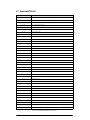
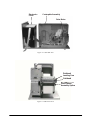
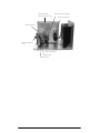
About This Manual ................................................................................................................................... 1
1.0
Introduction.................................................................................................................................. 1
2.0
General Maintenance................................................................................................................... 2
2.1 General Cleaning . . . . . . . . . . . . . . . . . . . . . . . . . . . . . . . . . . . . . . . . . . . . . . . . . . . . . . . . . . . . . . . . 2
2.2 Cleaning the Printhead. . . . . . . . . . . . . . . . . . . . . . . . . . . . . . . . . . . . . . . . . . . . . . . . . . . . . . . . . . . . 2
2.3 Cleaning the Platen Roller . . . . . . . . . . . . . . . . . . . . . . . . . . . . . . . . . . . . . . . . . . . . . . . . . . . . . . . . . 2
3.0
Parts Replacement....................................................................................................................... 3
3.1
3.2
3.3
3.4
4.0
Printhead. . . . . . . . . . . . . . . . . . . . . . . . . . . . . . . . . . . . . . . . . . . . . . . . . . . . . . . . . . . . . . . . . . . . . .
Mean Time to Repair (MTTR) . . . . . . . . . . . . . . . . . . . . . . . . . . . . . . . . . . . . . . . . . . . . . . . . . . . . . . .
Printhead Replacement . . . . . . . . . . . . . . . . . . . . . . . . . . . . . . . . . . . . . . . . . . . . . . . . . . . . . . . . . . .
Replacement Parts List . . . . . . . . . . . . . . . . . . . . . . . . . . . . . . . . . . . . . . . . . . . . . . . . . . . . . . . . . . .
Communications .......................................................................................................................... 7
4.1
4.2
4.3
4.4
Parallel Port . . . . . . . . . . . . . . . . . . . . . . . . . . . . . . . . . . . . . . . . . . . . . . . . . . . . . . . . . . . . . . . . . . . .
NIC (Network Interface Card) Adapter . . . . . . . . . . . . . . . . . . . . . . . . . . . . . . . . . . . . . . . . . . . . . . . .
Serial Port . . . . . . . . . . . . . . . . . . . . . . . . . . . . . . . . . . . . . . . . . . . . . . . . . . . . . . . . . . . . . . . . . . . . .
Communicating to RLWS Indicators . . . . . . . . . . . . . . . . . . . . . . . . . . . . . . . . . . . . . . . . . . . . . . . . .
4.4.1
4.4.2
4.4.3
5.0
3
3
3
4
7
7
7
8
Serial String . . . . . . . . . . . . . . . . . . . . . . . . . . . . . . . . . . . . . . . . . . . . . . . . . . . . . . . . . . . . . . . . . . . . . 8
Configuring Label Format in an RLWS Indicator . . . . . . . . . . . . . . . . . . . . . . . . . . . . . . . . . . . . . . . . . . 9
Gross Weight Label Format Example . . . . . . . . . . . . . . . . . . . . . . . . . . . . . . . . . . . . . . . . . . . . . . . . . 10
Specifications ............................................................................................................................ 11
SURVIVOR® SST2 Limited Warranty ....................................................................................................... 12
Technical training seminars are available through Rice Lake Weighing Systems.
Course descriptions and dates can be viewed at www.rlws.com or obtained by
calling 715-234-9171 and asking for the training department.
Copyright © 2004 Rice Lake Weighing Systems. All rights reserved. Printed in the United States of America.
Specifications subject to change without notice.
June 2004
ii
SURVIVOR SST2 Installation Manual
About This Manual
This manual is intended for use by technicians
responsible for servicing the SURVIVOR ® SST2
printer. Along with this manual, the Datamax ® I
Class T M Operator’s Manual (RLWS PN 75098)
accompanies the SST2 and covers operation,
calibration, and in-depth maintenance of the printer.
(The Datamax manual can also be viewed or
d ow n l o a d e d a t t h e R LW S d i s t r i bu t o r s i t e a t
www.rlws.com.)
The following service procedures are intended to
instruct you on how to:
• Understand features and specifications of the
SST2.
• Perform general printer maintenance.
1.0
Warning
Some procedures described in this
manual require work inside the printer
enclosure. These procedures are to be
performed by qualified service personnel
only.
Authorized distributors and their employees
can view or download this manual from the
Rice Lake Weighing Systems distributor
site at www.rlws.com.
Introduction
T h e S U RV I VO R ® S S T 2 l a b e l p r i n t e r i s a
high-performance, high speed industrial washdown
direct thermal and optional thermal transfer label
printer. Features include:
• Print speed of up to 8"-12" per second
(203.2mm/sec.).
• Common bar codes are resident in SST2
memory and can be printed with or without
adjacent human readable bar code
interpretations.
• Character fonts can be printed in any one of
four directions and with any one of nine
different font sizes. In addition, a resident
smooth font, called CG Triumvirate®, can be
separately selected and contain 10 different
font sizes. By using font multiplication, font
size expands vertically and horizontally up to
24 times.
• A dot-history control circuit, called SEAQTM
(Sequential Energy Adjustment for Quality),
enhances quality while printing at high
speeds. This circuit monitors the printed data
a n d a u t o m a t i c a l l y a d j u s t s t o p r ov i d e
maximum printhead performance. The 0.0049
inch print element prints high-density bar
codes and characters at a 203 dpi resolution.
In addition, the pixel size can be multiplied by
2 in the horizontal and 3 in the vertical
direction, producing larger formats.
• Connects to most computers and controllers
through either RS-232C or the Centronics®
parallel interface.
•
•
•
•
Optional memory cartridges of up to 4MB
font and 4MB Flash provide storage for fonts,
label formats and graphic images.
Optional Ethernet for network communication.
Software-selectable printhead temperature,
print speed, slew rates and form dimensions
provide the option of storing a wide variety of
parameters, thus eliminating the need for
manual adjustments. This is especially helpful
when using several different types or brands
of label stock, or when switching between
direct thermal printing and thermal transfer
printing.
Configurable for “one up” printing mode.
With the present sensor installed and enabled,
the next label is not printed until the last label
printed has been removed from the printer.
Quantities of one-at-a-time can be selected.
Introduction
1
2.0
General Maintenance
This section describes procedures for general
maintenance and cleaning of the SST2.
2.1
General Cleaning
During normal operation, media debris may
accumulate around the printer mechanism inside the
printer (see Figure 3-3 on page 6). This debris should
be removed regularly using a soft bristle brush and/or
vacuum cleaner.
2.2
Cleaning the Printhead
Foreign particles can collect on the printhead (see
Figure 3-2 on page 5), causing characters or bar codes
to appear light or faded. This type of problem is
evidenced by a continuous light streak which appears
in the same physical position on each printed line.
This condition should only appear after extensive
printer operation or if poor quality paper has been
used. It is recommended that Rice Lake Weighing
Systems-supplied labels are used to obtain continuous
high quality printing.
Recommended printhead cleaning intervals:
• Due to abrasion and foreign particle deposits,
direct thermal printheads should be cleaned
every 50,000 linear inches (12700m).
• Thermal transfer printheads should be cleaned at
least every 250,000 linear inches.
Printhead cleaning procedure:
1. Turn off and unplug printer from outlet.
2. Open cover. Unlock and raise printhead.
3. Gently wipe underside of printhead burn-line
area using a cotton swab moistened (not
soaked) with isopropyl alcohol. Allow to dry.
4. Lower and lock printhead.
5. Close cover. Plug in and turn on printer.
2
SURVIVOR SST2 Service Manual
2.3
Cleaning the Platen Roller
Use the following steps to clean the platen roller of the
SST2.
1. Turn off and unplug printer from outlet.
2. Open the cover. Unlock and raise the
printhead assembly.
3. Use a clean cotton swab or a lint-free cloth
dampened with isopropyl alcohol to wipe off
all debris from the platen roller. Manually
rotate the roller to clean the entire surface.
Allow to dry.
4. Lower the printhead assembly and lock into
position.
5. Close the cover. Plug in and turn on the
printer.
3.0
Parts Replacement
The following sections outline part replacement
guidelines and procedures, and list replacement parts
for the SURVIVOR® SST2 printer.
3.1
Printhead
The SST2 uses a thin film printhead that dissipates
heat faster than thick film, providing a longer head
life. Printhead warranty is 500,000 linear inches with
an expected life (using thermal transfer printing) of
2,000,000 linear inches.
3.2
Mean Time to Repair (MTTR)
Estimated MTTR the printer is less than 15 minutes. A
number of factors contribute to the ease of service.
Primarily, all electronics including the power supply
are located on a single plug-in circuit board. Most
electronic problems can be isolated and repaired with
a simple board swap.
The printhead is also designed for easy replacement.
One mounting screw and two locator pins eliminate
the mechanical head adjustments required of other
thermal label printers.
3.3
Printhead Replacement
Removal:
1. Turn the printer off and unplug from the
outlet. Open the media cover.
2. Loosen the printhead mounting screw.
Carefully unlatch the printhead assembly and
disconnect the two cables from the printhead.
Replacement:
1. Reconnect the printhead cables.
2. Position the printhead on the printhead
assembly and tighten the printhead mounting
screw.
Caution
Be sure to ground yourself to the
chassis before you remove or install the
printhead. This prevents a static
discharge from your body through the
printhead to the ground.
Parts Replacement
3
3.4
Replacement Parts List
Part Number
Description
53930
1.5" media hub assembly
53934
Flanged .375 ID x .875 OD bearing
53951
Standard cutter cable assembly
72238
Motor control cable assembly
72198
PH data cable assembly
72190
PH power cable assembly
72176
Front panel flex cable
72177
Media sensor flex cable
72237
P/S power cable
53933
Cap-Cam
53931
Media clutch assembly
53929
Ribbon clutch assembly
34911
E-ring 3/8 Truarc 5133-37
53935
24 pitch 48 teeth gear spur Delrin
53936
Gear spur Delrin, 24 teeth
53952
2 x 20 character LCD module
53955
Main board, SST2 12 ips
53940
Media sensor assembly
53928
Media take-up assembly
53909
Peel mechanism
53943
Peel/present sensor assembly
53924
Platen assembly
53923
Post idler
53942
Present sensor assembly
53939
Printhead 203 dpi dual connector
53926
Ribbon spool assembly
67797
Cover ribbon spool
53954
RS 485/RS 422, IC Trnsver, 14 pin dip
53938
Torsion spring
53941
Stepper motor assembly
53927
Ribbon supply assembly
53925
Take-up hub assembly
53937
Timing belt
72054
SST2 overlay
72053
Cover plate
74705
Base gasket
74706
Coverplate gasket
74810
Shroud gasket
80756
Main board, SST2 8 ips
Table 3-1. SURVIVOR® SST2 Replacement Parts List
4
SURVIVOR SST2 Service Manual
Electronics
Cover
Centerplate Assembly
Drive Motor
Figure 3-1. SST2 Side View
Printhead
Printhead
Printhead
Leveling
Cam
Leveling
LevelingCam
Cam
Printhead
Printhead
Printhead
Peel/Present
Peel/Present
Peel/Present
Assembly
Option
Assembly
Option
Assembly
Option
Figure 3-2. SST2 Front View
Parts Replacement
5
Thermal Transfer
Assembly Cover Plate
Media Rewind Assembly
Print Mechanism
Printhead Release
Lever
Options Connector
Media Guide
Media Sensor
Figure 3-3. SST Side View
6
SURVIVOR SST2 Service Manual
Media Supply Hub
4.0
Communications
Using a data detection process, the interface selection occurs automatically in the printer. At power-up, the
printer begins monitoring the interface ports for activity. When the host transmits data, the printer port detecting
this data is set active and remains active as long as data flow continues. Once the incoming (received) data flow
stops and the host timeout value is exceeded, the detection process is repeated. Should the data flow stop before a
complete label format is received, the format is ignored and must be sent to the printer again.
NOTE: To change an active port immediately, cycle the printer power off and on.
4.1
Parallel Port
The parallel interface has two menu-selectable modes of operation: uni-directional or bi-directional. The
uni-directional mode supports forward channel only communication and requires Centronics® cable with a
36-pin male connector.
The bi-directional mode supports forward and reverse channel IEEE 1284 Compliant communications. Data can
be returned to the host in this mode provided it has compliant hardware, supporting software and is connected to
the printer via an IEEE 1284 Compliant cable with a Centronics 36 pin male connector.
4.2
NIC (Network Interface Card) Adapter
The optional NIC adapter has several menu-selectable modes (see Datamax® Manual, PN 75098). The following
LED indicators on the NIC adapter provide operational information:
• LINK: A green LINK LED indicates a good physical connection to the network.
• ACT: The ACT LED (activity) flashes green or red when the server is ready for use; green indicates
activity for this IP address while red indicates collisions on the network.
• 100: A green 100 LED indicates a 100 BASE-T (100 MB) network connection.
The following buttons are accessible from the back of the printer:
• TEST: Causes an NIC configuration label to print.
• ETHERNET RESET: Resets the NIC adapter.
NOTE: Following initialization, the printer indicates READY. However, the NIC adapter is not ready to receive data until
its boot-up process is completed. Depending upon the NIC adapter configuration, this process may take up to two
minutes to complete.
4.3
Serial Port
The serial interface supports RS-232C and, if equipped, RS-422 communications. The following list of serial
port settings is menu-selectable and must match the host computer’s serial port settings.
• Baud rate (serial communication speed)
• Word length
• Word parity
• Number of stop bits
• Handshaking protocol
In addition to the port settings, the serial interface cable wiring must have specific connections (pin-outs) for
proper data exchange between the host and printer. The different serial cable pin-outs and suggested applications
are shown in Figure 4-1 on page 8.
Communications
7
PC (DB9P) to Printer
Null Modem (MXM)
PRINTER
HOST
1
TXD 2
RXD 3
7
SHIELD
1
3 RXD
2 TXD
GROUND
7
PC
1
TXD 3
RXD 2
PRINTER
SHIELD
1
3 RXD
2 TXD
20 BUSY
CTS 8
5
GROUND
7
4
4 RTS
6
4 RTS
5
5 CTS
4
5 CTS
DB25P
DB25P
For connection to other DCE equipment.
Flow control is only Xon/Xoff.
PC (DB25P) to Printer
PC
1
TXD 2
RXD 3
SHIELD
7
GROUND
RS-422 Connection
PRINTER
HOST
1
3 RXD
2 TXD
RXD+
RXDTXD+
TXD-
20 BUSY
CTS 5
DB9S
DB25P
For connection to a PC compatible with
DB9P communication ports. Flow control
can be either Xon/Xoff or CTS/DTR.
PRINTER
9 TXD+
10 TXD18 RXD+
19 RXD-
7
4
6
4 RTS
5
8
5 CTS
DB25P
20
DB25P
DB25S
For connection to a PC compatible with
DB25 communication ports. Flow control
can be either Xon/Xoff or CTS/DTR.
Figure 4-1. Serial Interface Cable Pin-outs
4.4
Communicating to RLWS Indicators
To communicate from an RLWS indicator directly to the SST2, a change to the standard RS-232 output is
required. The indicator must have Smart SerialTM communication or a custom serial format developed.
NOTE: The following sections do not apply to the IQ plus® 310A indicator as it does not feature Smart Serial
communication or custom serial format.
4.4.1
Serial String
To develop the correct serial string, you first need to understand the Datamax® Programming Language (DPL)
serial string. For every piece of information printed, the print format record must consist of the following three
pieces of information:
• A header that is fifteen characters long. The header specifies which font is used and where the data is
printed.
• Data to print.
• Termination character (such as a carriage return).
8
SURVIVOR SST2 Service Manual
Header
A typical DPL serial string header consists of the following pieces of information:
Data
STX
Definition
Description
Start of text
Must have start of text at beginning of character stream
Label
Designation of label
Character rotation
Rotation of characters
_
Font
Font choice
_
Horizontal rotation
Horizontal (width) muliplier
_
Vertical rotation
Vertical (height) multiplier
000
Bar code
Dependant on type of bar code selected
• If printing graphics, lines, boxes, and human-readable fonts 0 through 8,
these three characters are ignored, but they still must be sent to the printer as
000.
• For human-readable font 9, these three characters must be a number from
001 to 010 to select a font size for the CG triumvirate smooth font. Other
selections are available if downloading from RAM, flash memory modules,
ROM font modules.
• For bar code fonts, these three characters represent a bar code height
number. Numbers ranging from 001 (or 0.01 inch) to 999 (or 9.99 inches).
1250
Row address
Four characters are the vertical offset in hundredths of an inch
0200
Column
Four characters are the horizontal offset in hundredths of an inch
L
1–4
Table 4-1. Serial String Header
Data String, Carriage Return and Execute Command
After the header, a data string and a carriage return are needed for each item to be printed.
Data
TEXT
CR
E
Definition
Description
Printed information (data
string)
Data to be printed (limited by range of printhead). Data string is terminated by a
carriage return
Carriage return
Carriage return terminates data string
Execute
At end of label data information, execute signals the end of the label to the printer
Table 4-2. Data String, Carriage Return and Execute Command
4.4.2
Configuring Label Format in an RLWS Indicator
Use the following steps to configure label format in an RLWS indicator:
1. Determine the operation mode in which you are printing. This step is important to make sure the correct
format is stored in gross, net or other format modes available in the indicator.
2. Create the format.
Communications
9
4.4.3
Gross Weight Label Format Example
The following is a format string example for a gross weight label configured in an RLWS indicator.
2 76 60 78 76 62 49 51 49 49 48 48 48 48 49 48 48 48 48 53 48 60 71 62 60 78 76 62 69
STX L < N L > 1 3 1 1 0 0 0 0 1 0 0 0 0 5 0 < G > < N L > E
Figure 4-2. Simple Gross Weight Data Stream/ASCII Example
10000 LB
Figure 4-3. Simple Gross Weight Label Example
10
SURVIVOR SST2 Service Manual
Key In
Data Stream
5.0
Specifications
Printing
Type
Print Speed
Resolution
Minimum Dot Size
Optional Dot Sizes
Resident Fonts
Character Display
Bar Codes
Switches
Direct thermal or optional thermal
transfer
2" – 12" per second (51mm – 304mm)
2" – 8" per second, SST2
in .5" programmable increments
203 dpi (8 dots/mm)
0.005" (0.127mm) square
0.010" (0.254mm); 0.015" (0.381mm)
vertical, 0.010" (0.254mm) horizontal
Ten alphanumeric fonts from 0.035" H
– 0.64" H (0.89mm – 16.26mm)
including OCR-A, OCR-B (size and
character set III), and a CG Triumvirate
scalable font
33.83 cpi FONT 0 at 1X, .70 cpi FONT
6 at 8X
Code 39, UPC-A, UPC-E, Interleaved
2 of 5, Code 128, EAN-8, EAN-13,
HIBC, Cadabar, Plessey, UPC 2 and 5
digit addendums, Code 93, Postnet,
UCC/EAN Code 128, Telepen, UPS
MaxiCode, FIM, PDF417, USD-8,
Datamatrix, QR Code, Aztex, TLC 39,
Micro PDF417, RSS
Media
Width
Length
Thickness
Type
Supply Roll Capacity
Capacity in Rewind
Mode
Label Material
Thermal Transfer
Ribbon
1.0" – 4.65" (25.4mm – 118mm)
0.25" – 99" (6.35mm – 2514.6mm) at
100 dots per inch
0.0025" – .010" (0.0635mm –
0.254mm)
Roll-fed, die-cut labels, tags, tickets,
continuous forms with blackstripe
sensing
8" (203mm) maximum outside
diameter on standard 1 or 3" (25.4 or
76mm) core. 6250" lineal stock,
0.0065" thick
5" (127mm) maximum outside
diameter on internal rewind spindle
1.5" core (38mm). 2100" lineal stock,
0.0065" thick
Thermal transfer plain-coated papers,
vinyl, Mylar, metalized paper,
non-woven fabric, fine woven fabric,
thermal-visible light-scannable paper,
infrared scannable paper, thermal
ticket/tag stock, thermally sensitive
plastic stock
Black or colored inks; 360 meters
long, 4.6 microns, backcoated, ±10%
label width. 1968 feet (600 meters)
max
Switches
CANCEL, PAUSE, and FEED. Variable
Head Temperature Control
Communications Interfacing
Parallel and IEEE
RS-232C
2400, 4800, 9600, 19.2K, 28,800, or
38.4K baud
Character Set
ANSI ASCII character set.
Word Length
Selectable 7 or 8 bit data format
Handshaking
XON/XOFF (on receive mode only) and
CTS/DTR
Input Buffer
Approximately 7000 bytes; XOFF is
transmitted and DTR goes low when
60 bytes are available in the buffer.
XON is transmitted and DTR goes high
when 1000 bytes are left in the buffer
Characters transmitted with no parity from the printer
Electrical
Input Voltage
90 - 264 VAC, 47 -63 Hz
Note: The socket outlet should be installed near the
equipment and be easily accessible
Circuit Protection
At 115V = 1.5A Slo Blo
Grounding
Unit must be connected to a properly
grounded receptacle
Power Consumption 90 watts (standby - 10 watts)
UL Listed
Type 4X for indoor use only
Memory Modules
Internal Memory
Module
PCB without fonts
FONT/FLASH modules
4 MB addressable
Font Modules
Font Modules
Range of Fonts
Eight available
ILPC, Kanji Simplified Chinese and I/O
Expansion Board
Environmental
Operating
Temperature
Humidity
Ventilation
Dust
Electromagnetic
Radiation
40°F – 95°F (4°C – 35°C)
10% – 95% non-condensing
Free air movement
Nonconducting, non-corrosive
Moderate RF fields can be tolerated
Mechanical
Size
Weight
13.75" H x 14.125" W x 25.25" D
(349.3mm H x 358.8mm W x
641.4mm D)
Approximately 63 lb (28.6 kg)
Specifications
11
SURVIVOR® SST2 Limited Warranty
Rice Lake Weighing Systems (RLWS) warrants that all RLWS equipment and systems properly installed by a
Distributor or Original Equipment Manufacturer (OEM) will operate per written specifications as confirmed by
the Distributor/OEM and accepted by RLWS. All systems and components are warranted against defects in
materials and workmanship for one year.
RLWS warrants that the equipment sold hereunder will conform to the current written specifications authorized
by RLWS. RLWS warrants the equipment against faulty workmanship and defective materials. If any equipment
fails to conform to these warranties, RLWS will, at its option, repair or replace such goods returned within the
warranty period subject to the following conditions:
• Upon discovery by Buyer of such nonconformity, RLWS will be given prompt written notice with a
detailed explanation of the alleged deficiencies.
• Individual electronic components returned to RLWS for warranty purposes must be packaged to
prevent electrostatic discharge (ESD) damage in shipment. Packaging requirements are listed in a
publication, Protecting Your Components From Static Damage in Shipment, available from RLWS
Equipment Return Department.
• Examination of such equipment by RLWS confirms that the nonconformity actually exists, and was
not caused by accident, misuse, neglect, alteration, improper installation, improper repair or
improper testing; RLWS shall be the sole judge of all alleged non-conformities.
• Such equipment has not been modified, altered, or changed by any person other than RLWS or its
duly authorized repair agents.
• RLWS will have a reasonable time to repair or replace the defective equipment. Buyer is responsible
for shipping charges both ways.
• In no event will RLWS be responsible for travel time or on-location repairs, including assembly or
disassembly of equipment, nor will RLWS be liable for the cost of any repairs made by others.
THESE WARRANTIES EXCLUDE ALL OTHER WARRANTIES, EXPRESSED OR IMPLIED, INCLUDING WITHOUT
LIMITATION WARRANTIES OF MERCHANTABILITY OR FITNESS FOR A PARTICULAR PURPOSE . N EITHER
RLWS NOR DISTRIBUTOR WILL, IN ANY EVENT, BE LIABLE FOR INCIDENTAL OR CONSEQUENTIAL DAMAGES.
RLWS AND BUYER AGREE THAT RLWS’S SOLE AND EXCLUSIVE LIABILITY HEREUNDER IS LIMITED TO
REPAIR OR REPLACEMENT OF SUCH GOODS. IN ACCEPTING THIS WARRANTY, THE BUYER WAIVES ANY AND
ALL OTHER CLAIMS TO WARRANTY.
SHOULD THE SELLER BE OTHER THAN RLWS, THE BUYER AGREES TO LOOK ONLY TO THE SELLER FOR
WARRANTY CLAIMS.
NO TERMS, CONDITIONS, UNDERSTANDING, OR AGREEMENTS PURPORTING TO MODIFY THE TERMS OF THIS
WARRANTY SHALL HAVE ANY LEGAL EFFECT UNLESS MADE IN WRITING AND SIGNED BY A CORPORATE
OFFICER OF RLWS AND THE BUYER.
© 2004 Rice Lake Weighing Systems, Inc. Rice Lake, WI USA. All Rights Reserved.
RICE LAKE WEIGHING SYSTEMS • 230 WEST COLEMAN STREET • RICE LAKE, WISCONSIN 54868 • USA
12
SURVIVOR SST2 Service Manual