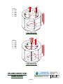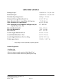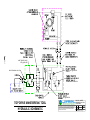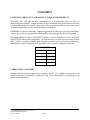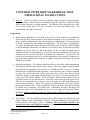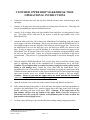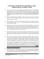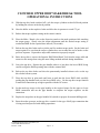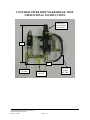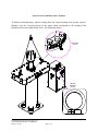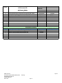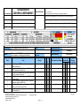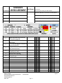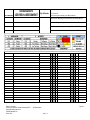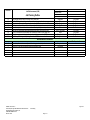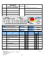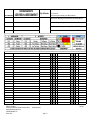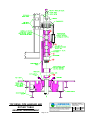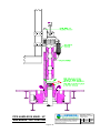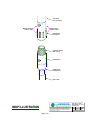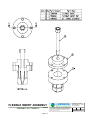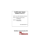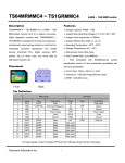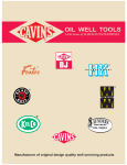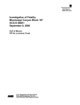
1
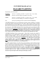
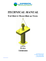
TECHNICAL MANUAL
TOP DRIVE MAKE BREAK TOOL
covers
MODEL
TDMB2000
4225 Highway 90, East
Broussard, Louisiana 70518
Phone: (337) 837-8847
Fax: (337) 837-8839
www.superior-manf.com
Published 02/2005
8 Copyright, 2005, SUPERIOR Manufacturing & Hydraulics, Inc. All rights reserved. This document is
the property of SUPERIOR Manufacturing & Hydraulics, Inc. It is supplied as reference information to
users of our products. This document is considered confidential and is not to be disclosed, copied or
reproduced, transmitted, transcribed in any form or stored in any type of system without the express
written consent of SUPERIOR Manufacturing & Hydraulics, Inc.
CLINCHER, LOCKJAW & Grit Faced Die are trademarks of SUPERIOR Manufacturing & Hydraulics, Inc.
The products described in this manual are covered by U.S. and foreign Patents and/or pending Patent
Applications.
This manual is not a controlled document and is subject to
revision without notice. To receive updates and insure you
have access to the latest information concerning the
CLINCHER Make/ Break Tool, we request you complete
this form and return the lower half to SUPERIOR
Manufacturing and Hydraulics by mail or facsimile. Access
to our manuals can also be acquired through our web site
www.superior-manf.com. Click the tab ‘CLINCHER Products’,
click the equipment from the list to get Specs page, click the
tab ‘Download Manual’.
Name:
Company:
Address:
Address:
City:
Postal Code:
Telephone:
State:
Country:
Fax:
Make/Break Model No.:
Assembly Date:
Serial No.:
CLINCHER Make/Break Tool Technical Manual Registration Form
Name:
Company:
Return To:
Address:
Address:
City:
Postal Code:
Telephone:
Make/Break Model No.:
Assembly Date:
SUPERIOR Mfg. & Hyd.
4225 Hwy. 90 East
Broussard, LA 70518
USA
Country:
Fax:
Serial No.:
Telephone: 337-837-8847
Facsimile: 337-837-8839
Web Site: www.superior-manf.com
TABLE OF CONTENTS
Hazard Warnings
1
Description, Features, & Specifications
2
Schematics
3
Assembly
4
Pre-Order Considerations
Operational Instructions & Illustrations
Job Risk Assessment Forms
Installation & Make Up, Break Out & Removal
5
Maintenance Instructions & Trouble Shooting
6
Spare Parts Recommendations
7
Make/Break Tool Illustrations
8
Valve Technical Data
9
CLINCHER MAKE/BREAK TOOL
REVISION TABLE
Section
Cover
2
8
Page
Cover
1-2
1-3, 4.1,
6
2
7
Date
02/2005
Description
Changed illustrations to show new lower extension assembly.
02/2005
Added illustration TDMB2040 Lower Extension Assembly. Revised illustration Make/Break Tool Assy. to show TDMB2040 Lower Extension Assy.
Revised illustration TDMB1036 Air Booster Panel.
04/18/05 Revised Specs-Makeup Torque from 110,000 ft/lbs to 130,000 ft/lbs.
SUPERIOR Manufacturing & Hydraulics, Inc.
CLINCHER Make/Break Tool TDMB2000
Revision: 04/05
Page 0 - 1
CLINCHER Make/Break Tool
HAZARD WARNING
Nomenclature used in this manual:
WARNING
concerns an operating procedure or practice that, if not strictly
observed, can result in injury to personnel or loss of life.
Caution
concerns an operating procedure or practice that, if not strictly
observed, can result in damage to or destruction of equipment.
Note
concerns an operating procedure or practice that needs highlighting.
CLINCHER Make/Break Tools are manufactured to provide a means of making up or breaking
out high torque tubular connections between Varco TDS3, TDS4 & TDS5 Top Drives and their
upper internal blowout preventer (IBOP) valves. This tool utilizes high pressure hydraulic fluid
power which can cause the tool to move suddenly and with great force if it is not properly rigged
up and operated. CLINCHER Make/Break Tools contain rotating and reciprocating parts which
can severely or fatally injure personnel who are operating, repairing, or near this equipment
during its operation. WARNING: Make/Break Tools are not to be operated by untrained
personnel or per-sonnel with diminished physical or mental capacity. No work of any type is
to be carried out while the Make/Break Tool is connected to any hydraulic power unit.
CLINCHER Make/Break Tools are heavy tools. When lifted vertically, they should be
suspended from a secure, high strength 5/8" IWRC minimum diameter wire cable with a 20.6 ton
minimum breaking strength. The wire cable should be hung as close to the center of the
wellbore as possible, without interfering with drilling equipment operation, to allow the tool to
be readily swung into the working position. WARNING: Users must insure the entire lifting
system including cables, rig mounting points, lift cylinders, lifting brackets/bridles,
winches, pulleys, counter weights, etc., are capable of handling the static weight of the tool
PLUS any shock loads which may be seen during operation.
A 2" IWRC minimum diameter wire cable with a 198 ton minimum or better breaking strength,
should be attached at a 90 degree angle to the Make/Break Tool and at the same level to insure
proper readout of optional external torque indicator. If optional external torque indicator is used,
the rotary table must be unlocked and free to rotate. A SNUBBING LINE should always be
attached to provide additional safety in the event of a rotary table lock slippage. WARNING:
Users must provide a means of safely controlling the Make/Break Tool movements in all
directions when it is in use. Failure to account for its size, weight, movement and the
amount of torque developed could result in personnel injury or death.
SUPERIOR Manufacturing & Hydraulics, Inc.
CLINCHER Make/Break Tool
Revision: 09/04
Page 1 - 1
CLINCHER Make/Break Tool
HAZARD WARNING
CLINCHER Make/Break Tools utilize high pressure hydraulic fluids. Portions of the tool,
control valves, hydraulic lines and cylinders may contain high pressure fluid even when the
power unit is de-energized and the fluid supply hoses are disconnected. During normal operation
the temperature of the hydraulic fluids as well as hoses, piping, valves, etc., can rise to a level
which can cause burns. WARNING: Personal protective gear including safety glasses, face
shields, protective gloves and protective clothing must be worn to guard against the
hazards of high pressure fluids. Tight fitting clothing is required to prevent entanglement
in rotating components. These tools should be serviced by thoroughly trained and
qualified hydraulic technicians using procedures to safely insure hydraulic pressure is bled
from these circuits.
No attempt should be made to operate the CLINCHER Make/Break Tool for any purpose other
than which it is intended. This system is capable of generating very large torsional loads which
if improperly applied or controlled, could result in damage to the tubular, to the tool or could
possibly result in injury or death of personnel. Do not attempt to operate the unit without correct
dies and the proper size tubular being in the tool.
SUPERIOR Manufacturing & Hydraulics, Inc.
CLINCHER Make/Break Tool
Revision: 09/04
Page 1 - 2
CROSS
GENERAL INFORMATION
HYDRAULIC PRODUCT
SAFETY
HYDRAULIC PRODUCT SAFETY
WARNING: Valve lever (spool) may "stick" (not center) under
certain conditions allowing the hydraulic equipment to continue to
operate and could cause serious injury, death or equipment failure.
VALVE SAFETY: Read and follow instructions carefully. Failure to observe instructions
and guidelines may cause serious injury, death or equipment failure. A sticking valve
(spool bind) may be caused by one or more of the following factors:
DIRTY OIL: Oil must be filtered to a minimum of 25 microns. Filters should be changed regularly spin-on types after 50 hours of initial use and then after every two hundred fifty hours of use. Use of
a condition indicator is recommended. Consult your tractor or implement owner’s manual for filtration and changing recommendations for internal systems.
OIL REQUIREMENTS: Premium quality anti-wear type oil with a viscosity between 100 and 200
SSU at operating temperatures. Certain synthetic oils may cause spool seals to swell and the valve
to stick. If in doubt, call CROSS Engineering.
IMPROPER HOOK UP OR MOUNTING: Always use the proper size fittings. Hook up "in" & "out"
as noted on the valve body. Do not overtorque pipe fittings. Mounting surfaces should be flat and
care should be used when tightening mounting bolts. Over-tightened bolts can cause spool bind
and casting breakage. When hooking a valve in series, always use a power beyond sleeve. Consult your tractor or implement manual to make sure you have the proper quick disconnect line
connected to the inlet of the remote valve.
MISAPPLICATION: Always use the proper valve for the job. CONVERTA, CD, CS or CA valves
should never be used for metered heavy load lifting - loaders or similar applications. Use an open
center valve for open center applications and a closed center valve for closed applications. If in
doubt, check with your tractor dealer. Contact CROSS if the valve allows the hydraulic equipment to
creep excessively.
MAINTENANCE: Make sure all bolts are tightened and torqued to the recommended specification.
Bent or broken parts should not be used. Replace immediately. Always use exact replacements.
Always protect valve spool from paint overspray.
Faulty quick disconnects can cause high back pressures and sticking spools. Check quick disconnects periodically to make sure they are functioning properly. If valve spool does not center or
appears to stick, do not use!
PUMPS & MOTORS SAFETY:
A relief or bypass in your hydraulic system is necessary to prevent pump from breakage due to
overpressurization. Use correct fittings and proper oil as noted in the technical service manual
packed with each unit. Change oil as recommended by your implement or tractor manufacturer.
CYLINDER SAFETY:
Check clevis clearances before, during and after extending the cylinder and before using the cylinder
under pressure to avoid possible injury, or bent or broken rods caused by binding. Never operate
a cylinder above recommended pressures. Never use a cylinder as a safety device when transporting equipment.
PINHOLE LEAKS:
If you observe a pinhole leak, discontinue use of the component. If oil has penetrated your skin or
contacted your eye, seek medical attention immediately!
SLING ASSEMBLY
P/N TDMB1025
BREAK OUT
MAKE UP
CONTROL
CONSOLE
P/N: TDMB2036
DRIVE SUB
TOP DRIVE
MAKE/BREAK TOOL
P/N: TDMB 2000
POSITION
INDICATOR
EXTENSION
LOCKING DRIVE PIN
PUBLISHED 02/2005
Page 2 - 1
4225 Highway 90, East
Broussard, Louisiana 70518
Phone: (337) 837-8847
Fax: (337) 837-8839
www.superior-manf.com
63"
20 1/2"
32 1/2"
21"
10 1/8" MIN ID
THRU TOOL
76 1/8"
MAX ALLOWABLE
TOOL JOINT HEIGHT
106 7/8"
110 7/8"
19"
MIN ID
41 7/8"
DIMENSIONAL VIEWS
4225 HWY. 90 EAST
BROUSSARD, LA 70518
(318) 837-8847
THIS DOCUMENT IS THE PROPERTY OF SUPERIOR MANUFACTURING &
HYDRAULICS AND IS CONSIDERED CONFIDENTIAL. THIS INFORMA TION
MAY NOT BE USED, DISCLOSED, COPIED, OR REPRODUCED IN ANY
FORM, WITHOUT THE EXPRESS W RITTEN CONSENT OF SUPERIOR
MANUFACTURING & HYDRAULICS.
1
REV. #
LOG #
02/23/05
DATE
REF: S:\Equip Manuals\Dwgs\
TDMB2000\Dimensions rev1.wpg
MAKE/BREAK
BEZEL RING
PRESUURE/
MAKE/BREAK
TORQUE GAUGES
ISOLATION VALVE
MAKE UP PRESSURE
CONTROL VALVE
MAKE/BREAK
DIRECTIONAL
CONTROL VALVE
MAKE/BREAK CONTROL CONSOLE
DIMENSIONAL VIEWS
ASSEMBLY NO. TDMB2020
4225 HWY. 90 EAST
BROUSSARD, LA 70518
(318) 837-8847
THIS DOCUMENT IS THE PROPERTY OF SUPERIOR MANUFACTURING &
HYDRAULICS AND IS CONSIDERED CONFIDENTIAL. THIS INFORMATION
MAY NOT BE USED, DISCLOSED, COPIED, OR REPRODUCED IN ANY
FORM,WITHOUT THE EXPRESS WRITTEN CONSENT OF SUPERIOR
MANUFACTURING & HYDRAULICS.
REV. #
LOG #
12/16/04
DATE
REF: S:\Equip Manuals\Dwgs\
TDMB2000\Console Dimen.wpg
B
A
6 KEYS
A: 0.750
B: 0.313
C: 9.125
D: 9.750
E: 8.500
F: 10.500
G: 6.531
D
C
E
F
G
PH85 DRIVE SUB
A
8 KEYS
A: 0.750
B: 0.325
C: 7.875
D: 8.525
E: 8.500
F: 10.500
G: 6.531
B
D
C
E
F
G
PH60 DRIVE SUB
4225 HWY. 90 EAST
BROUSSARD, LA 70518
(318) 837-8847
SPLINED DRIVE SUB
DIMENSIONS
THIS DOCUMENT IS THE PROPERTY OF SUPERIOR MANUFACTURING &
HYDRAULICS AND IS CONSIDERED CONFIDENTIAL. THIS INFORMATION
MAY NOT BE USED, DISCLOSED, COPIED, OR REPRODUCED IN ANY
FORM,WITHOUT THE EXPRESS WRITTEN CONSENT OF SUPERIOR
MANUFACTURING & HYDRAULICS.
Page 2 - 4
REV. #
LOG #
09/16/04
DATE
REF: S:\Equip Manuals\Dwgs\
TDMB1000-01\Drive Sub.wpg
DESCRIPTION and APPLICATION
The CLINCHER® RF (Rig Floor) Make/Break Tool is manufactured to service upper internal
blow-out preventer valves associated with Varco TD3S, TD4S and TD5S top drives. This
compact hydraulically operated tool generates a minimum of 110,000 ft/lbs of make-up torque
and 130,000 ft/lbs of break-out torque when used with a 2000 psi hydraulic power supply (not
included). Each cycle will generate 45 degrees of rotation.
The RF Make Break Tool’s upper flanged hub allows a variety of accessories to be bolted in
place to satisfy rig floor torquing needs. The bottom of the RF Make/Break Tool accepts pins
which engage a 27 1/2" or 37 1/2" API Rotary Table Kelly Drive System per API 7K (other
configurations upon request). The bottom is also flanged to accept a lower extension or
accessories which are available to allow the bottom side to directly grip tubulars.
The RF Make/Break Tool is provided with an Upper Extension with flanged connections
compatible for the tool and drive subs for Varco PH60 and PH85 Pipe Handlers’ upper extension
BOP valve. Approximate overall length is 20 1/4". The Extension OD of 7 1/4" is for compatibility with ring tongs. The drive sub maximum OD is 14", minimum ID is 6.65" and OAL is
10.5". Customer will need to specify if the RF Make/Break Tool is to be used with Varco PH60
or PH85 Pipe Handler.
The RF Make/Break Tool is provided with a Lower Extension with a flanged connection to raise
the Make/Break Tool 54" above the Rotary Table. This extension offers a 19" ID to
accommodate drillpipe tool joints suspended by rotary slips. Slip handles must be removed
before landing Make/Break Tool and Extension.
The RF Make/Break Tool is provided with two torque drive subs and two lockdown drive subs.
Lockdown drive subs feature CLINCHER® grit face coating to engage sockets without
requirement for modifications. Drive subs may be attached directly to the bottom of the RF
Make/Break Tool or to the bottom of the RF Make/Break Lower Extension.
The RF Make/Break Tool is also provided with a separate free standing hydraulic control
console. The console is provided with quick disconnects for supply, return and work circuits. It
includes a directional control valve for make/break connections and includes a gauge which
allows monitoring of make/break torques and pressures. An adjustable pressure control valve
allows the operator to regulate the amount of make-up torque developed. This control system is
set up for closed style pressure compensated hydraulic power systems with pressures up to 3,000
psi. Control valves for open hydraulic systems are available upon request. System includes
Haskel MAA gas booster, 3-way air valve, and air regulator to boost top drive braking force
(installed by others).
A Handling Sling with welded padeyes features two 1/2" 6x19 IWRC galvanized cables 48" long
with swaged open socket on lower ends for pinning to two padeyes welded to the upper
extension tube. The upper end of the cables are looped through a 1" sling link and feature
galvanized thimbles with swaged retaining sleeves. Sling is proof tested and equipped with a
metal tag.
SUPERIOR Manufacturing & Hydraulics, Inc.
CLINCHER Make/Break Tool
Revision: 01/05
Page 2 - 5
DESCRIPTION and APPLICATION
Two 3/4" x 10' long two-wire hydraulic hoses with 2,500 psi working pressure are provided to
connect control console to RF Make/Break Tool. These have a braided fabric protective cover to
guard against abrasion. They are equipped with a 3/4" male NPT x 3/4" female JIC swivel hose
ends.
Two 3/4" x 20' long standard two-wire hydraulic hoses with 2,500 psi working pressure are
provided to connect control console to rig’s hydraulic power loop. They are equipped with a
3/4" male NPT x 3/4" female JIC swivel hose ends.
An optional storage base incorporating the control console, pressure/torque gauge, torque control
valve, and quick disconnects associated with hydraulic control console. This storage base is
fabricated using 6"-17.25 PPF carbon steel S-beams and 1/2" flat plate. The plate contains
openings for torque drive subs and lockdown drive subs. Hold downs are provided to lock RF
Make/Break Tool to storage base during transit. Storage base features provisions for handling
using forklift or four part sling (not included).
SUPERIOR Manufacturing & Hydraulics, Inc.
CLINCHER Make/Break Tool
Revision: 09/04
Page 2 - 6
SPECIFICATIONS
Makeup Torque 1
130,000 ft.lbs. / 176,256.6 Nm
Breakout Torque 1
130,000 ft.lbs. / 176,256.6 Nm
Maximum Operating Pressure
2,000 psi / 137.9 bar
Minimum ID through Make/Break Tool
10 1/8" / 25.7 cm
Upper Extension OD for compatibility with rig tongs
Upper Extension OAL (approximate)
7 1/4" / 18.4 cm
20 1/4" / 51.4 cm
Lower Extension ID to accommodate drill pipe tool joint
suspended by rotary slips
19" / 48.26 cm
Drive Sub Maximum OD
Drive Sub Minimum ID
Drive Sub OAL
14.0" / 35.6 cm
6.65" / 16.9 cm
10.5" / 26.7 cm
Overall Length Make/Break Tool
30 5/16" / 77.0 cm
Overall Width Make/Break Tool
68 1/2" / 174.0 cm
Overall Height Make/Break Tool w/o Sling
106 7/8" / 271.5 cm
Weight (approximate)
3,540 lbs. / 1,605.7 kg
1
Torque ratings are based upon 2,000 psi operating pressure.
Standard Equipment:
- Handling sling
- Control console
- Hoses to connect control console to Make/Break Tool
- Hoses to connect control console to hydraulic power loop
SUPERIOR Manufacturing & Hydraulics, Inc.
CLINCHER Make/Break Tool
Revision: 04/05
Page 2 - 7
INLET RELIEF VALVE
SET @ 2500 PSI
ISOLATION BALL VALVE
SET @ 2500 PSI
ADJUSTABLE TO 2500 PSI
SET @ 2500 PSI
4225 HWY. 90 EAST
BROUSSARD, LA 70518
(318) 837-8847
TOP DRIVE MAKE/BREAK TOOL
HYDRAULIC SCHEMATIC
THIS DOCUMENT IS THE PROPERTY OF SUPERIOR MANUFACTURING &
HYDRAULICS AND IS CONSIDERED CONFIDENTIAL. THIS INFORMATION
MAY NOT BE USED, DISCLOSED, COPIED, OR REPRODUCED IN ANY
FORM,WITHOUT THE EXPRESS WRITTEN CONSENT OF SUPERIOR
MANUFACTURING & HYDRAULICS.
REV. #
LOG #
01/12/05
DATE
REF: S:\Equip Manuals\Dwgs\
TDMB2000\Sche matic.wpg
Item Qty.
BRAKE
MECHANISM
14
TOP DRIVE
MOTOR SHAFT
11
185 psi
17
19
EXHAUST
15
16 13
Part No.
Description
1
1
1/4 MRO
1/4" MALE RUN TEE
2
2
3/8 FF
3/8" MALE PIPE NIPPLE
3
2
3/8 MMS
MALE BRANCH TEE 3/8" MNPT X 3/8" FNPT
4
2
3/8 MRO
3/8" MALE RUN TEE
5
1
3/8 X 1/4 FG
3/8" NPT X 1/4" NPT EXPANDER/ADAPTER
6
2
3/8 X 1/4 PTR
3/8" NPT X 1/4" NPT PIPE THREAD REDUCER
7
1
4 FTX
MALE CONNECTOR 1/4" MJIC X 1/8" MNPT
8
1
4-4 FTX
1/4" MNPT X 1/4" MJIC STRAIGHT
9
2
6 FTX
1/4" MNPT X 3/8" MJIC MALE CONNECTOR
10
2
6-6 CTX
MALE ELBOW 3/8" MJIC X 3/8" MNPT
11
1
9889K19
AIR POP OFF VALVE 185 PSI, 1/4" NPT
12
1
1478
BALL VALVE BRASS, 3/8" FNPT
13
1
B18-02-FK00
AIR FILTER/ REGULATOR 1/4" NPT PORTS
14
1
BAC-600-25
GAUGE 600# 2 1/2" DIA BRASS
15
1
CM4554
3/8" CHECK VALVE
16
1
GPA-96-606
AIR FILTER MOUNTING BRACKET FOR WILKERSON B18-02-FK00
17
1
HAA31-2.5
GAS BOOSTER, 2.5:1 RATIO
18
1
TDMB1036-S1
AIR BOOSTER MOUNTING PLATE
19
1
TDMB1036-S2
2 POSITION / 4 WAY PILOTED AIR VALVE
12
EXISTING SOLENOID
OPERATED AIR VALVE
EXHAUST
MAY BE REPLACED WITH
OPTIONAL EXPLOSION
PROOF ELECTRICALLY
OPERATED VALVE.
P/N: TDMB2028
TO RIG
AIR SUPPLY
4225 HWY. 90 EAST
BROUSSARD, LA 70518
(318) 837-8847
TOP DRIVE BRAKE CYLINDER
BOOSTER SCHEMATIC
THIS DOCUMENT IS THE PROPERTY OF SUPERIOR MANUFACTURING &
HYDRAULICS AND IS CONSIDERED CONFIDENTIAL. THIS INFORMA TION
MAY NOT BE USED, DISCLOSED, COPIED, OR REPROD UCED IN ANY
FORM, WITHOUT THE EXPRESS W RITTEN CONSENT OF SUPERIOR
MANUFACTURING & HYDRAULICS.
REV. #
LOG #
01/13/05
DATE
REF: S:\Equip Manuals\Dwgs\
TDMB2000\Sch Brake.wpg
ASSEMBLY
FASTENER LUBRICATION AND MAKE UP TORQUE REQUIREMENTS
Most bolts, nuts, and other threaded components are to be lubricated with Never-Seez or
equivalent before assembly. Certain fasteners are to be assembled using permanent or removable
Loctite as indicated in the assembly instructions. All tapered pipe threads are to be treated with a
Teflon based pipe dope to assist in makeup and prevent leakage.
CAUTION: Do not use teflon tape. Improper application of teflon tape can cause joint failures.
Teflon tape can release large particles which can plug small passages in hydraulic equipment.
All standard fasteners used in CLINCHER® products are to be GRADE 8 or better. DO NOT
SUBSTITUTE lessor grades of fasteners. All fasteners are to be made up to the torque charted
below. Failure to properly assemble these fasteners can result in their loss, product malfunction,
and ultimately result in situations where personnel can be exposed to dangerous situations.
FASTENERS
Size
Torque
5/8 - 11
166 ft/lbs
3/4 - 10
295 ft/lbs
1-8
715 ft/lbs
1 1/4 - 12
1,584 ft/lbs
LUBRICATION STANDARDS
Bearings and gears must be lubricated to minimize friction, cool, exclude foreign matter, and
prevent corrosion. CLINCHER® recommends using Texaco Marfak MP 2 or equivalent for all
grease zerts and bushings.
SUPERIOR Manufacturing & Hydraulics, Inc.
CLINCHER Make/Break Tool
Revision: 05/04
Page 4 - 1
CLINCHER UPPER IBOP MAKE/BREAK TOOL
PRE-ORDER CONSIDERATIONS
Information needed from rig before ordering:
1. What is the master bushing manufacturer and model?
2. Is the rig equipped with a PH-60 or PH-85 Pipe Handler?
3. What is the Upper IBOP manufacturer and model?
4. What is the distance from the top drive guide rail stops to the top of the rotary table?
Additionally, rigs that want the remote-operated air valve will need to be notified of the
following:
The remote solenoid option requires some modifications to the top drive control system and will
increase the time required to make the brake booster operational. For this reason, Superior
supplies the brake booster with the standard issue manual ball valve installed so that the booster
kit can be installed relatively quickly on the initial use of the tool. The remote-operated air
valve, and all associated electrical system and controls modifications, can be installed at a
suitable time. This should avoid/minimize rig downtime.
In most cases to fully install the remote-operated air valve, the following will be required:
1. Add a two-position switch at the driller’s console which will be used to select “high” or
“low” brake pressure. (With most of our systems, these switches are simply connected to
24 volt input modules on the PLC and then there are either direct outputs from output
modules on the PLC or output modules with isolated contacts that are used to switch the
solenoid for a particular function). Assure that the solenoid valve used for remote
operation is of the correct voltage, which will minimize modifications to the top drive
control system at the time of installation.
2. Check for an available spare input at one of the PLC input modules.
3. Check for available spare output or isolated contact on one of the PLC output modules.
4. Check for one additional spare conductor from the transfer panel to the derrick junction
box.
5. Check for an additional spare conductor in the service loop.
6. Check for an available entry on the top drive control junction box to install a cable gland
and run cable to the new solenoid valve coil on the booster.
7. Make software changes to the PLC program to accept the new input and drive the new
output accordingly.
SUPERIOR Manufacturing & Hydraulics, Inc.
CLINCHER Make/Break Tool
Revision: 09/04
Page 5 - 1
CLINCHER UPPER IBOP MAKE/BREAK TOOL
PRE-ORDER CONSIDERATIONS
8. If indication on the driller’s console is required, this will require the addition of an
indicator light at the driller’s console, along with the minor software change to drive the
indicator light output.
9. Document drawing and software changes and burn a spare EPROM for the PLC that
includes these programming changes.
SUPERIOR Manufacturing & Hydraulics, Inc.
CLINCHER Make/Break Tool
Revision: 09/04
Page 5 - 2
CLINCHER UPPER IBOP MAKE/BREAK TOOL
OPERATIONAL INSTRUCTIONS
The purpose of this document is to familiarize the drill and maintenance crews with the safe
operation of the Global Santa Fe/Superior Upper IBOP Make/Break Tool. If this procedure is
followed correctly, it will allow removal and replacement of the upper IBOP on the Varco TDS3,
TDS4 and TDS5 models.
Basic Tool Design Features:
•
Personnel Safety – The tool has been designed with “Safety” in mind. It will allow
removal and reinstallation of the upper IBOP without the use of rig tongs and other
higher risk activities. It will allow reliable break out and accurate torque of the main
shaft to the upper IBOP connection. Most of this work can be accomplished at rig floor
level and without the requirement to remove any attachments or components from the top
drive. Although generic JRA’s (Job Risk Assessment) for removal and re-installation of
the upper IBOP are included in this manual, it is required to prepare and perform an
accurate rig specific JRA before this operation is performed. The attached JRA’s
will serve as guidelines for preparation of the rig specific JRA’s.
•
Efficiency – In addition to Safety, the tool has been designed to increase efficiency.
Replacement of the upper IBOP can now be accomplished in a very short time and, in
most cases, without having to remove any components from the top drive. With proper
preparations and planning in place, which requires that the spare valve and tooling be
maintained in a “ready” condition, this operation can be completed “safely” in
approximately 1-2 hours rather than the original 6-12 hours that were normally
experienced in many different fleet wide operations.
•
Simplicity – The tool is extremely simple, with very few moving parts yet it is robust and
capable of approximately 130,000 ft. lbs. of break out torque with a 2000 psi hydraulic
supply. Once the brake booster plate has been installed on the top drive, it will remain
permanently in place. There are no additional or complicated hook up requirements and
the top drive can be prepared for tool use by simply switching a valve on the brake
booster controls. The break out tool can be set in place and locked down to the rotary
table in minutes.
•
Storage – The tool can be designed with an optional storage base and can be moved
around as a package. The control console may be attached to the storage base.
(Caution: The tool should be attached to the base with chain and binders to ensure
safe handling if the unit is kept completely portable. Some rigs may make a semipermanent installation by removing the control console from the skid and permanently
installing on the rig floor. With the controls installed and hoses stored on a local hose
reel, it will only be required to lock the tool into the rotary table and hook up two hoses.
SUPERIOR Manufacturing & Hydraulics, Inc.
CLINCHER Make/Break Tool
Revision: 01/05
Page 5 - 3
CLINCHER UPPER IBOP MAKE/BREAK TOOL
OPERATIONAL INSTRUCTIONS
•
Back-Up – In the very unlikely event of a hydraulic failure, the tool is strong enough to
allow us to apply a manual tong at a reasonable height above the floor so that the Upper
IBOP can be removed or torqued manually. The diameter of the tong bite area on the
tool is small enough that it will not be required to use the larger SDD tongs. The
standard drill pipe tongs can be used.
Preparations:
•
Brake Booster Installation – On receipt of the tool, it will be necessary to permanently
mount the top drive brake booster kit and connect according to the air schematic. As
there a number of differences in the various top drive configurations, it was not practical
to design a mounting for each model and configuration. The air booster is supplied on a
15" square mounting plate that is drilled in each corner and will require some field fitting
by the maintenance department. In addition, it will be necessary to make hoses to allow
installation in the air circuit for the motor brake, per the air control schematic that is
included with the tool documentation. As such, this one time installation will require the
assistance of the rig welder and chief or mechanic for a short time. In most cases, the
booster will be mounted on top of or near the motor brake on the top drive, being sure to
use good sound methods that incorporate secondary retention on all fasteners to prevent
falling object hazards.
•
Hydraulic Installation – The Superior Make/Break Tool is provided with interconnecting
hoses that run between the tool and control station. These are equipped with hydraulic
quick disconnect couplings for easy tool set up. In addition, there is a set of 3/4" supply
and return hoses supplied with the equipment. On receipt of the tool, it will be necessary
to locate the nearest hydraulic supply and return lines and be sure that all quick
disconnect fittings on the supply and return hoses are correct. Open the isolation valve
on the side of the control console. The tool should be function tested and the make up
regulator tested to be sure that the tool is set for the correct make up torque prior to use.
This can be accomplished by cycling the tool in the make up mode while adjusting the
panel mounted regulator. Break out requires no adjustment and will always provide
maximum available torque. These preparations will prevent delays when the tool might
be needed for an emergency valve change out. If absolutely necessary, the supply and
return lines on the Varco pipe handler can be used as the supply to the control console.
(Caution: Always connect and open any valves in the return line before connecting
the supply.)
•
Tool Storage – The tool should be anchored to the optional storage base when used, using
binders, chains or straps and should be stored in a convenient location for quick and easy
access, possibly even on the rig floor. (Caution: The tool should be bound to the
storage base before any lifting for transport.) The control panel should be protected,
SUPERIOR Manufacturing & Hydraulics, Inc.
CLINCHER Make/Break Tool
Revision: 01/05
Page 5 - 4
CLINCHER UPPER IBOP MAKE/BREAK TOOL
OPERATIONAL INSTRUCTIONS
as well as the hose ends to prevent contamination. If the tool is stored outside, in an area
that is convenient to the drill floor, a heavy tarp should be secured over the unit to
maintain the unit is clean and ready condition. All hose ends should be cleaned,
preserved with a grease coating and wrapped to prevent contamination.
•
Spare Upper IBOP Storage - The spare upper IBOP should be equipped with the
operating shell, a set of cranks and have a 7-5/8" lift cap installed. This will minimize
any time lost when doing an emergency valve change out by preventing the requirement
to stop and transfer these items from the removed valve. (It may be possible to add a
permanent storage rack for the spare Upper IBOP on the tool base.)
Operating Sequence – With drill pipe in the slips.
Pull and review the JRA for this activity before proceeding. (A generic JRA has been prepared
for your convenience and will serve as a basis for a job specific JRA that must be completed
before proceeding.)
If the top drive is a TDS4, place the machine in Low gear before proceeding. Before starting this
operation, drain the drill Kelly hose so that there will not be a column of mud to drain when the
upper IBOP is removed.
1.
Unlock and open the permanently installed selector valve on the top drive brake booster
system. This will allow the brake booster to run when the brake is activated from the
driller’s console and the pressure will build up to 175 psi. It should be possible to hear the
booster pump cycle and the pressure will be at or near 175 psi when the pump stops
cycling. (Caution: If the booster pump does not stop then there is a leak in the brake,
quick release valve or brake piping that must be corrected prior to continuing with
this operation.)
2.
Make up into the drill string or a single joint that is sitting in the slips and torque up as
normal, close both the lower and upper IBOP valves.
3.
With the UIBOP in the closed position, remove lift cylinder stop tubes on the PH60 or
PH85 so that the pipe handler can raise and break out the connection between the upper and
lower IBOP valves. Spin out with the top drive, leaving the saver sub and the lower IBOP
valve on the drill pipe. Raise the top drive, latch the elevators on the drill string and set the
pipe as low as possible in the slips. (Caution: This total stick up height must not exceed
74 inches.) Remove the slip handles so that the UIBOP tool can be set over the pipe with
the slips in place.
SUPERIOR Manufacturing & Hydraulics, Inc.
CLINCHER Make/Break Tool
Revision: 01/05
Page 5 - 5
CLINCHER UPPER IBOP MAKE/BREAK TOOL
OPERATIONAL INSTRUCTIONS
4.
Unlatch the elevators and raise the top drive until the elevators have cleared the pipe stick
up height.
5.
Attach a 20 ft sling to the elevators and allow it to hang down for later use. This sling will
be used for handling the Superior Make/Break Tool.
6.
Attach a 10 ft or longer sling to the pipe handler frame and allow it to hang down for later
use. This sling will be used later in the process to pull the pipe handler clear of the
Make/Break Tool.
7.
Attach the other end of the 20 ft. sling to the Make/Break Tool handling sling and connect
an air tugger to the base for handling. Slowly raise the blocks until the Make/Break Tool is
raised high enough to clear the drill pipe while tailing in with the tugger line. Slowly lower
the Make/Break Tool over the drill pipe, saver sub and lower IBOP valve that are in the
slips. If only air tuggers are used for handling, it is desirable to attach two tuggers to the
Make/Break Tool on opposite sides of the top drive to minimize swinging and help center
the tool over the rotary table. Proper use of tag lines attached to the bottom of the tool is
recommended. This process is rig dependent and should be discussed thoroughly in the
JRA.
8.
Place the Superior IBOP Make/Break Tool over the pipe stick up, and lock into the rotary
table by tightening the bolts on the expandable feet to approximately 80 to 100 ft.lbs.
(Caution: Do not tighten bolts to expand feet unless engaged in rotary tables sockets.
Doing so will damage feet.) Rotate the rotary table until the Make/Break Tool is
perpendicular to the V door and the hydraulic connections are facing the control panel skid.
Connect the make and break hoses to the Superior Make/Break Tool and connect the supply
and return hydraulic hoses to a suitable location that will provide a 2000 psi supply.
(Caution: Always be sure that the supply valves are closed and that the return line
valve has been opened before connecting the supply hose.)
9.
Open the isolation valve on the side of the control console and function test the tool.
10. Fully extend the link tilt toward the V door and lower the top drive until the pipe handler is
just above the Make/Break Tool. Attach a tugger line to the sling on the back of the pipe
handler and slowly pull clear of the upper IBOP. (Caution: If the torque tube on the
pipe handler will not clear the bottom of the upper IBOP, it may be necessary to
loosen the four bolts on the lift cylinder rod attachment point in order to allow the
pipe handler to drop slightly lower.)
11. Lock the rotary table dogs to prevent the table from turning during torquing operations.
SUPERIOR Manufacturing & Hydraulics, Inc.
CLINCHER Make/Break Tool
Revision: 09/04
Page 5 - 6
CLINCHER UPPER IBOP MAKE/BREAK TOOL
OPERATIONAL INSTRUCTIONS
12. Lower the Top Drive slowly while holding the pipe handler back to clear the Make/Break
Tool until the splines on the upper IBOP engage the receiving collar on the top of the
Make/Break Tool. Apply a slight set down force on the Make/Break Tool (1000-2000 lbs.)
to ensure that the valve bottoms out in the receiving collar. (Caution: Be sure that the
top drive brake is off so that the shaft can rotate and align with the splines in the drive
collar.)
13. With the main hydraulic unit switched on and top drive brake off, cycle the Superior
hydraulic cylinders by holding the handle to the make up position, allowing the top drive
shaft to turn as the tool rotates.
14. Have the driller set the top drive brake and allow enough time for the brake booster to
increase the brake pressure to 175 psi. (You can hear the booster cycle and then stop as the
correct pressure is reached.)
15. Once the brake is locked, move the control lever on the Make/Break Tool to the break
position and watch for breakout movement between the upper IBOP and main shaft. If
necessary, release the top drive brake, recycle the tool and repeat the breakout sequence. (It
may be helpful to put a mark across the main shaft to UIBOP connection so that it will be
easier to see the movement as the connection loosens.)
16. Once the upper IBOP valve connection has been broken, switch the top drive brake off, lift
the top drive very slightly to remove the 1000-2000 lbs. of set down weight and spin the
main shaft out leaving the upper IBOP valve sitting in the receiving collar on the breakout
tool.
17. Raise the top drive until the elevators will clear the upper IBOP when the link tilt is
retracted, release the link tilt and raise further until the sling on the elevators is near the top
of the IBOP. Using a step ladder, attach a lifting cap to the top of the IBOP and attach the
sling and a tag line to lift cap. Using the blocks, slowly raise the IBOP out of the drive
collar on the Make/Break Tool and lower to the drill floor. Dope the upper connection on
the replacement valve and transfer the lift cap, lifting sling and at least two tag lines to the
fully outfitted replacement IBOP. Use this rigging to raise the valve and dope the lower
connection prior to placing the new valve into the drive collar. (The actuator collar and
cranks should already be installed and adjusted on the new valve to save time.) The valve
needs to be in the closed position so that the pipe handler arms will realign later when the
pipe handler is moved back into place.
18. With the brake released and top drive in spin mode, slowly lower the top drive and spin into
the replacement valve. Follow through with the top drive torque function and torque the
valve to main shaft connection as high as possible with the top drive motor to minimize the
required number of torque cycles with the Make/Break Tool.
SUPERIOR Manufacturing & Hydraulics, Inc.
CLINCHER Make/Break Tool
Revision: 09/04
Page 5 - 7
CLINCHER UPPER IBOP MAKE/BREAK TOOL
OPERATIONAL INSTRUCTIONS
19. With the top drive brake switched off, cycle the torque cylinders to their full break position
by holding the selector in the break position.
20. Have the driller set the top drive brake and allow the air pressure to reach 175 psi.
21. Reduce the torque regulator setting on the control console.
22. Place the Make / Break valve on the Superior console to the make position while watching
the torque gauge. Slowly raise the torque adjustment until the desired torque setting is
reached and hold for the required time interval (30 seconds).
23. Release the top drive brake and recycle the tool for another torque stroke. Set the brake and
torque again to be sure that the torque cylinders have not reached the end of stroke on the
previous sequence. Repeat these steps until connection is properly torqued.
24. Raise the top drive, remove the Superior IBOP Make/Break Tool from the rotary table and
return it to the storage base using the same lifting methods utilized during installation.
25. Lower the top drive. Release the pipe handler when it is just above the lower IBOP, being
careful to align the IBOP operating arms with the actuator shell.
26. Release the top drive brake and close the permanently installed selector valve on the top
drive brake booster system.
27. Place the top drive in spin mode and lower to stab into the lower IBOP while carefully
guiding the pipe handler back over the lower IBOP valve. Use the top drive torque function
to make this connection up as high as possible with the DC motor.
28. Set the make up torque on the pipe handler to the required torque for the upper to lower
IBOP connection and use the pipe handler to complete the torque sequence on this
connection.
29. Replace the stop tubes on the pipe handler lift cylinder to prepare for normal drilling mode.
30. Reset the make up torque on the top drive console for the type of drill pipe connection that
is being used and proceed with drilling operations.
SUPERIOR Manufacturing & Hydraulics, Inc.
CLINCHER Make/Break Tool
Revision: 09/04
Page 5 - 8
CLINCHER UPPER IBOP MAKE/BREAK TOOL
OPERATIONAL INSTRUCTIONS
PRESSURE
ADJUSTMENT
185 PSI MAX
13"
15"
RIG AIR IN
3/8" MJIC
SUPERIOR Manufacturing & Hydraulics, Inc.
CLINCHER Make/Break Tool
Revision: 09/04
INTENSIFY
ON/ OFF
Page 5 - 9
OUT TO
BRAKE
3/8" MJIC
INSTRUCTIONS FOR MEASURING TORQUE
To find the estimated torque, take the reading from the Torque Reading Scale (on the console).
Multiply it by the Correction Factor of the Angle which corresponds to the reading on the
Rotation Scale (on the Make/Break Tool). See illustration below.
ROTATION
SCALE
TORQUE
READING
SCALE
90
100
110
80
120
70
130
60
50
40
TORQUE
x1000 ft-lbs
30
20
10
0
CORRECTION
ANGLE
SUPERIOR Manufacturing & Hydraulics, Inc.
CLINCHER Make/Break Tool TDMB2000
Revision: 01/05
Page 5 - 10
FACTOR
TO FIND ESTIMATED
TORQUE, MULTIPLY THE
CORRESPONDING TORQUE
0
1.000
10
.984
20
.940
THE CORRECTION FACTOR
25
.907
FOR THE SPECIFIC ANGLE
VALUE FROM GAUGE AND
JRA Number
Work Permit Type/No.
Job Risk Assessment (JRA)
Coshh/Hazcom No.
Isolation Certificate #
Job Planning Outline
Entry Certificate #
TASK EQUIPMENT
No
1
2
3
4
5
6
Equipment Name/Type
GSF/Superior "Clincher" Upper IBOP Breakout Tool
GSF/Superior "Clincher" Upper IBOP Breakout Tool installed lift sling
Riding and safety belts
Step ladder
7-5/8" RH lift cap for Upper IBOP handling
10 ft or longer sling with minimum of 5 ton rating.
Cerification Confirmed?
N/A
Who Inspects?
Rig Lift Inspection
TASK PARTICIPANTS
No
1
2
3
4
5
6
7
8
9
10
Position
Toolpusher
Driller
Derrickman
Roughneck 2
Roughneck 3
Roughneck 4
Crane Operator
Roustabout 1
Roustabout 2
Mechnanic
Name
Task Performed before?
TASK PROCEDURE
Step
1
2
3
4
5
6
7
8
9
10
11
Task Detail
Place the spare UIBOP valve in the receiving collar on UIBOP breakout tool
Apply thread compound to the main shaft and Upper IBOP in preparation of make up.
With link tilt fully extended and pipe handler held back, lower TD, stab in and torque.
With TD brake off cycle the Superior UIBOP tool fully to break position
Set the TD brake and torque the UIBOP to required torque with Superior UIBOP tool.
Raise the top drive and remove the Superior UIBOP break out tool from the rotary table.
Apply thread compound to upper and lower IBOP valve connections.
Release the pipe handler carefully to be sure that IBOP arms correctly engage shell.
Raise top drive and use elevators to set the pipe higher in the slips.
With TD in spin, slowly lower, stab in and torque up the connection to the Lower IBOP.
Using pipe handler, torque the upper to lower IBOP torque connection to req. torque.
FORM No. OP-018 Rev 1
Generic Superior Upper IBOP Installation and Make Up JRA.xls
Superior Manufacturing Hydraulics, Inc.
CLINCHER Make/Break Tool
Revision: 08/04
Who Performs?
Roughnecks
Roughnecks
Driller
AD or Derrickman
AD or Derrickman
Roughnecks
Roughneck
AD or Derrickman
Driller - Roughnecks
Driller
AD or Derrickman
Who Supervises?
Tool Pusher
Tool Pusher
Tool Pusher
Tool Pusher
Tool Pusher
Tool Pusher
Tool Pusher
Tool Pusher
Tool Pusher
Tool Pusher
Tool Pusher
Page 1 of 2
JRA Planning
Page 5 - 11
JRA Number
Work Permit Type/No.
Job Risk Assessment (JRA)
Coshh/Hazcom No.
Isolation Certificate #
Job Planning Outline
12
13
14
Entry Certificate #
Reset the pipe handler torque to the required value for drill pipeTASK
being used,
if needed.
EQUIPMENT
Replace stop tubes on pipe handler.
Riding belt operations - close the TD brake booster valve and lock in place.
AD or Derrickman
AD or Derrickman
Roughneck
Tool Pusher
Tool Pusher
Tool Pusher
Who Performs?
Roughnecks
Roughnecks
Who Supervises?
Environmental Precautions
Step
1
2
Task Detail
Ensure that spill materials are readily available during operation of hydraulics.
Remove any oil that may drip while disconnecting hydraulic hoses
FORM No. OP-018 Rev 1
Generic Superior Upper IBOP Installation and Make Up JRA.xls
Superior Manufacturing Hydraulics, Inc.
CLINCHER Make/Break Tool
Revision: 08/04
Page 2 of 2
JRA Planning
Page 5 - 12
HSE References
GlobalSantaFe
JOB RISK ASSESSMENT
Rig JRA Number
Ho w to use the form:
1. Crew performing task review ALL generic JRA considerations.
2. Review previous JRA update(s) for useful information, which will help THIS task.
3. Create new JRA update with generic from and ALL considerations for this task.
4. Carry out task per plan. If any conditions change, STOP and RE-ASSESS!
5. Keep 2 copies of JRA update for future reference. Update generic JRA as needed.
Location/Rig:
ALL Rigs with Varco DC top drives
Crew:
Original Issue Date:
Date Last Revised:
Activity:
Step
Make up of the UIBOP valve using the
GSF/Superior Tool with pipe in the slips.
Dept Head
Approval:
Task
Last Revised By:
Hazard
L
1
2
3
4
5
6
7
S
25-May-04
Robert Walsh
Acceptable?
Risk Reduction Measure Residual Risk Tolerable?
L
S
R Unacceptable?
R
Place the spare UIBOP valve in the receiving collar on
UIBOP breakout tool
Apply thread compound to the main shaft and Upper
IBOP in preparation of make up.
With link tilt fully extended and pipe handler held back,
lower TD, stab in and torque.
With TD brake off cycle the Superior UIBOP tool fully
to break position
Set the TD brake and torque the UIBOP to required
torque with Superior UIBOP tool.
Raise the top drive and remove the Superior UIBOP
break out tool from the rotary table.
Apply thread compound to upper and lower IBOP
valve connections.
FORM No. OP-018 Rev 1
Generic Superior Upper IBOP Installation and Make Up JRA.xls
Superior Manufacturing Hydraulics, Inc.
CLINCHER Make/Break Tool
Revision: 08/04
Page 1 of 4
JRA Risk Assessment
Page 5 - 13
HSE References
GlobalSantaFe
JOB RISK ASSESSMENT
Rig JRA Number
Ho w to use the form:
1. Crew performing task review ALL generic JRA considerations.
2. Review previous JRA update(s) for useful information, which will help THIS task.
3. Create new JRA update with generic from and ALL considerations for this task.
4. Carry out task per plan. If any conditions change, STOP and RE-ASSESS!
5. Keep 2 copies of JRA update for future reference. Update generic JRA as needed.
8
9
10
11
12
13
14
Release the pipe handler carefully to be sure that
IBOP arms correctly engage shell.
Raise top drive and use elevators to set the pipe
higher in the slips.
With TD in spin, slowly lower, stab in and torque up the
connection to the Lower IBOP.
Using pipe handler, torque the upper to lower IBOP
torque connection to req. torque.
Reset the pipe handler torque to the required value for
drill pipe being used, if needed.
Replace stop tubes on pipe handler.
Riding belt operations - close the TD brake booster
valve and lock in place.
FORM No. OP-018 Rev 1
Generic Superior Upper IBOP Installation and Make Up JRA.xls
Superior Manufacturing Hydraulics, Inc.
CLINCHER Make/Break Tool
Revision: 08/04
Page 2 of 4
JRA Risk Assessment
Page 5 - 14
HSE References
GlobalSantaFe
JOB RISK ASSESSMENT
Rig JRA Number
Ho w to use the form:
1. Crew performing task review ALL generic JRA considerations.
2. Review previous JRA update(s) for useful information, which will help THIS task.
3. Create new JRA update with generic from and ALL considerations for this task.
4. Carry out task per plan. If any conditions change, STOP and RE-ASSESS!
5. Keep 2 copies of JRA update for future reference. Update generic JRA as needed.
FORM No. OP-018 Rev 1
Generic Superior Upper IBOP Installation and Make Up JRA.xls
Superior Manufacturing Hydraulics, Inc.
CLINCHER Make/Break Tool
Revision: 08/04
Page 3 of 4
JRA Risk Assessment
Page 5 - 15
HSE References
GlobalSantaFe
JOB RISK ASSESSMENT
Rig JRA Number
Ho w to use the form:
1. Crew performing task review ALL generic JRA considerations.
2. Review previous JRA update(s) for useful information, which will help THIS task.
3. Create new JRA update with generic from and ALL considerations for this task.
4. Carry out task per plan. If any conditions change, STOP and RE-ASSESS!
5. Keep 2 copies of JRA update for future reference. Update generic JRA as needed.
FORM No. OP-018 Rev 1
Generic Superior Upper IBOP Installation and Make Up JRA.xls
Superior Manufacturing Hydraulics, Inc.
CLINCHER Make/Break Tool
Revision: 08/04
Page 4 of 4
JRA Risk Assessment
Page 5 - 16
JRA Number
Work Permit Type/No.
Job Risk Assessment (JRA)
Coshh/Hazcom No.
Isolation Certificate #
Job Planning Outline
Entry Certificate #
TASK EQUIPMENT
No
1
2
3
4
5
6
7
Cerification Confirmed?
N/A
Equipment Name/Type
GSF/Superior "Clincher" Upper IBOP Breakout Tool
GSF/Superior "Clincher" Upper IBOP Breakout Tool installed lift sling
Riding and safety belts
Step ladder
7-5/8" RH lift cap for Upper IBOP handling
10 ft or longer sling with minimum of 5 ton rating.
20 ft sling with a minimum of 5 ton rating
Who Inspects?
Rig Lift Inspection
TASK PARTICIPANTS
No
1
2
3
4
5
6
7
8
9
10
Position
Toolpusher
Driller
Derrickman
Roughneck 2
Roughneck 3
Roughneck 4
Crane Operator
Roustabout 1
Roustabout 2
Mechnanic
Name
Task Performed before?
TASK PROCEDURE
Step
1
2
3
4
5
6
7
8
9
10
11
Task Detail
Locate and move IBOP Breakout tool to rig floor
Locate and move Spare Upper IBOP to rig floor
Connect the hydraulic supply and return hoses to the rig supply lines
Function test the tool to verify correct torque direction is correct.
Function test the make up pressure regulator and then set well below required torque.
Place the top drive in low gear, if possible. (Only TDS4 models)
Riding belt operations - to open the top drive brake booster valve.
Orient the TD so that link tilt is toward the V door
Make up and torque the top drive to the drill string and set slips.
Close both the upper and lower IBOP valves
Remove stop tubes from pipe handler and store
FORM No. OP-018 Rev 1
Generic Superior Upper IBOP Breakout and Removal JRA.xls
Superior Manufacturing Hydraulics, Inc.
CLINCHER Make/Break Tool
Revision: 08/04
Who Performs?
Crane Operator
Crane Operator
Mechanic
Mechanic
Mechanic
Driller
Roughneck
Driller
Driller
Roughneck
Driller
Who Supervises?
Tool Pusher
Tool Pusher
Tool Pusher
Tool Pusher
Tool Pusher
Tool Pusher
Tool Pusher
Toolpusher
Tool Pusher
Tool Pusher
Tool Pusher
Page 1 of 2
JRA Planning
Page 5 - 17
JRA Number
Work Permit Type/No.
Job Risk Assessment (JRA)
Coshh/Hazcom No.
Isolation Certificate #
Job Planning Outline
12
13
14
15
16
17
18
19
20
Entry Certificate #
Using the pipe handler, break out and spin out of lower IBOP TASK EQUIPMENT
Attach a 10 ft sling to back of pipe handler and allow to hang down for later use
Using elevators, pick up the string and set low in slips. (Total stick up less than 74".)
Raise top drive, place the breakout tool in the rotary and lock down.
Connect the hydraulic make/break hoses to the tool and cycle fully to make position.
Lower top drive while holding pipe handler back to stab UIBOP into receiving collar.
Lock the TD brake and use the breakout tool to loosen the UIBOP to main shaft conn.
Spin out connection and slowly raise the top drive to allow access to the UIBOP
Install lift cap, 20 ft sling and multiple tag lines to the UIBOP and remove from fixture.
Roughneck
Driller
Driller - Roughnecks
AD or Derrickman
Driller
Driller - Derrickman
Driller
Roughnecks
Roughnecks
Tool Pusher
Tool Pusher
Tool Pusher
Tool Pusher
Tool Pusher
Tool Pusher
Tool Pusher
Tool Pusher
ToolPusher
Who Performs?
Roughnecks
Roughnecks
Who Supervises?
Environmental Precautions
Step
1
2
Task Detail
Ensure that spill materials are readily available during operation of hydraulics.
Remove any oil that may drip while disconnecting hydraulic hoses
FORM No. OP-018 Rev 1
Generic Superior Upper IBOP Breakout and Removal JRA.xls
Superior Manufacturing Hydraulics, Inc.
CLINCHER Make/Break Tool
Revision: 08/04
Page 2 of 2
JRA Planning
Page 5 - 18
HSE References
GlobalSantaFe
JOB RISK ASSESSMENT
Rig JRA Number
Ho w to use the form:
1. Crew performing task review ALL generic JRA considerations.
2. Review previous JRA update(s) for useful information, which will help THIS task.
3. Create new JRA update with generic from and ALL considerations for this task.
4. Carry out task per plan. If any conditions change, STOP and RE-ASSESS!
5. Keep 2 copies of JRA update for future reference. Update generic JRA as needed.
Location/Rig:
ALL Rigs with Varco DC top drives
Crew:
Original Issue Date:
Date Last Revised:
Activity:
Break out of the UIBOP valve using the
GSF/Superior Tool with pipe in the slips.
Step
Task
1
2
Locate and move IBOP Breakout tool to rig floor
Locate and move Spare Upper IBOP to rig floor
Connect the hydraulic supply and return hoses to the
rig supply lines
Function test the tool to verify correct torque direction
is correct.
Function test the make up pressure regulator and then
set well below required torque.
Place the top drive in low gear, if possible. (Only TDS4
models)
Riding belt operations - to open the top drive brake
booster valve.
Orient the TD so that link tilt is toward the V door
Dept Head
Approval:
Last Revised By:
Hazard
L
3
4
5
6
7
8
FORM No. OP-018Rev 1
Generic Superior Upper IBOP Breakout and Removal JRA.xls
Superior Manufacturing Hydraulics, Inc.
CLINCHER Make/Break Tool
Revision: 08/04
S
25-May-04
Robert Walsh
Acceptable?
Risk Reduction Measure Residual Risk Tolerable?
L
S
R Unacceptable?
R
Page 1 of 4
JRA Risk Assessment
Page 5 - 19
HSE References
GlobalSantaFe
JOB RISK ASSESSMENT
Rig JRA Number
Ho w to use the form:
1. Crew performing task review ALL generic JRA considerations.
2. Review previous JRA update(s) for useful information, which will help THIS task.
3. Create new JRA update with generic from and ALL considerations for this task.
4. Carry out task per plan. If any conditions change, STOP and RE-ASSESS!
5. Keep 2 copies of JRA update for future reference. Update generic JRA as needed.
9
10
11
12
13
14
15
16
17
18
19
20
Make up and torque the top drive to the drill string and
set slips.
Close both the upper and lower IBOP valves
Remove stop tubes from pipe handler and store
Using the pipe handler, break out and spin out of lower
IBOP
Attach a 10 ft sling to back of pipe handler and allow to
hang down for later use
Using elevators, pick up the string and set low in slips.
(Total stick up less than 74".)
Raise top drive, place the breakout tool in the rotary
and lock down.
Connect the hydraulic make/break hoses to the tool
and cycle fully to make position.
Lower top drive while holding pipe handler back to stab
UIBOP into receiving collar.
Lock the TD brake and use the breakout tool to loosen
the UIBOP to main shaft conn.
Spin out connection and slowly raise the top drive to
allow access to the UIBOP
Install lift cap, tugger line and multiple tag lines to the
UIBOP and remove from fixture.
FORM No. OP-018Rev 1
Generic Superior Upper IBOP Breakout and Removal JRA.xls
Superior Manufacturing Hydraulics, Inc.
CLINCHER Make/Break Tool
Revision: 08/04
Page 2 of 4
JRA Risk Assessment
Page 5 - 20
HSE References
GlobalSantaFe
JOB RISK ASSESSMENT
Rig JRA Number
Ho w to use the form:
1. Crew performing task review ALL generic JRA considerations.
2. Review previous JRA update(s) for useful information, which will help THIS task.
3. Create new JRA update with generic from and ALL considerations for this task.
4. Carry out task per plan. If any conditions change, STOP and RE-ASSESS!
5. Keep 2 copies of JRA update for future reference. Update generic JRA as needed.
FORM No. OP-018Rev 1
Generic Superior Upper IBOP Breakout and Removal JRA.xls
Superior Manufacturing Hydraulics, Inc.
CLINCHER Make/Break Tool
Revision: 08/04
Page 3 of 4
JRA Risk Assessment
Page 5 - 21
HSE References
GlobalSantaFe
JOB RISK ASSESSMENT
Rig JRA Number
Ho w to use the form:
1. Crew performing task review ALL generic JRA considerations.
2. Review previous JRA update(s) for useful information, which will help THIS task.
3. Create new JRA update with generic from and ALL considerations for this task.
4. Carry out task per plan. If any conditions change, STOP and RE-ASSESS!
5. Keep 2 copies of JRA update for future reference. Update generic JRA as needed.
FORM No. OP-018Rev 1
Generic Superior Upper IBOP Breakout and Removal JRA.xls
Superior Manufacturing Hydraulics, Inc.
CLINCHER Make/Break Tool
Revision: 08/04
Page 4 of 4
JRA Risk Assessment
Page 5 - 22
TOP DRIVE, PIPE HANDLER AND
ROTARY TABLE
GENERAL ARRANGEMENT
Page 5 - 23
4225 HWY. 90 EAST
BROUSSARD, LA 70518
(318) 837-8847
THIS DOCUMENT IS THE PROPERTY OF SUPERIOR MANUFACTURING &
HYDRAULICS AND IS CONSIDERED CONFIDENTIAL. THIS INFORMA TION
MAY NOT BE USED, DISCLOSED, COPIED, OR REPROD UCED IN ANY
FORM, WITHOUT THE EXPRESS W RITTEN CONSENT OF SUPERIOR
MANUFACTURING & HYDRAULICS.
REV. #
LOG #
04/28/04
DATE
REF: S:\Equip Manuals\Dwgs\
TDMB1000-01\Gen Arrang.wpg
4225 HWY. 90 EAST
BROUSSARD, LA 70518
(318) 837-8847
PIPE HANDLER IN MAKE - UP
AND BREAK - OUT POSITION
THIS DOCUMENT IS THE PROPERTY OF SUPERIOR MANUFACTURING &
HYDRAULICS AND IS CONSIDERED CONFIDENTIAL. THIS INFORMA TION
MAY NOT BE USED, DISCLOSED, COPIED, OR REPROD UCED IN ANY
FORM, WITHOUT THE EXPRESS W RITTEN CONSENT OF SUPERIOR
MANUFACTURING & HYDRAULICS.
Page 5 - 24
REV. #
LOG #
04/28/04
DATE
REF: S:\Equip Manuals\Dwgs\
TDMB1000-01\MU BO position.wpg
TOP DRIVE CONNECTED TO DRILL PIPE
IN NORMAL OPERATING MODE FOR
ROTATING AND TRIPPING
Page 5 - 25
4225 HWY. 90 EAST
BROUSSARD, LA 70518
(318) 837-8847
THIS DOCUMENT IS THE PROPERTY OF SUPERIOR MANUFACTURING &
HYDRAULICS AND IS CONSIDERED CONFIDENTIAL. THIS INFORMA TION
MAY NOT BE USED, DISCLOSED, COPIED, OR REPROD UCED IN ANY
FORM, WITHOUT THE EXPRESS W RITTEN CONSENT OF SUPERIOR
MANUFACTURING & HYDRAULICS.
REV. #
LOG #
04/28/04
DATE
REF: S:\Equip Manuals\Dwgs\
TDMB1000-01\Rot & Trip Mode.wpg
LOCKING PINS
TOP DRIVE MAKE / BREAK TOOL
IN MAKE / BREAK POSITION
Page 5 - 26
4225 HWY. 90 EAST
BROUSSARD, LA 70518
(318) 837-8847
THIS DOCUMENT IS THE PROPERTY OF SUPERIOR MANUFACTURING &
HYDRAULICS AND IS CONSIDERED CONFIDENTIAL. THIS INFORMA TION
MAY NOT BE USED, DISCLOSED, COPIED, OR REPROD UCED IN ANY
FORM, WITHOUT THE EXPRESS W RITTEN CONSENT OF SUPERIOR
MANUFACTURING & HYDRAULICS.
REV. #
LOG #
08/16/04
DATE
REF: S:\Equip Manuals\Dwgs\
TDMB1000-01\MB position.wpg
EXPANDED COLLET
TIGHTEN 80 TO 100 FT/LBS TO
LOCK INTO ROTARY TABLE
SOCKET.
DO NOT TIGHTEN UNLESS
INSTALLED IN SOCKET!
SECTION A-A
A
A
DRIVE PIN ILLUSTRATION
4225 HWY. 90 EAST
BROUSSARD, LA 70518
(318) 837-8847
THIS DOCUMENT IS THE PROPERTY OF SUPERIOR MANUFACTURING &
HYDRAULICS AND IS CONSIDERED CONFIDENTIAL. THIS INFORMA TION
MAY NOT BE USED, DISCLOSED, COPIED, OR REPROD UCED IN ANY
FORM, WITHOUT THE EXPRESS W RITTEN CONSENT OF SUPERIOR
MANUFACTURING & HYDRAULICS.
REV. #
LOG #
12/16/04
DATE
REF: S:\Equip Manuals\Dwgs\
TDMB2000\Drive Pins.wpg
TOP DRIVE
OUT PUT SHAFT
MAKE UP WITH
OUTPUT SHAFT
BREAK OUT WITH
OUTPUT SHAFT
UPPER IBOP
BOX DOWN
PIN UP IF LOWER
IBOP VALVE
LOWER IBOP
SAVER SUB /
CROSSOVER
DRILL PIPE
4225 HWY. 90 EAST
BROUSSARD, LA 70518
(318) 837-8847
IBOP ILLUSTRATION
THIS DOCUMENT IS THE PROPERTY OF SUPERIOR MANUFACTURING &
HYDRAULICS AND IS CONSIDERED CONFIDENTIAL. THIS INFORMATION
MAY NOT BE USED, DISCLOSED, COPIED, OR REPRODUCED IN ANY
FORM,WITHOUT THE EXPRESS WRITTEN CONSENT OF SUPERIOR
MANUFACTURING & HYDRAULICS.
Page 5 - 28
1
REV. #
LOG #
09/17/04
DATE
REF: S:\Equip Manuals\Dwgs\
TDMB1000-01\IBOP illustration rev1.wpg
MAINTENANCE INSTRUCTIONS
Superior recommends that owners of Make/Break Tools and accessories adapt a regularly
scheduled maintenance program. Implementation of this type of program offers several benefits.
First you increase the life of your equipment, secondly, you may find a problem before it
escalates to a costly repair or down time on the job, and most importantly, prevent injury to
operating personnel.
A major inspection should be carried out if equipment is suspected to have been damaged during
transit or is to be mobilized to a remote location where maintenance operations are difficult to
carry out.
Routine Maintenance
Cleaning:
A) Pre-wash unit to remove majority of dirt and grease build up as to allow inspection of overall
condition of unit.
B) Clean and inspect for damage or excessive wear (cracks, breakage, and uneven wear
patterns).
C) Inspect all hoses for wear, replace as necessary.
D) Lubricate zerts on reels and bearings.
E) While maintaining pressure visually inspect hoses, stainless steel lines, fittings, etc., for
seepage of hydraulic fluid. Repair or replace parts causing leaks. If you see no visible
external leaks and you are still losing pressure, there may be an internal leak in the load
holding valve. It is recommended that the unit be returned to the manufacturer for repair.
F) Test. Re-inspect hydraulic system for leaks.
SUPERIOR Manufacturing & Hydraulics, Inc.
CLINCHER Make/Break Tool
Revision: 05/04
Page 6 - 1
TROUBLE SHOOTING
Problem
Solution
A)
Unit does not function.
Insure all hoses are properly connected and isolation valve is open..
B)
If fluid is heard flowing through console within
the directional control valve in the neutral
position.
Adjust inlet section pressure relief
valve setting to pressure greater than
hydraulic power unit supply pressure.
C)
Unit does not generate maximum break out
torque or reach 2000 psi.
Check hydraulic power unit supply
pressure. If greater than 2000 psi,
verify break out pressure relief valve’s
setting (inside console) is greater than
2000 psi.
D)
Unit does not generate maximum make up torque
or reach 2000 psi.
Check panel mounted adjustable
relief valve to insure it is not backed
off. Verify make up pressure relief
valve’s setting (inside console) is
greater than 2000 psi.
SUPERIOR Manufacturing & Hydraulics, Inc.
CLINCHER Make/Break Tool
Revision: 09/04
Page 6 - 2
SECTION 7
PARTS LISTS
RECOMMENDED SPARE PARTS LIST
Part Number
Quantity
Description
Superior PN 1001
8
1/8 NPT Zerts
6533N-T2NV
2
Cylinder Rod Seal Kit
6633N-T2NU
2
Cylinder Piston Seal Kit
A20-STDBK
2
Valve Seal Kit
S26-58475-0
2
Dump Valve Seal Kit
Superior PN CRSS20009
1
Remote Operated Relief Valve
Superior PN TDMB1010
2
2" Pin
TDMB1025
1
Sling Assembly
SUPERIOR Manufacturing & Hydraulics, Inc.
CLINCHER Make/Break Tool
Revision: 09/04
Page 7 - 1
SECTION 8
MAKE/BREAK TOOL ILLUSTRATIONS
TOP DRIVE MAKE/BREAK TOOL ASSEMBLY (TDMB2000) ................................. 8 - 3
FLEXIBLE INSERT ASSEMBLY (Assy. No. TDMB2013) ........................................... 8 - 4
LOWER EXTENSION ASSEMBLY (Assy. No. TDMB2040) ....................................... 8 - 4.1
SLING ASSEMBLY (Assy. No. TDMB1025) ................................................................ 8 - 5
AIR BOOSTER PANEL (Assy. No. TDMB1036)........................................................... 8 - 6
SUPERIOR Manufacturing & Hydraulics, Inc.
CLINCHER Make/Break Tool TDMB2000
Revision: 02/05
Page 8 - 1
SUPERIOR Manufacturing & Hydraulics, Inc.
CLINCHER Make/Break Tool TDMB2000
Revision: 02/05
Page 8 - 2
Item #
TOP DRIVE MAKE/BREAK TOOL
ASSEMBLY
ASSEMBLY NO. TDMB2000
Page 8 - 3
Qty. Part Number
TDMB2001
TDMB2003
TDMB2004
TDMB2006
TDMB2007
Part Description
1
2
3
4
5
1
1
1
1
4
6
7
1 TDMB2017
OR TDMB2018
1 TDMB2027
DRIVE SUB (PH85)
DRIVE SUB (PH60)
POINTER
8
9
1
1
SLING
LOW ER EXTENSION ASSEMBLY
TDMB1025
TDMB2040
UPPER EXTENSION WELDMENT
TOP PLATE ASSEMBLY
BOTTOM PLATE/MID BODY WELDMENT
HUB W ELDMENT
CYLINDER 5" BORE, 10" STROKE, 2" ROD
10
2
BUCST7623
BULKHEAD CONNECTOR
11
12
30
30
1171
1183
3/4" LOCKWASHER
3/4"-10 X 2 1/2" HHCS
13
24
1218
1" LOCKWASHER
14
2
1219
1 1/4"-12 JAM NUT
15
16
1
24
1337
74053
1/4"-14 X 3/4" HHCS SELF DRILLING/TAPPING
1"-8 X 3 3/4" HHCS
4225 HWY. 90 EAST
BROUSSARD, LA 70518
(318) 837-8847
THIS DOCUMENT IS THE PROPERTY OF SUPERIOR MANUFACTURING &
HYDRAULICS AND IS CONSIDERED CONFIDENTIAL. THIS INFORMA TION
MAY NOT BE USED, DISCLOSED, COPIED, OR REPROD UCED IN ANY
FORM, WITHOUT THE EXPRESS W RITTEN CONSENT OF SUPERIOR
MANUFACTURING & HYDRAULICS.
REV. #
LOG #
02/23/05
DATE
REF: S:\Equip Manuals\Dwgs\
TDMB2000\Assembly 2nd Gen.wpg
4225 HWY. 90 EAST
BROUSSARD, LA 70518
(318) 837-8847
FLEXIBLE INSERT ASSEMBLY
THIS DOCUMENT IS THE PROPERTY OF SUPERIOR MANUFACTURING &
HYDRAULICS AND IS CONSIDERED CONFIDENTIAL. THIS INFORMA TION
MAY NOT BE USED, DISCLOSED, COPIED, OR REPROD UCED IN ANY
FORM, WITHOUT THE EXPRESS W RITTEN CONSENT OF SUPERIOR
MANUFACTURING & HYDRAULICS.
ASSEMBLY NO. TDMB2013
Page 8 - 4
REV. #
LOG #
12/16/04
DATE
REF: S:\Equip Manuals\Dwgs\
TDMB2000\TMB2013.wpg
Item #
1
2
3
4
5
6
7
8
9
10
LOWER EXTENSION ASSEMBLY
ASSEMBLY NO. TDMB2040
Page 8 - 4.1
Qty.
1
1
2
2
16
8
8
24
24
1
Part Number
TDMB2019
TDMB2019-S3
TDMB2013
TDMB2012
1151
201
204-A
1171
1190
TDMB1025-S2
Part Description
LOWER EXTENSION WELDMENT
BOTTOM PLATE
FLEXIBLE INSERT ASSEMBLY
SOLID INSERT
5/8" LOCKWASHER
5/8"-11 X 2 1/4" HHCS
5/8"-11 X 3 1/4" SHCS
3/4" LOCKWASHER
3/4"-10 X 2" HHCS
5/8" X 3 1/4 TON BOLT TYPE SHACKLE
4225 HWY. 90 EAST
BROUSSARD, LA 70518
(318) 837-8847
THIS DOCUMENT IS THE PROPERTY OF SUPERIOR MANUFACTURING &
HYDRAULICS AND IS CONSIDERED CONFIDENTIAL. THIS INFORMA TION
MAY NOT BE USED, DISCLOSED, COPIED, OR REPRODUCED IN ANY
FORM, WITHOUT THE EXPRESS W RITTEN CONSENT OF SUPERIOR
MANUFACTURING & HYDRAULICS.
02/23/05
DATE
LOG #
REV. #
REF: S:\Equip Manuals\Dwgs\
TDMB2000\Lower Extension.wpg
THIS PAGE LEFT BLANK INTENTIONALLY.
Page 8 - 4.2
PROOF TEST TO 9000 LBS.
INSTALL METAL TAG WITH TEST
DATE, LOAD WW L, CONT. NO.
AND P/N TDMB1025
1/2" x 64" GALVANIZED 2-LEG SPREADER
W ITH THIMBLES ON ENDS
P/N: TDMB1025-S1
50E
3.25 TON ANCHOR SHACKLE
5/8" BOLT TYPE (2X)
P/N: TDMB1025-S2
WORKING LOAD LIMIT:
SLING 4.5 TONS AT 65E (50E INCLUDED ANGLE)
APPROXIMATE W EIGHT (LBS.) = 11.045865
4225 HWY. 90 EAST
BROUSSARD, LA 70518
(318) 837-8847
SLING ASSEMBLY
ASSEMBLY NO. TDMB1025
THIS DOCUMENT IS THE PROPERTY OF SUPERIOR MANUFACTURING &
HYDRAULICS AND IS CONSIDERED CONFIDENTIAL. THIS INFORMA TION
MAY NOT BE USED, DISCLOSED, COPIED, OR REPROD UCED IN ANY
FORM, WITHOUT THE EXPRESS W RITTEN CONSENT OF SUPERIOR
MANUFACTURING & HYDRAULICS.
1
REV. #
LOG #
09/17/04
DATE
REF: S:\Equip Manuals\Dwgs\
TDMB1000-01\Sling.wpg
13
PRESSURE
ADJUSTMENT
185 PSI MAX.
7
19 18
10
17
20
14
21
13"
11
9
4
8
6
1
2
22
4
5
15
12
15"
3
RIG AIR IN
3/8" MJIC
Item # Qty. Part Number
1
2 1/4 MRO
2
3 3/8 FF
3
2 3/8 MMS
4
2 3/8 MRO
5
1 3/8 X 1/4 FG
6
1 3/8 X 1/4 PTR
7
1 4 FTX
8
1 4-4 FTX
9
2 6-6 FTX
10
1 6-6 CTX
11
1 9889K19
12
1 1478
13
1 B18-02-FK00
14
1 BAC-600-25
15
1 CM4554
16
-- ----17
1 HAA31-2.5
18
1 TDMB2039
19
1 TDMB1036-S2
20
1 H4-11-FJFJ9
21
1 H6-16-FJFJ9
22
1 H6-18-FJFJ
9
10
INTENSIFY
ON / OFF
Part Description
1/4" MALE RUN TEE
3/8" MALE PIPE NIPPLE
MALE BRANCH TEE 3/8" MNPT X 3/8" FNPT
3/8" MALE RUN TEE
3/8" NPT X 1/4" NPT EXPANDER/ADAPTER
3/8" NPT X 1/4" NPT PIPE THREAD REDUCER
MALE CONNECTOR 1/4" MJIC X 1/8" MNPT
1/4" MNPT X 1/4" MJIC STRAIGHT
3/8" MNPT X 3/8" MJIC STRAIGHT
MALE ELBOW 3/8" MJIC X 3/8" MNPT
AIR POP OFF VALVE 185 PSI, 1/4" NPT
BALL VALVE BRASS, 3/8" FNPT
AIR FILTER/REGULATOR 1/4" NPT PORTS
GAUGE 600# 2-1/2" DIA. BRASS
3/8" CHECK VALVE
----GAS BOOSTER, 2.5:1 RATIO
AIR BOOSTER MOUNTING PLATE WELDM.
2 POSITION / 4 WAY PILOTED AIR VALVE
1/4" HOSE X 11" LONG FJIC X FJIC 90E
3/8" HOSE X 16" LONG FJIC X FJIC 90E
3/8" HOSE X 18" LONG 3/8" FJIC BOTH ENDS
OUT TO
BRAKE
3/8" MJIC
Item # Qty.
4
4
1
3
1
2
1
1
NOT SHOWN IN THIS ILLUSTRATION:
Part Number
Part Description
1008-B3
1/4"-20 X 1/2" HHCS
101
1/4" LOCKWASHER
1456
1/4" HEX NIPPLE
1579-C
3/8" NPT VENT
1599-A
3/8" MNPT X MJIC BRANCH TEE
1606
1/4" FLUSH PLUG
1609
3/8" NPT FLUSH PLUG
6 CTX
3/8" MJIC X 1/4" MNPT 90E ELBOW
Item # Qty.
1
3
1
Part Number
TDMB2028
1491
1402
AIR BOOSTER PANEL
ASSEMBLY NO. TDMB1036
Page 8 - 6
OPTIONAL:
Part Description
SOLENOID VALVE EXPLOSION PROOF
1/2" MNPT X 3/8" FNPT REDUCER BUSHING
3/8" X 3" PIPE NIPPLE
4225 HWY. 90 EAST
BROUSSARD, LA 70518
(318) 837-8847
THIS DOCUMENT IS THE PROPERTY OF SUPERIOR MANUFACTURING &
HYDRAULICS AND IS CONSIDERED CONFIDENTIAL. THIS INFORMATION
MAY NOT BE USED, DISCLOSED, COPIED, OR REPRODUCED IN ANY
FORM,WITHOUT THE EXPRESS WRITTEN CONSENT OF SUPERIOR
MANUFACTURING & HYDRAULICS.
1
REV. #
LOG #
02/23/05
DATE
REF: S:\Equip Manuals\Dwgs\
TDMB2000\Air Booster rev1.wpg
SECTION 9
VALVE TECHNICAL DATA
To request copy of Valve Technical
Data, please contact:
Superior Manufacturing & Hydraulics
4225 Hwy. 90 East
Broussard, LA 70518
Phone: 337-837-8847
Fax: 337-837-8839
www.superior-manf.com
SUPERIOR Manufacturing & Hydraulics, Inc.
CLINCHER Make/Break Tool
Revision: 05/04
Page 9 - 1