1
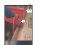
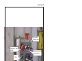
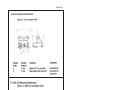
OCS Report
MMS 2001-045
Investigation of Fatality
Mississippi Canyon Block 167
OCS-G 08801
September 8, 2000
Gulf of Mexico
Off the Louisiana Coast
U.S. Department of the Interior
Minerals Management Service
Gulf of Mexico OCS Regional Office
OCS Report
MMS 2001-045
Investigation of Riser Fatality
Mississippi Canyon Block 167
OCS-G 08801
September 8, 2000
Gulf of Mexico
Off the Louisiana Coast
David Dykes
Tom Machado
U.S. Department of the Interior
Minerals Management Service
Gulf of Mexico OCS Regional Office
New Orleans
May 2001
Contents
Investigation and Report
Authority, 1
Procedures, 1
Introduction
Background, 4
Brief Description of Accident, 4
Findings
Weather Conditions, 5
Rig Activity at the Time of the Accident, 5
The Accident, 6
Description of the Cart Assembly, 6
Cart Joystick Panel, 9
Post-Accident Test of Cart Brakes, 9
Post-Accident Disassembly and Inspection by VMW Industries, 10
VMW Maintenance Procedures, 13
Marine Cart Inspection and Maintenance Procedures and Records, 15
Conclusions
Causes, 18
Contributing Causes, 18
Recommendations
Safety Alert, 20
Appendix
Attachment 1, Location of Lease OCS-G 08801, Mississippi Canyon Block 167
Attachment 2, Weather and Sea Effects on Marine 700
Attachment 3, Picture of the Cart Assembly Point of Contact
Attachment 4, Picture of the Iron Roughneck Point of Contact
Attachment 5, Diagram of the Accident Scene on 9-8-00 Marine 700
Attachment 6, Diagram of the Casing Bed and Cart Arrangement
Attachment 7, Example of Pin Type Positive Locking System
Attachment 8, Picture of the Cart Joystick Panel
Attachment 9, Cart Lubrication Charts.
ii
The Investigation and Report
Authority
An accident that resulted in one fatality occurred on Marine Drilling
Companies Incorporated (Marine) mobile offshore drilling unit, Marine
700, located on ExxonMobil Production Company’s (ExxonMobil)
Mississippi Canyon Block 167, Lease OCS-G 08801 in the Gulf of
Mexico, offshore the State of Louisiana, on September 8, 2000, at
approximately 0425 hours. Pursuant to Section 208, Subsection 22 (d),
(e), and (f), of the Outer Continental Shelf (OCS) Lands Act, as
amended in 1978, and the Department of the Interior Regulations
30 CFR 250, the Minerals Management Service (MMS) is required to
investigate and prepare a public report of this accident. By
memorandum dated September 14, 2000, the following personnel were
named to the investigative panel:
Procedures
David Dykes
New Orleans, Louisiana (Chairman)
Tom Machado
New Orleans, Louisiana
On September 9, 2000, an inspector from the MMS New Orleans
District visited the rig to assess the situation and began gathering
information, thereby initiating MMS’s investigation of the incident.
The visit started with a meeting to discuss the incident. The following
individuals attended the meeting.
Lead Inspector, New Orleans District
Marine Operations Manager
1
Marine Offshore Installation Manager
ExxonMobil Representatives (four present)
Marine Vice-President, Operations
Marine QA/HSE Director
Marine QA/QC Engineer
On September 22, 2000, ExxonMobil submitted their report of
investigation findings to the panel; the report included statements taken
by ExxonMobil and Marine from the following individuals the day of
the incident:
Driller
Assistant Driller
Toolpusher
Shaker hand
Floorhand
Roughneck
Halliburton hand
The panel received various documents from ExxonMobil, Marine, and
Victoria Machine Works (VMW) during the course of the
investigation. Technical information was gathered from Marine and
VMW records and from numerous telephone interviews with both
Marine and VMW personnel.
2
On March 20, 2001, the panel received Marine’s final incident report.
On March 29, 2001, the panel received ExxonMobil’s final incident
report.
The panel members met at various times throughout the investigation
and, after having considered all of the information available, produced
this report.
3
Introduction
Background
Lease OCS-G 08801 covers approximately 5,760 acres and is located in
Mississippi Canyon Block 167, Gulf of Mexico, off the Louisiana coast.
For lease location, see Attachment 1. The lease is jointly owned by
ExxonMobil Corporation and BP, Incorporated. The lease was issued
effective January 01, 2001, to ExxonMobil Corporation and BP
Exploration & Production, Incorporated. ExxonMobil became the
designated operator of the lease on September 19, 1994.
Brief Description
of Accident
During routine drilling operations on the MODU Marine 700, the riser
cart/carriage assembly moved forward, pinning a drilling floorhand
between the riser cart/carriage assembly and the iron roughneck on the
drillfloor. The floorhand received fatal injuries as a result of this
accident.
4
Findings
Weather
Conditions
At the time of the incident, the air temperature was 82 degrees
Fahrenheit and the barometric pressure was 30.19 inches. The wind
direction and speed were south-southwest (approximately 200o) at
approximately 10-15 knots. The seas were running out of the southsouthwest (approximately 200o heading) with a wave height of 4-6 feet.
The wave period at the time of the incident was six seconds. Wave
height is the measurement from mean sea level (MSL) to either the crest
(top) of the wave or trough (bottom) of the wave. Under these weather
conditions, the rig was experiencing a pitch of 0.1 degrees and a roll of
0.5 degrees. Pitch is the pivotal movement up and down of the rig along
the centerline axis from the bow to the stern. (When the bow goes up,
the stern goes down.) Roll is the pivotal movement up and down of the
rig along the centerline axis from port to starboard sides. When the port
side is up, the starboard side is down. The rig also had a heave of
approximately 1inch. Heave is the vertical movement up or down of the
rig along the surface of the water. Rig personnel stated during the initial
MMS visit that the rig also had a list of 0.25 – 0.5 degrees to the bow.
List is the relative leaning position of the rig with respect to the sea
surface. For weather and sea effects on Marine 700, see Attachment 2.
Rig Activity at the
Time of the
Accident
The rig was conducting drilling operations and at the time of the
accident; the rig crew was in the process of connecting drill pipe.
5
The Accident
At 0425 hours on September 08, 2000, the drill crew was in the process
of connecting the last string of drill pipe with the aid of an iron
roughneck. There were two floorhands operating the iron roughneck.
Floorhand #1 was watching the torque gauge on the iron roughneck
when the toolpusher and floorhand #2 noticed the casing cart rolling
towards floorhand #1. The cart hit him, pinning floorhand #1 between
the cart and the iron roughneck. For pictures of the points of contact,
see Attachments 3 & 4. The cart rolled back a few feet and floorhand #1
fell to the floor. The toolpusher went to the cart control panel and
attempted to move the cart away from floorhand #1. The cart would not
move, so the toolpusher told the driller to turn on the cart hydraulics and
then the toolpusher moved the cart away from floorhand #1. The medic
arrived on the drill floor at 0430 hours and started tending to floorhand
#1. At 0445 hours, floorhand #1 was taken to the rig hospital, where he
died at 0500 hours. For a diagram of the accident scene, see
Attachment 5.
Description of
the Cart
Assembly
At the time of the incident, the equipment was arranged to handle casing
with the casing bed. The position of the riser cart assembly faces aft to
bow directly behind the drill floor. For diagram of the casing bed and
cart arrangement, see Attachment 6. Victoria Machine Works (VMW)
manufactures the cart assembly in Corpus Christi, Texas; the following
6
equipment descriptions are based on its Operation and Service Manual
for the Riser Skate Cart Assembly (model number – 03-530-616).
Aft Cart
The purpose of the aft cart is to drive and support the aft end of
the casing bed to and from the gantry crane area. The aft cart is
powered by a hydraulic drive with a rack and pinion. The drive
has the ability to free wheel. There is also a spring-set hydraulic
release disc brake provided on the aft cart. This is a parking
brake only and can be set by pushing a button on the cart joystick
panel. Note: The brake on the aft cart consists of two sets of
caliper pads. One set is located on the front side of the rotor disk
and the other set is located on the aft side of the rotor disk.
Bumping the joystick in either direction disengages the brake.
The free wheel light will be illuminated when the brake is
disengaged. In the operation and service manual on page nine,
VMW states, “In case of emergency, press the emergency stop
button. This button will cut electrical power to the system. The
Aft Cart brake is hydraulic release and spring set. Losing
electrical power will cause the Aft cart brake to set.” During a
followup interview with VMW personnel, one individual stated
that with electrical power cut off to the cart, the aft cart brake
would set eventually as hydraulic pressure bleeds off in the
7
system. This may take some time, anywhere from two minutes
to several hours.
The aft cart is not equipped with any type of positive locking
device such as a pin (dog) to prevent unwanted movement. For
an example of a pin-type positive locking system, see
Attachment 7.
Utility Cart
The purpose of the utility cart is to transport miscellaneous cargo
from the riser loading area to the drill floor. There is no power
to the utility cart. The cart can be moved with air tuggers. The
cart is equipped to handle a safe working load of 67,000 pounds.
The utility cart is used in conjunction with the aft cart to support
the casing bed. The utility cart is not equipped with a parking
brake or any type of positive locking device to prevent unwanted
movement.
Casing Bed
The casing bed is designed to be installed between the Aft Cart
and the Utility Cart. The purpose of the casing bed is to
transport casing to and from the drill floor by utilizing the drive
ability of the Aft Cart. The casing bed is designed to support
8
five 30-foot long joints of 18-inch diameter schedule 160 pipe,
which equals 46,275 pounds equally distributed over any 30-foot
length of the casing bed.
According to Marine’s final report, the cart was last used on
September 07, 2000. At 1730 hours the cart’s parking brake was
engaged and the hydraulic power system was deactivated. The
approximate elapsed time until the incident was 11 hours.
Cart Joystick
Panel
The joystick panel for the aft cart is located on the drill floor inside the
drill floor wall. The joystick panel consists of one joystick, three
pushbuttons, and one signal light. The joystick controls the motion of
the aft cart. The top left button is the emergency stop button. The set
brake button, located in the center of the joystick panel, sets the brake on
the aft cart. The button is lighted to indicate the brake is set. The green
signal light on the right side of the joystick panel is lighted when the aft
cart is freewheeling. For picture of cart joystick panel, see
Attachment 8.
Post-Accident
Test of Cart
Brakes
ExxonMobil and Marine tested the cart the night of September 08, 2000.
They hooked up a tugger, started to pull very lightly, and the cart started
to move. They detected that the brakes on the cart were not working.
9
Post-Accident
Disassembly and
Inspection by
VMW Industries
Inspection of the failed brake system began at approximately 1900 hours
on September 09, 2000. VMW representatives conducted the inspection.
The following is a summary of the findings from VMW’s report:
Model number for both units:
03-530-616
Serial numbers:
98c-236-& 98c-209
1. Pressure tests indicated that 1,600 psi hydraulic pressure was
available at the brakes.
2. There was approximately 1/16” clearance between the aft brake
adjusting screw and the motor housing at the aft brakes, and zero
clearance between the forward brake adjusting screw and the motor
housing.
3. A .002 feeler gauge could not be fitted under either caliper pad and
the rotor of aft caliper brake when the brake was hydraulically
released.
4. Inspection of the forward brake caliper found the fixed caliper pad
destroyed and all four pad-retaining screws broken.
5. Inspection of the aft brake caliper found the fixed pad to be intact
with exception of elongated mounting holes and broken pad
mounting screws.
6. There was no obvious reason for the difference in the condition and
wear of the two pads of the forward brake as compared with the aft
brake.
7. The pivot pins for both brakes appeared to be well lubricated and
10
free moving.
8. The bearings for the drive shaft appeared to be well lubricated.
9. The mounting bolts for the brakes were corroded and difficult to
remove.
10. The adjustment bolts for both calipers were corroded and very tight.
11. Inspection of the brake rotor found no major scoring of the rotor
braking surface.
12. Inspection of the brake control valve found the solenoid retainer nut
missing but found the solenoid to be operating properly.
13. Visual inspection of the mounting plates indicated that there may be
some out-of-plane misalignment.
After removal from the drive system, the brake parts were photographed
and taken to the mechanic shop for further inspection.
Disassembly and visual inspection of the brake calipers revealed the
following:
1. Corrosion was apparent inside the aft spring compartments.
2. The internal spring parts appeared intact.
3. The spring stacking sequence was consistent with the manufacturer’s
documentation for both brakes.
4. The forward springs were found coated with a residue.
5. The aft springs were found lubricated.
11
6.
The hydraulic piston components appeared to be intact.
7. The forward bearings pad piston was slightly tarnished but free to
move.
8. The aft bearing pad piston was clean and free to move.
9. Both caliper housings were found to be wider at the mouth than at
the root. This was noted to be approximately 3/16” for the aft
housing and 1/4” for the forward brake housing.
After disassembly, all components were placed in marked individual
bags, the individual bags were placed in a box, and the box was taken to
the rig office and remains in the custody of the Marine Drilling QA/HSE
Director.
The following were concluded by the VMW and Marine inspection
team:
1. A pull test was conducted prior to the inspection and the brake
system was determined to be ineffective.
2. The forward brake assembly was found to be in a failed state.
3. The reason the aft brake assembly was not effective was not
determined at the time of the inspection and disassembly.
During a followup interview with VMW personnel, one individual
stated that the brake rotor and pads were contaminated with grease. The
12
inspection and disassembly report does not explicitly identify
contamination on the rotor and pads. However, the report does state that
certain factors ought to be investigated as reasons for the brake failure
and as possible design improvement: Those factors are as follows:
Possible caliper misalignment issues
Possible distortion of the caliper housing
Contamination of the caliper pads
The effectiveness of the spring assembly
The pad material.
VMW personnel also stated that, under ideal conditions, with everything
functioning properly and with no contamination of the braking surfaces,
the brakes (front and aft set of calipers) would hold a maximum load of
60,000 pounds at an incline angle of approximately 4-5 degrees. With
only one set of brakes (front or aft set of calipers) functioning properly,
the brakes could only hold to approximately a 2-degree maximum angle.
Add contamination to the braking surface, and the brake holding
capacity is significantly reduced.
VMW
Maintenance
Procedures
Maintenance procedures of the cart cover five main areas and are listed
below:
Electrical Maintenance
•
Monthly – Check inter-unit cabling for possible physical
damage. Correct.
13
•
Bi-Annually – Install new moisture absorption material in all
electrical enclosures. Ensure cabinets are sealed tightly when
closed.
Pneumatic Maintenance
•
Monthly – Check hoses for fatigue, cracks, and excessive
wear. Replace if needed.
Hydraulic Maintenance
•
Monthly – Check hoses for leaks, fatigue, cracks, and
excessive wear. Replace if needed.
Mechanical Maintenance – General
•
Monthly – Visually inspect the structure for weld integrity,
loose connecting hardware, and general condition. Bolted
connections should be checked for proper torque by using
torque values. Welds should be inspected for cracks. Should
a weld be suspect, verify using the dye-penetrate method.
Treat corrosion and paint effected areas.
Aft Cart and Utility Cart Mechanical Maintenance
•
Lubrication as per Cart Lubrication Charts Figures 5.2 and
5.3. For cart lubrication charts, see Attachment 9.
The VMW Operation and Service manual does not identify brake
inspections as part of any routine maintenance.
14
On pages 7 and 8 of the Operation and Service manual, the operation
procedures make reference to “calm sea operations.” The procedures
state in part, “When setting the Aft Cart brake, the green freewheel light
should turn off and the red brake light should turn on. (Also, during
calm sea operations, the brake may not be required. However, rough sea
operations require the parking brake to be set.)” VMW personnel
defined calm sea conditions, during the followup interview, as near zero
wave height.
According to Marine personnel on the rig, calm sea conditions are
determined by the pitch and roll of the drilling rig and not necessarily by
wave height. Rough sea conditions exist when there is either a pitch or
roll of the rig of at least 0.5 degrees. Calm seas are therefore determined
to be anything less than a 0.5 degree pitch or roll of the rig.
Marine Cart
Inspection and
Maintenance
Procedures and
Records
Marine’s inspection and maintenance procedures call for both a weekly
and monthly inspection of the aft powered riser cart. The procedures for
the weekly routine inspection are as follows:
•
Check hydraulic motor and valve and hose connections for
leaks.
•
Check power track for loose, missing, or damaged
components.
•
Check saddle and pivot bearings for any damage and
15
operation.
•
Clean any debris from rack, and check for missing or
damaged teeth. Remove any rust or corrosion and coat with
“taskmaster” or equivalent corrosion preventive medium.
•
Check all manual controls for freeness of operation.
Records indicate that weekly inspections occurred on
July 13, 2000
July 30, 2000
August 11, 2000
August 27, 2000
The procedures for the monthly routine inspection are as follows:
•
Perform all weekly scheduled checks.
•
Check brake components for wear or other operation defects.
•
Visually inspect the entire cart assembly for all mounting
hardware and any indication of damaged paint. Repair as
necessary.
•
Visually check all power track components to include covers
and hinges.
Records indicate that monthly inspections occurred on:
June 26, 2000
July 30, 2000
Several attempts were made by the panel to obtain a copy of the
August 2000 inspection from Marine. However, at the time of
16
writing of this report, the panel has not received any proof of an
August inspection.
The records indicate that the steps identified above were taken; however,
the records do not show the exact process undertaken, deficiencies
found, or any corrective measures taken. The records show simply a
check (!) by each step, indicating that it was performed.
17
Conclusions
Causes
The unintentional movement of the riser cart assembly was caused by
the movement and list of the rig and the lack of brake-holding capacity
of the aft powered cart.
Contributing
Causes
The movement of the rig was caused by the sea conditions at the time
of the accident and the relative position of the rig. The sea conditions
created enough pitch and heave, coupled with the list of the rig, to
cause the cart to move from its stationary position toward the rig floor.
This movement continued until the cart assembly fatally struck the
Marine employee and pinned him against the iron roughneck.
Therefore, the sea conditions and their effect on the rig at the time of
the accident are considered to be contributing causes of the accident.
The loss of brake-holding capacity was caused by contamination of the
brake rotor and pads with grease and also by the state of disrepair of the
forward caliper pads. Therefore, the contamination of the brake rotor
and pads and the state of disrepair of the forward caliper pads are
considered to be contributing causes of the accident.
Marine could not provide this panel with the monthly aft powered riser
cart inspection form for the month of August 2000. The monthly
18
inspection identifies checking the brake components for wear and other
operational defects. It is possible that this inspection would have
detected the contamination and the state of disrepair of the braking
system. At the time of this report, the cause of the failed state for the
forward caliper pads has not been determined. It is the conclusion of
this panel that Marine failed to conduct a monthly aft powered riser cart
inspection during the month of August. The failure of Marine to
conduct the monthly aft powered riser cart inspection during the month
of August is considered to be a possible contributing cause to this
event.
The failure of VMW to provide a secondary lockout device or a
secondary procedure (as a backup to the brakes) to prevent unwanted
movement of the casing cart assembly is considered to be a
contributing factor. If a positive locking device such as a pin had been
provided, it might have been used to prevent unwanted movement of
the cart, thereby preventing the accident. However, the availability of a
positive locking device does not guarantee its use.
19
Recommendations
Safety Alert
The MMS should issue a Safety Alert recommending that drilling
contractors who use this type of riser and casing-handling equipment
review the operations and maintenance for the purpose of identifying
weaknesses. Their review should include but not be limited to the
following items:
•
Clearly defined procedures for the use of and storage of the riser
and casing cart assemblies.
•
Detailed inspection and maintenance procedures for all critical
operating components.
•
Detailed documentation of inspection findings and corrective
measures taken.
•
The use of a pin-type, positive-locking device or other method to
prevent unwanted movement when the cart assembly is not in use.
20
LOUISIANA
ALABAMA
MISSISSIPPI
TEXAS
MOBILE
BATON ROUGE
BILOXI
PENSACOLA
LAKE CHARLES
PANAMA CITY
LAFAYETTE
MOBILE
NEW ORLEANS
HOUSTON
VIOSCA
HOUMA
CORPUS CHRISTI
MUSTANG
IS.
NORTH
PADRE IS.
SOUTH
PADRE IS.
G.I.
DESTIN DOME
APALACHICOLA
KNOLL
W.D.
S.P.
SO. TIMBALIER
SHIP SHOAL
EUGENE IS.
VERMILION
SOUTH MARSH IS.
EAST CAMERON
WEST CAMERON
HIGH ISLAND
GALVESTON
BRAZOS
MAT.
IS.
MAIN
B.S.
PASS
GRAND ISLE
GALVESTON
PENSACOLA
GA
INE
SV
ILL
E
SO.
PASS
MISSISSIPPI CANYON
DESOTO CANYON
FLORIDA
MIDDLE GROUND
TAMPA
EAST BREAKS
GARDEN BANKS
ALAMINOS CANYON
KEATHLEY CANYON
GREEN CANYON
ATWATER
LLOYD
THE ELBOW
LUND
HENDERSON
VERNON
ST.
PETERSBURG
CORPUS
CHRISTI
PORT
ISABEL
NG 15-8
Western
WALKER RIDGE
NG 15-9
NG 16-7
CHARLOTTE
HARBOR
MIAMI
NG 16-8
HOWELL HOOK
PULLEY RIDGE
Central
MIAMI
RANKIN
Eastern
DRY
TORTUGAS
STATUTE MILES 0
KEY WEST
50
100
U.S. Department of the Interior
Minerals Management Service
Gulf of Mexico OCS Region
Location of Lease OCS-G 08801,Mississippi Canyon Block 167
KILOMETERS 0
100
200
Attachment 1
Mississippi Canyon
Block 167
OCS-G08801
MM
FLORIDA
TARPON
SPRINGS
N
Bow
o
Attachment 2
Roll 0.5
o
Heading
18.4
Port
Cart Assembly
Starboard
o
List
0.25-0.5
o
Pitch
0.1
Wind 10-15 mph
Seas 4’-6’
Stern
Seas - MSL to Crest of Wave
Weather and Sea Effects on Marine 700
X
Point of Contact with
floorhand #1
Attachment 3
Picture of Cart Assembly Point of Contact
Attachment 4
Floorhand #1was
reading this gauge
X
Point of contact
with floorhand #1
Floorhand #1 was
standing here.
X
Picture of Iron Roughneck Point of Contact
AFT Cart
Cart Joystick Panel
Stopper
Drill Floor Wind Wall
VMW Industries
Utility/Casing
Cart 30,000 lbs.
Hydo Control
Power to
Cart
…
Draw
Works
Drilling
Shack
Iron
Roughneck
One Joint 3”
Gauge
Drill Pipe 30’
Floorhand #1
X
18.4’
54.4’ Cart Length
X
38.8’ Travel Distance
Floorhand #2
Bow
Attachment 5
Diagram of Accident Scene on 9-8-00 Marine 700
Casing Bed
Aft
Powered
Cart
Utility Cart
Attachment 6
Diagram of Casing Bed and Cart Arrangement
Attachment 7
Rear Cart
Pin
Pin
Rear Cart Stop
Example of Pin Type Positive Locking System
Attachment 8
Free-wheel
indicator light
Emergency Stop
Button
Aft Powered Cart
Brake Button
Horn
Cart Joystick
Picture of Cart Joystick Panel
Attachment 9
Cart Lubrication Charts