1
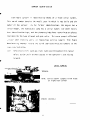
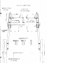
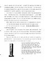
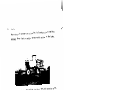
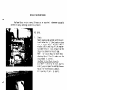
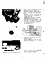
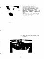
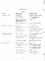
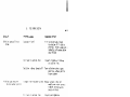
OPERATOR'S MANUAL
FOR
HAGlE MODEL 280 HI-TRACTOR
HAGIE MANUFACTURING COMPANY
BOX 273 CLARION, IOWA 50525
COVERS MACHINE SERIAL NUMBERS:
(515)532-2861
018929001 Thru 018929200
A WORD FROM HAGIE MANUFACTURING COMPANY
Congratulations on your selection o f a Hagie Model 280 sprayer,
We
recommend t h a t you study t h i s Operator's Manual and become acquainted with
t h e a d j u s t m e n t s and operating procedures b e f o r e attempting to operate your
new sprayer.
As w i t h any piece of equipment, c e r t a i n operating procedures,
s e r v i c e , and maintenance are required to keep it in top running condition.
We have attempted h e r e i n to cover
v a r y i n g conditions.
However,
all o f the adjustments required to fit
there must be times when special care must be
considered.
Hagie
Manufacturing company reserves t h e right to make changes i n t h e
design and materi a1 o f any subsequent sprayer w i t h o u t obl igation to e x i s t i n g
units.
We thank you f o r choosing a H a g i e sprayer and assure you o f our
continued i n t e r e s t in i t s satisfactory o p e r a t i o n for you.
assistance t o you, p l e a s e call on u s .
We are p r o u d t,o have you
as a customer.
I f we might be o f
1
+
2
5Y
pl
(n
7
o m 3
n a-.
-0
%
0-n 2
A.
a - m
n] 0-3
rtc
A *-0
SPRAYER I D E N T I F I C A T I O N
Each Hagie s p r a y e r i s i d e n t i f i e d by means o f a frame s e r i a l number.
T h i s s e r i a1 number d e n o t e s the model, year in which i t was built and t h e
number o f t h e s p r a y e r .
As f o r further i d e n t i f i c a t i o n , t h e engine has a
s e r i a l number, t h e h y d r o s t a t i c pump has a s e r i a l number, t h e wheel motors
have identification t a g s , and the planetary hubs have identification plates
t h a t d e s c r i b e t h e t y p e o f mount and gear r a t i o .
service
when
To insure prompt, e f f i c i e n t
ordering parts or requesting s e r v i c e repairs from Hagie
M a n u f a c t u r i n g Company, record t h e s e r i a l and i d e n t i f i c a t i o n numbers in t h e
space
Note:
provided be1 ow.
Reference t o l e f t h a n d and right hand used throughout this manual
r e f e r s t o t h e p o s i t i o n when s e a t e d i n t h e o p e r a t o r ' s s e a t f a c i n g
forward.
S E R I A L NUMBERS
SPRAYER
NOTE: Serial number stamped i n t h e f r a m e
on r i g h t r e a r corner
ENGINE ( D I E S E L )
ITEM
u
4
SPECIFICATIONS
Cab
-
Air conditioning ..................,..,.......
Standard
F i l t e r ...........,.....................,...
Paper & Charcoal
Glass ........................................ S a f e t y tinted
4
Windshield wiper ............................
Standard
................................Stereo c a s s e t t e
fl ashers. .....................
...Standard
Radio (AM/FM)
L i g h t s and
Mirrors (2) ..........,.......................
w/clock
Rear view
Operator's Station and Controls
Seat . . . . . . . . . . . . . . . . . . . . . . . . . . . . . . . . . . . . . .
Bucket, adjustable
Speedometer . . . . . . . . . . . . . . . . . . . . . . . . . . . . . . . . S l i d s t a t e electronic
1
Indicator lights . . . . . . . . . . . . . . . . . . . . . . . . . . . . . Oil pressure; alternator
Gauges. . . . . . . . . . . . . . . . . . . . . . . . . . . . . . . . . . . . . . Temperature
w
Ladders (2 rear) . . . . . . . . . . . . . . . . . . . . . . . . . ,..Mounted
eng ine cool a n t , fuel , hour
w/service platforms
Capacities
Fuel tanks ( 2 ) . . . . . . . . . . . . . . . . . . . . . . . . . . . . . . . 40 gallons each
Cool i n g system. ............................. .Seven (7) gal l ons
Hydraulic reservoir .......................... 20 gallons
Tires ( f r o n t and r e a r ) . .................... . 1 8 - 2 2
PSI maximum
;
L
m E
ClrP
m cr.
rn
VI
2"
--
er
~n co
w 2
A. A. k
-,
P;
3
3 .
ID
<
-
+<
A-mo *
2.
l-k
'
I
m
r+
Ll
m
'j
0
-+!
ID
0-
LO
;
k
m
n
3
n
n
m
2
gr
< *
a-r m m
- - m *-'I
n
d 2.
n-3
0 0
A. 0
0 --cD
3
w
3-
m n
--0
(n
rt A. '
I 0 cD
7
*PJ
A
.
7.
Turn t h e i g n i t i o n key s w i t c h t o t h e s t a r t p o s i t i o n t o e n g a g e t h e s t a r t e r .
I f t h e engine f a i l s t o s t a r t a f t e r 15 seconds, t u r n key t o off, w a i t one
minute and r e p e a t t h e procedure. If t h e engine does not s t a r t a f t e r
t h r e e attempts, check f u e l supply system. Absence o f b l u e o r w h i t e exexhaust smoke d u r i n g c r a n k i n g i n d i c a t e s no f u e l i s b e i n g d e l i v e r e d .
When engine s t a r t s , immediately reduce t h r o t t l e 1 ever s e t t i n g t o 1/3.
8.
Inspect i n d i c a t o r l i g h t s andgauges f o r c o r r e c t o p e r a t i o n .
If anylights
or gauges do n o t operate, shut o f f engine and determine cause.
9.
Always a l l o w a t l e a s t a f i v e - m i n u t e warm-up p e r i o d b e f o r e o p e r a t i n g t h e
engine a t h i g h RPM. T h i s means t h e engine must r e a c h o p e r a t i n g
temperature and o i l pressure must s t a b i l i z e i n t h e normal o p e r a t i n g range
b e f o r e i t i s r u n f a s t e r than an i d l e (1000 RPM o r l e s s ) .
NOTE: Cold o i l may n o t f l o w i n q u a n t i t i e s adequate t o p r e v e n t pump
c a v i t a t i o n , t h u s causing damage t o t h e pump which w i l l l e a d t o pump
failure.
COLD WEATHER
STARTING ( D I E S E L 1
Using s t a r t i n g f l u i d without m e t e r i n g equipment:
WARNING: Never use s t a r t i n g f l u i d near an open flame, o r w i t h a
p r e - h e a t e r o r f l a m e thrower equipment. T h i s combination can cause an
explosion.
WARNING: Do n o t breathe s t a r t i n g f l u i d fumes.
can be harmful to y o u r h e a l t h .
S t a r t i n g f l u i d fumes
CAUTION: Do n o t use excessive amounts o f s t a r t i n g f l u i d when
s t a r t i n g an engine. The use o f t o o much s t a r t i n g f l u i d w i l l cause
engine damage.
Spray s t a r t i n g f l u i d i n t o the a i r c l e a n e r i n t a k e w h i l e another
person cranks t h e engine.
When s t a r t i n g t h e sprayer u s i n g jumper cables, f o l l o w t h e s e steps:
Caution:
When u s i n g jumper cables t o s t a r t t h e engine, make sure
t o connect t h e c a b l e s i n p a r a l l e l : p o s i t i v e (t) t o p o s i t i v e (t)
and n e g a t i v e ( - ) t o n e g a t i v e ( - ) . When u s i n g an e x t e r n a l e l e c t r i c a l
source t o s t a r t t h e engine, t u r n t h e d i s c o n n e c t s w i t c h t o t h e " o f f "
p o s i t i o n . Remove t h e key b e f o r e a t t a c h i n g t h e jumper c a b l e s t o
prevent u n i n t e n t i o n a l s t a r t e r engagement.
HYDROSTATIC D R I V E
The Hagie 280 Sprayer i s d e r i v e d from a Cummins diesel e n g i n e .
The
h y d r o s t a t i c power system consi s t s o f a Sauer/Sundstrand heavy d u t y v a r i a b l e
displacement pump and f i x e d displacement motors.
A manual c o n t r o l l e v e r
connected t o t h e pump swash plate c o n t r o l s the amount and d i r e c t i o n o f o i l
flow t o t h e m o t o r s , determining t h e speed and d i r e c t i o n o f t h e machine.
Open t h e t h r o t t l e s l o w l y t o t h e maximum recommended e n g i n e speed s e t t i n g .
CAUTION: Never o p e r a t e t h e s p r a y e r a t a n y t h i n g l e s s t h a n f u l l recommended
throttle.
To move f o r w a r d , s l o w l y push t h e h y d r o s t a t i c c o n t r o l l e v e r forward. The
f a r t h e r t h e c o n t r o l l e v e r i s moved, t h e f a s t e r t h e sprayer w i l l t r a v e l .
To s t o p , s l o w l y p u l l t h e h y d r o s t a t i c c o n t r o l l e v e r t o t h e N ( n e u t r a l )
position.
To move backwards, slowly p u l l t h e h y d r o s t a t i c c o n t r o l l e v e r backwards.
The f a r t h e r t h e c o n t r o l l e v e r i s moved, t h e faster the sprayer w i l l
travel .
To s t o p , slowly push t h e h y d r o s t a t i c c o n t r o l l e v e r t o the N ( n e u t r a l )
position.
Before t u r n i n g o f f t h e e n g i n e , c l o s e t h e t h r o t t l e t o reduce engine speed
and a1 1 ow t h e e n g i n e t o i d l e a t l e a s t 3 m i n u t e s .
To s h u t o f f t h e Cummins e n g i n e , t u r n o f f t h e i g n i t i o n s w i t c h .
S e t t h e b r a k e s when p a r k i n g t h e s p r a y e r on a h i l l o r s l o p e .
To engage y o u r h y d r o s t a t i c system in four-wheel d r i v e , p u l l up on t h e
c o n t r o l knob.
e
HYDRAULICS
U
The a u x i l i a r y h y d r a u l i c system i s an open t y p e d i r e c t l y connected t o t h e
heavy duty v a r i a b l e d i s p l a c e m e n t pump (Item 1; F i g u r e 2 ) .
T h i s system c o n s i s t s
o f a gear- t y p e pump t h a t suppl i es t h e r e q u i r e d hydraul i cs t o operate the f u l l
time power s t e e r i ng u n i t
.
The boom c o n t r o l s t h e s o l u t ion pump and mechani cal
agitation.
Fig.
1.
Boom c o n t r o l levers o p e r a t e t h e 1 i f t ,
l e v e l i n g , and f o l d cyl inders. Item I ;
F i g u r e 1.
CAUTION: Be sure everyone i s a s a f e
d i s t a n c e away from t h e sprayer b e f o r e
o p e r a t i n g 1e v e r s .
2.
The s o l u t i o n v a r i a b l e f l o w c o n t r o l l e v e r
3.
4
u)l
Fig.
2
1
o p e r a t e s t h e s o l u t i on pump hydraul i c
motor f o r s p r a y p r e s s u r e . The more
s o l u t i on p r e s s u r e d e s i r e d , t h e f u r t h e r
t h e l e v e r needs t o be moved f o r w a r d .
Item 2 ; F i g u r e 1 .
The a g i t a t i o n v a r i a b l e flow c o n t r o l l e v e r
o p e r a t e s t h e h y d r a u l i c motor f o r t h e
r e q u i r e d speed. The more speed r e q u i r e d , t h e f a r t h e r t h e l e v e r needs t o be
moved forward. Item 3 ; F i g u r e 1
A I R CONDITIONER
The cab is equipped with an a i r c o n d i t i o n e r .
The c o n t r o l s f o r t h e a i r
conditioner are l o c a t e d overhead and toward t h e f r o n t o f t h e cab.
Fig.
1
1.
The fan speed control s w i t c h regulates t h e amount o f a i r f l o w o u t o f
t h e blower system. When t h i s s w i t c h i s o f f , t h e air c o n d i t i o n e r will
not run.
2.
The temperature switch is a thermostat switch t h a t c o n t r o l s t h e temperature w i t h i n the c a b . Turning t h e s w i t c h to t h e r i g h t will increase
the coolness o f t h e a i r to be circulated.
3.
Vent knob ( I t e m 1; Figure 1) - t h i s k n o b c a n be adjusted t o c o n t r o l the
amount o f o u t s i d e air needed for proper v e n t i l a t i o n .
4.
CAUTION: To p r e v e n t air c o n d i t i o n e r compressor damage and condenser
freezing, inside and/or outside, air i n t a k e vents must be open.
5.
Filter cleaning: remove t h e two upper thumb screws, drop the door
down and remove t h e paper filter. Clean by u s i n g a i r pressure o r replace as needed.
For charcoal fi 1 ters, remove and rep1 a c e when chemical odor comes i n t o
the c a b through t h e filter.
i
SOLUTION TANKS
The Model 280 can come equipped w i t h e i t h e r two 4 0 0 - g a l l o n p o l y e t h y l e n e
or s t a i n l e s s steel tanks w i t h mechanical a g i t a t i o n . The s t a i n l e s s steel tanks
are held in p l a c e w i t h mounting b o l t s and s p r i n g s .
Tighten only enough t o
s t a r t t o compress t h e springs.
S W C LJ., 51 I TCR
3C nu; h~
ns ;;
I!L
L33.i !;
I!l!hl
( L I T U310R I I ! :
Y / I L & . c - 1 i*#$F- AJC,l>
' I ~'Euoh-I;?.H" 4DPlI
>:IIY. I - 5 0 - ' / L U h F - 13:
<,*A; 1 BEL .I<*: l 5 ' ' 8, :b: !H:
5.1A.1 :.KC. ,l'.Y..
J!?
'I->[, I
:(.hC
nix
'/<Lh[
:!*I;
c
A#>
V"
!;I'
l4zrllFP
1 < 1 - S - A r ' :a>
9
2,A"I I & [ I , C
a
:.I:
b:ll
UTi U - P 1 [ [ 1 ;i;m
3
<! 1 ' " l ? Ck, P ?!!
I
,
: It!,:
1
,EL'","
I 'run:
!: t
! , o - = I E3,
1
'.'?,V3-
'
'
4-1
, 4'
:':hc
c
s-crtl
*I!HiP
;,E
'
-
i x 87,'
,
< - " " , J
ClA,
*,;k
,I
-:,
h:
I*-
L.
:',"<,:>:
~iv - h u ! > ? K t :.j :b:
1 - 5 L O 5
Fig.
-
:A-
:
;
1
AGITATOR MOTORS
The a g i t a t o r motors f o r both t h e polyethylene and s t a i n l e s s steel t a n k s
are held i n place w i t h a motor mount yoke (see Item 3; Figure 1).
The yoke
t a p must extend through t h e motor mounting p l a t e (Item 4 ) t o a1 1ow t h e m o t o r
t o f l o a t with t h e a g i t a t o r s h a f t .
CAUTION:
Damage will occur t o t h e a g i t a t o r system i f t h e motor mounting yoke
i s n o t properly i n s t a l l e d i n t h e motor mounting p l a t e .
Fig.
7.
Observe s o l u t i o n p r e s s u r e gauge and
a d j u s t s o l u t i o n pump v a r i a b l e flow
control 1ever i f necessary.
8.
A d j u s t booms i f necessary.
9.
P1aceindividualsolutionvalveswitches
t o t h e " o n " p o s i t i o n . (Item I ; F i g u r e 2)
1
Turn on main s o l u t i o n v a l v e s w i t c h .
(Item 1 ; Figure 3 )
Slowly move t h e h y d r o s t a t i c c o n t r o l
lever forward t o o b t a i n the d e s i r e d
ground s p e e d .
A d j u s t spray p r e s s u r e t o the d e s i r e d
s e t t i n g by u s i n g s o l u t i o n pump v a r i a b l e
flow control lever.
Frequently observe the pressure gauge and
speedometer i n order t o apply t h e d e s i r e d
amount o f cherni cal deterrni ned when
cal ib r a t i ng t h e s p r a y e r .
Fig.
2
14.
When pressure gauge drops t o z e r o , o r
spray p a t t e r n q u i t s , shut o f f main
solution v a l v e s w i t c h , s o l u t i o n pump, and
a g i t a t i o n system u n t i l refill i n g s o l u t i o n
tanks.
WARNING: Operating the spray system with
no s o l u t i o n i n t h e tanks w i l l c a u s e
severe damage and v o i d a1 1 w a r r a n t i e s .
- -
I f equipped w i t h a Raven SCS 440 m o n i t o r ,
r e f e r t o Raven's I n s t a l l a t i o n and Service
manual t o c a l i b r a t e your m o n i t o r .
Fig.
3
CALIBRATION
f"
I t i s i m p o r t a n t t o apply chemical s as recommended by t h e manufacturers of
t h e chemical
products. In order to do so, one must calibrate the sprayer using
t h e steps o u t l i n e d below.
D e t e r m i n e t h e speed a t which t h e sprayer w i l l be d r i v e n w h i l e applying
chemicals. To select t h e b e s t speed, consider t h e lay o f the land, the condition
soil, the t y p e of c r o p s , t h e h e i g h t o f t h e crops, e t c .
o f the
C a l i b r a t e (measure t h e actual speed) t h e speedometer to t h e desired speed.
T e s t t h e speedometer by d r i v i n g along a pre-measured d i s t a n c e .
For example, i f
one wishes to spray a t a speed o f f i v e m i l e s p e r hour (MPH), one should drive one
12 m i n u t e s , and then n o t e t h e actual l o c a t i o n o f t h e speedometer needle
mile i n
i n relation to f i v e MPH on the d i a l .
Select t h e nozzle spacing (di stance between each nozzle on t h e spray boom)
b e s t s u i t e d f o r the intended spraying job.
NOTE: For help
i n d e t e r m i n i n g t h e n o z z l e spacing and h e i g h t o f boom,
refer to t h e spray product c a t a l o g that accompanies this manual .
There are several types and s i z e s of n o z z l e s .
and s i z e of n o z z l e s t h a t a r e
S e l e c t and instal 1 the type
best for the intended spraying j o b and f o r t h e speed
t h a t one i n t e n d s t o travel while spraying. The t y p e and
size
of
nozzles selected
will depend upon t h e speed the sprayer w i l l travel, t h e nozzle s p a c i n g , and the
number o f
gallons that one intends to apply per acre.
NOTE: When selecting t h e t y p e and s i z e o f nozzles, refer to t h e spray
product c a t a l o g .
EXAMPLE:
spacing,
o f 10
Assume t h a t one i n t e n d s t o
spray at f i v e MPH w i t h 30-inch nozzle
using flat s p r a y nozzles for broadcasting a h e r b i c i d e , at t h e rate
gallons per a c r e .
In order t o s e l e c t t h e
b e s t nozzles, use t h e Hagie
calibration tube. Select a c h a r t near t h e bottom o f t h e t u b e by using " t i p
(nozzle) spacing" and "miles p e r hour".
Using 30-inch spacing a t f i v e MPH, t h e
corresponding number (.251) on t h a t c h a r t i s t h e "flow r a t e " .
The f l o w r a t e i s
t h e amount o f l i q u i d t h a t i s a p p l i e d from one nozzle i n one minute, measured i n
thousandths o f a g a l l o n (based on a rate o f 10 g a l l o n s p e r acre).
Use a c h a r t i n a s p r a y p r o d u c t s c a t a l o g t h a t covers f l a t s p r a y i n g n o z z l e s
(tips).
Read down t h e column i n t h e catalog marked capacity 1 - nozzle (GPM)
u n t i l the number .25 i s found or the number c l o s e s t t o i t . Then read l e f t t o t h e
column marked t i p number; t h i s will g i v e you t h e nozzle ( t i p ) number having a
del i v e r y rate w i t h i n t h e d e s i red spraying p r e s s u r e .
NOTE:
Check w i t h the chemical manufacturer o n recommended s p r a y pressure.
T e s t and c a l i b r a t e (measure the a c t u a l flow r a t e ) t h e spray system.
F i l l t h e s o l u t i o n t a n k with clean w a t e r .
DO NOT ADD CHEMICALS UNTIL
CALIBRATION IS COMPLETED.
Apply t h e b r a k e s , s t a r t t h e engine o f t h e s p r a y e r , and remain p a r k e d . T u r n
on the main, r i g h t , c e n t e r , and l e f t s o l u t i o n s w i t c h e s , Move t h e s o l u t i o n pump's
v a r i a b l e flow c o n t r o l l e v e r u n t i l t h e p r e s s u r e gauge reads t h e d e s i r e d pressure
f o r t h e above exampl e .
Make s u r e t h a t there a r e no l e a k s and t h a t a l l n o z z l e s a r e s p r a y i n g a
desirable pattern.
Continue spraying i n t h e s t a t i o n a r y p o s i t i o n f o r a t l e a s t 10
minutes f o r proper warm-up of t h e s p r a y e r and i t s system
Use t h e c a l i b r a t i o n tube t o c a t c h one
n o z z l e ' s s p r a y f o r one m i n u t e . ( I f the
flow r a t e i s more than t h e tube w i l l
hold, c a t c h t h e spray in a l a r g e r cont a i n e r and then pour i t i n t o the t u b e . For
t h e example given above, a l a r g e r c o n t a i n e r
w i l l have t o be used. )
The numbered marks on t h e s i d e o f t h e c a l i b r a t i o n tube show t h e flow r a t e . The
measured flow r a t e should be the same a s the
flow r a t e shown on t h e c h a r t n e a r t h e bottom
of t h e c a l i b r a t i o n t u b e - .251.
1
A.
a
m
m
E
Ln
Y
3
2.
'P
V,
0 3
J CD
--+
-'.
ID
rt
0 C
w'5
D
c
m ax V,
e*
m
3 3
CIW
m 7r
a m
v r 3
e
A.
on
+ T
0
art
m
f
1 3
E rF
6
m m
Y f
vr
3-m
w w
J
+ID
-7
37
Pl m
5.
Checkoil level i n t o r q u e h u b s . P o s i t i o n
hubs w i t h check level plug i n t h e
h o r i z o n t a l position. Remove plug; i f
EP-90 o i l i s needed, remove top plug
and f i l l t o proper l e v e l ; reinstall
plugs.
Oil chanqe: I n i t i a l - after t h e f i r s t
50 hours of o p e r a t i o n , preferably i n
a loaded c o n d i t i o n .
Subsequently - 1000 hours or one year,
whichever comes f i r s t .
Front and rear torque hubs haye a
supplementary seal t h a t keeps d i r t and
o t h e r d e b r i s from main o i l seal. The
seal boot i s 1 ubri cated by grease which
i s i n j e c t e d through a zerk f i t t i n g
motor mounting bolt.
6.
Check front and rear lug n u t s ; torque
t o 8 5 - f o o t pounds.
CAUTION: Damage will occur t o r i m and
torque hub i f 1 ug nuts are n o t checked
often and kept t i g h t .
Loosen a i r cleaner clamp.
Remove and
check a i r cleaner element and rep1 ace
w i t h new element i f required.
Check hydraul i c oil level in
reservoir and add if necessary
( F i g u r e I).
Hydraul ic oil must con
form to one of t h e following types:
a n t i -wear hydraul i c oi 1, type F
automatic transmission f l u i d ,
agri cu1 tural hydraul i c transmi ss
fluid.
Replace the oil in t h e hydraulic reservoir every 500 hours o r at the begi n n i n g of each spraying season, whiche ver
comes f i r s t .
Fig.
1
10.
Remove and clean line strainer screen
(Figure 2 ) .
Perform these service and maintenance checks every f i f t y (50) hours o f use.
4R
Remove and i n s t a l 1 a new h y d r o s t a t i c pump
suction f i l t e r a t t h e end o f t h e f i r s t
50 hours o f use; subsequently, every 200
hours o r once a y e a r , whichever comes
f i r s t . See F i g u r e 1.
Fig.
1
CAUTION: Never install anything other
than a 10 Micron f i l t e r .
Inspect and c l e a n , i f necessary, a1 1
battery connections i f c o r r o s i o n i s
p r e s e n t and check tension o f b a t t e r y hold
down b r a c k e t . See Figure 2 .
Check leg mounting b o l t s ; be s u r e they
are t i g h t .
Check the s t e e r i n g t i e rod linkage;
be sure i t i s t i g h t . See Figure 3 .
Check p a r k i n g brake t e n s i o n and a d j u s t i f
necessary.
Fig.
2
Check t o m a i n t a i n an adequate neutral
s e t t i n g of t h e h y d r o s t a t i c pump.
MAINTENANCE GUIDELINES FOR YOUR DIESEL ENGINE
Every 100 hours of u s e , perform t h e s e
1.
service and maintenance checks.
Drain e n g i n e c r a n k c a s e oil and replace it w i t h recommended oil.
Use h i g h quality multi-grade lubricating oil i n Cummins
Choose the correct o i l for your o p e r a t i n g cl imate as
out1 i n e d i n Speci fications and Torque Val ues (Section 1 1 ) in
Engine O p e r a t i o n and Maintenance manual.
NOTE :
engines.
2.
I n s p e c t oi 1 (Figure 2) in hydraul i c reservoir for any foreign m a t e r i a1
(contamination j and rep1 ace w i t h approved oi 1 i f necessary ( s e e Page 3 8 ) .
Replace t h e oil i n t h e hydraul i c reservoir every 500 hours or at t h e
beginning o f each s p r a y season, whichever comes f i r s t .
STORAGE
A.
P r e p a r i n g t h e 280 Sprayer for s t o r a g e .
1.
Drain the c o o l a n t from t h e e n g i n e and radiator.
Probe the drain
h o l e s d u r i n g d r a i n i n g t o e n s u r e they are n o t clogged by s l u d g e ,
s c a l e , o r o t h e r deposits.
F i l l t h e c o o l i n g system t o t h e top with
a 50-50 w a t e r / a n t i - f r e e z e m i x t u r e .
Run engine to
operating
t e m p e r a t u r e and re-check 1eve1 .
NOTE:
I f a n t i - f r e e z e i s added, make sure t h e engine i s run t o
o p e r a t i n g t e m p e r a t u r e t o a s s u r e proper m i x i ng o f s o l u t i o n .
2.
Add a f u e l s t a b i l i z e r t o t h e f u e l and f i l l fuel tank.
3.
Run t h e e n g i n e u n t i l i t i s a t operating temperature, t h e n d r a i n
t h e engine o i l .
R e f i l l with new engine o i l a n d install a new
l u b r i c a t i n g o i l f i l t e r element.
4.
Run t h e
engine u n t i l
i t r e a c h e s normal
operating t e m p e r a t u r e .
Cycle a1 1 hydraul i c f u n c t i o n s i n c l u d i n g t h e steering.
5.
Release t e n s i o n o n a l l belts.
For more d e t a i l e d
information,
see t h e e n q i n e m a n u f a c t u r e r ' s
handbook.
6.
Use p l a s t i c bags and water r e s i s t a n t a d h e s i v e tape t o s e a l t h e a i r
i n t a k e opening, t h e e x h a u s t m a n i f o l d o r i f i c e , and t h e a i r v e n t on
the fuel tank.
7.
D i s c o n n e c t and remove b a t t e r y o r batteries.
charge t h e b a t t e r y .
Completely c l e a n and
Coat t h e terminals with petroleum j e l l y and
store battery i n cool, dry place.
8.
Thoroughly c l e a n t h e s p r a y e r .
Touch u p any p a i n t e d s u r f a c e s t h a t
are s c r a t c h e d or c h i p p e d .
9.
Rep1ace worn decal s .
Contact Hagie Manufacturing Company, Box
273, C l a r i o n , Iowa 50525, f o r replacement d e c a l s .
10.
Use a m u l t i - p u r p o s e grease t o c o a t
exposed hydraul i c cyl i n d e r
rods.
11.
To w i n t e r i z e t h e spray system, use a pre-mixed s o l u t i o n o f 50-50
permanent type anti-freeze and water.
the spray system u n t i l it comes out all
12.
Run t h i s m i x t u r e through
boom openings.
Use a p l a s t i c bag and water r e s i s t a n t adhesive tape t o seal t h e
engine o i l f i l l e r cap and t h e hydraulic o i l t a n k breather cap.
13.
I f t h e sprayer must be stored outside, cover i t with a waterproof
cover.
Removing the 280 S p r a y e r from storage.
1.
Check t h e condition and air p r e s s u r e o f a11 t h e t i r e s .
Check the
s e c t i o n on specifications far p r o p e r p r e s s u r e .
2.
Unseal a1 l o p e n i n g s t h a t were sealed i n the s t o r a g e procedures.
3.
Clean and i n s t a l l t h e b a t t e r y .
Be sure to attach t h e b a t t e r y
cab1 es t o proper t e r m i n a l s .
4.
Tighten a l l b e l t s .
5.
Check l e v e l s of engine o i l ,
Add, i f necessary.
R e p l a c e any worn b e l t s .
hydraulic o i l
and engine c o o l a n t .
Remember, a m i x t u r e o f 50-50 a n t i - f r e e z e and
water w i l l cool a d e q u a t e l y in summer as well as protect in w i n t e r .
6.
Cornpl e t e l y c l e a n the s p r a y e r .
(NOTE:
P r o t e c t i v e compounds such
as grease can harden under exposure t o weather c o n d i t i o n s . )
7.
Perform a l l needed s e r v i c e s as i n s t r u c t e d under Maintenance i n t h e
Operator's M a n u a l .
8.
F o r s t a r t i n g i n s t r u c t i o n s , see s e c t i o n on Operatins
Information.
TROUBLE SHOOTING
A.
ENGINE
PROBLEM
PROBABLE CAUSE
SUGGESTED REMEDY
Engine won't crank
Dead b a t t e r y
Recharge or replace battery
Poor connections
Clean, tighten battery
connections
Neutral safety s w i t c h
Replace
(Located i n the Sauer/
Sundstrand pump)
Engine w i l l n o t s t a r t
Engine m i s f ires ; r u n s
uneven, 1 ow power
Starter or starter relay
Test - rebuild or replace
Out o f fuel
Fill fuel t a n k
Clogged f u e l f i 1ters
Rep1 ace fuel f i1 ters
Cold weather
Use cold weather starting aid
Low starter speed
Check starter & b a t t e r y
Water i n f u e l
Drain, f l u s h , replace f i l t e r ,
fill system
Dirty
air cleaner element
Poor grade o f fuel
Rep1 ace el ement
D r a i n system; change t o good
grade
Engine o v e r h e a t s
fuel tank vent in cap
Fuel t a n k vent clogged
Open
Eng i ne over1 oaded
Reduce load
D i r t y radiator core or gri 1 1
screens
Remove a1 1 f o r e i g n material
Low c o o l a n t level
R e f i l l t o proper level w i t h
recommended cool a n t
F a u l t y r a d i a t o r cap
Replace c a p
Loose or f a u l t y f a n b e l t
T i g h t e n or replace
Faulty t h e r m o s t a t
Rep1ace thermostat
and clean a l l i terns
qrS
..
i'r
ID TO c
nnnlcn
m
3-J - J *
n n n
A.
c
2. 2.
IP r t *
<
p r m -
--u V,
m o o
(Spray System - continued)
PROBLEM
PROBABLE CAUSE
SUGGESTED REMEDY
No reading on pressure
gauge
Orifice i n back o f gauge
Remove gauge; clean o r i f i c e ;
re- install
Erratic reading on
pressure gauge
clogged
F a u l t y gauge
Rep1 ace gauge
A i r 1 eak i n suction I ine
I n s p e c t ; tighten a1 1 fittings
i n s u c t i o n line
Loss of g l y c e r i n from gauge
Glycerin acts as a damper t o
s t a b i 1 i z e need1 e reading.
If i t leaks out, r e p l a c e
gauge
NOTE:
I f y o u r u n i t i s equipped w i t h a mounter ( s e e F i g u r e l ) , refer t o t h e manu-
f a c t u r i ng s e r v i c e manual f o r p r o b a b l e problems and suggested remedies .
Fig. 1
NOTE :
If y o u r u n i t i s equipped w i t h a h i g h pressure system, c a l l our Service
Department for probable problems and suggested remedies.
- 46
-
C.
HYDROSTATIC SYSTEM
k
PROBLEM
PROBABLE CAUSE
SUGGESTED REMEDY
Machine won't move in
either direction
Engine speed too low
Set engine at operating
RPM b e f o r e trying t o
move machine
Oi1
1 eve1 in reservoir low
Fi 11 reservoir to proper
1 eve1 w/approved o i 1 ; see
chapter on Service and
Maintenance
Control 1 i nkage
Check - repair or replace
Clogged filter
Replace f i l t e r
Hydrostatic pump not turning Check drive coupling
will move in only
one direction
Hachine
L
Hydrostatic system responding slowly
Faulty hydrostatic pump
Rep1 ace pump
A i r in suction l i n e
Inspect & tighten all
connections
Faulty high pressure re1 ief
val ve
S w i t c h re1 i e f v a l v e s from side
Engine speed t o o low
Set engine at operating RPM
b e f o r e trying to move
mach i ne
Low oil level in reservoir
Fill reservoir to proper
level w i t h approved oil
Cold o i l
Always a1 l o w system to w a r m up
to side. If problem
reverses itsel f, rep1 ace
faul ty re1 i e f v a l v e
(Figure I ; Page 47)
before operating
Partially restricted suction Filter - replace; inspect for
col 1 apsed suction hose
1 ine
Internal damage
or motor
pump
-
hydrostatic Replace
D. HYDRAULIC SYSTEM
*
PROBLEM
PROBABLE CAUSE
SUGGESTED REMEDY
E n t i r e hydraul ic system
f a i l s t o function
Low o i 1 l e v e l i n r e s e r v o i r
F i l l r e s e r v o i r t o proper
1 eve1 w/approved o i 1
O i l n o t reaching pump
Remove s u c t i o n hose from
reservoir; h o l d t h e f a r end
h i g h e r t h a n pump; hand feed
two quarts approved o i l
t h r o u g h s u c t i o n hose by
t u r n i n g engine w/starter.
R e - i n s t a l 1 hose; tighten
a l l fittings; p u l l up on
t h r o t t l e control ; start
engine
F a u l t y hydraul i c pump
Rep1 ace hydraul ic pump
Cold o i l
A l l o w f o r adequate warm-up
period
Low o i l l e v e l i n reservoir
F i l l t o p r o p e r level w i t h
approved o i l
A i r l e a k i n suction l i n e
I n s p e c t and t i g h t e n a l l
fittings on s u c t i o n hose
C o l l apsed suction hose
Cold o i 1 ; 1e t system warm up
before i n c r e a s i n g engi fie
speed
Noisy hydraul ic pump
E.
E n t i r e e l e c t r i c a l system
i s dead
A1 1 gauges on i n s t r u m e n t
panel n o t working
Speedometer n o t working
ELECTRICAL
PROBABLE CAUSE
SUGGESTED REMEDY
B a t t e r y o r connections
Check b a t t e r y - charge o r
repl ace
Low charging rate
T i g h t e n a1 t e r n a t o r be1t
No charging rate
Rep1 ace a1 ternator
Blown fuse
Replace fuse
Dead b a t t e r y
Charge or replace battery
B a t t e r y connection
Clean; t i g h t e n b a t t e r y
connect ion
Blown f u s e
Check & rep1 ace fuse
Loose connections a t
sensor
Sensor c l e a r a n c e
Tighten
connections
a t sensor
A d j u s t sensor t o clear speedometer d i s c about 1/8"
u
E l e c t r ic s o l u t ion v a l v e
n o t working
L i g h t system does n o t
function
F a u l t y sensor
Rep1 ace sensor
Faul t y speedometer head
Replace speedometer head
F a u l t y t o g g l e switch
Rep1ace swi t c h
Fuse
Check and rep1 ace fuse
F a u l t y ground
Clean; t i g h t e n ground
Separation i n w i r e
Check c o n t i n u i t y ; r e p a i r o r
r e p l ace w i r e
Shortwithinsolenoidcoil
Replacecoil
Faulty fuse
Replace f u s e
Poor ground
Clean ; t i g h t e n ground
Burned-out b u l b
Rep1 ace b u l b
S e p a r a t i o n or short i n w i r e
Check c o n t i n u i t y
Faulty s w i t c h
Rep1 ace s w i t c h
HAG I E MANUFACTURING COMPANY NEW EQU I PMENT WARRANTY
I.
The w a r r a n t y .
This w a r r a n t y g i v e s you s p e c i f i c l e g a l r i g h t s , and you may a l s o have
a.
o t h e r r i g h t s which v a r y from s t a t e t o s t a t e .
Hagie makes t h i s warranty only t o t h e o r i g i n a l purchaser o f i t s new
b.
equipment.
c.
The w a r r a n t y p e r i o d ends 12 months f r o m t h e d a t e o f delivery o f the
When requesting w a r r a n t y
equipment t o t h e o r i g i n a l p u r c h a s e r .
s e r v i c e , t h e o r i g i n a l p u r c h a s e r must p r e s e n t e v i d e n c e o f t h e d a t e o f
delivery o f t h e equipment.
Parts or r e b u i l t a s s e m b l i e s furnished under t h e t e r m s o f t h i s
d.
warranty
e.
n o t w a r r a n t e d beyond t h e o r ig i n a l w a r r a n t y p e r i o d .
arG
Except i o n s t o t h i s w a r r a n t y m u s t be c o v e r e d by s e p a r a t e warranty
agreements
2.
ITEMS NOT COVEF.
HAGIE WARRANTY
BY
1
a.
Used e q u i ~ l r s a t .
b.
T i r e s , t u b e s , engines and b a t t e r i e s (under separate manufacturer's
warranty).
c.
Depreciat.:
or 1l;xage
~ n antenanrtl
i
ilnpi'c;,,,?r s t o r - i c :
Service c;
d.
anrl
- -'
\:tipr~~
the
3.
i
,
0
r y r T
1 '
'
l.Fi..
causcd by normal w e a r , a c c i d e n t , i m p r o p e r
01.'
trdl
w-
,
o r i m p r o p e r use.
. ~ gt h equipment
~
t o and from the place
rf
I
-
.
1 ' 1
t1-
,
-
+
7
1
,
I
,]
r
q
0
1
t
1:
3
0
3.
rC
IS.
E
VI
A.
3-
rt
3
A.
a
m
a
n
2
c
3
A.
Cn
3.
*
3
3
l
D
rD
CO
'
I
ID
rn
k
rk
3
BJ
7
-I
5
cD
1
A.
3
*
m
ID
3
-I