1
a
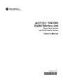
DIU3000
Digital Interface Unit
Phone Patch Interface
and E & M Console Interface
Owner’s Manual
68P02934C10-B
@6802934C10@
COMPUTER SOFTWARE COPYRIGHTS
The Motorola products described in this instruction manual may include copyrighted Motorola computer programs stored in semiconductor memories or
other media. Laws in the United States and other countries preserve for Motorola certain exclusive rights for copyrighted computer programs, including
the exclusive right to copy or reproduce in any form the copyrighted computer program. Accordingly, any copyrighted Motorola computer programs contained In the Motorola products described in this instruction manual may not be copied or reproduced in any manner without the express written permission of Motorola. Furthermore, the purchase of Motorola products shall not be deemed to grant either directly or by implication, estoppel. or otherwise.
any license under the copyrights, patents or patent applications of Motorola, except for the normal non-exclusive, royalty tree license to use that arises
by operation of law in the sale of a product.
EPS – 34440- B
This warranty applies within the fifty (50) United States, the District of Columbia and Canada.
LIMITED WARRANTY
MOTOROLA COMMUNICATION PRODUCTS
If the affected product is being purchased pursuant to a written Communications System Agreement signed by Motorola, the warranty contained in that
written agreement will apply. Otherwise, the following warranty applies.
I. WHAT THIS WARRANTY COVERS AND FOR HOW LONG:
Motorola Inc. or, if applicable, Motorola Canada Limited ("Motorola") warrants the Motorola manufactured radio communications product, including
original equipment crystal devices and channel elements ("Product"), against material defects in material and workmanship under normal use and
service for a period of One (1) Year from the date of shipment.
Motorola, at its option, will at no charge either repair the Product (with new or reconditioned parts), replace it with the same or equivalent Product
(using new or reconditioned Product), or refund the purchase price of the Product during the warranty period provided purchaser notifies Motorola
according to the terms of this warranty. Repaired or replaced Product is warranted for the balance of the original applicable warranty period. All
replaced parts of the Product shall become the property of Motorola.
This express limited warranty is extended by Motorola to the original end user purchaser purchasing the Product for purposes of leasing or for commercial, industrial, or governmental use only, and is not assignable or transferable to any other party. This is the complete warranty for the Product
manufactured by Motorola. Motorola assumes no obligations or liability for additions or modifications to this warranty unless made in writing and
signed by an officer of Motorola. Unless made in a separate written agreement between Motorola and the original end user purchaser, Motorola does
not warrant the installation, maintenance or service of the Product.
Motorola cannot be responsible in any way for any ancillary equipment not furnished by Motorola which is attached to or used in connection with the
Product, or for operation of the Product with any ancillary equipment, and all such equipment is expressly excluded from this warranty. Because each
system which may use the Product is unique, Motorola disclaims liability for range, coverage, or operation of the system as a whole under this warranty.
II. GENERAL PROVISIONS:
This warranty sets forth the full extent of Motorola’s responsibilities regarding the Product. Repair, replacement or refund of the purchase price, at
Motorola’s option, is the exclusive remedy. THIS WARRANTY IS GIVEN IN LIEU OF ALL OTHER EXPRESS WARRANTIES. MOTOROLA DISCLAIMS ALL OTHER WARRANTIES OR CONDITIONS, EXPRESS OR IMPLIED, INCLUDING THE IMPLIED WARRANTIES OR CONDITIONS OF
MERCHANTABILITY AND FITNESS FOR A PARTICULAR PURPOSE. IN NO EVENT SHALL MOTOROLA BE LIABLE FOR DAMAGES IN
EXCESS OF THE PURCHASE PRICE OF THE PRODUCT, FOR ANY LOSS OF USE, LOSS OF TIME, INCONVENIENCE, COMMERCIAL LOSS,
LOST PROFITS OR SAVINGS OR OTHER INCIDENTAL, SPECIAL, INDIRECT OR CONSEQUENTIAL DAMAGES ARISING OUT OF THE USE
OR INABILITY TO USE SUCH PRODUCT, TO THE FULL EXTENT SUCH MAY BE DISCLAIMED BY LAW.
III. HOW TO GET WARRANTY SERVICE:
Purchaser must notify Motorola’s representative or call Motorola’s Customer Response Center at 1-800-247-2346 within the applicable warranty
period for information regarding warranty service.
IV. WHAT THIS WARRANTY DOES NOT COVER:
A)
B)
C)
D)
E)
Defects or damage resulting from use of the Product in other than its normal and customary manner.
Defects or damage from misuse, accident, water, or neglect.
Defects or damage from improper testing, operation, maintenance, installation, alteration, modification, or adjustment.
Breakage or damage to antennas unless caused directly by defects in material workmanship.
A Product subjected to unauthorized Product modifications, disassemblies or repairs (including, without limitation, the addition to the Product of nonMotorola supplied equipment) which adversely affect performance of the Product or interfere with Motorola’s normal warranty inspection and testing
of the Product to verify any warranty claim.
F) Product which has had the serial number removed or made illegible.
G) Batteries (they carry their own separate limited warranty).
H) Freight costs to the repair depot.
I) A Product which, due to illegal or unauthorized alteration of the software/firmware in the Product, does not function in accordance with Motorola’s
published specifications or with the FCC type acceptance labeling in effect for the Product at the time the Product was initially distributed from Motorola.
J) Scratches or other cosmetic damage to Product surfaces that does not affect the operation of the Product.
K) That the software in the Product will meet the purchaser’s requirements or that the operation of the software will be uninterrupted or error-free.
L) Normal and customary wear and tear.
M) Non-Motorola manufactured equipment unless bearing a Motorola Part Number in the form of an alpha numeric number (i.e., TDE6030B).
V. GOVERNING LAW
In the case of a Product sold in the United States and Canada, this Warranty is governed by the laws of the State of Illinois and the Province of
Ontario, respectively.
VI. PATENT AND SOFTWARE PROVISIONS:
Motorola will defend, at its own expense, any suit brought against the end user purchaser to the extent that it is based on a claim that the Product or
its parts infringe a United States patent, and Motorola will pay those costs and damages finally awarded against the end user purchaser in any such
suit which are attributable to any such claim, but such defense and payments are conditioned on the following:
A) that Motorola will be notified promptly in writing by such purchaser of any notice of such claim;
B) that Motorola will have sole control of the defense of such suit and all negotiations for its settlement or compromise; and
C) should the Product or its parts become, or in Motorola's opinion be likely to become, the subject of a claim of infringement of a United States patent,
that such purchaser will permit Motorola, at its option and expense, either to procure for such purchaser the right to continue using the Product or its
parts or to replace or modify the same so that it becomes non-infringing or to grant such purchaser a credit for the Product or its parts as depreciated
and accept its return. The depreciation will be an equal amount per year over the lifetime of the Product or its parts as established by Motorola.
Motorola will have no liability with respect to any claim of patent infringement which is based upon the combination of the Product or its parts furnished hereunder with software, apparatus or devices not furnished by Motorola, nor will Motorola have any liability for the use of ancillary equipment
or software not furnished by Motorola which is attached to or used in connection with the Product. The foregoing states the entire liability of Motorola
with respect to infringement of patents by the Product or any its parts thereof.
Laws in the United States and other countries preserve for Motorola certain exclusive rights for copyrighted Motorola software such as the exclusive
rights to reproduce in copies and distribute copies of such Motorola software. Motorola software may be used in only the Product in which the software was originally embodied and such software in such Product may not be replaced, copied, distributed, modified in any way, or used to produce
any derivative thereof. No other use including, without limitation, alteration, modification, reproduction, distribution, or reverse engineering of such
Motorola software or exercise of rights in such Motorola software is permitted. No license is granted by implication, estoppel or otherwise under
Motorola patent rights or copyrights.
EPS – 48759 – O
All DIU's covered by the Warranty that require depot service must be sent or taken to the following depot:
Motorola System Support Center
1311 East Algonquin Road
Schaumburg, IL. 60196
1-800-221-7144
1-847-576-7300
FCC INTERFERENCE WARNING
The FCC Requires that manuals pertaining to Class A and Class B computing devices must contain warnings about possible interference with local residential radio and TV reception. This warning reads as follows:
NOTE: This equipment has been tested and found to comply with limits for a Class B digital device, pursuant to Part 15 of the FCC Rules. These limits
are designed to provide reasonable protection against harmful interference when the equipment is operated in a commercial or residential environment.
This equipment generates, uses, and can radiate radio frequency energy and, if not installed and used in accordance with the instruction manual, may
cause harmful interference to radio communications.
Trademarks
and Motorola are registered trademarks of Motorola Inc.
ASTRO, CENTRACOM, SmartZone, are trademarks of Motorola Inc.
IBM is a registered trademark of International Business Machines, Inc.
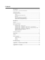
Contents
PART 1: PHONE PATCH INTERFACE
Model Complement ............................................................................................................ ii
Related Manuals ................................................................................................................ ii
DESCRIPTION ...................................................................................................... 1
INSTALLATION................................................................................................... 6
OPERATION ....................................................................................................... 16
TROUBLESHOOTING ....................................................................................... 20
APPENDIX A: Connectors and Cables ............................................................... 21
APPENDIX B: Acronyms.................................................................................... 22
PART 2: E & M CONSOLE INTERFACE
Performance Specifications ............................................................................................... ii
Related Manuals ................................................................................................................. ii
DESCRIPTION ...................................................................................................... 1
INSTALLATION................................................................................................... 4
OPERATION ....................................................................................................... 14
TROUBLESHOOTING ....................................................................................... 18
APPENDIX A: Connectors and Cables ............................................................... 19
APPENDIX B: Acronyms.................................................................................... 20
PART 1:
Phone Patch Interface
Contents
Description........................................................................................... 1
Scope of Part 1 – Phone Patch Interface ............................................................... 1
General Description............................................................................................... 1
Functional Description .......................................................................................... 2
General ...................................................................................................................... 2
Call Initiation and Establishment .............................................................................. 2
Half Duplex Operation .............................................................................................. 3
Outbound Transmission Mode .................................................................................. 3
DIU Audio Routing................................................................................................... 3
Console Take Over.................................................................................................... 4
Go–Ahead Tone ........................................................................................................ 4
Signal Description ..................................................................................................... 4
Inst allation ........................................................................................ 6
General .................................................................................................................. 6
Electrical Connections........................................................................................... 7
Programming the DIU ........................................................................................... 8
CHANGE/VIEW : ASTRO System.......................................................................... 8
CHANGE/VIEW : Cons&Mics : MRTI Phone Patch .............................................. 9
CHANGE/VIEW : Tx Default Attributes : Interconnect/phone Patch ................... 10
CHANGE/VIEW : CONS&MICS : TRC CONSOLE............................................ 13
Parameter Check List .............................................................................................. 13
Testing the Installation ........................................................................................ 14
Operation........................................................................................... 16
General ................................................................................................................ 16
Menu Commands ................................................................................................ 16
Modified Menu Tree ............................................................................................... 16
Activity.................................................................................................................... 18
MRTI (MRTI Telephone Interconnect) .................................................................. 18
Troubles hooting................................................................................. 20
Appendix A: Connectorsand Cables .............................................. 21
Appendix B: Acronyms..................................................................... 22
Land Mobile Products Sector
1301 E. Algonquin Road, Schaumburg, IL 60196
Copyright © 2003 Motorola all rights reserved
68P02934C10-B
April, 2003
PHONE PATCH INTERFACE
MODEL COMPLEMENT
FKN4389A
MRTI Adaptor cable (used with MRTI 1000 or MRTI 2000 only)
68P02934C10
ASTRO DIU Phone Patch Interface and Local Desk Set Interface Owner’s manual (this manual)
RELATED MANUALS
68P02949C65
DIU3000, Owner’s Manual
68P02924C15
ASTRO DIU RSS, User’s Manual
68P02949C75
DIU3000, Service Manual
68P81090E45
Encryption Cartridge, User Manual (Models T5371, T5373, T5375)
68P81090E50
Encryption Cartridge, User Manual (All Models)
68P80801G85
Universal Crypto Module, Instraction Manual (Model T6721)
68P81090E85
Encryption Cartridge, Service Manual (Models T5371, T5373, T5375)
68P81090E95
Encryption Cartridge, Service Manual (All Models)
68P80801G90
Universal Crypto Module, Service Manual (Model T6721)
68P02949C70
CENTRACOM Signalling Link, Owner’s Manual
68P02949C95
DIU3000 Trunking Operation Option, Owner’s Manual
ii
Description
1
Desc
ription
Scope of Part 1 – Phone Patch Interface
This manual provides instructions for connecting the DIU to a Telephone
Inteconnect system, programming the DIU Phone Patch interface and operating it.
For a complete description of the DIU refer to the DIU3000 Owner’s Manual
68P02949C65. In addition, for the customer convenience, this manual covers all
other aspects of connecting the Telephone Interconnect to the DIU, even if
previously covered in other DIU manuals.
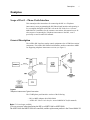
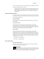
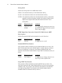
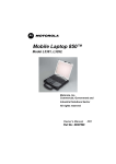
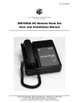
General Description
The ASTRO DIU interfaces analog control equipment to the ASTRO base station/
comparator. The ASTRO DIU Phone Patch Interface enables connection to MRTI
for supporting telephone interconnect services (see Figure 1).
.
DIU
Figure 1
Telephone Interconnect Typical Connection
The C54BF phone patch interface consists of the following:
– DIU to MRTI Adaptor cable FKN4389A
– ASTRO DIU Phone Patch Interface manual 68P02934C10 (this manual)
Note: C54 is no longer available.
C54 was necessary when interfacing the DIU to a MRTI 1000 or MRTI 2000.
The MRTI 1000 and MRTI 2000 are cancelled, and the replacement product is the Zetron Model 30.
2
Phone Patch Interface Owner’s Manual
Functional Description
General
The DIU is an interface between the ASTRO fixed equipment (infrastructure) and
the analog control equipment. The DIU converts the analog voice from the analog
control equipment into digital format and passes it to the fixed equipment. In the
opposite direction, it converts the voice coming from the fixed equipment in
digital format into analog and passes it to the analog control equipment. The DIU
also incorporates the encryption/decryption capability to allow for secure
communications.
The DIU Phone Patch Interface extends the above–mentioned DIU capabilities
and interconnects to a public telephone service via the Motorola MRTI Telephone
Interconnect.
Call Initiation and Establishment
An interconnect call may be initiated by a subscriber or a landline user. A landline
user (i.e telephone user) initiates a call by dialing into the Telephone Interconnect
device (MRTI). A subscriber initiates a call by transmitting the MRTI access
code. The DIU role, as described in the subsequent sections, is transferring the
analog signals and voice to/from MRTI.
Subscriber Initiated Call
A subscriber initiates an interconnect call by transmitting an access code to the
Telephone Interconnect device. Upon receiving its access code, the MRTI
accesses the telephone line, activates the MRTI PTT and then the subscriber hears
the dial tone. When the dial tone is heard, the subscriber may enter a telephone
number. When the called party answers, an interconnect call is established.
At the end of the conversation the subscriber transmits the disconnect code to the
Telephone Interconnect.
Landline Initiated Call
A landline user (i.e phone user) initiates a call by dialing into the Telephone
Interconnect. As a response, the patch activates a PTT and sends a ring tone,
without answering the telephone line. If ringing to the patch is allowed to continue
for 1 minute, it will answer the phone line momentarily in an attempt to release
the calling party to prevent locking up the phone line. Once the subscriber
answers the phone ring, by sending the access code, the call is established and
proceeds in the same way as the call initiated by the subscriber (see “Subscriber
Initiated Call” section above).
Half Duplex Operation
Once an interconnect session is established, the phone–patch receives the control
over the outbound capability of the system and potentially holds it for the duration
Description
3
of the session. In order to reduce voice truncation in the ASTRO modes, the DIU
operates in a half duplex mode, as follows:
– The DIU terminates the Telephone Interconnect outbound transmission (even
though MRTI PTT is activated) as soon as the subscriber inbound activity is
detected; MRTI outbound transmission is re–enabled when the inbound
reception ends.
Outbound Transmission Mode
The Telephone Interconnect outbound transmission mode and key are determined
according to the Slaving mode (defined by the DIU RSS). There are three slaving
modes: Strap, Slave and Steer.
Strap (fixed) Mode
In this slaving mode, the outbound transmission mode and key are fixed (set by
the DIU RSS).
Slave (inherit) Mode
In this slaving mode, the mode and key of the interconnect session initial
outbound transmission, is determined by the Default Mode and Key defined by
the DIU RSS. As the session proceeds, the outbound attributes (mode and key) are
inherited from the last inbound reception from the subscriber.
Steering Mode
In this slaving mode, the mode and key of the interconnect session initial
outbound transmission, is determined by the Default Mode and Key defined by
the DIU RSS. As the session proceeds, the outbound attributes (mode and key) are
inherited from the last inbound reception, but only if its security level is equal or
higher than the previous reception. The following mode transitions are allowed:
• Analog Clear Þ Astro Clear
• Analog Clear Þ Astro Encrypted
• Astro Clear Þ Astro Encrypted
DIU Audio Routing
Subscriber Inbound Audio
Subscriber inbound audio is routed in an analog form, to both the console and
Telephone Interconnect inbound interfaces.
.
IMPORTANT
Note
If the subscriber call is in Astro mode, its audio is decoded from Astro
clear or Encrypted into the analog form. Therefore, even if the inbound
audio is secure, it is routed to the MRTI in clear analog form.
4
Phone Patch Interface Owner’s Manual
Telephone Interconnect Outbound Audio
The telephone interconnect output audio is transmitted to the base station. If the
mode of the interconnect session is Astro clear or Astro encrypted, the telephone
interconnect outbound audio is encoded by the DIU into the Astro infrastructure
signalling. The telephone interconnect outbound audio is also routed in an analog
form, to the console.
Console Take Over
The DIU provides a console take over capability that allows a dispatcher to take
over the DIU resources (according to console's defined mode and key), while an
interconnect call is in progress. Once a console PTT is detected, the DIU
terminates the MRTI outbound transmission (even though MRTI PTT is
activated). The MRTI outbound transmission is resumed (in the previous mode
and key) as soon as the console PTT is released.
Go–Ahead Tone
The Go–Ahead tone indicates that the subscriber has dekeyed and the landline
party may proceed with the conversation. The Go–Ahead tone is generated by the
MRTI in both Astro and Analog sessions. The DIU does not generate the Go–
ahead tone.
Signal Description
This section contains a brief description of the logic interface between the DIU
and the MRTI. For a detailed description of the interface signals, refer to the
MRTI Instruction manual.
– MRTI PTT. This signal is continuously activated by the MRTI for the
duration of the telephone conversation.
– PATCH INHIBIT. This input signal to MRTI completely disables the
MRTI. When activated, patch inhibit drops any accessed lines. The telephone
interconnect is re–enabled when the PATCH INHIBIT input is reset. This
line is activated by the DIU upon reception of the “Patch Inhibit On"
command from the console and released upon reception of the “Patch Inhibit
Off" command from the console.
– RECEIVER LOGIC CARRIER INDICATOR (DIU call detect). This
input to the MRTI indicates that an inbound call is active, and it is required
for the following purposes:
• Switching the audio paths within MRTI during a telephone conversation.
• Resetting the subscriber timer (Mobile Inactivity Control) – the patch
disconnects if the subscriber is inactive for a period of time defined by a
MRTI parameter.
• Detecting control commands from the subscriber. The subscriber can send
control commands by “stretching" the first digit or by pushing PTT for one
second before sending the first control signalling digit.
Description
5
– INBOUND AUDIO. An analog line used by the DIU for transferring audio
to the telephone interconnect.
– OUTBOUND AUDIO. An analog line used by the DIU for receiving audio
from the telephone interconnect.
.
Note
MRTI (analog and digital inbound), Console (analog and digital
inbound) and Base Station (analog outbound) audio levels may be set
in RSS or from the front panel display (after entering service mode,
password: 039302164). Each interface may be changed by 20 dB in
1 dB increments. Because the DIU passes and generates voice and
tones at various levels, there is no absolute output level as suggested
by the term 'dBm' on the front panel display. The term 'dBm' that
accompanies gain settings in RSS and the front panel display should
be interpreted as a rough estimate of signal output. In other words, the
output level display should be thought of as a volume gain control, not
as an absolute level indicator. The exact output, in dBm, is a function of
1) the source level, 2) the output level setting and 3) the averaging
method used to measure the signal.
6
Phone Patch Interface Owner’s Manual
Installation
General
This chapter provides connection and setup instructions for the DIU Phone Patch
Interface. It is suggested to perform the instructions sequentially. The following
are the general steps:
• Electrical connections
• Programming the DIU for operation with the phone patch interface.
• Testing the installation.
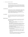
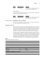
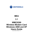
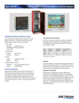
Generic MRTI Connection Diagram
Figure 2 describes the generic MRTI connection diagram.
Ground
Call Detect COR *
Inbound Phone, TX Audio *
Outbound Phone, TX Audio *
Patch Inhibit **
MRTI PTT
* Zetron reference
** Not supported with Zetron
Figure 2
Generic MRTI Connection Diagram
Installation
7
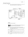
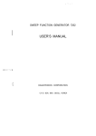
Electrical Connections
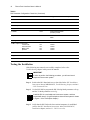
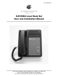
Step 1. Solder the MRTI multiconductor cable conductors, to the 9–pin D–Type
connector supplied with the DIU, according to Figure 3.
.
.
Figure 3
DIU to MRTI Interconnect Diagram
If you are using non–standard cables, ensure that their length does not
exceed the original length of the supplied cables.
Note
Step 2. Solder a wire (not included), between pin 7 of the 9–pin D–Type
connector supplied with the DIU, and pin 3 of the optional plug supplied
with the MRTI, according to Figure 3.
Step 3. Connect the soldered connector to the MRTI Adaptor cable supplied
with the DIU.
Step 4. Connect the MRTI Adaptor cable to the PATCH connector on the DIU
rear panel.
Step 5. Connect the chassis mounted stud of MRTI to the protective ground.
Step 6. Connect the G terminal of the DIU's Console TB to the protective
ground.
8
Phone Patch Interface Owner’s Manual
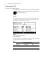
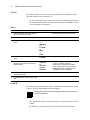
Programming the DIU
CHANGE/VIEW : ASTRO System
This section describes the parameters specific for the DIU Phone Patch Interface.
.
For a description of the complete DIU programming, refer to the DIU
RSS manual 68P02924C15.
Note
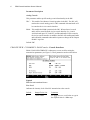
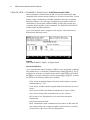
General
The ASTRO SYSTEM is a data entry screen used to customize the DIU to the
ASTRO system in which the DIU is installed (see Figure 4). Other RSS screens
are affected by the selections made in this screen.
.
Figure 4
ASTRO System Parameters Screen
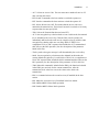
System Limitations
The DIU supports up to two consumers (analog devices) at a time. The following
table lists all the possible combinations of two consumers:
Table 1
Consumers (Analog Devices)
Console
1
•
2
•
3
DIU Handset
MRTI
•
•
•
•
Installation
9
Parameter Description
MRTI Phone Patch
Disables/selects support mode of the MRTI Phone Patch.
Default
Range/Choice List
Set to:
Comments
DISABLE
ENABLE/DISABLE ENABLE Use arrows to toggle between
the choices.
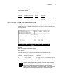
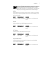
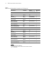
CHANGE/VIEW : Cons&Mics : MRTI Phone Patch
MRTI Phone Patch is a data entry screen, used to change/view the intensity level
and PTT polarity of the MRTI Phone Patch (see Figure 5). These parameters are
described below.
.
Figure 5
MRTI Phone Patch (Interfaces) Screen
Line Level
Indicates the intensity level of the DIU transmission to the phone patch.
Default
Range/Choice List
Comments
0
-20 to 0 dBm
Use [^]/[|] arrows to scroll value or type in
the required value in 1 dBm steps.
.
Note
Because the DIU passes and generates voice and tones at various
levels, it is not possible to set an absolute output level. The output level
setting should be thought of as a volume gain control. The exact
output, in dBm, is a function of: 1) the source level, 2) the output level
setting and 3) the averaging method used to measure the signal.
10
Phone Patch Interface Owner’s Manual
Silent Level
Defines the Silent Level allowable range.
Default
Range/Choice List
Comments
5
0 to 255
Use [^]/[|] arrows to scroll value or type in
the required value.
PTT Polarity
Selects the polarity of the MRTI PTT signal.
Default
Range/Choice List
Comments
LOW
LOW / HIGH
Use [^]/[|] arrows to scroll between the
choices.
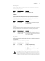
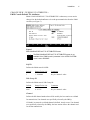
CHANGE/VIEW : Tx Default Attributes : Interconnect/phone Patch
The INTERCONNECT/PHONE PATCH DEFAULT TX ATTRIBUTES is a data
entry screen used to change/view the default attributes for interconnect/phone
patch (see Figure 6).
.
To access this screen, on the ASTRO SYSTEM parameters screen,
set the MRTI Phone Patch parameter to ENABLE.
Note
Figure 6
INTERCONNECT/PHONE PATCH DEFAULT TX ATTRIBUTES Screens
Self ID
This parameter defines the source ID used in transmissions initiated by the phone
patch.
Installation
11
Talk Group ID
Defines the DIU Talk Group ID that will be used as a default for transmissions
initiated by the phone patch.
Default
Range/Choice List
Comments
4095
0 - 65535
Key in a numeric value
Channel
Defines the RF channel number that will be used as a default for transmission.
If “blanks" are entered, no default channel is defined. In such a case, the base
station will use the channel used for the last transmission.
Default
Range/Choice List
Comments
blank
0 - 255, blank
Use [^]/[|] arrows to scroll value or type in
the required value.
Tx Mode
Defines the initial interconnect transmission mode that will be used. The mode of
subsequent transmissions will be determined by the Slaving Mode parameter.
Default
Range/Choice List
Clear
Analog/(ASTRO)Clear/ Press [Shift] and [?] to display the choices in a
(ASTRO) Coded
pop–up window. Then scroll to the required
choice and press [Enter].
Comments
Key Number
Defines the encryption key number that will be used as a default for transmission
from the MRTI.
If “blanks" are entered, no default key is defined.
Default
Range/Choice List
Comments
blank
0 - 511, blank
For EMC configuration PID
blank
1 - 65439, blank
For EMC configuration CKR
Use [^]/[|] arrows to scroll value or type in
the required value.
.
Leaving this field as “blank” may result in a transmission failure.
A transmission failure will happen if the default transmit mode is
Coded, no default key is selected, and there has been no previous
Warning encrypted call handled by the DIU when the phone patch keys up.
!
12
Phone Patch Interface Owner’s Manual
Slaving Mode
Defines the slaving mode for the MRTI Phone Patch:
STRAP –The transmission always is the default mode and key.
SLAVE– The transmission follows the last inbound mode and key.
STEER– The transmission follows the last inbound mode and key so that mode
upgrades are achieved (analog to digital clear, analog to digital coded,
digital clear to digital coded), but the transmission mode is never
downgraded.
Default
Range/Choice List
Comments
STRAP
STRAP/SLAVE/
STEER
Press [Shift] and [?] to display the choices in a
pop–up window. Then scroll to the required
choice and press [Enter].
DTMF Output Port Connected to Console W/L, E&M Console, MRTI
Patch, Speaker
Defines the potential DTMF audio destination for each of the above.
Default
Range/Choice List
Comments
YES
YES/NO
Use [^]/[|] arrows to scroll.
Standard DTMF Tone Duration
This parameter defines the duration of the standard DTMF tone (on–time). The
DIU off–time (time between two DTMF digits) is constant and set to 100 msec.
The user can adjust the on–time only. Note that the Standard DTMF Tone
Duration value should be smaller than the Long DTMF Tone Duration value (see
below).
Default
Range/Choice List
Comments
100 ms
50 to 3000 ms
Use [^]/[|] arrows to change value in 10 ms
steps or type in the required value.
Long DTMF Tone Duration
This parameter defines the duration of the long DTMF tone (on–time). The
subscriber instructs the DIU what DTMF duration to use for the current dialing:
standard or long. The off–time is not affected by the DTMF on–time duration.
Note that the Long DTMF Tone Duration value should be higher than the
Standard DTMF Tone Duration value (see above).
Installation
13
Default
Range/Choice List
Comments
100 ms
50 to 3000 ms
Use [^]/[|] arrows to change value in 10 ms
steps or type in the required value.
Pause Duration
This parameter defines the time delay the DIU waits to dial the next DTMF digit
when the “pause" DTMF digit is received.).
Default
Range/Choice List
Comments
1000 ms
500 to 4000 ms
Use [^]/[|] arrows to change value in 500 ms
steps or type in the required value.
CHANGE/VIEW : CONS&MICS : TRC CONSOLE
The HLGT Duration parameter range is limited to 120 - 5000 ms (as opposed to
60 - 5000) when the phone patch interface is used.
Parameter Check List
This section contains a check–list of all the parameters that the user has to check/
change in order to configure the DIU for the telephone interconnect operation. It
is assumed that all other DIU parameters not related to the telephone interconnect
operation are programmed according to the ASTRO DIU RSS User's manual
68P02924C15. The table contains the path in the RSS menu tree leading to the
screen that contains the parameter, the parameter default value, and the range of
values the parameter can have. If it is necessary to change the parameter value, the
user can record the new value in the “Required" column. After all the parameters
in the table are checked/changed, the user can proceed to the actual parameters
programming, using the DIU RSS computer program. The user can use the last
column in the table to mark with a “" each parameter already programmed.
Table 2
DIU Parameter Configuration Check-List
Parameter Path / Name
Default
Range
Required
Disable
Enable/Disable
Enable
CHANGE/VIEW : Astro System Parameters
MRTI Phone Patch
CHANGE/VIEW : CONS & MICS : MRTI Phone Patch
Line Level
0
-20 to 0
Silent Level
5
0 - 255
PTT Polarity
Low
Low / High
CHANGE/VIEW : CONS & MICS : TRC Console
HLGT Duration
120
60 - 5000 ms
³120 ms
!
14
Phone Patch Interface Owner’s Manual
Table 2
DIU Parameter Configuration Check-List (Continued)
Parameter Path / Name
Default
Range
Required
!
CHANGE/VIEW : TX DEFAULT ATTRIBUTES : Interconnect/Phone Patch Default Tx Attributes
Self ID
5
1 - 9999999
Talk Group ID
4095
0 - 65535
Channel
blank
0 to 255, blank
Tx Mode
Clear
Analog/(ASTRO)Clear/
(ASTRO) Coded
Key Number
blank
0 - 511, or 1 - 65439,
blank
Slaving Mode
STRAP
STRAP/SLAVE/STEER
DTMF Output Connected to:
Console W/L
E & M Console
MRTI Patch
Speaker
Yes
Yes
Yes
Yes
Yes/No
Yes/No
Yes/No
Yes/No
Standard DTMF Tone Duration
100 ms
50 to 3000 ms
Long DTMF Tone Duration
100 ms
50 to 3000 ms
Pause Duration
1000 ms
500 to 4000 ms
Testing the Installation
If the following test cannot be successfully completed, refer to the
Troubleshooting chapter in this part of the manual.
.
IMPORTANT
Note
In order to perform the following procedure, you will need a real
telephone interconnect system.
Step 1. Perform the DIU functional tests, as described in the DIU Installation
Instructions Manual 68P02920C65, Troubleshooting chapter, section 6
– DIU Functional Tests.
Step 2. Use the DIU RSS to program the DIU Slaving Mode parameter to Strap,
and the Tx Mode parameter to Analog.
.
Install the DIU in a real telephone interconnect system, and then
proceed with step 3. (A typical telephone interconnect system is shown
in Figure 1 of the Description chapter.)
Note
Step 3. Verify that the DIU link to the base station/comparator is established
(refer to the DIU Installation Instructions Manual 68P02920C65,
Installation chapter, section 6.1 – DIU Power–On).
Installation
15
Step 4. Connect the MRTI to a PSTN using the MRTI connector, line 1. Verify
that all MRTI LEDs are off.
Step 5. Initiate voice transmission from the subscriber (a regular analog or
digital, not an interconnect transmission). Verify that the MRTI's
1
RADIO BUSY LED is on, as long as the subscriber PTT is active.
Step 6. Set the subscriber to analog mode.
Step 7. Send the MRTI connect command from the subscriber (the default key is
1
“”). Verify that the MRTI's RADIO BUSY LED turns on and then off,
2
3
and then the MRTI's CONNECT, TX and PL STRIP LEDs turn on.
The dial tone is heard in the subscriber.
Step 8. Dial a number of a nearby phone from a subscriber.
Step 9. Verify that the interconnection with the subscriber works properly (no
noises or interruptions occur during the conversation). Also verify, that
2
3
the MRTI's CONNECT, TX and PL STRIP LEDs are continuously on,
1
while the RADIO BUSY turns on only when the subscriber presses PTT.
Step 10. Send the MRTI release command from the subscriber (the default key is
4
“#"). Verify that all MRTI LEDs are turned off.
Step 11. Initiate a landline call by dialing to the MRTI. Verify that the MRTI
2
CONNECT LED turns on during the ring tones and off, during the
3
pauses. The MRTI's TX and MONITOR LEDs turn on for several
seconds,and then turn off. The ringing tones are heard in the subscriber.
Step 12. Send the MRTI connect command from the subscriber (the default key is
1
““). Verify that the MRTI's RADIO BUSY LED turns on and then off,
and then the MRTI's CONNECT, TX and PL STRIP LEDs turn on.
Step 13. Verify that the interconnection with the subscriber works properly (no
noises or interruptions occur during the conversation). Also verify, that
3
the MRTI's CONNECT,2 TX and PL STRIP LEDs are continuously on,
while the RADIO BUSY turns on, only when the subscriber presses
PTT.
Step 14. Send the MRTI release command from the subscriber (the default key is
4
“#"). Verify that all MRTI LEDs are turned off.
Step 15. Use the DIU RSS to program the DIU Slaving Mode parameter to Strap,
and the Tx Mode parameter to Clear.
Step 16. Set the subscriber to Astro mode.
Step 17. Repeat steps 3, and 7 through 14.
1
2
3
4
Refer to Zetron "Carrier LED"
Refer to Zetron "Phone LED"
Zetron does not have an equivalent LED for PL Strip and Monitor
Zetron does not support "#" or Patch Inhibit
16
Phone Patch Interface Owner’s Manual
Operation
General
All the DIU operating instructions covered by the DIU3000 Owner's manual
68P02949C65 are applicable to the DIU equipped with a telephone Interconnect.
In addition, this chapter provides instructions for using the telephone Interconnect
specific features.
Menu Commands
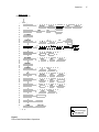
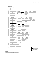
Modified Menu Tree
The parameters and functions accessed via the MENU/ESC key are organized in
a tree-like structure, or a “menu", shown in Figure 7. The menu operations related
to the telephone interconnect are emphasized, while the standard DIU operations
(covered in the DIU3000 Owner's manual) are shaded.
Operation
17
.
READY STATE
(TIME OF DAY DISPLAY)
ACTIVITY
BASE
INBOUND
DBM
E AND M
MRTI
USER
CONSOLE
SLNT
AGC
AUTO
CLOCKSET
CONSOLE
ID
MRTI
DBM
ID
E AND M
AUTO
DBM
ID
DBM
MAINT
USER
ID
MICSNS
TIME FMT
LIGHT
CONTRS
MAINT
USER
CRYPTO
MAINT
USER
CRYPTO
EDITPSWD
SLNT
AGC
AGC
SLNT
AUTO
CRYPTO
ERR LIST
HANDSET
LCD
LOGIN
LOGOUT
SERVICE
TESTS
TX PARAMS
OTAR
LOGIN
LOGOUT
AUD LOOP
ACCS
RKEY REQ
LEGEND
Use arrows [^]/[|]
Use [ENTR] key
Figure 7
Phone Patch Related Menu Operations
18
Phone Patch Interface Owner’s Manual
Activity
This menu provides a means of monitoring transmit/receive parameters of the
DIU and control devices connected to it.
– For the MRTI (MRTI telephone interconnect), the CHaNneL and MODE
parameters of the current transmission can be traced. If not currently
transmitting, the last active parameters are displayed.
Table 3
Action
LCD Display
1. While in the ready mode, press MENU/
ESC to enter the menu mode.
The last accessed menu entry is shown.
2. Scroll until ACTIVITY is shown.
ACTIVITY
3. Press ENTR to enter the device selection
menu.
CONSOLE
or
INBOUND
or
E AND M
or
MRTI
or
USER
4. Scroll to display the required device
option.
5. Press ENTR to display activity
parameters that can be traced for the
selected device.
Comments
MRTI
CHNL nnn
or
ANALOG/
CLEAR/
ENCR nnn
•
•
The data displayed is updated once a
second, or if ENTR is pressed.
If there was no inbound process since
power–up and ENTR is pressed while in
INBOUND ACTIVITY display state, the
message NO INFO is displayed.
6. Use the arrow keys to scroll between the
available parameters.
7. Press MENU/ESC to return to the ready
state.
MRTI (MRTI Telephone Interconnect)
This menu controls the parameters of the communication interface to the
telephone interconnect. The following parameters can be changed:
.
Changing the telephone interconnect interface parameters requires
entering the Service password, “039302164”.
Note
– Line signal level. The line signal level can be set within the range of –20 to
0 dBm.
– ID. Enables viewing the phone patch ID.
Operation
19
– AGC. This parameter adjusts the silent level of the MRTI port AGC (i.e. it
sets the activation point of the MRTI AGC for outbound speech).
Note
MRTI (analog and digital inbound), Console (analog and digital
inbound) and Base Station (analog outbound) audio levels may be set
in RSS or from the front panel display (after entering service mode,
password: 039302164). Each interface may be changed by 20 dB in
1 dB increments. Because the DIU passes and generates voice and
tones at various levels, there is no absolute output level as suggested
by the term 'dBm' on the front panel display. The term 'dBm' that
accompanies gain settings in RSS and the front panel display should
be interpreted as a rough estimate of signal output. In other words, the
output level display should be thought of as a volume gain control, not
as an absolute level indicator. The exact output, in dBm, is a function of
1) the source level, 2) the output level setting and 3) the averaging
method used to measure the signal.
Table 4
Action
LCD Display
1. While in the ready mode, press MENU/
ESC to enter the menu mode.
Comments
The last accessed menu entry is shown.
2. Scroll until MRTI is shown.
MRTI
3. Press ENTR to display the options.
DBM nn
or
ID HHH
or
AGC
NOTE
The setting of AGC has no effect on DIU operation with MRTI.
4. Scroll to display the required option.
ID HHH shows the console ID in hexadecimal
format
5. If changing/viewing of line signal level is not required, skip to step 10.
6. Scroll to select the DBM option.
DBM nn
“nn” indicates the currently selected signal
level in dBm units.
7. Press ENTR.
DBM nn
“nn” blinks.
8. Scroll to select the required value.
DBM mm
“mm” indicates the new selected signal level.
9. Press ENTR to confirm the selection.
DBM mm
10. Press MENU/ESC twice to return to the
ready state.
8 : 46 : 16
20
Digital Interface Unit Owner’s Manual
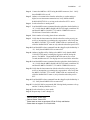
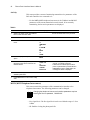
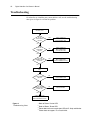
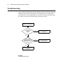
Troubleshooting
If a subscriber or a landline party cannot initiate a call, use the troubleshooting
chart given in Figure 8 to isolate the problem.
.
PERFORM SUBSCRIBER
INITIATED CALL
4
IS THE
PATCH INHIBIT
LED ON?
YES
CHECK THE DIU TO
MRTI CONNECTION
(PATCH INHIBIT LINE)
NO
CHECK THE DIU TO
MRTI CONNECTION
(CALL DETECT LINE)
YES
CHECK THE DIU TO
MRTI CONNECTION
(AUDIO FROM MRTI TO DIU)
NO
CHECK THE MRTI TO
PSTN CONNECTION
NO
1
IS THE
RADIO BUSY
LED ON?
YES
2
ARE THE
CONNECT AND TX
LEDS ON?
NO
PERFORM LANDLINE
CALL
2
IS THE CONNECT
LED ON?
YES
3
DO THE TX AND
MONITOR LEDS TURN
ON AND OFF?
NO
CHECK THE MRTI
YES
CHECK THE DIU TO
MRTI CONNECTION
(AUDIO FROM MRTI TO DIU)
Figure 8
Troubleshooting Chart
1
Refer to Zetron "Carrier LED"
2
Refer to Zetron "Phone LED"
Zetron does not have an equivalent LED for PL Strip and Monitor
Zetron does not support "#" or Patch Inhibit
3
4
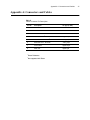
Appendix A: Connectors and Cables
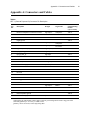
Appendix A: Connectors and Cables
Table 5
Patch Connector Pin Description
.
Pin No.
Description
I/O Type (in DIU)
1
Patch Ground
2
Not used
3
Not used
4
Call Detect, COR1
digital output
1
5
Inbound Phone, TX Audio
analog output
6
Outbound Phone, RX Audio
7
Patch Inhibit
8
MRTI PTT
1
2
1
Zetron Reference
2
Not supported with Zetron
analog input
digital output
digital input
21
22
Phone Patch Interface Owner’s Manual
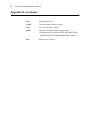
Appendix B: Acronyms
DIU
Digital Interface Unit
DTMF
Dual Tone Multi-Frequency (signal)
EMC
Encryption Module Cartridge
MRTI
Microprocessor Radio Telephone Interconnect
(Acronym used to reference MRTI 1000, MRTI 2000,
or Zetron Model 30 Telephone Interconnect device)
RSS
Radio Service Software
PART 2:
E & M Console
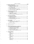
Contents
Description ........................................................................................... 1
Scope of Part 2 – E & M Console Interface .......................................................... 1
General Description............................................................................................... 1
Functional Description .......................................................................................... 2
General ...................................................................................................................... 2
Transmission from E & M Console .......................................................................... 2
Reception................................................................................................................... 2
Half and Full Duplex Operation Support .................................................................. 2
E & M Console Feature Enhancement...................................................................... 2
E & M Console Logic Signal Description ................................................................ 3
Installation ........................................................................................... 4
General .................................................................................................................. 4
Electrical Connections........................................................................................... 4
Programming the DIU ........................................................................................... 5
CHANGE/VIEW : ASTRO System.......................................................................... 5
CHANGE/VIEW : CONS&MICS : E&M Console : Console Interfaces................. 6
CHANGE/VIEW : CONS&MICS : E&M Console : E&M Functionality Table ..... 8
CHANGE/VIEW : TX DEFAULT ATTRIBUTES :
E&M Console Default TX Attributes ..................................................................... 11
Parameter Check List .............................................................................................. 12
Testing the Installation ........................................................................................ 13
Operation ........................................................................................... 14
General ................................................................................................................ 14
Menu Commands ................................................................................................ 14
Modified Menu Tree ............................................................................................... 14
Activity.................................................................................................................... 16
E and M ................................................................................................................... 16
Troubleshooting................................................................................. 18
Appendix A: Connectors and Cables .............................................. 19
Appendix B: Acronyms..................................................................... 20
E & M CONSOLE INTERFACE
PERFORMANCE SPECIFICATIONS
Parallel E & M console
Up to 3
Base station and DIU Control Support
Available using customer supplied external switches.
Specifications are subject to change without notice.
RELATED MANUALS
68P02949C65
DIU3000, Owner’s Manual
68P02924C15
ASTRO DIU RSS, User’s Manual
68P02949C75
DIU3000, Service Manual
68P81090E45
Encryption Cartridge, User Manual (Models T5371, T5373, T5375)
68P81090E50
Encryption Cartridge, User Manual (All Models)
68P81090E85
Encryption Cartridge, Service Manual (Models T5371, T5373, T5375)
68P81090E95
Encryption Cartridge, Service Manual (All Models)
68P02949C70
CENTRACOM Signalling Link, Owner’s Manual
68P02949C95
DIU3000 Trunking Operation Option, Owner’s Manual
ii
Description
1
Description
Scope of Part 2 – E & M Console Interface
This manual provides instructions for connecting the DIU to a E & M Console,
programming the DIU E & M Console interface and operating it. For a complete
description of the DIU, refer to the DIU3000 Owner’s manual 68P02949C65. In
addition, for the customer's convenience, this manual covers all other aspects of
connecting the E & M Console to the DIU, even if they are already covered in
other DIU manuals.
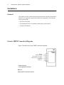
General Description
The ASTRO DIU interfaces analog control equipment to the ASTRO base station/
comparator (see Figure 1).
.
DIU
E&M
CONSOLE
Figure 1
E & M Console Typical Connection
2
E&M Console Interface Owner’s Manual
Functional Description
General
The DIU E & M Console Interface allows the E & M Console to be used as a
dispatch point. The DIU converts the analog voice from the E & M Console into
digital format and passes it to the fixed equipment. In the opposite direction, it
converts the voice coming from the fixed equipment in digital format into analog,
and passes it to the E & M Console. The DIU also allows for secure
communications between the E & M Console operator and the ASTRO fixed
equipment.
The DIU supports base station control and DIU control from the E & M Console
via discrete logic inputs. Supporting these functions requires external switches,
defined in this manual, which should be provided by the customer.
Transmission from E & M Console
The E & M Console initiates transmission by activating its PTT output. The DIU
keys up the base and routes the audio from the E & M Console to the base station
and to additional consumers connected to the DIU.
Reception
The DIU routes the inbound voice to the defined consumers, including the E & M
Console.
Half and Full Duplex Operation Support
The DIU supports E & M Consoles configured for both half and full duplex
operation. E & M Consoles connected in parallel to the DIU should be configured
for a half duplex mode.
E & M Console Feature Enhancement
Similarly to all consumers, the DIU RSS defines the default TX attributes for the
E & M Console. In addition, the DIU provides two logic inputs that can be used
by the E & M Console for sending base station and DIU control commands. The
use of these inputs requires external switches, as defined in the INSTALLATION
chapter of this manual. The external switches have to be provided by the customer
(see also Figure 2).
Description
3
.
Figure 2
External Logic for Enhanced DIU Control
Two logic inputs enable four logic combinations, each of which may serve as a
Function REQuest (FREQ) and execute base station and DIU control commands.
These commands are associated to a logic combination via the DIU RSS. A
setting of a TX attribute controlled by a logic combination overrides the default
setting of this attribute defined by the RSS.
If external switches are not installed, the DIU interprets both logic inputs as being
high. This combination may be used as a legal function request in the RSS, thus
expanding the control over the default TX attributes.
E & M Console Logic Signal Description
This section contains a brief description of the logic interface between the DIU
and the E & M Console. For a detailed description of the interface signals, refer to
the E & M Console Instruction manual.
– PTT. This signal is activated when the E & M Console operator presses
either the TRANSMIT key or the handset PTT, in order to initiate
transmission.
– REPEAT DISABLE/ENABLE. This signal is activated when the console
operator presses the Repeat Disable key, in order to disable (or enable) repeat
operation.
4
E&M Console Interface Owner’s Manual
Installation
General
This chapter provides connection and setup instructions for the DIU E & M
Console Interface. It is suggested to perform the instructions sequentially. The
following are the general steps:
• Electrical connections.
• Programming the DIU for operation with the E & M Console.
• Testing the installation.
Electrical Connections
.
E&M CONSOLE
REPEAT DISABLE
DIU
REPEAT DISABLE FOR LOCAL
CONSOLE
Figure 3
DIU to Single E & M Console Interconnect Diagram
.
Note
If an external switch box is not installed and the INPUT_1 and
INPUT_2 are left open, the DIU refers to their logic combination as
“HH" (see “CHANGE/VIEW : CONS&MICS : E&M Console : E&M
Functionality Table” section on page 8 and Figure 6).
Installation
Programming the DIU
CHANGE/VIEW : ASTRO System
This section describes the parameters specific for the DIU E & M Console
Interface option.
.
For a description of the complete DIU programming, refer to the DIU
RSS manual 68P02924C15.
Note
General
The ASTRO SYSTEM is a data entry screen used to customize the DIU to the
ASTRO system, in which the DIU is installed (see Figure 4). Other RSS screens
are affected by the selections made in this screen.
.
Figure 4
ASTRO System Parameters Screen
System Limitations
The DIU supports up to two consumers (devices) at a time. The following table
lists all the possible combinations of the two consumers:
Table 1
Consumers (Devices)
Console
1
•
2
•
3
DIU Handset
MRTI
•
•
•
•
5
6
E&M Console Interface Owner’s Manual
Parameter Description
Analog Console
This parameter enables specific analog console functionality in the DIU.
TRC – This enables Tone Remote Control operation in the DIU. The DIU will
monitor the console analog port for TRC commands. Inbound audio will
be routed to the 4-wire console interface.
E&M – This enables the E&M operation in the DIU. When selected, console
audio will be routed from the 4-wire console interface (i.e. console
wireline board) upon "E" lead PTT, and inbound audio will be routed to
the 4-wire console interface. In addition, the DIU will send Repeat Enable
and/or Disable commands outbound in response to changes in the "Repeat
Disable" logic line.
Default:TRC.
CHANGE/VIEW : CONS&MICS : E&M Console : Console Interfaces
E&M CONSOLE INTERFACE is a data entry screen, used for setting the
transmission parameters (see Figure 5). These parameters are described below.
.
Figure 5
E&M Console Interfaces Screen
Line Level
Indicates the intensity level of the DIU transmission to the console.
Default
Range/Choice List
Comments
0
-20 to 0 dBm
Use [^]/[|] arrows to scroll value or type in
the required value in 1 dBm steps.
Installation
.
Note
7
Because the DIU passes and generates voice and tones at various
levels, it is not possible to set an absolute output level. The output level
setting should be thought of as a volume gain control. The exact
output, in dBm, is a function of: 1) the source level, 2) the output level
setting and 3) the averaging method used to measure the signal.
ECHO
Enables/Disables the Echo option. When this option is enabled, a second E&M
console may be connected in parallel to the first one, and concomitantly receive
the first console audio.
Default
Range/Choice List
Comments
DISABLE
ENABLE / DISABLE Use [^]/[|] arrows to scroll between the
choices.
DUPLX
Defines the E&M Console half/full duplex operation mode.
Default
Range/Choice List
Comments
FDX
FDX / HDX
Use [^]/[|] arrows to scroll between the
choices.
PTT Polarity
Selects the polarity of the E&M Console PTT signal.
Default
Range/Choice List
Comments
LOW
LOW / HIGH
Use [^]/[|] arrows to scroll between the
choices.
Repeat Disable Polarity
Selects the polarity to be used by the DIU for the active state of the E&M
console’s Repeat Disable Signal.
Default
Range/Choice List
Comments
LOW
LOW / HIGH
Use [^]/[|] arrows to scroll between the
choices.
8
E&M Console Interface Owner’s Manual
CHANGE/VIEW : CONS&MICS : E&M Console : E&M Functionality Table
When operating in ASTRO modes, the DIU converts the external logic input
command (if the external switches installed, see “Electrical Connections” section
on page 4) into a combination of ASTRO commands, referred to as Function
REQuests (FREQs). Up to four logic combinations are available. Each logic
combination is converted into a different FREQ. A FREQ may include up to
seven Base Station and DIU control commands. The E&M FUNCTIONALITY
TABLE defines the FREQ functions.
Up to seven functions can be assigned to each sequence. These functions are
defined in the following section.
.
Figure 6
TRC FUNCTIONALITY TABLE – A Typical Screen
Function Definitions
Up to seven functions can be assigned to a FREQ. A pop–up window, containing
all available choices, is invoked by simultaneously pressing [Shift] and [?]. The [^]
and [|] arrows are used to scroll between the choices within the pop–up window,
the [Enter] key is used to confirm the selection, and the [Esc] (or [F10]) key, to cancel
the selection. The following functions are available:
– CHN. Selects the transmit channel in the base station. Requires entering a
channel number (0 - 255).
– COD. Selects ASTRO Coded (Encrypted) Mode for transmission (see note 1
below).
– CLR. Selects ASTRO Clear Mode for transmission (see note 1 below).
– ANL. Selects Analog mode for transmission (see note 1 below).
– KEY. Selects a New Encryption Key to be used in the subsequent
transmissions.
– ICM. Selects Intercom Mode.
– MON. Sends Monitor mode command to the base station. In this mode, the
base station transfers all receptions regardless of the Private Line code (for
Analog mode) or the Access code (for digital mode).
Installation
9
– ACC. Selects an Access Code. The user must enter a number from 0 to 255
after selecting this choice.
– RTN. Sends a command to the base station to switch the repeater on.
– RTF. Sends a command to the base station to switch the repeater off.
– PLF. Selects Private Line OFF. This means that the access code is not
attached to the transmissions. The Private Line mode is set back to ON in any
sequence that does not specify PLF.
– TRN. Selects the Transmit function (activates PTT).
– AUT. Sets encryption key selection mode to Auto. In this mode, the transmit
key is defaulted to the receive key. Thus the DIU console operator can
immediately talk back to the radio user by simply keying up, with the same
encryption key that the radio user was using. Refer to Table 2 for a
comprehensive list of TRC sequences that include the AUT command and
their effect on the DIU operation. (See also description of the parameter
MAN in this list.)
– The key used to decrypt a message is still determined by the received key.
– MAN. Sets encryption key selection mode to Manual. In this mode, the
current default encryption key is used. Refer to Table 2 for a comprehensive
list of TRC sequences that include the MAN command and their effect on the
DIU operation. (See also description of the parameter AUTO in this list.)
– TMP. When this command is included in the FREQ, the functions included
in the FREQ are used only for the current transmission. After the
transmission, their values are reset to the values active before the
transmission.
– R2N. A command activates the second receiver (if installed) in the base
station.
– R2F. Mutes the second receiver (if installed) in the base station.
– PHI. Inhibits MRTI’s Phone Patch operation.
– PHE. Enables MRTI’s Phone Patch operation.
10
E&M Console Interface Owner’s Manual
Table 2
Effect of Auto and Manual Mode Commands in the TRC Sequences
TRC Sequence
New Mode
Current
Transmission Key
New Default
Key
1.The DIU is in Auto mode.
AUT
MAN
Auto
Manual
N/A
N/A
x
x
TRN COD
TRN COD KEYn
Auto
Manual
Last received key
Last received key
x
n
TRN COD AUT
TRN COD MAN
Auto
Manual
Last received key
x
x
x
TRN COD TMP AUT
TRN COD TMP MAN
Auto
Auto
Last received key
x
x
x
TRN COD AUT KEYn
TRN COD MAN KEYn
Auto
Manual
Last received key
n
n
n
TRN COD TMP AUT KEYn
TRN COD TMP MAN KEYn
Auto
Auto
Last received key
n
x
x
2.The DIU is in Manual mode.
AUT
MAN
Auto
Manual
N/A
N/A
x
x
TRN COD
TRN COD KEYn
Manual
Manual
x
n
x
n
TRN COD AUT
TRN COD MAN
Auto
Manual
Last received key
x
x
x
TRN COD TMP AUT
TRN COD TMP MAN
Manual
Manual
Last received key
x
x
x
TRN COD AUT KEYn
TRN COD MAN KEYn
Auto
Manual
Last received key
n
n
n
TRN COD TMP AUT KEYn
TRN COD TMP MAN KEYn
Manual
Manual
Last received key
n
x
x
LEGEND:
“x” represents the current default key.
“n” represents the key number included in the current KEYn command.
“N/A” - not applicable.
Installation
11
CHANGE/VIEW : TX DEFAULT ATTRIBUTES :
E&M Console Default TX Attributes
E&M CONSOLE DEFAULT TX ATTRIBUTES is a data entry screen used to
change/view the default attributes to be used upon transmission from the E&M
consoles (see Figure 7).
.
Figure 7
E&M CONSOLE DEFAULT TX ATTRIBUTES Screen
.
The E&M CONSOLE DEFAULT TX ATTRIBUTES screen is not
available if the “E&M Console" parameter in the ASTRO SYSTEM
menu is set to DISABLE.
Note
Self ID
Defines the E&M console Self ID.
Default
Range/Choice List
Comments
5
1 - 9999999
Key in a numeric value.
Talk Group ID
Defines the E&M console Talk Group ID.
Default
Range/Choice List
Comments
4095
0 - 65535
Key in a numeric value.
Channel
Defines the RF channel number that will be used by the base station as a default
for transmission, if no channel was specifically selected by the FREQ.
If “blanks" are entered, no default channel is defined. In such a case, if no channel
was specifically selected by the FREQ, the base station will use the channel used
for the last transmission.
12
E&M Console Interface Owner’s Manual
Default
Range/Choice List
Comments
blank
0 - 255, blank
Use [^]/[|] arrows to scroll value or type in
the required value.
Tx Mode
Defines the transmission mode that will be used by the base station for
transmission, if no mode was specifically selected by the FREQ.
Default
Range/Choice List
Comments
Clear
Analog/(ASTRO)Clear/ Press [Shift] and [?] to display the choices in a
(ASTRO) Coded
pop–up window. Then scroll to the required
choice and press [Enter].
Key Number
Defines the encryption key number that will be used as a default for transmission
from the MRTI.
If “blanks" are entered, no default key is defined.
Default
Range/Choice List
Comments
blank
0 - 511, blank
For EMC configuration PID.
blank
1 - 65439, blank
For EMC configuration CKR.
Use [^]/[|] arrows to scroll value or type in
the required value.
.
Leaving this field as “blank” may result in a transmission failure.
A transmission failure will happen if the console keys up secure,
does not specify a key, and there has been no previous encrypted
Warning call handled by the DIU.
!
Parameter Check List
This section contains a check–list of all the parameters that the user has to check/
change in order to configure the DIU for the E & M Console operation. It is
assumed that all other DIU parameters not related to the E & M Console operation
are programmed according to the ASTRO DIU RSS User's manual 68P02924C15.
The table contains the path in the RSS menu tree leading to the screen that
contains the parameter, the parameter default value, and the range of values the
parameter can have. If it is necessary to change the parameter value, the user can
record the new value in the “Required" column. After all the parameters in the
table are checked/changed, the user can proceed to the actual parameters
programming, using the DIU RSS computer program. The user can use the last
column in the table to mark with a “!" each parameter already programmed.
Installation
13
Table 3
DIU Parameter Configuration Check-List
Parameter Path / Name
Default
Range
Required
TRC
TRC / E & M / Disable
E&M
!
CHANGE/VIEW : Astro System Parameters
Analog Console
CHANGE/VIEW : CONS & MICS : E&M CONSOLE: E&M Console Interface
Line Level
0
-20 to 0
Echo
Disable
Enable / Disable
DUPLX
FDX
FDX / HDX
PTT Polarity
Low
Low / High
Repeat Disable Polarity
Low
Low / High
CHANGE/VIEW : TX DEFAULT ATTRIBUTES : E&M Console Default TX Attributes
Self ID
5
1 - 9999999
Talk Group ID
4095
0 - 65535
Channel
blank
0 to 255, blank
Tx Mode
Clear
Analog/(ASTRO)Clear/
(ASTRO) Coded
Key Number
blank
0 - 511, or 1 - 65439,
blank
Testing the Installation
If the following test cannot be successfully completed, refer to the
Troubleshooting chapter in this part of the manual.
Step 1. Perform the DIU functional tests, as described in the DIU Installation
Instructions Manual 68P02920C65, Troubleshooting chapter, section 6
– DIU Functional Tests.
Step 2. If external switches are installed, set both of them to high.
Step 3. Enter the E&M Activity display mode on the DIU LCD (refer to the
“Activity” section on page 16).
Step 4. Press the E & M Console PTT. The DIU Transmit LED should turn on,
and the activity display should show the mode and channel programmed
by the RSS for the “HH" combination. E & M Console audio should be
heard by the subscriber.
Step 5. Initiate voice transmission from subscriber; the subscriber audio should
be heard by the E & M Console.
14
E&M Console Interface Owner’s Manual
Operation
General
All the DIU operating instructions covered by the DIU3000 Owner's manual
68P02949C65 are applicable to the DIU equipped with an E & M console. In
addition, this chapter provides instructions for using the E & M console specific
features.
Menu Commands
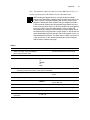
Modified Menu Tree
The parameters and functions accessed via the MENU/ESC key are organized in
a tree-like structure, or a “menu”, shown in Figure 8. The menu operations related
to the E & M console are emphasized, while the standard DIU operations (covered
in the DIU3000 Owner's manual) are shaded.
Operation
15
.
READY STATE
(TIME OF DAY DISPLAY)
ACTIVITY
BASE
INBOUND
DBM
E AND M
MRTI
USER
CONSOLE
SLNT
AGC
AUTO
CLOCKSET
CONSOLE
ID
MRTI
ID
E AND M
EDITPSWD
DBM
SLNT
AGC
AUTO
DBM
ID
DBM
MAINT
USER
ID
MICSNS
TIME FMT
LIGHT
CONTRS
MAINT
USER
CRYPTO
MAINT
USER
CRYPTO
AGC
SLNT
AUTO
CRYPTO
ERR LIST
HANDSET
LCD
LOGIN
LOGOUT
SERVICE
TESTS
TX PARAMS
OTAR
LOGIN
LOGOUT
AUD LOOP
ACCS
RKEY REQ
LEGEND
Use arrows [^]/[|]
Use [ENTR] key
Figure 8
E & M Console Related Menu Operations
16
E&M Console Interface Owner’s Manual
Activity
This menu provides a means of monitoring transmit/receive parameters of the
DIU and control devices connected to it.
– For the E AND M (E & M Console), the CHaNneL and MODE parameters of
the current transmission can be traced. If not currently transmitting, the last
active parameters are displayed.
Table 4
Action
LCD Display
1. While in the ready mode, press MENU/
ESC to enter the menu mode.
The last accessed menu entry is shown.
2. Scroll until ACTIVITY is shown.
ACTIVITY
3. Press ENTR to enter the device selection
menu.
CONSOLE
or
INBOUND
or
E AND M
or
MRTI
or
USER
4. Scroll to display the required device
option.
5. Press ENTR to display activity
parameters that can be traced for the
selected device.
Comments
E AND M
CHNL nnn
or
ANALOG/
CLEAR/
ENCR nnn
•
•
The data displayed is updated once a
second, or if ENTR is pressed.
If there was no inbound process since
power–up and ENTR is pressed while in
INBOUND ACTIVITY display state, the
message NO INFO is displayed.
6. Use the arrow keys to scroll between the
available parameters.
7. Press MENU/ESC to return to the ready
state.
E and M
This menu controls the parameters of the communication interface to the E & M
Console. The following parameters can be changed:
.
Changing the E & M console interface parameters requires entering
the service password.
Note
– Line signal level. The line signal level can be set within the range of –20 to
0 dBm.
– ID. Enables viewing the E & M Console ID, shown in decimal format.
Operation
.
17
Changing the line signal level requires entering the service password.
Note
.
Table 5
Action
LCD Display
1. While in the ready mode, press MENU/
ESC to enter the menu mode.
Comments
The last accessed menu entry is shown.
2. Scroll until E AND M is shown.
E AND M
3. Press ENTR to display the options.
DBM nn
or
ID HHH
4. Scroll to display the required option.
ID HHH shows the console ID in hexadecimal
format
If changing/viewing of line signal level is not required, skip to step 9.
5. Scroll to select the DBM option.
DBM nn
“nn” indicates the currently selected signal
level in dBm units.
6. Press ENTR.
DBM nn
“nn” blinks.
7. Scroll to select the required value.
DBM mm
“mm” indicates the new selected signal level.
8. Press ENTR to confirm the selection.
DBM mm
9. Press MENU/ESC twice to return to the
ready state.
8 : 46 : 16
18
E&M Console Interface Owner’s Manual
Troubleshooting
In case of DIU malfunctioning when the E & M Console is used, first perform the
troubleshooting procedures given in the TROUBLESHOOTING chapter of the
DIU3000 Owner’s manual 68P02949C65. If the DIU is found operational, follow
the E & M Console function troubleshooting chart given below.
.
E & M CONSOLE AUDIO NOT
HEARD BY SUBSCRIBER
IS THE
TX LED ON WHEN
PTT IS
PRESSED?
NO
CHECK THE DIU TO E & M
CONSOLE CONNECTION
(PTT LINE)
NO
CHECK THE DIU TO E & M
CONSOLE CONNECTION
(SELECT LINES)
YES
DOES THE DIU
“ACTIVITY: E AND M”
FUNCTION DISPLAY THE
SAME MODE AS SET BY
THE RSS?
YES
CHECK THE DIU TO E & M
CONSOLE CONNECTION
(AUDIO LINE)
Figure 9
Troubleshooting Chart
Appendix A: Connectors and Cables
Appendix A: Connectors and Cables
Table 6
OPT. 1 (General Purpose I/O) Connector Pin Description
Pin
No.
Description
I/O Type
Logic Low =
Junction Box
Corresponding
Pin No.*
(option C62AB)
1
Receiver Unsquelch to Centracom console
logic output†
Unsquelch‡
TB4–2
2
Not used
3
Not used
4
Digital ground
5
MONITOR
logic input
Unsquelch‡
TB4–4
6
PTT from E & M Console
logic input
PTT active‡
TB3–1
7
M_LEAD (PTT output)
logic output†
PTT active
TB2–1
8
Input_1 (SEL_1)
logic input
TB3–2
9
Input_2 (SEL_2)
logic input
TB3–7
10
Not used
11
Not used
12
External speaker
analog output
TB5–5
13
External battery (+)
power input
TB5–6
14
Not used
15
Not used
16
Not used
17
Not used
18
Not used
19
Analog ground
20
Not used
21
Mode indication to Centracom
22
Not used
23
Not used
24
External speaker ground
25
External battery (–)
TB4–3
TB1–2
logic output†
Mode 1‡
TB4–1
TB5–8
power return
TB5–7
*.When using the Junction Box connect TB4–7 and 8 to good earth ground to ensure surge protection.
†.Internally pulled up to 15 Vdc by a 10 K9 resistor.
‡.Polarity can be reversed (to active high) using RSS.
19
20
E&M Console Interface Owner’s Manual
Appendix B: Acronyms
DIU
Digital Interface Unit
DTMF
Dual Tone Multi-Frequency (signal)
EMC
Encryption Module Cartridge
E&M
Ear and Mouth
FDX
Full Duplex
FREQ
Function Request
HDX
Half Duplex
RSS
Radio Service Software