1
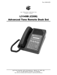
Pub. 43004-007C GAI-TRONICS® CORPORATION A HUBBELL COMPANY ILD1000A Local Desk Set User and Installation Manual GAI-Tronics Corporation 400 E. Wyomissing Ave. Mohnton, PA 19540 USA 610-777-1374 800-492-1212 Fax: 610-796-5954 VISIT WWW .GAI-TRONICS.COM FOR PRODUCT LITERATURE AND MANUALS CONFIDENTIALITY NOTICE This manual is provided solely as an operational, installation, and maintenance guide and contains sensitive business and technical information that is confidential and proprietary to GAI-Tronics. GAI-Tronics retains all intellectual property and other rights in or to the information contained herein, and such information may only be used in connection with the operation of your GAI-Tronics product or system. This manual may not be disclosed in any form, in whole or in part, directly or indirectly, to any third party. COMPUTER SOFTWARE COPYRIGHTS This product contains copyrighted computer programs stored in semiconductor memory. These programs are copyrighted by GAI-Tronics Corporation and may not be reproduced in any form without express written permission from GAI-Tronics. WARRANTY GAI-Tronics warrants for a period of one (1) year from the date of shipment, that any GAI-Tronics equipment supplied hereunder shall be free of defects in material and workmanship, shall comply with the then-current product specifications and product literature, and if applicable, shall be fit for the purpose specified in the agreed-upon quotation or proposal document. If (a) Seller’s goods prove to be defective in workmanship and/or material under normal and proper usage, or unfit for the purpose specified and agreed upon, and (b) Buyer’s claim is made within the warranty period set forth above, Buyer may return such goods to GAI-Tronics’ nearest depot repair facility, freight prepaid, at which time they will be repaired or replaced, at Seller’s option, without charge to Buyer. Repair or replacement shall be Buyer’s sole and exclusive remedy, and the warranty period on any repaired or replacement equipment shall be one (1) year from the date the original equipment was shipped. In no event shall GAI-Tronics’ warranty obligations with respect to equipment exceed 100% of the total cost of the equipment supplied hereunder. The applicability of any such third-party warranty will be determined solely by GAI-Tronics. Services. Any services GAI-Tronics provides hereunder, whether directly or through subcontractors, shall be performed in accordance with the standard of care with which such services are normally provided in the industry. If the services fail to meet the applicable industry standard, GAI-Tronics will, for a period of one (1) year from the date of completion, re-perform such services at no cost to the Buyer. Re-performance of services shall be Buyer’s sole and exclusive remedy, and in no event shall GAI-Tronics’ warranty obligations with respect to services exceed 100% of the total cost of services provided hereunder. Limitations/Exclusions. The warranty on any equipment supplied hereunder is subject to Customer’s use in compliance with applicable FCC regulations and manufacturer specifications. The warranties herein shall not apply to, and GAI-Tronics shall not be responsible for, any damage to the goods or failure of the services supplied hereunder, to the extent caused by accident, misuse, abuse, neglect, system design, product modification, failure to follow instructions contained in the product manual, repair, or attempted repair by anyone not authorized by GAI-Tronics, improper installation, installation of parts that do not conform to the quality or specifications of the original parts or accessories, damage or loss occurred during shipment, or any unit which is not new when sold or upon which the serial number has been defaced, modified or removed. The warranty does not extend to damage incurred by natural causes including Force Majeure. The warranty does not cover microprocessors if failure is due to static damage or application of improper voltage. THE WARRANTIES AND REMEDIES CONTAINED HEREIN ARE IN LIEU OF AND EXCLUDE ALL OTHER WARRANTIES AND REMEDIES, WHETHER EXPRESS OR IMPLIED BY OPERATION OF LAW OR OTHERWISE, INCLUDING ANY WARRANTIES OF MERCHANTABILITY OR FITNESS FOR A PARTICULAR PURPOSE. Operational and Maintenance Procedures. Buyer acknowledges that any improper use, maintenance, or modification of the equipment provided hereunder, or use of unqualified maintenance or service technicians will severely impair the operational effectiveness of the entire communication system. Buyer hereby agrees to indemnify, defend and hold GAITronics harmless from and against any and all third party claims arising, in any manner, out of: (a) Buyer’s neglect of the equipment; (b) Buyer’s use of technicians not authorized by GAI-Tronics to service the equipment; or (c) Buyer’s improper use or modification of the equipment or failure to follow the operational and maintenance procedures provided with the equipment. Limitation of Liability/Damages. In no event (even should circumstances cause the exclusive warranties and remedies set forth in the Warranty section to fail of their essential purpose) shall either party be liable for any indirect, incidental, special or consequential damages (including, but not limited to, loss of use, loss of anticipated profits, or damages arising from delay) whether such claims are alleged to have arisen out of breach of warranty, breach of contract, strict or absolute liability in tort, or other act, error or omission, or from any other cause whatsoever, or any combination of the foregoing. 02/12 Publication 43004-007C i Table of Contents FOREWORD ............................................................................................................................................................... 1 SCOPE OF MANUAL .................................................................................................................................................... 1 NOMENCLATURE ........................................................................................................................................................ 1 ORDERING REPLACEMENT PARTS .............................................................................................................................. 1 SERVICE AND REPAIR ................................................................................................................................................. 1 FEATURES AND BENEFITS OF THE ILD1000A LOCAL DESK SET ................................................................................ 2 FCC INTERFERENCE WARNING .................................................................................................................................. 2 SAFE HANDLING OF CMOS INTEGRATED CIRCUIT DEVICES ...................................................................................... 3 PERFORMANCE SPECIFICATIONS ................................................................................................................................. 4 DESCRIPTION............................................................................................................................................................ 5 PHYSICAL DESCRIPTION ............................................................................................................................................. 5 DESK SET BUTTON PANEL ......................................................................................................................................... 5 Volume Buttons ..................................................................................................................................................... 5 CTL (Control) Button ............................................................................................................................................ 5 IC (Intercom) Button ............................................................................................................................................. 5 Monitor Button...................................................................................................................................................... 5 Transmit Button and LED ..................................................................................................................................... 5 INTERNAL MICROPHONE ............................................................................................................................................ 5 HANDSET ................................................................................................................................................................... 6 PERSONALITY PROGRAMMING SWITCH (SWA) .......................................................................................................... 6 SWA Switch Settings Table ................................................................................................................................... 6 ILD1000A BASIC LOCAL DESK SET FIELD REPLACEMENT ITEMS.............................................................................. 6 OPERATION ............................................................................................................................................................... 7 FRONT PANEL BUTTON OPERATION ........................................................................................................................... 7 VOLUME Up/Down Buttons................................................................................................................................. 7 (CTL) Control Button ............................................................................................................................................ 7 IC (Intercom) Button ............................................................................................................................................. 7 MONITOR Button ................................................................................................................................................. 7 TRANSMIT Button ................................................................................................................................................ 7 RECEIVING CALLS ...................................................................................................................................................... 7 Local Speaker ....................................................................................................................................................... 7 INITIATING CALLS ...................................................................................................................................................... 8 HANDSET TRANSMIT .................................................................................................................................................. 8 TRANSMIT FROM INTERNAL MICROPHONE................................................................................................................. 8 FULL DUPLEX OPERATION ......................................................................................................................................... 8 INSTALLATION ......................................................................................................................................................... 9 PLANNING THE INSTALLATION.................................................................................................................................... 9 MECHANICAL RECEIPT INSPECTION ........................................................................................................................... 9 MOUNTING ................................................................................................................................................................. 9 FCC INTERFERENCE WARNINGS ................................................................................................................................ 9 EQUIPMENT REQUIRED ............................................................................................................................................. 10 Test Equipment ................................................................................................................................................... 10 Documentation .................................................................................................................................................... 10 02/12 Publication 43004-007C ii Table of Contents ILD1000A Local Desk Set CABLE INSTALLATION SAFETY CONSIDERATIONS..................................................................................................... 10 ELECTROSTATIC DISCHARGE (ESD) PROTECTION .................................................................................................... 10 CONNECTIONS .......................................................................................................................................................... 11 POWER CONNECTION ............................................................................................................................................... 11 RADIO CONNECTION ................................................................................................................................................ 11 Terminal Strip Table ........................................................................................................................................... 12 Local Desk Set to MCS 2000 Radio Connection Chart ...................................................................................... 12 Local Desk Set to RPG Radio Connection Chart................................................................................................ 13 SETTINGS AND ADJUSTMENTS .................................................................................................................................. 13 Transmit Level Adjustment.................................................................................................................................. 13 Line (Receive Audio) Input Level Adjustment ..................................................................................................... 14 Intercom Audio Input Adjustment ....................................................................................................................... 14 Handset Microphone........................................................................................................................................... 14 DESK SET REASSEMBLY ........................................................................................................................................... 14 THEORY OF OPERATION .................................................................................................................................... 15 DIGITAL CIRCUITS .................................................................................................................................................... 15 AUDIO CIRCUITS ...................................................................................................................................................... 15 SPEAKER VOLUME CONTROL ................................................................................................................................... 16 POWER SUPPLIES ...................................................................................................................................................... 16 TROUBLESHOOTING ............................................................................................................................................ 17 TROUBLESHOOTING THE ILD1000A BASIC LOCAL DESK SET.................................................................................. 17 FUSE REPLACEMENT ................................................................................................................................................ 18 MAIN CIRCUIT BOARD ........................................................................................................................................ 19 SCHEMATICS .......................................................................................................................................................... 21 DEFINITIONS AND ACRONYMS ......................................................................................................................... 27 02/12 Publication 43004-007C iii Foreword Scope of Manual This manual offers descriptive data and service information for the ILD1000A Local Desk Set. Service diagrams and printed circuit board details are a part of this service manual. Nomenclature The model number, located on the nameplate on the bottom, specifically identifies GAI-Tronics equipment. If additional options are ordered, the option will be identified on the circuit board. Ordering Replacement Parts When ordering replacement parts or requesting equipment information, please include the complete identification number. This applies to all components, kits, and chassis. If the component part number is not known, the order should include the number of the chassis or kit of which it is a part and sufficient description of the desired component to identify it. Order parts from: Customer Service GAI-Tronics Corporation 400 E. Wyomissing Ave. Mohnton, PA 19540 US: 800-492-1212 Outside US: 610-777-1374 Service and Repair Inoperative or malfunctioning equipment should be returned to the factory for repair. Please call 1-800-492-1212 to obtain a Return Authorization number, published repair prices, and shipping instructions. NOTE: A purchase order or credit card number is required prior to processing non-warranty repairs. 1 02/12 Foreword ILD1000A Local Desk Set Features and Benefits of the ILD1000A Local Desk Set Feature Benefit Selectable latching monitor User can select the monitor function to continue after the MONITOR button has been released. Intercom Desk set users can communicate with each other without tying up valuable air time. Multiple parallel desk set support Enhanced productivity and system flexibility by connecting several desk sets to a single radio via a junction box. Selectable parallel transmit audio mute Prevents feedback between desk sets in close proximity during transmit. Selectable off-hook monitor User can choose automatic monitor when handset is picked up. Selectable local speaker User can turn on the local speaker when the handset is picked up. Front panel audio mute/unmute Allows user to mute receive audio ‘on-the-fly.’ Adjustable receive input and transmit output level Allows flexibility with different radio systems and user environments, where radio output levels, line losses, and noise factors vary. Full-duplex capable Useful for full-duplex and trunking radio systems with talk and listen only. See page 8 for a description of full duplex operation. Built-in microphone and speaker Allows for handset-free communication. FCC Interference Warning The FCC requires that manuals pertaining to Class A and Class B computing devices must contain warnings about possible interference with local residential radio and TV reception. This warning reads as follows: NOTE: This equipment has been tested and found to comply with the limits for a Class A digital device, pursuant to Part 15 of the FCC Rules. These limits are designed to provide reasonable protection against harmful interference when the equipment is operated in a commercial environment. This equipment generates, uses, and can radiate radio frequency energy and, if not installed and used in accordance with the instruction manual, may cause harmful interference to radio communications. Operation of this equipment in a residential area is likely to cause harmful interference in which case the user will be required to correct the interference at his own expense. 02/12 2 ILD1000A Local Desk Set Foreword Safe Handling of CMOS Integrated Circuit Devices Many of the integrated circuit devices used in communications equipment are of the Complementary Metal Oxide Semiconductor (CMOS) type. Because of their high open circuit impedance, CMOS integrated circuits are vulnerable to damage from static charges. Care must be taken handling, shipping, and servicing them and the assemblies in which they are used. Even though protection devices are provided in CMOS integrated circuit inputs, the protection is effective only against overvoltage in the hundreds of volts range such as is encountered in an operating system. In a system, circuit elements distribute static charges and load the CMOS circuits, decreasing the chance of damage. However, CMOS circuits can be damaged by improper handling of the modules, even in a system. To avoid damage to circuits, observe the following handling, shipping, and servicing precautions: 1. Prior to and while servicing a circuit module, particularly after moving within the service area, momentarily touch both hands to a bare metal, earth-grounded surface. This will discharge any static charge which may have accumulated on the person doing the servicing. NOTE: Wearing a conductive wrist strap will minimize static build-up during servicing. 2. Whenever possible, avoid touching any electrically conductive parts of the circuit module with your hands. 3. Power down the unit before installing or removing the circuit module. 4. When servicing a circuit module, avoid carpeted areas, dry environments, and certain types of clothing (silk, nylon, etc.) because they contribute to static build-up. Similarly, disconnect the test probe prior to removing the ground lead. 5. All electrically powered test equipment should be grounded. Apply the ground lead from the test equipment to the circuit module before connecting the test probe. 6. If a circuit module is removed from the system, it is desirable to lay it on a conductive surface (such as a sheet of aluminum foil) which is connected to ground through 100k of resistance. 7. When soldering, be sure the soldering iron is grounded, and has a grounded tip. 8. Prior to connecting jumpers, replacing circuit components, or touching CMOS pins (if this becomes necessary in the replacement of an integrated circuit device), be sure to discharge any static build-up as described in procedure 1. Since voltage differences can exist across the human body, it is recommended that only one hand be used if it is necessary to touch pins on the CMOS device and associated board wiring. 9. When replacing a CMOS integrated circuit device, leave the device in its conductive rail container or conductive foam until it is to be inserted into the printed circuit module. 10. All low impedance test equipment (such as pulse generators, etc.) should be connected to CMOS device inputs after power is applied to the CMOS circuitry. Similarly, such low impedance equipment should be disconnected before power is turned off. 11. Replacement modules shipped separately from the factory will be packaged in a conductive material. Any modules being transported from one area to another should be wrapped in a similar material (aluminum foil may be used). Never use non-conductive material for packaging these modules. 3 02/12 Foreword ILD1000A Local Desk Set Performance Specifications Color ..................................................................................................................................................... Black Physical Size ................................................................................................... 7.6 W 6.3 L 4.7 H inches Weight ................................................................................................................................................... 4 lbs. Temperature range .............................................................................................................. −35º C to +70º C Humidity ...................................................................................................... 95% at 50º C (non-condensing) Power input ............................................................................................. 10.5–16 V dc - 400 mA maximum Frequency response................................................................ +/−3 dB, 300–3000 Hz from 1 kHz reference Hum and noise ................................................................................ Better than −45 dB below rated outputs Audio output to speaker ................................................................. 1 watt minimum with reference to input Audio distortion .............................................................................................................. Less than 3% THD Receive audio level ......................................................................................................... 200 mVRMS–4 VRMS Transmit audio level ...................................................................................... 50–250 mVRMS into 560 ohms Maximum number of parallel desk sets ................................................................................................... Ten Control Functions: Monitor ......................................................................................................................................... Active low Transmit ........................................................................................................................................ Active low 02/12 4 Description Physical Description The ILD1000A is an extended local control desk set. Up to ten desk sets can be connected in parallel, allowing up to ten dispatch points for one radio system. The ILD1000A operation can be customized using DIP switches 1, 2, and 3. Refer to the switch settings table later in this section for more information. Desk Set Button Panel Refer to the figure below for the locations of the buttons and LEDs on the desk set button panel. Volume Buttons The desk set includes two buttons imprinted with up and down arrows and labeled VOLUME. They are used to increase and decrease the local speaker volume and as programming function keys. GAI-TRONICS ILD1000 CTL (Control) Button The CTL button is used in conjunction with the VOLUME Up or VOLUME Down buttons to control the local speaker. VOLUME CTL IC (Intercom) Button IC MONITOR The IC button allows communication between desk set users without transmission over the radio. TRANSMIT Monitor Button The MONITOR button is used to place the radio in the monitor mode. Figure 1. Front View of the ILD1000A Desk Set Button Panel Transmit Button and LED The TRANSMIT button is used to initiate voice transmissions. Pressing the TRANSMIT button places the desk set in the transmit mode. The TRANSMIT LED illuminates when transmitting. Internal Microphone This microphone is intended for use in low noise environments. The handset must be on-hook in order to use the microphone. 5 02/12 Description ILD1000A Local Desk Set Handset The desk set is equipped with a handset with a coil cord used for receiving and transmitting calls. The handset includes a push-to-talk (PTT) pressbar. Personality Programming Switch (SWA) Refer to the Main Circuit Board diagram at the end of this manual for the location of the Personality Programming SWA switch. SWA Switch Settings Table Switch Determines: On Off (default) SWA-1 Automatic Off-hook Monitor Monitor is asserted when handset is taken off-hook. Disabled SWA-2 Latching MONITOR button. Monitor output latches after MONITOR press (until PTT occurs.) Monitor output activated only for duration of button press. SWA-3 Parallel audio mute operation. Mutes speaker audio while parallel desk set is transmitting. Handset is not muted. TX audio from parallel desk set is heard in speaker. SWA-4 Not used. N/A N/A SWA-5 Not used. N/A N/A SWA-6 Not used. N/A N/A SWA-7 Not used. N/A N/A SWA-8 RX audio level. 1–4 VRMS 200 mVRMS–1 VRMS After any switch setting changes (except SWA-8), the power to the desk set must be cycled for the new settings to take effect. ILD1000A Basic Local Desk Set Field Replacement Items Description Part No. Fuse, Bussmann Type GMA 750 mA FB 4612-23570-00 Handset, Black HANDSET-BLACK PCBA, Replacement “LTL” 69294-003 Speaker Assembly 61501-014 02/12 6 Operation Front Panel Button Operation VOLUME Up/Down Buttons Press the VOLUME Up or VOLUME Down buttons to adjust the local speaker volume. They are also used as programming function keys. (CTL) Control Button The CTL button is used in conjunction with the VOLUME Up and Down buttons to manually control the local speaker. Press and hold the CTL button, and then press the VOLUME Up or VOLUME Down button. IC (Intercom) Button Press the IC button to communicate between desk sets without transmitting over the radio. When the IC button is pressed and held, microphone audio is routed to the line without activating the radio transmitter. Other parallel desk sets will hear the audio automatically. MONITOR Button Press the MONITOR button (CTCSS/CDCSS disable) to place the radio in the monitor mode. Press this button before making a call to verify a clear radio channel is available. TRANSMIT Button Press the TRANSMIT button to place the desk set in the transmit mode and initiate voice transmissions. With the handset on-hook, transmit audio is picked up from the internal microphone. Receiving Calls Local Speaker When power is applied, the desk set is in the receive mode, allowing receive audio to be heard through the speaker or handset. The desk set is always in receive mode unless the user presses the TRANSMIT or IC buttons. The desk set contains an internal (local) speaker and a handset speaker, which operate as follows: When the handset is in the cradle, or on-hook, receive audio is heard on the local speaker. When the handset is off-hook, receive audio is routed to the handset. Muting the Local Speaker: Press CTL + VOLUME Down to mute the local speaker. The selected frequency button flashes to indicate that the speaker is muted. Unmute the speaker by pressing VOLUME Up, VOLUME Down, or CTL + VOLUME Up. Press CTL + VOLUME Up to enable the local speaker while the handset is off-hook. When the handset is placed back on-hook, the local speaker again operates normally– that is, it will be disabled whenever the handset is taken off-hook. 7 02/12 Operation ILD1000A Local Desk Set Initiating Calls Before initiating a call, press the MONITOR button to verify that the radio channel is clear. To initiate a call, press the TRANSMIT button or the handset push-to-talk (PTT) pressbar. The TRANSMIT LED illuminates when transmitting. Always allow a short delay before speaking to allow time for the radio channel to be established. The TRANSMIT button or handset PTT bar must be held down while talking to the radio user and released to listen. When the transmission is completed, the TRANSMIT LED extinguishes and the desk set returns to the receive mode. Handset Transmit Using the handset is recommended when the desk set is located in noisy surroundings. Press the handset PTT bar or TRANSMIT button and speak into the handset microphone. Transmit From Internal Microphone Use the internal microphone only in low noise environments. The handset must be on-hook for the internal microphone to operate. Press the TRANSMIT button and speak in the direction of the internal microphone. For the best transmit audio quality, maintain a distance of about 12 to 18 inches from the microphone. Full Duplex Operation For full duplex operation (TX and RX simultaneously) the handset must be used to speak to the mobile user while pressing the ILD1000A TRANSMIT button. 02/12 8 Installation Planning the Installation Figure 2. Sample ILD1000A Desk Set Installation Diagram Shown connected in parallel within one building. NOTE: Maximum distance from the radio is limited to 1000 feet of total cable length. Mechanical Receipt Inspection The ILD1000A Local Desk Set is shipped in a cardboard container with inserts. Thoroughly inspect it as soon as possible after delivery. In-transit damage should be immediately reported to the transportation company. Mounting The ILD1000A Desk Set can be placed on a desk or mounted vertically on a wall. To wall mount the desk set, remove the four bottom screws from the base and then rotate the base 180. Reinstall the four screws to the base and rotate the handset hook located on the front of the unit. FCC Interference Warnings The FCC requires that manuals pertaining to Class A and Class B computing devices contain warnings about possible interference with local and residential radio and TV reception. Please read these warnings and all safety information in the Foreword section of this manual. 9 02/12 Installation ILD1000A Local Desk Set Equipment Required Test Equipment High-impedance type audio voltmeter with a range of 80 mVRMS to 4 VRMS capable of measuring 1000 Hz #1 Phillips screwdriver 1/8-inch flat-blade screwdriver Optional: RF service monitor Documentation Radio schematics Radio manual Installation instructions Cable Installation Safety Considerations Wiring should conform to the Article 800 of the National Electrical Code. Use listed communication wiring and cabling for interconnection to other equipment that is suitable for the purpose. Cables should be marked as CM, CMP, CMR, or CMX as appropriate for the use. Interconnecting data cables should be separated from electrical light or other Class I power cables by at least 2 inches. The exception is where Class I wiring or power circuits are run in a raceway, or are metal-sheathed or metal-clad, or are permanently separated from the conductors of the other circuitry by a continuous and firmly fixed nonconductor, such as porcelain tubes or flexible tubing in addition to the insulation on the wire. Interconnecting cables longer than 2 meters should be rated VW-1 or FT-1 or greater. The recommended cable kits conform to these requirements. Electrostatic Discharge (ESD) Protection This equipment has ESD protection circuitry which provides a high degree of protection against ESD and power and telephone line surges. The circuitry shunts the transient currents to earth ground through the GND terminal. Terminal 8 inside the desk set on the TS1 terminal block can be used as an earth GND terminal. The GND terminal must be connected to a high quality earth ground point to obtain maximum protection. Ideally, the ground point should originate at a 1/2-inch copper rod driven at least 6 feet into the soil with a No. 16 AWG (or larger) copper wire run to the GND terminal taking the shortest path possible. Where this is not possible, ground to a nearby water pipe or best available ground. 02/12 10 ILD1000A Local Desk Set Installation Connections Cable length limitations are imposed by power losses in the cable and stray noise pickup on the microphone line. Cable length should be less than 1000 feet to maintain satisfactory performance. To make the required line connections, a cable with tinned bare leads stripped to about 1/4 inch (6 mm) is necessary. All interface connections are made inside the unit. To open the housing, remove the four screws in the corners on the back housing and lift off the top cover. Desk sets powered by a wall transformer or base station power supply can be connected in parallel on a single cable. Refer to the radio manual and schematics to locate connection points. If they can not be located, contact the manufacturer's technical support group. Multiple cable tie points are not provided. Power Connection Make the power connection to a 12 V dc source capable of supplying up to 0.5 A per desk set. This may be obtained from a direct connection to the radio power supply. NOTE: Do not obtain power for the desk set from the radio accessory connector. Damage to the radio may result. As an option, power can be supplied to the ILD1000A Desk Set from a listed Class 2 120 V ac wall adapter. (The desk set is rated as Class III SELV powered equipment). The ac adapter is necessary if: more than one unit is connected to a single base station, or if the desk set is used more than 300 feet from the base station. The desk set can operate on dc input voltages from 10.5 to 16 volts. Connect the power supply as follows: Positive (white striped) lead to Terminal Strip 1, terminal 1 Negative (black) lead to Terminal Strip 1, terminal 8 Radio Connection All power and radio interface connections are made to the eight-position terminal strip on the main circuit board. The desk set must be opened for access to this terminal strip. 1. Route the cable through the slot on the bottom rear corner of the desk set housing. 2. Loosen the eight slotted screws on the terminal strip and insert the cable wires into position according to the terminal strip table below. 3. After connections to the radio cable and dc supply have been made, verify the positions to ensure they are correct. 4. Apply power. Press the PTT pressbar on the handset to test the transmit function and the MONITOR button to test the receive function. 11 02/12 Installation ILD1000A Local Desk Set Terminal Strip Table TS1 Terminal Wire Color Function 1 Red The dc power positive (+) input 2 Orange RX audio 3 Yellow RX audio return 4 Shield TX audio return 5 Brown TX audio 6 White Monitor output (active low) 7 Green PTT output (active low) 8 Black The dc power negative (–) and surge/logic ground NOTE: RX and TX audio return (from all desk sets) must be connected to ground (or return) at the base station and NOT grounded at the desk set(s). Local Desk Set to MCS 2000 Radio Connection Chart TS1 Pin # Desk Set Function Wire Color Radio Connector Pin # 1 DC+ power input Red 14 Switched B+ when radio is on 2 RX audio + Orange 11 RX audio 3 RX audio – Yellow 10 Ground 4 TX audio – Shield 10 Ground 5 TX audio + Brown 13 TX audio 6 monitor White 7 monitor 7 PTT Green 21 PTT 8 DC– power ground Black 10 Ground Radio Function NOTE: All common ground connections should be made at the radio to prevent ground loops. Figure 3. HLN6412 Connector Termination with Internal Jumpers Connecting Pins 1–2 and Pins 4–9. 02/12 12 ILD1000A Local Desk Set Installation Local Desk Set to RPG Radio Connection Chart TS1 Pin # Desk Set Function Wire Color Radio Connector Pin # 1 DC+ power input Red 13 Switched B+ when radio is on 2 RX audio + Orange 11 RX audio 3 RX audio – Yellow 7 Ground 4 TX audio – Shield 7 Ground 5 TX audio + Brown 2 TX audio 6 Monitor White 14 Monitor 7 PTT Green 3 PTT 8 DC– power ground Black 7 Ground Radio Function NOTE: 1. The radio must be programmed to disable emergency functions from pin 9. 2. All common ground connections should be made at the radio to prevent ground loops. Figure 4. Settings and Adjustments The desk set housing must be open with the circuit board exposed. These procedures assume that the base station has been properly adjusted. Transmit Level Adjustment This level is factory set to provide 80 mVRMS into a 560 ohm load, which is adequate for many applications. If adjustment is needed, perform the following steps: 1. Monitor the station transmitter with an RF service monitor or communications system analyzer. 2. Talk into the handset and adjust the level of the TX audio level pot 4 on the main circuit board for an approximate 60% average level with peaks of 100% modulation. 3. If a service monitor is not available, use the ac voltmeter to monitor the transmit level at the terminal strip screw terminals 4 (−) and 5 (+) for the audio level required by the radio station. Refer to the radio manual for the audio level specifications. 13 02/12 Installation ILD1000A Local Desk Set Line (Receive Audio) Input Level Adjustment The desk set can adapt to input levels ranging from 200 mVRMS to 4.0 VRMS using the appropriate DIP switch setting. The DIP switch is located on the main printed circuit board. The RX sensitivity has been factory set to receive 300 mV ac. 1. Set the range by placing SWA-8 to where it most closely matches the available receive audio level. Refer to the SWA Switch Settings Table on page 6. 2. Apply an RF generator modulated by a 1 kHz tone at reference modulation level to the station receiver and adjust pot 1 on the main circuit board for a measured level of 800 mVRMS at the TREF test point. 3. If an RF generator is not available, use an audio oscillator to apply a 1 kHz tone to the receive audio line at the nominal level expected from the radio. 4. Adjust the RX audio level pot 1 for a measured level of 800 mVRMS at the TREF test point. Intercom Audio Input Adjustment This audio level is factory set to provide the reference volume with a transmit/intercom audio level of 80 mV ac. If adjustments are needed: 1. Apply a steady 1 kHz tone to the transmit pair from a parallel desk set or audio generator connected to terminal screws TS1-4 and TS1-5 with the output level set to the radio's recommended transmit audio level. 2. Measure the level at the TREF test point. Adjust the parallel audio level pot 2 to provide 800 mVRMS at the TREF test point. Handset Microphone This adjustment is factory-set at a nominal level suitable for many applications. Make adjustments only after the receive audio level pot and SWA-8 have been properly set. 1. Locate the handset earpiece volume control which is accessible through the lower slotted mounting hole (pot 3) without opening the unit. 2. If adjustment is needed, use a 1/8-inch slotted screwdriver to adjust pot 3 to a comfortable volume level. Desk Set Reassembly 1. After making the required connections, replace the top cover on the desk set and reattach the four screws in each corner of the bottom housing. 2. To wall mount, affix the desk set to the wall using the molded-in mounting holes. 02/12 14 Theory of Operation Digital Circuits On power-up, microcontroller U1 reads switch SWA through tri-state buffer U2. Switch readings determine operating characteristics of the desk set. Periodically, U1 reads the state of keyboard buttons via its bidirectional I/O ports. Monitor is asserted by the microcontroller through Q10 and associated components. The circuit consisting of Q11, U3e, and associated components provides indication that the monitor function is asserted (whether by this desk set or a parallel-connected device). This indication is used to light the MONITOR LED through U3d and Q2. PTT is asserted by the microcontroller through Q12 and associated components. The circuit consisting of Q13, U3f, and associated components provides indication that the PTT function is asserted (whether by this desk set or a parallel-connected device). This indication is used to light the TRANSMIT LED through U3c and Q1. Also, this indication is input to the microcontroller to allow tracking the status of parallel units. Comparator U4a outputs a logic “low” when the handset is taken off-hook. This logic signal selects either the handset or internal microphone, and it is input to the microcontroller where it is examined it to determine proper speaker handling. Comparator U4b outputs a logic “high” when the handset PTT bar is depressed. This signal is ORed with the TRANSMIT button to allow it to be read by the microcontroller. Audio Circuits Audio from the internal microphone or handset microphone is amplified by U12b and scaled to the required level by U12a. POT4 is adjusted during installation to ensure that the level presented to the TX audio port is correct for the associated radio. Whenever PTT is asserted or the Intercom button is pressed, the circuit consisting of U15b, Q5, Q6, and Q7 gates microphone audio to the radio’s TX audio port. Radio receiver audio is input through differential amplifier U10d. Intercom and transmit audio from parallel units is input through differential amplifier U10c. During installation, POT1 and POT2 are adjusted to ensure that the internal intercom and receive audio levels at test point TREF are approximately 800mVRMS. Summed receiver and intercom audio is scaled through U10a and fed to power amplifier U17. It is also gated through U15a to the handset earpiece. POT3 adjusts the handset earpiece volume. The handset earpiece is automatically disabled through Q4 whenever the handset PTT bar or Intercom button is pressed. 15 02/12 Theory of Operation ILD1000A Local Desk Set Speaker Volume Control The actual speaker output level adjustment is done internally within power amp U17. The control circuit for this provides a precise control current sink connected to pin 5 of U17. The microcontroller examines the VOLUME Up/Down button presses and provides control pulses to electronic pot U16. U16 provides a variable reference voltage into the divider resistors connected to U11 pin 10. Speaker muting voltage is also connected to this divider through R105. U11c is connected with Q3 as a programmable current sink for U17 output gain adjustment. A voltage higher than 60 millivolts dc at Q3 source (and R110) results in muting the speaker. Less than 1 millivolt dc results in full output. Power Supplies The power supplies for the low tier desk set operate in the linear series-pass mode. Programmable zener U21 serves as reference for the 5 V digital and analog power supplies. The reference voltage is 5.00 V dc, +/−0.1 V dc measured at U21-1. Op-amp U13b controls the series pass element Q21 to provide 5 V dc at the 5 VD source point at C55, C56. The 5 VA supply is low-current and is fully implemented by U13a. The VOS power supply, used to power the op-amp rails, is regulated to be approximately 11.2 volts. The voltage level of the VOS supply is approximately 1.2 volts above the 10 V (nominal) CMOS switch power supply. The reference for VOS is the 5 VD output. The divided output sample (through R133, R134, Q24 and R135) is compared to the reference at Q23, which serves as the control element for the series pass transistor Q22. 02/12 16 Troubleshooting Troubleshooting the ILD1000A Basic Local Desk Set The following is a list of potential problems you may encounter and possible solutions. Problem Possible Solution The desk set will not key the station transmitter. Check cable wiring to radio and desk set terminals Ensure that the collector-emitter junction of Q12 is not open. The radio is keyed constantly while the desk set is connected. Collector-emitter junction of Q12 or D19 is shorted. RX audio is low or distorted. Either the RX level pot or SWA-8 for RX audio level is set incorrectly. See “Line (Receive Audio) Input Level Adjustment” section of this manual. Ensure that the audio from the station receiver is not distorted. Ensure that the audio level from the station receiver is less than 4 VRMS but greater than 200 mVRMS. There is continuous hum in the TX or RX audio. Ensure that the audio return is not grounded at one of the desk sets and is connected to the radio base station. The SWA switches on the main circuit board are not set properly. Refer to the “SWA Switch Setting” table on page 6 in the “Description” section of this manual. 17 02/12 Troubleshooting ILD1000A Local Desk Set Fuse Replacement CAUTION For continued safe operation, replace fuses with the same type: F1 is a Bussmann GMA 750mA fuse. 02/12 18 Main Circuit Board 19 02/12 Main Circuit Board ILD1000A Local Desk Set 20 Schematics 21 02/12 Schematics ILD1000A Local Desk Set Local Desk Set Microprocessor Section Schematic Diagram - Sheet 1 of 4 22 ILD1000A Local Desk Set Schematics Local Desk Set RX Audio Schematic Diagram - Sheet 2 of 4 23 Schematics ILD1000A Local Desk Set Local Desk Set TX Audio Schematic Diagram - Sheet 3 of 4 24 ILD1000A Local Desk Set Schematics Local Desk Set Power and I/O Schematic Diagram - Sheet 4 of 4 25 Schematics ILD1000A Local Desk Set Notes: 26 Definitions and Acronyms Term Definition CSQ Carrier squelch CTCSS A means of grouping users of a common radio channel. Subaudible tones are transmitted with audio; a particular radio's speaker (or the speakers of a group of radios) will unmute to broadcast a transmission only if the associated subaudible tone identifies it as belonging to the radio's user group. CDCSS A system analogous to CTCSS but using low speed digital signaling instead of subaudible tones. HLGT High level guard tone LLGT Low level guard tone PTT Push-to-talk 27 02/12 Notes: ILD1000A Local Desk Set 28