1
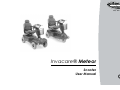
Yes, You Can.® Invacare® Meteor Scooter User Manual How can you get in touch with Invacare®? If you have any questions or need support, please contact your authorised Invacare® Dealer, who has the necessary know-how and equipment plus the special knowledge concerning your Invacare® product, and can offer you all-round satisfactory service. Should you wish to contact Invacare® directly, you can reach us in Europe at the following addresses and phone numbers. Mobitec Mobilitätshilfen GmbH Herzog Odilostrasse 101 A-5310 Mondsee Austria Fax: @: @: WWW: +43 6232 55 35 0 +43 6232 55 35 4 [email protected] [email protected] www.mobitec-austria.com Fax: @: WWW: +32 (0)50 83 10 10 +32 (0)50 83 10 11 [email protected] www.invacare.be Fax: @: @: WWW: +41 (0)61 48 77 08 0 +41 (0)61 48 77 08 1 [email protected] [email protected] www.mobitec-rehab.ch Invacare Aquatec Alemannenstraße 10 88316 Isny Deutschland Fax @: WWW: +49 (0)75 62 7 00 0 +49 (0)75 62 7 00 66 [email protected] www.invacare-aquatec.de Invacare® A/S Sdr. Ringvej 37 DK-2605 Brøndby Danmark (Kundeservice): Fax (Kundeservice): @: WWW: Invacare® n.v. Autobaan 22 B-8210 Loppem (Brugge) Belgium Mobitec Rehab AG Benkenstraße 260 CH-4108 Witterswil Switzerland 2 +45 (0)36 90 00 00 +45 (0)36 90 00 01 [email protected] www.invacare.dk Invacare® SA c/ Areny, s/n Polígon Industrial de Celrà E-17460 Celrà (Girona) ESPAÑA : Fax: @: WWW: +34 (0)972 49 32 00 +34 (0)972 49 32 20 [email protected] www.invacare.es Invacare® Poirier SAS Route de St Roch F-37230 Fondettes France : Fax : @: WWW: +33 (0)247 62 64 66 +33 (0)247 42 12 24 [email protected] www.invacare.fr Invacare® Ltd Pencoed Technology Park Pencoed Bridgend CF35 5HZ United Kingdom (Customer Service): Fax (Customer Service): @: @: WWW: +44 (0)1656 776 222 +44 (0)1656 776 220 [email protected] [email protected] www.invacare.co.uk Invacare Mecc San s.r.l. Via Dei Pini, 62 I - 36016 Thiene (VI) ITALIA Fax: @: WWW: +39 0445 38 00 59 +39 0445 38 00 34 [email protected] www.invacare.it Fax: @: WWW: +353 18 10 70 84 +353 18 10 70 85 [email protected] www.invacare.ie Invacare Ireland Ltd. Unit 5 Seatown Business Campus Seatown Rd, Swords County Dublin Ireland Invacare® AS Grensesvingen 9 Postboks 6230 Etterstad N-0603 Oslo Norge (Kundeservice): Fax (Kundeservice): @: WWW: Invacare® B.V. Celsiusstraat 46 NL-6716 BZ Ede Nederland : Fax: @: WWW: +47 (0)22 57 95 00 +47 (0)22 57 95 01 [email protected] www.invacare.no +31 (0)318 69 57 57 +31 (0)318 69 57 58 [email protected] www.invacare.nl 3 Invacare Portugal, Lda Rua Estrada Velha, 949 P-4465-784 Leça do Balio Portugal : : Fax: @: WWW: +351 225 1059 46 +351 225 1059 47 +351 225 1057 39 [email protected] www.invacare.pt Återförsäljare: Invacare® AB Fagerstagatan 9 S-163 91 Spånga Sverige (Kundtjänst): Fax (Kundtjänst): @: @: WWW: +46 (0)8 761 70 90 +46 (0)8 761 81 08 [email protected] [email protected] www.invacare.se Tillverkare: Invacare® Deutschland GmbH Kleiststraße 49 D-32457 Porta Westfalica Deutschland MÖLNDAL Fax: @: +46 (0)31 86 36 00 +46 (0)31 86 36 06 [email protected] LANDSKRONA Fax: @: +46 (0)418 285 40 +46 (0)418 180 89 [email protected] OSKARSHAMN Fax: @: 4 +46 (0)491 101 40 +46 (0)491 101 80 [email protected] Table of Contents Chapter 1 Introduction 1.1 1.2 1.3 1.4 1.5 1.6 2 5 21 22 Before driving for the first time..............................................................................................22 Taking Obstacles.....................................................................................................................23 Driving up and down gradients..............................................................................................24 Parking and stationary............................................................................................................25 4.4.1 Using the handbrake as a parking brake (option) ........................................................25 Pushing the scooter by hand 5.1 14 General Safety Notes ..............................................................................................................14 Safety information with regard to care and maintenance ...................................................17 Safety Information on Electromagnetic Interference...........................................................18 Safety Information on Driving and Freewheel Mode............................................................19 Key features Driving 4.1 4.2 4.3 4.4 8 Important symbols in this manual .........................................................................................10 Important symbols found on the vehicle ..............................................................................11 Type classification and permissible use...............................................................................12 Guarantee .................................................................................................................................12 Indications................................................................................................................................13 Life expectancy........................................................................................................................13 Safety Notes 2.1 2.2 2.3 2.4 3 4 Page 26 Disengaging Motors ................................................................................................................26 5 6 The Control Panel 6.1 6.2 6.3 6.4 7 8 8.2 6 36 Adjusting the backrest angle .................................................................................................36 Moving the seat position forwards or backwards................................................................37 Disengaging the seat to rotate it or remove it ......................................................................38 Adjusting the armrest width ...................................................................................................39 Adjusting the armrest height..................................................................................................40 Adjusting the seat height........................................................................................................41 Adjusting the suspension.......................................................................................................42 Electrical System 8.1 9 Control Panel Layout ..............................................................................................................27 6.1.1 Seat Lifter Button ..........................................................................................................28 6.1.2 Status Display...............................................................................................................28 6.1.3 Battery Charge Display.................................................................................................29 Driving the Scooter .................................................................................................................30 Diagnostics and Troubleshooting .........................................................................................31 6.3.1 Diagnosing Faults .........................................................................................................32 Error Codes and Diagnostic Codes.......................................................................................33 Adjustment features 7.1 7.2 7.3 7.4 7.5 7.6 7.7 27 43 Electronics Protection System ..............................................................................................43 8.1.1 The main fuse ...............................................................................................................44 Batteries ...................................................................................................................................44 8.2.1 What you need to know about batteries .......................................................................44 8.2.2 Charging the batteries ..................................................................................................46 8.2.3 Removing and fitting batteries ......................................................................................48 8.2.3.1 Removing the batteries............................................................................................49 8.2.3.2 How to handle damaged batteries correctly ............................................................51 Care and maintenance 52 10 Repair Instructions 10.1 54 Repairing a flat tyre .................................................................................................................54 10.1.1 Repairing punctures (pneumatic tyres of type 4.00 - 5) ...............................................55 10.1.1.1 Removal/refitting of rear wheel................................................................................55 10.1.1.2 Removal/refitting of front wheel (4-wheel version) ..................................................57 10.1.1.3 Removal/refitting of front wheel (3-wheel version) ..................................................59 10.1.1.4 Repairing punctured tyres .......................................................................................60 11 Disposal 12 Technical specifications 13 Inspections Performed 62 63 66 7 1 Introduction Dear user, First we would like to thank you for purchasing our product! We hope you will enjoy your new Scooter. This manual contains important hints and information on: • Safety • Operation • Care and maintenance. Please take care to read the operating manual thoroughly before starting out on your first journey. This product has been designed to fit the needs of different types of users with different requirements. The decision whether the model is suitable for the user may only be taken by medical specialists with appropriate aptitude. Invacare® or their statutory representatives can accept no liability in cases in which the mobility product has not been adapted to suit the user's handicaps. Some maintenance and settings can be carried out by the user. Certain adjustments do however require technical training and may only be carried out by your Invacare® specialist dealer. Damages and errors caused by nonobservance of the operating manual or as a result of incorrect maintenance are excluded from all guarantees. 8 This manual contains copyrighted information. It may not be reproduced or copied in whole or in part without the prior written consent of Invacare® or its authorised representative. It may also contain information that pertains to models sold only in certain countries. In this case the information will be clearly marked as pertaining to a particular country-specific version. We reserve the right to make any alterations on the grounds of technical improvements. 9 1.1 Important symbols in this manual WARNING! This symbol warns you of danger! • Always follow these instructions to avoid injury to the user or damage to the product! EXPLOSION HAZARD! This symbol warns you of an explosion hazard, which, for example, can be caused by excessive tyre pressure in a pneumatic tyre! • Always follow the instructions to avoid injury to the user or damage to the product! BURN HAZARD! This symbol warns you of burns due, for example, to leaking battery acid! • Always follow the instructions to avoid injury to the user or damage to the product! NOTE: This symbol identifies general information which is intended to simplify working with your product and which refers to special functions. Requirements: • This symbol identifies a list of various tools, components and items which you will need in order to carry out certain work. READ WELL BEFORE OPERATION! This symbol advises you to read information carefully. 10 1.2 Important symbols found on the vehicle This product has been supplied from an environmentally aware manufacturer that complies with the Waste Electrical and Electronic Equipment (WEEE) Directive 2002/96/CE. This product may contain substances that could be harmful to the environment if disposed of in places (landfills) that are not appropriate according to legislation. • The 'crossed out wheelie bin' symbol is placed on this product to encourage you to recycle wherever possible. • Please be environmentally responsible and recycle this product through your recycling facility at its end of life. 11 1.3 Type classification and permissible use This vehicle was designed for persons whose ability to walk is impaired, but who are still physically and mentally able to operate an electric vehicle. It has been classified according to EN 12184 as a Class C mobility product (for outdoor use). Because of its size it is less suitable for use in indoor environments, but has a longer driving range and the ability to overcome larger and more difficult obstacles in outdoor settings. You can find exact information on speed, turning radius, range, safe climbing ability, maximum obstacle height and permissible operating conditions in chapter "Technical specifications" on page 63. Please also pay attention to all safety information in chapter "Safety Notes" starting from page 14. The vehicle was successfully tested according to German and international standards as to its safety. It was also tested successfully according to EN60529 IPX4 as to its resistance to spray water, and is therefore well suited for typical middle European weather conditions. When equipped with an appropriate lighting system, the vehicle is suitable for use on public roads. 1.4 Guarantee The terms and conditions of the guarantee are part of the general terms and conditions particular to the individual countries in which this product is sold. 12 1.5 Indications The use of this mobility product is recommended for the following indications: The inability or a greatly restricted ability to walk within the scope of the basic requirement to be able to move within one’s own four walls. The need to leave the dwelling place in order to get some fresh air during a short walk or to reach those places generally to be found at close distance to the dwelling and where everyday business is carried out. Provision of electric wheelchairs for interior and exterior areas is advisable if the use of handoperated wheelchairs is no longer possible on account of the disability, yet proper operation of an electromotive drive unit is still practicable. 1.6 Life expectancy We estimate a life expectancy of five years for this product, provided it is used in strict accordance with the intended use as set out in this document and all maintenance and service requirements are met. The estimated life expectancy can be exceeded if the product is carefully used and properly maintained, and provided technical and scientific advances do not result in technical limitations. The life expectancy can also be considerably reduced by extreme or incorrect usage. The fact that we estimate a life expectancy for this product does not constitute an additional warranty. 13 2 Safety Notes READ WELL BEFORE OPERATION! 2.1 General Safety Notes Danger of injury if this scooter is used in any other way than the purpose described in this manual! • Adhere strictly to the instructions in this user manual! Danger of injury if the scooter is driven when your ability to drive is impaired by medication or alcohol! • Never drive any vehicle under the influence of medication or alcohol! Danger of damage or injury if the scooter is accidentally set into motion! • Switch the power system off before you get in, get out or handle awkward objects! • Be aware that the motor brakes are automatically deactivated when the motors are disengaged. For this reason, freewheel operation is only recommended on flat surfaces, never on gradients. Never leave your vehicle on a gradient with its motors disengaged. Always reengage the motors immediately after pushing the vehicle. 14 Danger of injury if the On/Off Button is pressed while the vehicle is in motion, due to it coming to an abrupt, sharp stop! • If you have to brake in an emergency, simply pull the handbrake until the scooter comes to a halt! Only switch the vehicle off while in motion as a last resort! Danger of injury if the scooter is transported in another vehicle with the occupant seated in it! • Never transport the scooter with the occupant seated in it! Danger of injury if maximum permissible load is exceeded! • Do not exceed the maximum permissible load (see "Technical specifications" on page 63)! Danger of injury when lifting heavy components! • When maintaining, servicing or lifting any part of your scooter, take into account the weight of the individual components, especially the batteries! Be sure at all times to adopt the correct lifting posture and ask for assistance if necessary! Danger of injury if you fall off the scooter! • If restraining systems are installed (such as seat belts), use them each time you drive the scooter. 15 Danger of injury by moving parts! • Make sure that no injury is incurred by moving parts of the scooter, like wheels or a Seat Lifter, especially when children are around! Danger of fire or breaking down due to electric devices being connected! • Do not connect any electric devices to your vehicle that are not expressly certified by Invacare® for this purpose! Have all electrical installations done by your authorised Invacare® Dealer! Danger of technical failure and injury if unauthorised spare parts and components are used! • Only use original Invacare® spare parts, which have been approved for use with this vehicle! 16 2.2 Safety information with regard to care and maintenance Danger of accident and loss of guarantee if maintenance is insufficient! • For reasons of safety and in order to avoid accidents which result from unnoticed wear, it is important that this electric mobility product undergoes an inspection once every year under normal operating conditions (see inspection plan contained in service instructions). • Under difficult operating conditions such as daily travel on steep slopes, or in the case of use in medical care cases with frequently changing wheelchair users, it would be expedient to carry out intermediate checks on the brakes, accessories and running gear. • If the mobility product is to be operated on public roads, the vehicle driver is responsible for ensuring that it is in an operationally reliable condition. Inadequate or neglected care and maintenance of the mobility product will result in a limitation of the manufacturer's liability. 17 2.3 Safety Information on Electromagnetic Interference This electric vehicle was successfully tested in accordance with International standards as to its compliance with Electromagnetic Interference (EMI) Regulations. However, electromagnetic fields, such as those generated by radio and television transmitters, and cellular phones, can influence the functions of electric vehicles. Also, the electronics used in our vehicles can generate a low level of electromagnetic interference, which however will remain within the tolerance permitted by law. For these reasons we ask you to please observe the following precautions: WARNING: Danger of malfunction due to electromagnetic interference! • Do not switch on or operate portable transceivers or communication devices (such as radio transceivers or cellular phones) when the vehicle is switched on. • Avoid getting near strong radio and television transmitters. • In case the vehicle should be set in motion unintentionally or the brakes are released, switch it off immediately. • Adding electrical accessories and other components or modifying the vehicle in any way can make it susceptible to electromagnetic interference. Keep in mind that there is no sure way to determine the effect such modifications will have on the overall immunity of the electronic system. • Report all occurrences of unintentional movement of the vehicle, or release of the electric brakes to the manufacturer. 18 2.4 Safety Information on Driving and Freewheel Mode Danger of injury if the vehicle tips over! • Only ever negotiate gradients up to the maximum tilt-resistant gradient and only with the backrest in an upright position, and the seat lifter in the lowest position (if installed)! • Only ever drive downhill at a maximum of 2/3rds of the top speed! Avoid abrupt braking or accelerating on gradients! • If at all possible, avoid driving on slippery surfaces (such as snow, gravel, ice etc.) where there is a danger of you losing control over the vehicle, especially on a gradient! If driving on such a surface is inevitable, then always drive slowly and with the utmost caution! • Never attempt to overcome an obstacle when on an uphill or downhill gradient! • Never attempt to drive up or down a flight of steps! • Always approach obstacles straight on! Ensure that the front wheels and rear wheels move over the obstacle in one stroke, do not stop halfway! Do not exceed the maximum obstacle height (see "Technical specifications" on page 63)! • Avoid shifting your centre of gravity as well as abrupt changes of direction when the vehicle is in motion! 19 Danger of injury if the vehicle tips over! (Continued) • Never use the vehicle to transport more than one person! • Do not exceed the maximum permissible load! • When loading the vehicle, always distribute the weight evenly! Always try to keep the centre of gravity of the vehicle in the middle, and as close to the ground as possible! • Note that the vehicle will brake or accelerate if you change the Driving Speed while it is in motion! Danger of injury if you collide with an obstacle when driving through narrow passages such as doorways and entrances! • Drive through narrow passages in the lowest Driving Speed and with due caution! CAUTION: The centre of gravity for the scooter is higher than that of an electric wheelchair! There is an increased tipping hazard when negotiating bends! • Reduce speed before negotiating bends! Only accelerate when you have come out of the bend! CAUTION: Danger of tipping! Anti tip wheels (stabilisers) are only effective on firm ground! They sink in on soft ground such as grass, snow or mud if the electrical vehicle rests itself on them. They lose their effect and the electrical vehicle can tip over. • Only drive with extreme care on soft ground, especially during uphill and downhill journeys. In the process pay increased attention to the tip stability of the electric vehicle. 20 3 Key features 1) Driving lever 2) Lever for adjusting steering column inclination 3) Control panel 4) Handbrake / wheel lock 5) Keyswitch (ON/OFF) 6) Release lever for sliding seat rails (front right below seat) 7) Release lever for swivelling and removing seat (right below seat) 8) Disengaging lever 21 4 Driving 4.1 Before driving for the first time... Before you take your first trip, you should familiarise yourself well with the operation of the vehicle and with all operating elements. Take your time to test all functions and driving modes. NOTE: If installed, make sure to properly adjust and use the posture belt each time you use the wheelchair. Sitting Comfortably = Driving Safely Before each trip, make sure that: You are within easy reach of all operating controls. 22 • The battery charge is sufficient for the distance intended to be covered. • The posture belt (if installed) is in perfect order. 4.2 Taking Obstacles Your Invacare® Meteor can climb obstacles and kerbstones up to 11 cm in height. CAUTION: Danger of Tipping Over! • Never approach obstacles at an angle but at 90 degrees as shown below. • Put your backrest into an upright position before climbing an obstacle. Driving up over an obstacle • Correct Approach the kerb or obstacle slowly head-on. Shortly before the front wheels touch the obstacle, increase the speed and reduce only after the rear wheels have also climbed the obstacle. Driving down off of an obstacle • Approach the kerb or obstacle slowly head-on. Before the front wheels touch the obstacle, reduce speed and keep it until also the rear wheels have come down off of the obstacle. Incorrect 23 4.3 Driving up and down gradients The maximum safe slope for the Invacare® Meteor depends on the version and the load capacity: 10 km/h versions: • 3-wheeler (up to 175 kg load): 15° (26%) • 4-wheeler (up to 200 kg load): 15° (26%) 12.8 km/h (8 MPH, UK) and 15 km/h versions: • 3- and 4-wheeler (up to 150 kg load): 12° (21%) • 3-wheeler (up to 175 kg load): 10° (17%) • 4-wheeler (up to 200 kg load): 10° (17%) WARNING: Danger of tipping over! • Only ever drive downhill at a maximum of 2/3rds of the top speed! • Always return the backrest of your seat to an upright position before ascending slopes! We recommend that you lean the backrest slightly to the rear before descending slopes! • Never attempt to ascend or descend a slope on slippery surfaces or where there is a danger of skidding (such as wet pavement, ice etc)! • Avoid trying to get out of the vehicle on an incline or a gradient! • Always drive in a straight direction along the road or path you are travelling on, rather than attempting to zigzag! • Never attempt to turn around on an incline or a slope! 24 4.4 Parking and stationary When parking your vehicle or if your vehicle is stationary for a prolonged period: 4.4.1 • Switch the vehicle's power system off (key switch). • Activate the parking brake (if available). Using the handbrake as a parking brake (option) Activating the brake • Pull the handbrake lever (1) and hold it. • While holding the handbrake lever, press the latching pin (2) down. The lever is latched in place. Releasing the brake • Pull the handbrake lever briefly and let it go. The latching pin pops up. The lever is released. 25 5 Pushing the scooter by hand The motors of the scooter are equipped with automatic brakes, preventing the scooter from rolling away out of control when the power supply is switched off. When pushing the scooter, the magnetic brakes must be disengaged. 5.1 Disengaging Motors Danger of the vehicle running away! • When the motors are disengaged (for push operation whilst freewheeling), the electromagnetic motor brakes are deactivated! When the vehicle is parked, the levers for engaging and disengaging the motors must without fail be locked firmly into the "DRIVE" position (electromagnetic motor brakes activated)! The lever for engaging and disengaging the motor is located on the right-hand side at the rear. Disengaging the motor • Make sure that the power supply is turned off (keyswitch). • Press the lever (1) forwards. Engaging the motor • 26 Pull the lever to the rear. 6 The Control Panel 6.1 Control Panel Layout 1) Seat Lifter button (if installed) 2) Battery charge indicator 3) Hazard flashers 4) Horn 5) Right turn signal 6) Driving speed adjustment 7) Throttle lever 8) Plug for external charger 9) Reduced Speed Mode 10) Left turn signal 11) Lights 27 6.1.1 Seat Lifter Button • Press the button to activate the Seat Lifter (if installed). The LED above the button lights up. • Raise or lower the seat using the throttle lever. • Press the button once again to de-activate the Seat Lifter. The throttle lever reverts back to driving mode. NOTE If the Seat Lifter is not lowered entirely, then the speed of the scooter is automatically reduced to lower the risk of tipping over. This is indicated by the LED just above the "Reduced Speed Mode" button flashing. Lower the Lifter completely to restore speed to it's normal level. The LED will go out. 6.1.2 Status Display NOTE The leftmost diode of the battery charge display serves as an error message display (status display). For an explanation of the Error Codes please see chapter "Error Codes and Diagnostic Codes" on page 33. 28 6.1.3 Battery Charge Display • • • All diodes lit: full driving range Only red and yellow diodes lit: decreased drive range. Charge batteries at end of journey. Only red diodes lit / flashing: battery reserve = very low drive range! Charge batteries immediately! NOTE Total discharge protection: After a certain drive time on reserve battery power the electronics switches off the drive automatically and the scooter will be immobile. 29 6.2 Driving the Scooter • Switch on the power supply (key switch). The displays on the Control Panel light up. The scooter is ready to drive. NOTE If the scooter does not respond after switching on, check the status display (see chapter "Status Display" on page 28 and chapter "Diagnostics and Troubleshooting" on page 31). • Set the driving speed with the speed adjustment knob. • Gently pull the right driving lever towards you to drive forwards. • Gently pull the left driving lever towards you to drive backwards. NOTE The controller is programmed with standard values ex-works. Your Invacare® Dealer can program it to fit your requirements. NOTE: • To brake quickly, simply let go of the driving lever. It will automatically return to the middle position. The scooter will brake. • 30 To brake in an emergency, follow the above and pull the handbrake lever until the scooter comes to a halt. 6.3 Diagnostics and Troubleshooting The electronics system provides diagnostics information to assist technicians to diagnose and correct faults within the scooter system. The existence of a fault will cause the status light to flash in bursts, separated by a pause. The nature of the fault is indicated by the number of flashes in each burst, also referred to as the Flash Code. Depending on the severity of the fault and impact on user safety, the electronic system will react differently. It may… • Simply display the Flash Code as a warning and allow normal driving and operation. • Display the Flash Code, stop the scooter and prevent driving until the electronic system has been turned off and then back on again. • Display the Flash Code, stop the scooter and prevent driving until the fault has been fixed. For detailed descriptions of what each Flash Code means, and the probable cause and remedy, see Section "Error Codes and Diagnostic Codes" on page 33. 31 6.3.1 Diagnosing Faults Use the following troubleshooting guide if the scooter fails to operate. NOTE Turn the key switch on before beginning any diagnostics. If the Status Light is OFF Check that the key switch is turned ON. Check that all cables are connected correctly. If only the leftmost diode of the battery charge display is PERMANENTLY ON Contact your authorised Invacare® Dealer If the leftmost diode of the battery charge display is FLASHING Count the number of flashes and refer to the next section. 32 6.4 Error Codes and Diagnostic Codes Blink code 1 2 3 Fault Consequence for the Scooter Battery must be Continues to • charged drive Battery voltage too Stops driving • low • Battery voltage too Stops driving high • • Comments The batteries are discharged. Charge the battery as soon as possible. The batteries are depleted. Charge batteries. If you switch the Scooter off for a few minutes, the battery can often recuperate to such a stage that a short journey is still possible. The battery voltage is too high. If the battery charger is connected, disconnect it from the Scooter. The electronic system charges the batteries when running downhill and when braking. This fault is caused when the battery voltage becomes too high during this process. Switch the Scooter off and on again. 33 Blink code 4 Fault Power time exceeded Consequence for the Scooter Stops driving • • 5 Brake failure Stops driving • • • 6 No neutral position Stops driving when switching Scooter on. • • 34 Comments The maximum current was exceeded over too long a period, probably because the motor was overloaded or has been working against an immovable resistance. Switch the scooter off, wait a few minutes and then switch on again. The electronic system has determined a motor short-circuit. Check the wiring harness for short-circuit and check the motor. Contact your Invacare® dealer. Ensure that the disconnection lever is pressed in. There is a defect in the braking coil or in the cabling. Check the magnetic brake and cabling for open or short-circuited circuitry. Contact your Invacare® dealer. Drive lever is not in neutral when the keyswitch was turned. Put the drive lever in neutral, turn the power off and then turn on again. It may be necessary to recalibrate the drive lever. Contact your Invacare® dealer. Blink code 7 Fault Fault in speed potentiometer Consequence for the Scooter Stops driving • • 8 Motor voltage error Stops driving • 9 Miscellaneous internal fault Push/freewheel mode error Stops driving • Stops driving • 10 Comments The drive lever electronics could be faulty or incorrectly connected. Check the cabling for open or short-circuited circuitry. Potentiometer is not correctly adjusted. Put the potentiometer into the centre position. The motor or its cabling is defective Check the cabling for open or shortcircuited circuitry. Contact your Invacare® dealer. The Scooter has exceeded the permissible maximum speed during pushing or freewheeling. Switch the electronics system off and on again. 35 7 Adjustment features 7.1 Adjusting the backrest angle The backrest is held firm by a metal plate on both sides. Both plates have four holes which allow the backrest to be adjusted for various angles. You can do this by selecting various combinations for the holes. Requirements • Allen key 4 mm • Engineer's spanner 10 mm 36 • Loosen the bolts (1) which hold the backrest on both sides using the engineer's spanner and the Allen key. • Move the backrest into the required position. • Reinsert the bolts and tighten. 7.2 Moving the seat position forwards or backwards The disengaging lever for adjusting the seat is located front right below the seat • Pull the lever (1) to disengage the seat. • Slide the seat forwards or backwards into the required position. • Let go the lever again to lock the seat into its required position. 37 7.3 Disengaging the seat to rotate it or remove it The seat can be turned to one side to make getting in and out of the scooter easier. The seat is also easier to remove from this position. The lever for disengaging the seat is located under the seat (1) on the right. 38 • Pull the lever forwards to disengage the seat. • Turn the seat to one side. • If you want to remove the seat, hold it firmly by the backrest or front edge and remove it upwards. 7.4 Adjusting the armrest width The hand wheels for adjusting the armrests are located under the seat (1). • Turn the hand wheels to loosen the fixing for the armrest. • Adjust the armrests to the required width. • Retighten the handwheels 39 7.5 Adjusting the armrest height The hand wheels for adjusting the armrest height are located on the armrests (1). 40 • Turn the hand wheels to loosen the fixing for the armrest (1). • Adjust the armrests to the required height. • Retighten the handwheels 7.6 Adjusting the seat height The seat height can be adjusted to the following heights (measured from chassis / floor): • • • • 46 / 64 cm 48 / 66 cm 49 / 68 cm 51 / 71 cm WARNING! Danger of disengaging the drive unintentionally! • Never use the topmost hole in the tube! In this position the seat is too low and has too little clearance to the cowling as well as to the declutching lever! Requirements: • 2x open-ended spanners 17 mm • Removing the seat • Remove the battery and motor compartment cover. • Remove the seat pillar locking bolt (1) using both open-ended spanners. 41 7.7 • Adjust the seat height. • Reinsert the bolt and tighten. Adjusting the suspension The Meteor suspension can be individually adjusted. These adjustments should only be carried out by trained specialists. Please contact your authorised Invacare specialist dealer. 42 8 Electrical System 8.1 Electronics Protection System The vehicle's electronics are equipped with an overload-protection system. If the motors are put under considerable strain for a longer period of time (for example, when driving up a steep hill) and especially when the ambient temperature is high, then the electronic system could overheat. In this case the vehicle's power is reduced gradually until it finally comes to a halt. The Status Display shows a corresponding error code (see chapter "Error Codes and Diagnostic Codes" on page 33). By switching the power supply off and back on again, the error code is cancelled and the electronics are switched back on. It will take approximately five minutes until the electronics have cooled down enough for the motors to restore full power again. When the motors are stalled by an insurmountable obstacle, such as a high kerb, and the vehicle driver allows the motors to strain against this hindrance for more than 20 seconds without moving, then the electronics will automatically switch off to prevent the motors from being damaged. The Status Display shows a corresponding error code (see chapter "Error Codes and Diagnostic Codes" on page 33). By switching off and back on again, the error code is cancelled and the electronics are switched back on. 43 8.1.1 The main fuse The entire electric system is protected against overload by two master fuses. The master fuses are mounted on the positive battery cables. NOTE A defective main fuse may be replaced only after checking the entire electric system. An Invacare® specialised dealer must perform the replacement. You can find information on the fuse type in chapter "Technical specifications" starting on page 63. 8.2 Batteries 8.2.1 What you need to know about batteries Power is supplied by two 12V batteries. The batteries are maintenance-free and only need regular charging. New batteries should always be fully charged once before their first use. New batteries will be at their full capacity after having run through approx. 10 - 20 charging cycles. How fast the batteries will be discharged will depend on many circumstances, such as ambient temperature, condition of the surface of the road, tyre pressure, weight of the driver, way of driving and utilisation of lighting, etc. 44 NOTE The batteries supplied with your electric vehicle are not hazardous goods. This classification is based on the German GGVS Hazardous Goods Road Transport Ordinances, and the IATA/DGR Hazardous Goods Rail Transport / Air Transport Ordinances. Batteries may be transported without restrictions, whether by road, rail or by air. Individual transport companies have, however, guidelines which can possibly restrict or forbid certain transport procedures. Please ask the transport company regarding each individual case. Pay attention to the Battery Charge Indicator! Make sure to charge the batteries when the Battery Charge Indicator shows that battery charge is low. We recommend charging the batteries after each trip, as well as each night over night. Depending on the level of discharge, it can take up to 12 hours until the batteries are fully charged again. Protect your charger from sources of heat such as heaters and direct sunlight. If the battery charger overheats, charging current will be reduced and the charging process delayed. To avoid damaging the batteries, never allow them to be fully discharged. Do not drive on heavily discharged batteries if it is not absolutely necessary, as this will strain the batteries unduly and shorten their life expectancy. In case your vehicle is not used for a longer period of time, then the batteries must be charged at least once a month to maintain a full charge. Alternatively, the vehicle can stay connected to the charger. The batteries cannot be overcharged with the specified charger. Please use only charging devices in Class 2. This class of chargers may be left unattended during charging. All charging devices which are supplied by Invacare® comply with these requirements. 45 8.2.2 Charging the batteries • Make sure you read and understand the battery charger's User's Manual, if supplied, as well as the safety notes on the front and rear panels of the charger! WARNING: Danger of explosion and destruction of batteries if the wrong battery charger is used! • Only ever use the battery charger supplied with your vehicle, or a charger that has been approved by Invacare®. Danger of electric shock and damage to the battery charger if it is allowed to get wet! • Protect the battery charger from water. • Always charge in a dry environment. Danger of short circuit and electric shock if the battery charger has been damaged! • Do not use the battery charger if it has been dropped or damaged. Danger of fire and electric shock if a damaged extension cable is used! • Only ever use an extension cable if it is absolutely necessary. In case you must use one, make sure it is in good condition. 46 The Meteor has two sockets for charging the batteries. One is located on the rear edge of the operating console (1) (maximum charge current 8A). The other is located on the front side of the battery and motor compartment (2) (maximum charge current 15A). Connecting the battery charger • Switch off the Scooter at the operating console. • Connect the battery charger to the Scooter. • Connect the battery charger to the mains. Disconnecting the battery charger from the scooter • First disconnect the battery charger from the mains. • Then unplug the battery charger from the scooter. 47 8.2.3 Removing and fitting batteries WARNING: Danger of injury if the batteries are not handled correctly during assembly and maintenance work! • New batteries should be installed by authorised technicians! • Observe the warnings on the batteries! • Take into account the heavy weight of the batteries! • Only ever use the battery type defined in the technical specifications (see "Technical specifications" on page 63)! Danger of fire and burns if battery terminals are short-circuited! • DO NOT short-circuit battery terminals with a tool! WARNING: Corrosion and burns from acid leakage if batteries are damaged! • Remove clothes that have been soiled by acid immediately. After contact with skin: • Immediately wash affected area with lots of water. After contact with eyes: • Immediately rinse eyes under running water for several minutes; consult a physician. 48 8.2.3.1 Removing the batteries Requirements: • 2x open-ended spanners 11 mm • Remove seat (see chapter "Releasing seat for turning or removal" on page "38") • Remove the battery and motor compartment covers by pulling on the rear edge. • Disconnect the two battery cable plug connections (1). 49 • Release the battery holder strap. • Removing the batteries. • Loosen the black cable battery clamp on the negative battery terminal with the open-ended spanner, and remove the cable. • Loosen the red cable battery clamp on the positive battery terminal with the open-ended spanner, and remove the cable. • Repeat the procedure for the other battery NOTE: Replacing new batteries takes place in reverse order. 50 8.2.3.2 How to handle damaged batteries correctly WARNING: Corrosion and burns from acid leakage if batteries are damaged! • Remove clothes that have been soiled by acid immediately. After contact with skin: • Immediately wash affected area with lots of water. After contact with eyes: • Immediately rinse eyes under running water for several minutes; consult a physician. • Always wear safety goggles and appropriate safety clothing when handling damaged batteries. • Place damaged batteries in an acid-resistant receptacle immediately after removing them. • Only ever transport damaged batteries in an appropriate acid-resistant receptacle. • Wash all objects that have come into contact with acid with lots of water. Disposing of dead or damaged batteries correctly Dead or damaged batteries can be given back to your dealer or directly to Invacare®. 51 9 Care and maintenance NOTE: Have your vehicle checked once a year by an authorised Invacare® dealer in order to maintain it's driving safety and roadworthiness. Cleaning the vehicle When cleaning the vehicle, pay attention to the following points: • Only use a damp cloth and gentle detergent. • Do not use any abrasive or scouring liquids. • Do not subject the electronic components to any direct contact with water. • Do not use high-pressure cleaning devices. Disinfection Spray or wipe disinfection using a tested and recognised product is permitted. A list of the current permitted disinfectants is available from the Robert Koch Institute at http://www.rki.de. 52 Seat and backrest padding: • Check for perfect condition. Tyres: • Have tyres checked for specified air pressure (2,5 bar). Front wheels • Front wheels must spin smoothly. • If wheels wobble or do not spin easily, adjust steering pivot pin or front wheel bearing. Rear wheels: • Test wheel for firm seat on the axle drive shaft. • Rear wheels must spin without wobbling Electronics / Electrical System: • Check all plug connections for condition and firm connection. • Have batteries been fully charged before the daily operation? • Are all holders, screws firmly fixed, tight and safe? • Are all electric bulbs of the lighting system (if applicable) in working order? Cleaning: • Clean all parts carefully. Monthly Weekly When Delivered Maintenance Jobs Before every trip Before each trip When necessary Once a year you should have your vehicle inspected and serviced by your authorised dealer. A complete checklist of necessary maintenance work can be found in the Service Manual, which can be obtained from Invacare®. 53 10 Repair Instructions The following are instructions on repairs that can be performed by the user. For the specifications of spare parts please see "Technical specifications" on page 63, or consult the Service Manual, available from Invacare® (in this connection please see the addresses and phone numbers in section "How can you get in touch with Invacare®?" on page 2). In case you require assistance, please contact your Invacare® Dealer. 10.1 Repairing a flat tyre WARNING: Danger of damage or injury if the vehicle is accidentally set into motion during repairs! • Switch the power off (ON/OFF Button)! • Engage the motors! • Secure the vehicle against rolling away by placing wedges under the wheels! 54 10.1.1 Repairing punctures (pneumatic tyres of type 4.00 - 5) 10.1.1.1 Removal/refitting of rear wheel CAUTION: It is possible to damage the scooter if the wheels are re-fixed without using copper paste after repairing a flat tyre! • When refitting the wheel, copper paste must be applied to the drive shaft or axle! This ensures that the wheel rim does not solidly jam onto the axle over time so that it cannot be removed! Requirements: • Spanner 19 mm • Rubber hammer • Copper paste • Jack the scooter up and place a wooden block or similar under it to support it. • Remove the wheel locknut (1) with a 19 mm open-ended spanner. • Remove the wheel. It may be necessary to carefully free the wheel off the axle by tapping lightly with the rubber hammer on the rear face of the wheel 55 Problems when removing wheel? It may be necessary to use a special tool Please ask your Invacare® dealer to help you. Reassembly Reassembly takes place in reverse order. Make sure that you refit the wheel on the same side and for the same direction of travel as previously. 56 10.1.1.2 Removal/refitting of front wheel (4-wheel version) CAUTION: It is possible to damage the scooter if the wheels are re-fixed without using copper paste after repairing a flat tyre! • When refitting the wheel, copper paste must be applied to the drive shaft or axle! This ensures that the wheel rim does not solidly jam onto the axle over time so that it cannot be removed! Requirements: • Open spanner, 17 mm. • Rubber hammer • Copper paste • Jack the scooter up and place a wooden block or similar under it to support it. • Remove the wheel locknut (1) with a 17 mm open-ended spanner. • Remove wheel. It may be necessary to carefully free the wheel off the axle by tapping lightly with the rubber hammer on the rear face of the wheel 57 Reassembly Reassembly takes place in reverse order. Make sure that you refit the wheel on the same side and for the same direction of travel as previously. 58 10.1.1.3 Removal/refitting of front wheel (3-wheel version) Requirements: • 2x open-ended spanners 17 mm • Carefully tip the scooter onto one side. • Remove the wheel locknuts (1) using both open-ended spanners, then remove the wheel from the fork. Reassembly Reassembly takes place in reverse order. Make sure that the wheels are reassembled to give the same direction of travel as previously. 59 10.1.1.4 Repairing punctured tyres Requirements (general) • inner tube repair set or a new inner tube • talcum powder • open-ended spanner, 13 mm 60 • Remove valve cap. • De-inflate the tyre by pressing in the centre valve pin. • Remove the four nuts (1) on the rear of the wheel using the 13 mm open-ended spanner. • Remove both wheel rim halves out of the tyre and remove the inner tube. • Repair the inner tube and refit in the wheel, or replace it with a new inner tube. Did the old inner tube get wet during the repair? If you repaired the old inner tube and reused it, and it became wet during repair, it is much easier to refit it into the wheel if you lightly powder it with talcum powder. • Refit the wheel rim parts from outside into the tyre. • Pump up the tyre lightly. • Reinsert the nuts and bolts which hold the wheel rim together and tighten fully. • Make sure that the tyre is properly located on the wheel rim. • Inflate the tyre up to the recommended tyre pressure (3.5 bar or 50 psi). • Check to make sure that the tyre is still located properly on the wheel rim. • Screw the valve cap back on. • Reassemble the wheel. 61 11 62 Disposal • The equipment wrapping is potentially recyclable. • The metal parts are used for scrap metal recycling. • The plastic parts are used for plastic recycling. • Electric components and printed circuit boards are disposed of as electronic scrap. • Exhausted or damaged batteries can be returned to your medical equipment supplier or Invacare®. • Disposal must be carried out in accordance with the respective national legal provisions. • Ask your city or district council for details of the local waste management companies. 12 Technical specifications Electrical system Motor (10 km/h) Motor (12.8 km/h, 8 MPH, UK) Motor (15 km/h) Batteries 3-wheeler version 4-wheeler version • 400 W • 400 W • 400 W • 400 W • • • • Main fuses (10 km/h) • Main fuses (12.8 km/h, • 8 MPH, UK) Main fuses (15 km/h) • Weight Without batteries, • without seat Without batteries • With 70 Ah batteries • Weight of heaviest part • Maximum load • (operating load) 400 W 2 x 50 AH 2 x 60 AH 2 x 70 AH 80 A 80 A • • • • • • 80 A • 80 A 60 kg* • 65 kg* 80 kg 127 kg 21.4 kg 175 kg • • • • 400 W 2 x 50 AH 2 x 60 AH 2 x 70 AH 80 A 80 A 85 kg 132 kg 25 kg 200 kg 63 Dimensions Height Width Length (with bumper and anti-tip device) Seat height (measured from chassis / from floor, manually adjustable) Backrest height (without headrest) Backrest height (with headrest) Backrest angle (manually adjustable) Seat width Seat depth Armrest height Tyres Tyre pressure 64 3-wheeler version 4-wheeler version • 123 cm* • 65.5 cm* • 141 cm* • 123 cm* • 65.5 cm* • 146 cm* • • • • • • • • • • 46 / 64 cm* 48 / 66 cm* 49 / 68 cm* 51 / 71 cm* 47 cm* 46 / 64 cm* 48 / 66 cm* 49 / 68 cm* 51 / 71 cm* 47 cm* • 63 cm* • 63 cm* • 0°, 10°, 15°, 30° • 0°, 10°, 15°, 30° • 44-55 cm* • 50 cm* • 24-30 cm* • 44-55 cm* • 50 cm* • 24-30 cm* • 3.5 bar (40 psi) • 3.5 bar (40 psi) 3-wheeler version Travelling performance Speed • 10 km/h • 12.8 km/h (8 MPH, UK) • 15 km/h Max. tilt-resistant climbing ability 10 km/h version • up to 175 kg operating load: 15° (26%) 12.8 km/h (8 MPH, UK) and • up to 150 kg operating load: 15 km/h versions 12° (21%) • up to 175 kg operating load: 10° (17%) Maximum obstacle height • 11 cm Tightest turning radius • 130 cm Drive range in accordance with ISO 7176** 10 km/h version 50 Ah batteries • 30 km 60 Ah batteries • 35 km 70 Ah batteries • 40 km 12.8 (8 MPH, UK) and 15 km/h versions 50 Ah batteries • 35 km 60 Ah batteries • 45 km 70 Ah batteries • 50 km * Approximate values. 4-wheeler version • 10 km/h • 12.8 km/h (8 MPH, UK) • 15 km/h • up to 200 kg operating load: 15° (26%) • up to 150 kg operating load: 12° (21%) • up to 200 kg operating load: 10° (17%) • 11 cm • 161 cm • 30 km • 35 km • 40 km • 35 km • 45 km • 50 km ** Note: The scooter drive range is heavily dependent on various factors such as the battery charger status, the environmental temperature, the flatness of the route chosen, the state of the roads, the tyre pressure, the driver's weight, driving style and use of batteries for lighting, actuators etc. 65 13 Inspections Performed It is confirmed by stamp and signature that all jobs listed in the inspection schedule of the Service and Repair Instructions have been properly performed. The list of the inspection jobs to be performed can be found in the Service Manual which is available through Invacare®. Delivery Inspection 1st Annual Inspection Stamp of authorised Dealer / Date / Signature Stamp of authorised Dealer / Date / Signature Stamp of authorised Dealer / Date / Signature Stamp of authorised Dealer / Date / Signature Stamp of authorised Dealer / Date / Signature Stamp of authorised Dealer / Date / Signature 2nd Annual Inspection 4th Annual Inspection 66 3rd Annual Inspection 5th Annual Inspection 67 English Order No. of this Manual: 1423448.DOC Release Date: 27.11.09