1
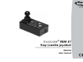
Yes, You Can.® Invacare® REM 41 Tray/centre joystick Remote User manual How can you get in touch with Invacare®? If you have any questions or need support, please contact your authorised Invacare® Dealer, who has the necessary know-how and equipment plus the special knowledge concerning your Invacare® product, and can offer you all-round satisfactory service. Should you wish to contact Invacare® directly, you can reach us in Europe at the following addresses and phone numbers. 2 Invacare Austria GmbH Herzog Odilostrasse 101 A-5310 Mondsee Austria : Fax: @: WWW: +43 6232 5 53 50 +43 6232 5 53 54 [email protected] www.invacare.at Invacare n.v. Autobaan 22 B-8210 Loppem (Brugge) Belgium : Fax: @: WWW: +32 (0)50 83 10 10 +32 (0)50 83 10 11 [email protected] www.invacare.be Invacare AG Benkenstraße 260 CH-4108 Witterswil Switzerland : Fax: @: WWW: +41 (0)61487 70 80 +41 (0)61487 70 81 [email protected] www.invacare.ch Invacare GmbH Alemannenstraße 10 88316 Isny Deutschland Fax @: WWW: +49 (0)7562 70 00 +49 (0)7562 7 00 66 [email protected] www.invacare.de Invacare A/S Sdr. Ringvej 37 DK-2605 Brøndby Danmark (Kundeservice): Fax (Kundeservice): @: WWW: Invacare® SA c/ Areny s/n Polígon Industrial de Celrà E-17460 Celrà (Girona) ESPAÑA : Fax: @: WWW: +45 (0)36 90 00 00 +45 (0)36 90 00 01 [email protected] www.invacare.dk +34 (0)972 49 32 00 +34 (0)972 49 32 20 [email protected] www.invacare.es Invacare® Poirier SAS Route de St Roch F-37230 Fondettes France : Fax: @: WWW: Invacare® Ltd Pencoed Technology Park Pencoed Bridgend CF35 5AQ United Kingdom (Customer services): Fax (Customer services): @: WWW: Invacare Mecc San s.r.l. Via dei Pini, 62 I - 36016 Thiene (VI) ITALIA : Fax: @: WWW: +39 0445 38 00 59 +39 0445 38 00 34 [email protected] www.invacare.it Invacare Ireland Ltd. Unit 5 Seatown Business Campus Seatown Rd, Swords County Dublin Ireland : Fax: @: WWW: +353 18 10 70 84 +353 18 10 70 85 [email protected] www.invacare.ie Invacare® AS Grensesvingen 9 Postboks 6230 Etterstad N-0603 Oslo Norge (Kundeservice): Fax (Kundeservice): @: @: WWW: +47 (0)22 57 95 00 +47 (0)22 57 95 01 [email protected] [email protected] www.invacare.no Invacare® B.V. Celsiusstraat 46 NL-6716 BZ Ede Nederland : Fax: @: @: WWW: +31 (0)318 69 57 57 +31 (0)318 69 57 58 [email protected] [email protected] www.invacare.nl : : Fax: @: WWW: +351 225 10 59 46 +351 225 10 59 47 +351 225 10 57 39 [email protected] www.invacare.pt Invacare Lda Rua Estrada Velha, 949 P-4465-784 Leça do Balio Portugal +33 (0)247 62 64 66 +33 (0)247 42 12 24 [email protected] www.invacare.fr +44 (0)1656 77 62 22 +44 (0)1656 77 62 20 [email protected] www.invacare.co.uk 3 Återförsäljare: Invacare® AB Fagerstagatan 9 S-163 91 Spånga Sverige (Kundtjänst): Fax (Kundtjänst): @: @: WWW: Tillverkare: Invacare® Deutschland GmbH Kleiststraße 49 D-32457 Porta Westfalica Deutschland MÖLNDAL : Fax: @: Eastern european countries 4 European Distributor Organisation (EDO) Kleiststraße 49 D-32457 Porta Westfalica Deutschland +46 (0)8 761 70 90 +46 (0)8 761 81 08 [email protected] [email protected] www.invacare.se +46 (0)31 86 36 00 +46 (0)31 86 36 06 [email protected] LANDSKRONA : Fax: @: +46 (0)418 2 85 40 +46 (0)418 1 80 89 [email protected] OSKARSHAMN : Fax: @: +46 (0)491 1 01 40 +46 (0)491 1 01 80 [email protected] Fax @: WWW: +49 (0)5731 75 45 40 +49 (0)5731 75 45 41 [email protected] www.invacare.de Table of Contents Chapter 1 Page Introduction .....................................................................................7 1.1 2 Important symbols in this manual .........................................................................................7 Fittings .............................................................................................9 2.1 The remote............................................................................................................................9 2.2 Operating and control panel ...............................................................................................11 2.2.1 Vehicle functions..............................................................................................................11 2.2.2 Electronic adjustment ......................................................................................................12 3 4 Quick reference .............................................................................12 Displays on the operating and control panel..............................15 4.1 4.2 4.3 5 Switches on the operating and control panel.............................18 5.1 5.2 5.3 5.4 5.5 5.6 5.7 6 Battery charging display .....................................................................................................15 Drive mode and drive mode display ...................................................................................16 Displaying status information..............................................................................................17 ON/OFF button ...................................................................................................................18 Activating / deactivating the immobilizer.............................................................................19 Drive mode switching..........................................................................................................20 Indicators ............................................................................................................................21 Hazard lamps......................................................................................................................22 Lighting ...............................................................................................................................23 Horn 24 Joystick ..........................................................................................25 6.1 6.2 6.3 General info ........................................................................................................................25 Driving safety ......................................................................................................................25 Steering and driving commands .........................................................................................26 5 7 Connection sockets ......................................................................28 7.1 7.2 7.3 8 9 10 Operation of electrically adjustable options...............................30 Electrical seat, backrest and legrest adjustment with the remote control ............................................................................................34 Battery, charging and maintenance.............................................35 10.1 10.2 10.3 11 12 13 6 Charging socket..................................................................................................................28 Programming socket...........................................................................................................29 Connection socket for BUS cable (supply cable) ...............................................................29 Notes on charging batteries..............................................................................................35 Charging the batteries ......................................................................................................36 Battery maintenance.........................................................................................................37 Cleaning the remote ......................................................................37 Troubleshooting ............................................................................38 Error code list ................................................................................41 1 Introduction This supplementary operating manual is intended to acquaint you with the functions of the "Action Control System" remote for the table or centre joystick. The operating manual contains a description of: • control elements • display elements • control functions and information about caring for the remote. CAUTION! This operating manual is only valid in connection with the operating manual supplied with your mobility aid. • You should read the operating manual supplied with your mobility aid thoroughly. • Damaged and errors caused by the nonobservance of the operating manual are excluded from the guarantee. • Please contact your INVACARE specialist dealer if you have questions or if anything is unclear. 1.1 Important symbols in this manual CAUTION! This symbol warns you of danger! • Always follow the instructions to avoid injury to the user or damage to the product! 7 NOTE: This symbol identifies general information which is intended to simplify working with your product and which refers to special functions. 8 2 Fittings 2.1 The remote The remote is used for checking and controlling the mobility aid functions. It is divided into the following sections (Figures 1 & 2): • • • • • Fig. 1: Remote area Operating and control panel (1) Drive lever (2) Charging socket (3) Socket for BUS cable(4) Socket for programming device (5) 9 Fig. 2: In addition to checking and control, the ACS remote Operating and control panel (ACS = Action Control System) carries out the following monitoring functions: • monitoring of drive system • monitoring of power supply If there is a fault or an electrical equipment component breaks down, the fault will be shown by the status display (1) blinking. 10 2.2 Operating and control panel 2.2.1 Vehicle functions 1) 2) 3) 4) 5) 6) 7) 8) 9) ON/OFF Left-hand indicator Switching drive mode Hazard lamps Light Signal horn Drive mode display Right-hand indicator Battery charge display 11 2.2.2 Electronic adjustment 1) 2) 3) 4) 5) 3 Lifter Legrest, left Backrest adjustment Seat inclination adjustment Legrest, right Quick reference • Unlock the remote lock. 12 • Switch the remote on with the ON/OFF (1) button. Operating panel • Use the drive mode switching (2) to select the required drive level. • Use the drive lever to make all steering and driving commands: 1) forward 2) right 3) backward 4) left Steering and driving CAUTION! Tipping hazard • Avoid sudden or jerky drive lever movements. 13 14 4 Displays on the operating and control panel 4.1 Battery charging display The battery charging display shows you the current battery charging condition. It is divided into 10 colour-coded diodes (3 x red, 4 x yellow, 3x green). If an individual diode goes out, this shows the reduced battery charging condition and therefore the reducing driving range of the mobility device. Display meanings: All diodes illuminate full driving range = batteries completely charged three red diodes illuminate reduced driving range = recharge batteries at end of journey three red diodes blinking extremely low driving range = recharge batteries as soon as possible 15 two red diodes blinking battery reserve = charge batteries immediately! The driving range including battery reserve is extremely low. After a certain drive time the electronics system switches the drive off automatically and brings the mobility device to a standstill = overdischarge protection. NOTE: The possible driving range of your mobility device is dependent on the condition of the route (flat or hilly) and your driving style. 4.2 Drive mode and drive mode display The programmable drive mode summarises the most important drive characteristics such as the mobility device forward, backward and bend speed. The drive mode has 5 stages as set at the works: Stage 1 = very slow drive behaviour reduced maximum driving speed to Stage 5 = dynamic drive behaviour highest possible maximum driving speed The drive mode display (1) shows which stage you are currently in. 16 NOTE: The ACS controller electronics is programmed with standard values in our works. Your INVACARE® dealer can carry out programming tailored to fit your requirements. 4.3 Displaying status information The ON/OFF LED is designed as an error message display = status display (1) If this display blinks, it means there is a fault in the electric equipment. The cause of the fault is displayed through the use of a blink code. (Refer to "Error code list" for error codes). 17 5 Switches on the operating and control panel 5.1 ON/OFF button You can use this button to switch the entire electronics and therefore the mobility device ON or OFF. Switching on: • Press the ON/OFF button (1) once briefly. The following displays will illuminate: - green LED above switch character - the battery charging display shows the current charging status - the drive mode display shows the drive level you have set Switching off: • Press the ON/OFF button (1) again. - The LED, battery charging display and drive mode display go out. NOTE: If the mobility device cannot be switched on, or if it is not ready to drive after switching on, please check: - whether the lock has been locked (see "Activating / deactivating the immobilizer") - whether the status display is blinking (see "Error code list" for error codes). 18 5.2 Activating / deactivating the immobilizer Activating the immobilizer Immobilizer • Switch on the remote. • Use the end of the magnetic key (Invacare® Logo) to move over the sensor area (1) on the remote (key symbol). The horn will sound briefly once. The remote shuts down automatically. The immobilizer is activated. Deactivating the immobilizer • Switch on the remote. The status display will flash red slowly. • Use the end of the magnetic key (Invacare® Logo) to move over the sensor area (1) on the remote (key symbol). Magnetic key 19 5.3 Drive mode switching The selection of drive modes takes place using the keypad (2) located to the left of the drive mode display (1). Switching between drive modes 1 and 5: • Press the keypad (2) as often as required to select the required drive mode. NOTE: The drive mode can be scrolled - the display continues from drive mode 5 to drive mode 1. 20 5.4 Indicators The buttons for the right-hand (1) and left-hand (2) indicators are located on the upper section of the remote. Display: Green LEDs (3) to the side of the buttons. Switching the indicators on: • Press the button for the required indicator direction. The appropriate LED blinks. Changing the indicator direction: • Press the button for the other indicator direction. You can change the indicator direction while the indicator is blinking. Switching the indicators off: • Press the indicator button on the side which is currently blinking. The LED will go out. CAUTION: If an indicator bulb is defective, this is displayed by rapid blinking of the front indicators (only on TÜV versions). 21 5.5 Hazard lamps Display: Red LED (1) above button (2). Switching the hazard lamps on: • Switch the remote on. • Press the hazard lamp button (2) once. The LED (1) will blink. NOTE: If you wish to leave the mobility device with the hazard lamps blinking, you can now switch the remote off and lock it. Switching the hazard lamps off: • Switch the remote on. • Press the hazard lamp button (2) twice. The LED (1) will go out. 22 NOTE: • If the remote is not switched off, you only need to press the button once to switch the hazard lamps off. • If you want to stop the status display blinking, you can do so by switching the remote off and on again. 5.6 Lighting Display: Green LED (1) above button (2). Switching the lighting on: • Press the lighting button (2) once. The LED (1) will illuminate. Switching the lighting off: • Press the lighting button (2) once. The LED (1) will go out. 23 5.7 Horn • Press the button (1) to activate the signal horn. This will remain active as long as you keep the button pressed. 24 6 Joystick 6.1 General info All steering and driving commands are entered using the drive Drive lever lever. The driving speed and steering deflection is dependent on the deflection of the drive lever. Regulation of the speed and steering deflection is infinitely variable. Complete drive lever deflection = Highest possible speed for selected drive mode or largest possible steering deflection. 6.2 Driving safety You should always observe the driving and safety information contained in your mobility device operating manual in addition to this information. CAUTION! Tipping hazard! • Avoid sudden and jerky drive lever movements. CAUTION! Accident hazard! • Avoid sudden changes to your drive direction. 25 CAUTION! Accident hazard! • Drive down inclines or hills with maximum 2/3 maximum speed. CAUTION! Tipping hazard! • Only ever drive up inclines with the backrest upright and the lowest possible seat inclination. 6.3 Steering and driving commands Driving forwards Driving in reverse 26 = Move the drive lever forwards (1). The deflection of the drive lever determines your driving speed. = Pull the drive lever to the rear (2). The deflection of the drive lever determines your driving speed. Forward and reverse driving Braking = Return the drive lever to the centre position. Braking NOTE: If you let go of the drive lever, it will automatically return to the centre position. The mobility device will then brake automatically. Driving around bends Turning on the spot (not available on G40) = While you are driving forwards or backwards (1), move the drive lever to the required drive direction (2).The deflection of the drive lever determines your steering deflection (bend radius). = Move the drive lever to the required drive direction WITHOUT driving forwards or backwards. Driving around bends 27 7 Connection sockets All connection sockets are located on the front of the remote. (1) Charging socket (2) Socket for BUS cable (3) Programming socket 7.1 Charging socket The charging socket is used to connect the battery charger. A cap safeguards it against dirt and water entry. 28 7.2 Programming socket The socket is used to connect a data transfer cable to a PC or the programming device. Special hardware and software is required for programming the remote or changing the drive modes. NOTE: The ACS controller electronics is programmed with standard values in our works. Your INVACARE® dealer can carry out programming tailored to fit your requirements. 7.3 Connection socket for BUS cable (supply cable) The bus cable (2) is used to provide power to the remote and also for data transport between the remote and the power module. The connecting cable plug is secured in the socket with a locking device (1). The locking device must be pressed before the plug can be removed. 29 8 Operation of electrically adjustable options The electrically adjustable options include the seat, backrest and legrest adjustment in addition to the lifter. Not every wheelchair has all the options. You can only select the options that are actually available on the wheelchair. Selection of the options is made using the buttons on the operating and control panel (1). The LEDs above the button symbols show that the selected component can be adjusted. NOTE: The bar in the drive mode display only appears if setting mode is active. 30 The components are adjusted using the drive lever on the remote. A remote control independent of the remote on the mobility device, which can operate electrical components, is available as an option. Select option: • Press the keypad with the appropriate symbol. The LEDs above the symbol then illuminate. The drive mode display shows bars. (1) Drive mode display (2) Lifter (3) Legrest, right (4) Seat adjustment (5) Backrest adjustment (6) Legrest, left 31 Adjusting options: • Adjust the selected option by moving the drive lever forwards or backwards. Drive lever forwards = raise option (1) Drive lever to rear = lower option (2) 32 Switching back to drive mode: • Press the keypad with the appropriate symbol again. The LEDs above the symbol then goes out. The drive mode display shows the drive mode selected. (1) Drive mode display (2) Lifter (3) Legrest, right (4) Seat adjustment (5) Backrest adjustment (6) Legrest, left 33 9 Electrical seat, backrest and legrest adjustment with the remote control All adjustable components are shown on the remote control with symbols (see photo). Buttons for adjusting the components are located next to the symbols. Left-hand button row = raise option (1) Right-hand button row =lower option (2) (3) Seat inclination (4) Backrest (5) Legrest, left (6) Legrest, right 34 10 Battery, charging and maintenance 10.1 Notes on charging batteries Always observe the battery charger operating manual and the information printed on the front and back of the battery charger. Batteries can be charged overnight because the battery charger is fitted with automatic switch-off. This prevents the batteries being overcharged. (1) Charging cable (2) Power supply 35 10.2 Charging the batteries • First plug the battery charger charging plug (1) into the remote charging socket (2). • Now you can plug the battery charger into the mains. Battery charger displays: Red and yellow LEDs illuminate = start of charging process. Red and green LEDs illuminate = end of charging process. After the batteries have been charged: • First disconnect the battery charger from the mains. • Now disconnect the charging plug from the remote charging socket. CAUTION: It is imperative that you follow the connection sequence described above. CAUTION: Always remove the charging plug from the remote charging socket after every charging session. 36 10.3 Battery maintenance The batteries in your mobility device must be charged every month if the device is at a standstill for longer periods (4 weeks or more). This ensures that the full charge is retained and that the batteries are not damaged by selfdischarge. 11 Cleaning the remote When cleaning the remote, please note the following points: • Only clean the remote using a moist cloth and gentle cleansing agents. • Only ever use abrasive-free cleansing agents. • Never subject the remote to direct water jets. • Never use a high-pressure cleaner. 37 12 Troubleshooting Mobility device does not drive or becomes slower Status display in remote has gone out Batteries defective Replace battery Contact your dealer Battery completely discharged Pre-charge battery Contact your dealer Power supply interrupted Check plug connections Mobility device operating manual Check battery fuse Contact your dealer Check error code Chapter 4.3 Status display in remote is blinking 38 Status display blinking, after 4 seconds the point in the drive mode display blinks as well Drive lever was not in neutral position when switched on Turn remote OFF and then ON again Mobility device operating manual Remote defective Replace remote Contact your dealer Red LED in battery charging display and status display is blinking, drive mode display shows bars Discharged battery Charge battery Chapter 10.2 39 Hazard lamp display is blinking (only for 10 km/h TÜV version) 40 Connecting plug between light module and remote is loose Check plug connections Mobility device operating manual Light module defective Check light module Contact your dealer Programming wrong Check programming Contact your dealer 13 Error code list Before assessing the error codes, carry out the following test: • Turn the remote on and off several times. Wait approx. 15 seconds before switching on. The test sequence checks whether the fault can be repaired automatically by the electronics system, and the status display stops blinking. If this is not the case, use the following table of blink codes to localise the fault. 41 Remote status display blink codes Module defective 1 x blink Contact your dealer 2 x blink Fault in lighting unit Bulb defective Replace bulb Mobility device operating manual Short-circuit in lighting unit Check lighting unit Contact your dealer Check plug connections Mobility device operating manual Check module Contact your dealer Actuator motors defective Contact your dealer Engage steering servo* Mobility device operating manual Fault on light, servo or adjustment module Steering servo disengaged, only for G40 electric mobility devices. 42 3 x blink Fault on righthand motor Connection loose/defective Check plug connections Motor defective Motor disengaged, only for G40 electric mobility devices Mobility device operating manual Contact your dealer Engage motors* Mobility device operating manual * Deactivate blink code by switching off and then on again. 43 4 x blink Fault on left-hand motor; motor fault on G 40 electric mobility devices Connection loose/defective Check plug connections Motor defective Mobility device operating manual Contact your dealer 5 x blink Motors disengaged Engage motors* Mobility device operating manual Brake fault in right-hand motor Fault on motor Connection loose Contact your dealer Check plug connections * Deactivate blink code by switching off and then on again. 44 Mobility device operating manual 6 x blink Brake fault in left-hand motor Fault on motor Connection loose Contact your dealer Check plug connections Mobility device operating manual 7 x blink Completely discharge battery Contact your dealer 8 x blink Battery voltage too high Contact your dealer 9 x blink 10 x blink Faulty data transmission between modules Contact your dealer * Deactivate blink code by switching off and then on again. 45 11 x blink Overloaded motors 12 x blink 46 Turn remote OFF and then ON again Mobility device operating manual Compatibility problems between modules Contact your dealer 47 English Order No. of this Manual: 1538023.DOC Release Date: 2012-01-02