1
Kohler Genuine Parts Catalog
www.guillens.com Kohler Parts
PARTS CATALOG
ORDER HELP
1 - Locate the desire replacement part number
Open guillens.com website, enter the part number at the Search field at the top
Select the correct option provided and place the order online.
or
2 - Call (800) 222-7855 (Open 24 hours) or
Call (305) 226-7855 (Open 8:30am to 5:00pm M-F)
or
3 - Contact Us via E-mail
Guillen's Enterprises, Inc.
Since 1973
Kohler authorized genuine service parts distributor
11040 West Flagler Street.
Miami, FL 33174 USA Phone (800) 222-7855 (24/7)
www.guillens.com
Guillen's Enterprises, Inc. - Since 1973 - a Kohler authorized genuine service parts distributor
11040 West Flagler Street. Miami, FL 33174 USA (800) 222-7855 (24/7)
Revised: 20120315
Guillen's Enterprises, inc
Original Kohler Parts
guillens.com
800-222-7855
KOHLER
KOHLER
Guillen's Enterprises, inc
This manual covers service and maintenance procedures
Original Kohler Parts
for the following Kohler Whirlpool models:
guillens.com
• SUPERBATH™ WHIRLPOOL
K-1422-SA
800-222-7855
• Infinity 00 Bath T" WHIRLPOOL
K-1482-SA, K-1484-SA
•
•
•
•
•
•
•
CARIBBEAN T" BATH WHIRLPOOL
STEEPING BATHTM WHIRLPOOL
GUARDIAN T" BATH WHIRLPOOL
BARBADOS T" BATH WHIRLPOOL
PRISTINE T" BATH WHIRLPOOL
"Greek"T" BATH WHIRLPOOL
Hourglass ~ Bath T" WHIRLPOOL
)
K-802-SA
K-792-SA
K-783-SA, K-784-SA
K-1409-SA, K-141O-SA
K-772-SA
K-1492-SA
K-1512-SA
TABLE OF CONTENTS
SECTION 1 GENERAL INFORMATION
INTRODUCTION ..................... .
WARNINGS AND PRECAUTIONS ...... .
SERIAL NUMBER AND SERIES CODE
LOCATION ........................ .
SERVICE AND MAINTENANCE. . . . . . . ..
2
SECTION 2 GENERAL SYSTEM DESCRIPTION
THEORY OF OPERATION. . . . . . . . . . . . ..
COMPONENT IDENTIFICATION LIST. ..
WATER AND AIR FLOW. . . . . . . . . . . . . . ..
TROUBLESHOOTING FLOW CHART ...
WIRING DIAGRAM ....................
3
3
4
5
7
SECTION 3 AIR ACTUATOR/ASPIRATOR ASSEMBLY
THEORY OF OPERATION. . . . . . . . . . . . .. 8
SERVICING THE AIR ACTUATOR/
ASPIRATOR ASSEMBLy............. 8
COMPONENT IDENTIFICATION LIST .... 9
SECTION 4 POWER PANEL ASSEMBLY
THEORY OF OPERATION .............. 10
SERVICING THE POWER PANEL
ASSEMBLy ......................... 10
COMPONENT IDENTIFICATION LIST ... 11
SECTION 5 MOTOR AND PUMP
THEORY OF OPERATION .............. 12
SERVICING THE MOTOR AND PUMP ... 12
KOHLER MODELS 60660-M, AND 60661-M
MOTOR AND PUMP ................. 12
COMPONENT IDENTIFICATION LIST ... 13
KOHLER MODELS 60660-H, AND 60661-H
MOTOR AND PUMP ................. 14
COMPONENT IDENTIFICATION LIST ... 15
KOHLER MODELS 60662-M, AND 60663-M
MOTOR AND PUMP ................. 16
COMPONENT IDENTIFICATION LIST ... 16
KOHLER MODEL 60388-M MOTOR
AND PUMP ......................... 17
COMPONENT IDENTIFICATION LIST ... 18
SECTION 6 TRIM KITS
SERVICING THE TRIM KITS ...........
Adjustable Jets (Brass) ...............
Suction Inlet (Brass) .................
Adjustable Jets (Plastic) ..............
Suction Inlet (Plastic) ................
SERVICING THE ASPIRATOR
ASSEMBLy .........................
COMPONENT IDENTIFICATION LIST
(BRASS) ............................
COMPONENT IDENTIFICATION LIST
(PLASTIC) ..........................
19
19
19
19
19
)
19
20
21
SECTION 7 PLASTIC JET AND SUCTION SERVICE
SERVICING PLASTIC JET ASSEMBLY AND
SUCTION ASSEMBLY ............... 22
COMPONENT IDENTIFICATION LIST ... 22
COMPONENT IDENTIFICATION LIST ... 23
COMPONENT IDENTIFICATION LIST ... 24
SERVICE NOTE ....................... 24
Guillen's Enterprises, inc
Original Kohler Parts
guillens.com
800-222-7855
I
../
SECTION 1- GENERAL INFORMATION
(
INTRODUCTION
The purpose of this manual is twofold: to provide
familiarization with Kohler Whirlpool Bath operation
and to provide detailed maintenance and functional
check-out instructions.
This manual contains a general system description,
functional checkout procedures, and an identification
of all major components. Theory of operation and
repair information for the individual components are
included in their respective sections.
11. Kohler Company recommends all gaskets, seals,
and O-rings be replaced if removed during service
or inspection procedures.
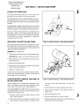
SERIAL NUMBER AND SERIES CODE
LOCATION
2. When servicing the power panel, motor, and pump
or any portion of the system where high voltages
may be encountered, ensure power to the Whirlpool Bath is OFF.
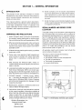
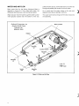
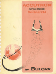
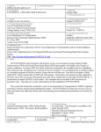
The serial number is an 8-character code assigned to
each Whirlpool Bath to provide a uniform method of
permanently identifying each unit. The series code is a
two (2) character alpha code identifying a specific
feature of the Whirlpool model and is located on the
same label as the serial number. Both codes are
located on a label attached to the Whirlpool Bath pipe
harness retu rn line directly above the ai r switch power
panel. It is visible after installation with the access
panel removed (refer to Figure 1-1).
3. All electrical work shall be performed by a qualified
electrician or ASR.
All warranty reports and invoices must include the
serial number and series code.
4. Pump motor may operate at high temperatures;
avoid coming in contact with motor shell while
pump motor is operating or shortly after shutdown.
The
•
•
•
•
•
WARNINGS AND PRECAUTIONS
1. Kohler Company does not assume responsibility
for warranty repairs performed by anyone other
than an Authorized Service Representative (ASR).
(
10. Kohler Company will not assume responsibility
for product performance or safety where replacement components or parts other than Genuine
Kohler Replacement Parts or authorized alternates
are used.
5. After servicing the Whirlpool Bath, always reinstall all safety devices as originally found priorto
repair or service.
6. Local electrical codes may require use of a Ground
Fault Circuit Interrupter (GFCI) on circuits supplying power to the Whirlpool Bath. Kohler Company requires the use of a GFCI on all installations.
7. All finish materials - enamels, acrylic, plating,
etc. - can easily be damaged. Do NOT stand or
place tools in Whirlpool Bath. Kohler Company
will not be held responsible for damage to finish
caused during repair.
serial number indicates the following:
Manufacturing facility.
The decade in which it was manufactured.
The year of manufacture.
The month of manufacture.
In-plant identification.
Serial Number
and Series Code
Label Location
/:fP
8. Modifications, additions, or deletions shall not be
made to Kohler Whirlpool Baths.
t
9. Instructions, drawings, and schematics contained
in this manual represent information available at
time of printing. Although every attempt has been
made to keep them as up-to-date as possible,
Kohler Company reserves the right to implement
product changes without prior notice.
Guillen's Enterprises, inc
Original Kohler Parts
guillens.com
800-222-7855
Figure 1-1. Serial Number and Series Code Location
Examples:
The series code indicates the following:
• SA - Whirlpool Timing System with air actuator/
aspirator and air switch controls.
• Refer to Plate Number - SA in the SP3A Service
Parts Catalog.
This service manual applies to Whirlpool Baths with
the series code "SA" only.
ForWhirlpool Baths with series codes other than SA or
no series code, refer to the following:
• Kohler Whirlpool Service Manual With Electronic
Timer. Publication Number 105582.
• Kohler Whirlpool Service Manual With Air Actuated Controls. Publication Number 105583.
Manufacturing Facility Code - The first character
(alpha) in the string of numbers as listed below.
Manufacturing
Facility
Code Pre
Jan. 1, 1983
Code Post
Jan. 1, 1983
Brownwood
Richmond
Spartanburg
Toledo
Wisconsin
C
R
B
A
D
T
R
S
A
W
Decade When Manufactured - The second character
(numeric) in the string of numbers.
Examples: 7 for the 70's, 8 for the 80's, etc.
Year of Manufacture - The third character (numeric)
in the string of numbers.
Examples: 8 for 78, 1 for 81, 2 for 82, etc.
Month of Manufacture - The fourth character (alpha)
in the string of numbers as listed below.
Month
January
February
March
April
May
June
Code
A
B
C
D
E
F
Month
July
August
September
October
November
December
Code
G
H
J
K
L
In-Plant Identification - The fifth through eighth
characters (numeric) in the string of numbers are used
for in-plant identification.
2
• Manufactured pre January 1, 1983. D78A0006
- D. Wisconsin manufacturing facility.
- 7. Manufactured in the 70's.
- 8. Manufactured in 1978.
- A. Manufactured in January.
• Manufactured post January 1, 1983. W83B0006
-
W.
8.
3.
B.
Wisconsin manufacturing facility.
Manufactured in the 80's.
Manufactured in 1983.
Manufactured in February.
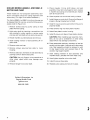
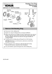
SERVICE AND MAINTENANCE
Kohler Whirlpool Baths require a minimum of maintenance for trouble-free operation. Removal and replacement procedures, as well as repair techniques for
the various components of the Whirlpool Bath, are
provided in the following sections of this manual.
Only commonly used tools are required to service
Kohler Whirlpool Baths, however, a multi meter is
required to test the electrical components of the
system.
Service should be performed by an Authorized Service
Representative (ASR).
WARNING: When servicing the power panel assembly,
motor, and pump or any other portion of the system
where high voltages may be present, ensure the power
to the Whirlpool Bath is OFF. If voltage measurements
are required, use caution.
Service and maintenance procedures described in
this manual apply to all models of the Whirlpool Bath
furnished with air switch controls (series "SA"). Although component configuration may differ from
model to model, operation and service are relatively
the same.
Guillen's Enterprises, inc
Original Kohler Parts
guillens.com
800-222-7855
))
SECTION 2- GENERAL SYSTEM DESCRIPTION
(
THEORY OF OPERATION
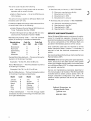
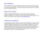
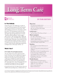
Each air actuated Kohler Whirlpool Bath typically
consists of four basic components:
• Tub which acts as a reservoir for the water and
provides a location for whirlpool action.
• Air control actuator/aspirator which turns the
Whirlpool Bath ON and OFF through activation
of the air switch, relay, and timer assembly (refer
to Figure 2-1).
• Power panel assembly which includes air switch,
relay, and timer assembly to drive the motor and
pump.
• Motor and pump which provide the power to
move the water and create the whirlpool action.
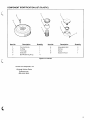
COMPONENT IDENTIFICATION LIST
(
3
I
5
Item No.
1
2
3
,
Description
Motor and Pump
Aspirator/Actuator
Power Panel Assembly
Item No.
Description
4
5
6
Adjustable Jets
Water Suction Inlet
Adjustable Air Aspirator Valve
Figure 2-1. Whirlpool Components
Guillen's Enterprises, inc
Original Kohler Parts
guillens.com
800-222-7855
3
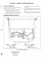
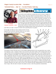
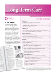
WATER AND AIR FLOW
Basic water flow for the Kohler Whirlpool Bath is
depicted in Figure 2-2. Once filled with water, the
Whirlpool Bath becomes a self-contained system.
Water is drawn from the tub through the water suction
inlet typically located near the bottom of the tub,
pulled into the pump, and forced back out to the tub
through adjustable jets located in the tub walls.
Air is mixed with the water stream at the jets and
adjusted using the air aspirator controls.
J)
This cycle continues as long as the motor and pump
are operating.
Guillen's Enterprises, inc
Original Kohler Parts
guillens.com
800-222-7855
Motor and Pump
Actuator/Aspirator "111/'
)
Adjustable
Jet
...... Water
Figure 2-2. Water and Air Flow
)
4
(
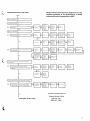
TROUBLESHOOTING FLOW CHART
NOTE: This flow chart has been designed as a 7 step
checklist procedure to be performed by a Kohler
Authorized Service Representative (ASR)
START
I
I
l
Fill Whirlpool Bath above Jets
~
Turn supply GFCI breaker on
0
I
I
a.
~
GFCI stays on.
~ YES
I
a
I
~
YES
GFCI Installed
properly?
f-
Motor
running?
I-
Electrical
connections
tight and
Installed
correctly?
r-
Power on?
r-
Suction
clear?
-
Ail Jets open?
l-
YES
Water leaks.
mOisture
damaged
wiring?
YES
Air tubing
NO
I-
GFCI
defective
J
Press air actuator/aspirator
0
I
~
NO
Whirlpool action starts
I-
NO
loose, kinked
or filled with
water?
t-
Relay starts
motor when
sWitched
manually?
Electrical
connections
tight and
Installed
correctly?
-
Pump Impeller
loose on
motor shaft?
r-
Electrical
connections
tight and
Installed
correctly?
f---
Suction
clear?
r-
PIping
blocked?
t-
NO
YES
t-
Replace air
sWitch
assembly
lYES
0
I
b
Whirlpool water flow through all jets sufficient for
good whirlpool action
YES
(
,
1 Turn air actuator/aspirator fully counterclockwise, then
fully clockWise
0
a
'I
,
Air Injection maximum when air actuator/
aspirator fully counterclockwise, stops when fully
clockWise
Jets open?
-
Onflces
Installed In
Jets?
f-
Motor voltage
OK? (refer to
motor face
plate)
I-
Anyalr
Injected?
I-
YES
YES
p
b
YES
NO
YES
YES
Reduce or
Increase
supply.
Voltage OK?
NO
I-
YES
YES
YES
YES
Replace
Impeller
Blockage In
pump casing?
NO
f-
Blockage In
PIPing?
n
Replace pump
and motor
J
p
NO
Actuator/
Aspirator
blocked?
NO
t-
YES
Orifices
Installed In
Jets?
t-
Stops. won't
restart?
r-
NO
Replace
Actuator/
Aspirator.
'YES
YES
I
Press air actuator/aspirator, wait 30 seconds, press again
0
+
a.1 Whrrlpool action stops when button is pressed,
then starts again when button IS pressed again.
Air Injection
shuts off?
NO
I-
Replace
Actuator/
Aspirator.
I
~
Air tubing
loose, kinked
or broken?
YES
CONTINUED ON NEXT PAGE
NO
f--
Electrical
connections
tight and
Installed
correctly?
YES
r-
YES
Refer to 3A
Guillen's Enterprises, inc
Original Kohler Parts
guillens.com
800-222-7855
5
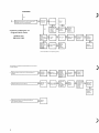
CONTINUED
)
o
b
I
Whirlpool continues to run for 20 minutes when
restarted, then shuts off automatically
P
Stops before
20 minutes
(+
2 min)?
NO
f--
Refer to
Step 8
Doesn't stoP?
1 NO
, YES
YES
Guillen's Enterprises, inc
Original Kohler Parts
guillens.com
800-222-7855
Motor
temperature
normal (below
160 0 F)?
NO
I-
Electrical
connections
tight and
installed
correctly?
r-
Suction
clear?
f--
YES
Shuts off with YES
Actuator!
Aspirator?
rYES
YES
Jets open?
f-
Replace
relay/PC
board
assembly
Motor vents
blocked?
NO
r-
Pump impeller
jammed or
blocked?
NO
I"-
J
jammed or
blocked?
!NO
YES
Electrical
connections
tight and
Installed
correctly?
PIping
YES
r-
GFCI breaker
reset?
~
Replace
relay/PC
board
assembly.
Replace
pump/motor.
The Whirlpool Bath is now operating properly
The following are troubleshooting steps dealing with inconSistent
or erratic operation:
6
l
Whirlpool starts or stops when air actuator/aspirator
rotated
I
Whirlpool starts with no user activity
IS
)
~
F=!
Actuator/
Aspirator IS
blocked?
Separate
120 VAC
Circuit?
110~
in
~ MOisture
plastic tubing?
~
Power outage/
voltage spike?
- NO
~
Remove
Actuator/
Aspirator
Inspect for
damage. and
replace
Power panel
wired
correctly?
(See diagram
on page 7.)
~
Functions
properly?
Water in
actuator
tubing?
~
~
Replace Air
SWitch
Assembly
Tubing kinked
or otherwise
crimped. or
wrapped
around
piping?
~
Relay resets
after each
command?
i
NO
Replace Air
Switch
Assembly
8
I
con~inues
Whirlpool
to run after approximately 20
m in.iactuator Inoperative
rIYE~
Refer to
Step 7
~------------------------~
)
6
Guillen's Enterprises, inc
Original Kohler Parts
guillens.com
800-222-7855
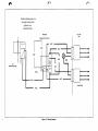
PC Board
117 VAC
Line
I-~
WHT
r0-
GRY
1---1
A ir
Switch A ssembly
/~
BlK
F
..L.....J:
G RY
=
===
b~= =
Relay
'IT
rlJ\
1
1
BlK
...
t-
....
-
--- -
jGRN
BlK
WHT
BlK
..
- -
I
-
..
- Pump Motor
BlK
Figure 2-3. Wiring Diagram
SECTION 3- AIR ACTUATOR/ASPIRATOR ASSEMBLY
THEORY OF OPERATION
When the air control actuator is pressed an air bellows
located in the housing is compressed. At this point the
air bellows delivers a pulse of air to the power panel
and the power panel starts the pump and motor.
SERVICING THE ACTUATOR/ASPIRATOR
ASSEMBLY
Servicing the air actuator/aspirator assembly is limited
to replacement of defective components (refer to
Figure 3-1).
WARNING: Turn GFCI OFF before servicing.
The air control actuator assembly may be serviced
using the following procedure:
1. Gently pry dual control aircap from air control
actuator assembly.
2. Gently pry tapered trim cap from housing.
CAUTION: Tapered trim cap may be sealed with
RTV sealant. Use care when removing tapered trim
cap as not to damage finish.
3. While gently pulling outward on air control actuator
assembly, depress both retainer tabs on sides of
control and remove assembly from housing.
4. Remove air bellows from housing. Remove plastic
tubing from air bellows.
CAUTION: Do not allow plastic tube to fall inside
tub enclosure. You may not have access to recover
the tube.
from body unless it is seriously damaged. The
housing cannot be repaired unless a special tool is
obtained. The tool is available from Kohler Consumer Affairs.
))!
5. Remove housing from body using a special tool and
turning counterclockwise.
6. Remove gasket.
7. Replace parts as necessary.
To reassemble:
1. Install housing into body from inside of bath and
tighten clockwise. NOTE: Use teflon tape on housing threads. The use of RTV silicone sealant should
be avoided.
2. Attach plastic tubing to bellows. Install air bellows
and gasket in housing.
3. Install air control actuator assembly in housing. The
stationary lugs toward the bottom of the air control
actuator assembly must align with the matched
grooves molded into the housi ng. The retai ner tabs
must align with the slots at the top of the housing.
Press and snap into place.
4. Apply small amount of RTV sealant under tapered
trim cap. Press tapered trim cap onto housing.
)
5. Align drive lugs on air control actuator assembly
with matching holes in underside of dual control
aircap. Press dual control aircap onto air control
actuator assembly.
6. Fill Whirlpool Bath. Turn GFCI ON and test for
proper operation.
NOTE: The dual control aircap, tapered trim cap, air
control actuator, air bellows, and gasket may be
replaced at this point. Do NOT remove housing
Guillen's Enterprises, inc
Original Kohler Parts
guillens.com
800-222-7855
)
8
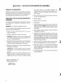
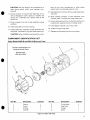
COMPONENT IDENTIFICATION LIST
{
Guillen's Enterprises, inc
Original Kohler Parts
guillens.com
800-222-7855
Item No.
1*
2*
3*
Description
Quantity
Dual Control Aircap
Spring Ring (Part of Item 1)
Tapered Trim Cap
4
Air Control Actuator
Assembly
*Part of Trim Kit
Item No.
5
6
7
8
9
Description
Quantity
Air Bellows
Gasket
Housing
Gasket
Body
Figure 3-1. Actuator/Aspirator Assembly
9
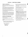
SECTION 4- POWER PANEL ASSEMBLY
THEORY OF OPERATION
The power panel consists of the electrical box, cover,
gasket, air switch assembly, PC board, and relay (refer
to Figure 4-1).
When the whirlpool is off and the air actuator/aspirator
control is pressed, the air pulse momentarily closes
the air switch and relay in the power panel. The air
switch and relay in turn activates the power supply to
the pump motor and timer (PC board) circuitry.
After approximately 20 minutes of operation, the timer
circuitry deactivates power to the pump motor, stopping the whirlpool action.
If the air actuator/aspirator control is pressed while the
whirlpool pump is on, the air pulse again momentarily
closes the air switch and relay in the power panel,
interrupting power to the pump motor and stopping
the whirlpool action. The timer (PC board) then
automatically resets at approximately 20 minutes.
SERVICING THE POWER PANEL
Servicing the power panel is limited to replacement of
defective components.
2. Mark and disconnect leads to air switch assembly.
Remove air switch from electrical box by depressing retainer tabs. Disconnect plastic tubing
from air switch.
1
3. Loosen screws securing relay mounting bracket
to electrical box. Remove relay and PC board
bracket from electrical box.
4. Mark and disconnect leads from relay.
5. Replace components as necessary.
6. Connect leads to replacement relay.
CAUTION: Leads must be installed on terminals
as outlined on Wiring Diagram (Figure 2-3). Failure
to install leads on correct terminals will result in
erratic operation of the Whirlpool Bath.
7. Install replacement relay and PC board mounting
bracket in electrical box. Tighten screws securely.
8. Connect leads to air switch and install air switch in
electrical box. Connect plastic tubing to air switch.
9. Install gasket on electrical box cover. Install cover
and gasket on electrical box.
To service the power panel, proceed as follows:
10. Install screws securing cover and gasket to electrical box. Tighten screws securely.
CAUTION: Turn GFCI OFF before servicing the power
panel.
11. Turn GFCI ON and fill Whirlpool Bath. Test
operation of power panel.
1. Remove screws securing electrical box cover to
electrical box. Remove electrical box cover.
Remove and replace gasket if damaged.
Guillen's Enterprises, inc
Original Kohler Parts
guillens.com
800-222-7855
}
10
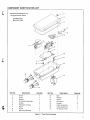
COMPONENT IDENTIFICATION LIST
Ie
Guillen's Enterprises, inc
Original Kohler Parts
guillens.com
800-222-7855
2
I
I
I
I
I
I
I
v/
/'
/
/'
14
Item No.
2
3
4
5
6
7
8
9
Description
Quantity
Item No.
Screw
Cover
Gasket
Air Switch Assembly
Holder
PC Board (Timer)
Relay
Screw
Mounting Bracket
4
10
11
1
2
4
12
13
14
15
16
17
Description
Bolt
Washer
Screw
Enclosure
Hanger
Cable Assembly
Cable Assembly
Air Switch Tube
Quantity
2
2
1
2
Figure 4-1. Power Panel Assembly
11
Guillen's Enterprises, inc
Original Kohler Parts
guillens.com
800-222-7855
SECTION 5- MOTOR AND PUMP
1
THEORY OF OPERATION
The motor and pump work as a unit; the motor
provides the drive power for the pump impeller.
Air
The whirling action of the impeller creates a vacuum,
pulling water into the inlet port. The incoming water is
forced through the impeller and out through the water
harness.
Adjustable jets, located on the sides of the tub, provide
outlets for the circulating water and serve to divert the
flow of the water for more effective whirlpool action.
Figures 5-1 and 5-2 illustrate how air is aspirated into
the water stream as the water passes through the
adjustable jets. The amount of air mixed with the water
is controlled by the two adjustable air aspirators
located on top of the tub.
SERVICING THE MOTOR AND PUMP
Figure 5-1. Water/Air Mixture - Brass Whirlpool System
The motor and pump should be removed from the
Whirlpool Bath for all service and maintenance activities. Removal and replacement can be accomplished
using the following procedure:
WARNING: Turn GFCI OFF.
1
1. Disconnect pump from suction and harness tubes.
CAUTION: Be careful not to strip threads on studs.
2. Remove bolts or nuts and washers securing motor
and pump to tub.
3. Remove motor and pump.
4. Disconnect motor power cord leads from air switch
power module at the motor.
5. Replace in reverse order.
Once the motor and pump has been removed, determine which model had been installed. Follow service
procedures for that model only.
KOHLER MODELS 60660-M, AND 60661-M
MOTOR AND PUMP
These models are 1/2 horsepower assemblies, identical in all aspects except for casing alignment with
motor body. (For right or left outlet installation.)
The Kohler 60660-M or 60661-M motor and pump can
be disassembled for service using the following procedure (refer to Figure 5-3):
1. Remove screws securing pump casing to seal
plate. Remove casing.
2. Hold motor shaft by inserting a screwdriver into
slot provided in motor casing; or remove motor
12
Figure 5-2. Water/Air Mixture - Plastic Whirlpool System
end cover and hold shaft with an open end
wrench.
3. Rotate impeller counterclockwise and remove.
4. Slide rotating member of seal assembly off impeller shaft.
5. Remove seal plate a-ring.
6. Remove seal plate from motor housing.
7. Remove stationary members of seal assembly by
pushing out from behind plate.
)
•
CAUTION: Use only fingers, not a screwdriver or
other sharp object which may damage components .
8. Check impeller, O-ring and seal assembly. If any
item is damaged or worn, replace it. Impeller and
casing are a matched pair; replace both at the
same time.
9. Clean impeller hub and all seal assembly cavity
surfaces.
bers, do not use a screwdriver or other sharp
object which may damage ceramic ring.
12. Seat stationary members firmly using finger pressure only.
13. Slide rotating member of seal assembly onto
impeller shaft. Lubricate with clean water only.
14. Ensure grooved portions of rotating member are
located over raised portions of impeller shaft.
15. Hand tighten impeller onto motor shaft.
10. Install seal plate on motor housing.
11. Install stationary members of seal assembly into
face plate. Lubricate O-ring with clean water only.
16. Install O-ring on seal plate.
17. Replace pump casing and secure in place.
CAUTION: When installing seal assembly mem-
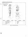
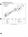
COMPONENT IDENTIFICATION LIST
Kohler Models 60660-M and 60661-M Motor and Pump
8
Guillen's Enterprises, inc
Original Kohler Parts
guillens.com
800-222-7855
\
•
Item No.
•
2
3
4
Description
Casing
Screw
O-Ring
Impeller
Quantity
Item No.
Description
1
5
6
7
8
Pump Seals
Seal Plate
Slinger
Motor
6
Quantity
Figure 5-3. Motor and Pump
13
KOHLER MODELS 60660-H, AND 60661-H
MOTOR AND PUMP
These models are 1/2 horsepower assemblies, identical in all aspects except for casing alignment with
motor body. (For right or left outlet installation.)
The Kohler 60660-H or 60661-H motor and pump can
be disassembled for service using the following procedure (refer to Figure 5-4):
1. Remove screws securing pump casing to face
plate. Remove casing.
2. Hold motor shaft by inserting a screwdriver into
slot provided in motor casing; or remove motor
end cap and hold shaft with an open end wrench.
3. Rotate impeller counterclockwise and remove.
4. Slide rotating member of seal assembly off impeller shaft.
5. Remove motor end cap.
6. Remove screws securing face plate to motor
housing.
7. Remove stationary members of seal assembly by
pushing out from behind face plate.
CAUTION: Use only fingers, not a screwdriver or
other sharp object which may damage components.
8. Remove slinger from motor shaft.
9. Check impeller, O-ring, shaft sleeve, and seal
assembly. If any item is damaged or worn, replace
it. Impeller and casing are a matched pair; replace
both at the same time.
))
10. Clean impeller hub and all seal cavity surfaces.
11. Install slinger on motor shaft. Ensure that flange of
slinger is facing threaded end of shaft.
12. Install O-ring on ceramic seal member. Ensure it is
properly seated.
13. Press ceramic ring into clear plastic retainer.
14. Attach face plate to motor housing.
15. Install O-ring on cut ridge of clear plastic retainer.
CAUTION: When installing seal assembly members, do not use a screwdriver or other sharp
object which may damage components.
16. Press assembled stationary members of seal assembly into face plate. Lubricate with clean water
only. Seal assembly should be pressed in with
O-ring toward motor and exposed face of the
ceramic ring toward impeller.
17. Slide rotating member of seal assembly onto
impeller shaft. Lubricate with clean water only.
18. Hand tighten impeller onto motor shaft.
19. Install O-ring on face plate.
)/
20. Replace pump casing and secure in place.
Guillen's Enterprises, inc
Original Kohler Parts
guillens.com
800-222-7855
)
14
COMPONENT IDENTIFICATION LIST
•
Kohler Models 60660-H and 60661-H Motor and Pump
Guillen's Enterprises, inc
Original Kohler Parts
guillens.com
800-222-7855
"
,.
I
I,@
~\
®\
9
12
13
•
Item No.
1
2
3
4
5
6
7
Description
Screw
Casing
O-Ring
Impeller
Pump Seals
Face Plate
Slinger
Quantity
6
Item No.
8
9
10
11
12
13
Description
Motor
Screw
End Cap
Insulating Bushing
Insulating Bushing
Nut
Quantity
1
4
1
2
2
6
Figure 5-4. Motor and Pump
•
15
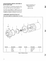
KOHLER MODELS 60662-M, AND 60663-M
MOTOR AND PUMP
Guillen's Enterprises, inc
Original Kohler Parts
guillens.com
800-222-7855
These models are 3/4 horsepower assemblies, identical in all aspects except for casing alignment with
motor body. (For right or left outlet installation.)
)
The Kohler Model 60662-M or 60663-M motor and
pump can be disassembled for service using the same
procedures outlined for disassembly and service as
the60660-M and 60661-M. See page 13 of this manual.
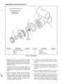
COMPONENT IDENTIFICATION LIST
Kohler Models 60662-M and 60663-M Motor and Pump
8
7
2
1---;
4
I
5
Item No.
1
2
3
4
Description
Casing
Screw
O-Ring
Impeller
Quantity
Item No.
Description
1
6
5
6
7
8
Pump Seals
Seal Plate
Slinger
Motor
Quantity
Figure 5-5. Motor and Pump
))
16
•
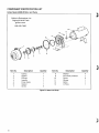
KOHLER MODEL 60388-M MOTOR AND
PUMP
This model is a 1 horsepower assembly.
The Kohler Model 60388-M motor and pump can be
disassembled for service using the following procedure (refer to Figure 5-6):
1. Remove screws securing casing to motor. Remove
casing.
2. Lift off diffuser and gasket.
3. Hold motor shaft by inserting screwdriver into slot
provided in motor casing; or remove motor end
cover and hold shaft with an open end wrench.
10. Clean impeller and all seal assembly cavity surfaces thoroughly before reassembling.
11. Secure face plate to motor housing.
12. Install stationary members of seal assembly into
the face plate. Lubricate gasket with clean water
only.
CAUTION: When installing seal assembly members, do not use a screwdriver or other sharp
object which may damage ceramic ring.
4. Rotate impeller counterclockwise and remove.
13. Seat stationary members firmly, using finger pressure only.
5. Slide rotating member of seal assembly off impeller
shaft.
14. Slide rotating member of seal assembly onto
impeller shaft. Lubricate with clean water only.
6. Remove diffuser O-ring and face plate gasket.
15. Ensure grooved portions of rotating member are
located over raised portions of impeller shaft.
7. Remove screws and lockwashers securing face
plate and bracket to motor housing. Remove face
plate and bracket.
•
and all pump seals. If any item is damaged or
worn, replace it. Impeller, casing, and diffuser are
a matched set; replace at the same time .
16. Hand tighten impeller onto motor shaft.
8. Remove stationary members of seal assembly by
pushing out from behind face plate and bracket.
17. Place diffuser over impeller with word "TOP" at
top. Stop lug will be in 6 o'clock position. Ensure
the O'ring is securely in place.
CAUTION: Use only fingers, not a screwdriver or
other sharp object which may damage components.
18 . Lubricate with water. Then place gasket in groove
on face plate and bracket. Ensure gasket is sealed
properly.
9. Check impeller, diffuser, diffuser O-ring, gasket,
19. Replace pump casing and secure in place.
Guillen's Enterprises, inc
Original Kohler Parts
guillens.com
800-222-7855
'.
17
COMPONENT IDENTIFICATION LIST
Kohler Model 60388-M Motor and Pump
)
Guillen's Enterprises, inc
Original Kohler Parts
guillens.com
800-222-7855
})
Item No.
2
3
4
5
6
7
Description
Casing
Gasket
Diffuser
Impeller
Pump Seals
Gasket
Screw
Quantity
Item No.
Description
Quantity
8
9
Washer
Face Plate, Bracket
Screw
Slinger
Motor
O-Ring
4
10
11
12
13
8
4
Figure 5-6. Motor and Pump
))
18
•
Guillen's Enterprises, inc
Original Kohler Parts
guillens.com
800-222-7855
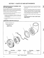
SECTION 6- TRIM KITS
SERVICING THE TRIM KITS
Trim kit components are designed for long life. However, if one needs to be replaced, use the following
procedures:
Adjustable Jets (Brass)
The adjustable jets are serviced using the following
procedure (refer to Figure 6-1):
1. Remove two screws securing retainer to jet
housing.
2. Pull on center of ball and remove assembly from
housing. Assembly may be tightly sealed. If necessary, use small Phillips screwdriver in screw
hole to remove assembly.
•
4. Fit hair screen into groove on back of hood.
5. Attach screen and hood squarely to inlet housing.
Ensure riveted portion of screen is located toward
bottom of tUb.
6. Secure hood and screen into place.
Adjustable Jets (Plastic)
The adjustable jets are serviced using the following
procedure (refer to Figure 6-2):
1. Using a small screwdriver loosen the ball lock ring.
2. Remove ball and lock ring from jet housing.
3. Disassemble assembly into ball, O-ring, retainer,
and plastic insert bearing.
3. Using a 9/16 inch socket wrench remove the orifice
from the jet housing.
4. Remove trim ring only if it is damaged. It may be
sealed with RTV sealant.
4. Replace parts as required and clean all surfaces
before reassembly.
5. Replace parts as required and clean all surfaces
before reassembly.
5. Assemble orifice into jet housing.
6. If trim ring is removed and replaced, remove dirt,
grease, moisture, and RTV from jet housing flange .
7. Apply RTV sealant to underside lip of trim ring.
8. Carefully snap trim ring into flange on tub. Ensure
that dimples in trim ring align with notches in jet
housing.
9. Apply light film of lubricant to two O-rings and
plastic insert bearing.
10. Install O-rings on retainer. One is installed inside,
the other in groove on outside of retainer.
11. Assemble ball and plastic insert bearing into
retainer.
12. Insert ball and retainer into jet housing, being
careful not to drop plastic bearing into housing.
13. Align screw holes and secure retainer to jet
housing.
14. Tighten screws until ball moves freely with slight
side to side pressure.
Suction Inlet (Brass)
•
3. Replace any parts as necessary and clean all
surfaces before reassembly.
6. Assemble ball and ball lock ring into jet housing.
Tighten with small screwdriver.
NOTE: See Section 7 for expanded service of
Plastic Jets and Suction.
Suction Inlet (Plastic)
The water suction inlet is serviced using the following
procedure (refer to Figure 6-2):
1. Remove screw securing suction hood to inlet
housing.
2. Remove hood from inlet housing by unscrewing
hood counterclockwise.
3. Replace any parts as necessary and clean all
surfaces before reassembly.
4. Secure hood into place.
5. Install screw securing suction head to inlet housing.
WARNING: The whirlpool must not be operated
without the suction hood installed.
NOTE: See Section 7 for expanded service of
Plastic Jets and Suction.
The water suction inlet is serviced using the following
procedure (refer to Figure 6-1):
SERVICING THE ASPIRATOR ASSEMBLY
1. Remove screw securing suction hood and screen to
inlet housing.
Refer to SECTION 3 - SERVICING THE ACTUATOR/ASPIRATOR ASSEMBLY. Omit references to
the air bellows. All other service procedures are the
same.
2. Remove hood and hair screen.
19
COMPONENT IDENTIFICATION LIST (BRASS)
Guillen's Enterprises, inc
Original Kohler Parts
guillens.com
800-222-7855
1
/
Item No.
2
3
4
5
6
4
/
Description
Item No.
Dual Control Aircap
(Includes Item 2)
Spring Ring
Tapered Trim Cap
Aircap (Includes
Item 2)
O-Ring
Screw
7
8
9
10
11
12
13
14
Figure 6-1. Trim Kits
20
Description
Retainer
O-Ring
Directional Ball
Insert Bearing
Trim Ring
Screw
Suction Hood
Screen
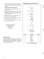
COMPONENT IDENTIFICATION LIST (PLASTIC)
1
30
\~
~/
~
Item No.
2
3
4
5
Description
Control Knob
O-Ring
Trim Cap
Setscrew
Ball Retaining Ring
Quantity
Item No.
6
7
8
9
Description
Adjustable Ball
Orifice
Screw
Suction Hood
4
Quantity
4
4
1
4
Figure 6-2. Trim Kits
(
Guillen's Enterprises, inc
Original Kohler Parts
guillens.com
800-222-7855
{
21
SECTION 7- PLASTIC JET AND SUCTION SERVICE
SERVICING PLASTIC JET ASSEMBLY AND
SUCTION ASSEMBLY
Kits are available through your Kohler Service Parts
Supplier which include the components illustrated in
Figures 7-1 and 7-2. Also included are adjacent fittings
and short pieces of flexible PVC tubing.
To service the jet and suction assemblies using the
repair kits, follow these procedures:
1. Analyze the damaged jet, adjacent fittings, and
tube diameters. Choose the parts in the kit needed
for the repair job.
3. Remove all attachments to the wall fitting (flange)
including ball and retainer assembly or suction
hood cover.
4. Remove the wall fitting (flange) with a jet spanner
wrench and ratchet/socket by turning counterclockwise. Make sure there is complete engagement of the wrench pins in the wall flange sockets
to prevent damage to flange or bath walls.
5. Cut all water and air supply tubes to damaged jet
housing.
CAUTION: DO NOT CUT ANY CLOSER THAN 3"
FROM THE JET.
2. Provide suitable protection for acrylic surfaces of
the bath.
COMPONENT IDENTIFICATION LIST
50
Guillen's Enterprises, inc
Original Kohler Parts
guillens.com
800-222-7855
\
)
Bath Shell
2
Item No.
Description
1
2
Screw
Suction Hood (Includes
Item 1)
Quantity
Item No.
3
4
5
Figure 7-1. Suction Assembly
22
Description
Wall Flange
Gasket
Suction Housing
Quantity
1
1
1
COMPONENT IDENTIFICATION LIST
Guillen's Enterprises, inc
Original Kohler Parts
guillens.com
800-222-7855
Item No.
Description
1
Wall Flange (Includes
Item 5)
Gasket
2
Quantity
Item No.
3
4
5
Description
Quantity
Orifice
Housing
Ball and Retainer
Figure 7-2. Jet Assembly
6. Salvage and clean all removed parts including
beveled gasket, wall flange, jet orifice, and orifice
insert for possible reuse. Inspect thoroughly for
damage before reusing. Clean all old RTV silicone
sealant from hole.
7. Using the PVC primer and cement (follow the
manufacturer's instructions), install suitable tube
couplings to the cut ends of the air or water supply
tubes.
{
8. Clean and cement suitable reducing bushings,
plugs, or adapters to the new jet or suction
housing. Place the new housing over the hole and
determine the proper length of flexible tubing
required to bridge the distance between the jet
and water and air supply tubes.
9. Cut lengths of flexible tubing allowing enough
length for complete seating in the jet and coupling
sockets.
10. Slip fit the flexible tubes and temporarily install the
housing to the wall flange (without gluing or
sealing) to ensure that your measurements are
correct.
11. Keep the housing aligned with the hole and
cement the tubes to the housing and couplings.
12. Reinstall the wall flange to the housing with the
gasket behind the bath wall (beveled edge to the
wall). Draw a bead of silicone around the flange
being sure to avoid the threads. Thread the flange
into the housing. Before tightening completely,
23
apply a bead of silicone sealant between the rear
bath wall and the beveled side of the gasket.
Complete tightening until the gasket begins to
compress.
COMPONENT IDENTIFICATION LIST
CAUTION: DO NOT OVERTIGHTEN.
If the gasket pops out, loosen the wall flange and
repeat the process.
13. Wipe away excess silicone from the inside of the
bath wall and apply silicone around the housing at
the rear of the unit. Clean the inside of the unit
before silicone cures.
14. Make sure that you have installed the correct
orifice insert into the new housing.
15. Replace the wall fitting attachments. For example:
ball and retainer, or suction cover.
5
16. Allow 3 hours for a complete cure of silicone and
PVC cement before testing.
Guillen's Enterprises, inc
Original Kohler Parts
guillens.com
800-222-7855
)
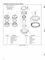
SERVICE NOTE
K-1512 "SA" Hourglass Whirlpools and K-1492 "SA"
Greek Whirlpools are still equipped with air actuator
assemblies shown in Figure 7-3. Refer to: KOHLER
WHIRLPOOL SERVICE MANUAL No. 105583 for
actuator service instructions.
Item No.
Description
1
2
3
Knob
Trim Cap
Collar
C-Clip
Actuator
Housing
Fastener
4
5
6
7
Figure 7-3. Actuator Assembly
24
Quantity
Guillen's Enterprises, inc
Original Kohler Parts
guillens.com
800-222-7855
Limited One- Year Warranty
Kohler plumbing fixtures and fitt ings are warranted free of manu facturi ng defects.
Kohler Co. will at its election repair. rep lace or make appropriate adjustment where Koh ler Co. inspection discloses
any such defects occurring in normal usage within one year after installation . Kohler Co. is not responsible for
installation costs.
To obtain warranty service. contact Kohler Co. either through your Dealer or Plumbing Contractor or by writing
Kohler Co .. Attn: Consumer Affai rs Department, Koh ler. Wisconsin 53044 U.S.A.
Implied warranties including that of merchantability are expressly limited in duration to the duration of this warranty.
Kohler Co. disclaims any responsibility for consequential damages. Some states do not allow limitations on how
long an implied warranty lasts. or the exclusion or limitation o f inciden tal or consequential damages. so th is
limitation and exclusion may not apply to you. This warranty gives you specific legal rights. You may also have other
rights which vary from state to state.
Th is is ou r exclusive written warran ly.
KOHLER
Pllbl lC<ll ,on Nlirnoo, l00Hl4..Q884
KOHLER CO KOHLER WISCONSIN 530<14